CN116146147B - A bridge plug with two-way sealing structure - Google Patents
A bridge plug with two-way sealing structureDownload PDFInfo
- Publication number
- CN116146147B CN116146147BCN202310402096.3ACN202310402096ACN116146147BCN 116146147 BCN116146147 BCN 116146147BCN 202310402096 ACN202310402096 ACN 202310402096ACN 116146147 BCN116146147 BCN 116146147B
- Authority
- CN
- China
- Prior art keywords
- ring
- slip
- bridge plug
- rubber ring
- gluey
- Prior art date
- Legal status (The legal status is an assumption and is not a legal conclusion. Google has not performed a legal analysis and makes no representation as to the accuracy of the status listed.)
- Active
Links
- 238000007789sealingMethods0.000titledescription21
- 230000006835compressionEffects0.000claimsabstract2
- 238000007906compressionMethods0.000claimsabstract2
- 230000008878couplingEffects0.000claims1
- 238000010168coupling processMethods0.000claims1
- 238000005859coupling reactionMethods0.000claims1
- 230000002457bidirectional effectEffects0.000abstractdescription4
- 230000000903blocking effectEffects0.000description9
- 230000000694effectsEffects0.000description2
- 238000002955isolationMethods0.000description2
- 238000000034methodMethods0.000description2
- 238000012986modificationMethods0.000description2
- 230000004048modificationEffects0.000description2
- 238000010586diagramMethods0.000description1
- 238000005553drillingMethods0.000description1
- 239000007788liquidSubstances0.000description1
- 239000003129oil wellSubstances0.000description1
- 239000003079shale oilSubstances0.000description1
Images
Classifications
- E—FIXED CONSTRUCTIONS
- E21—EARTH OR ROCK DRILLING; MINING
- E21B—EARTH OR ROCK DRILLING; OBTAINING OIL, GAS, WATER, SOLUBLE OR MELTABLE MATERIALS OR A SLURRY OF MINERALS FROM WELLS
- E21B33/00—Sealing or packing boreholes or wells
- E21B33/10—Sealing or packing boreholes or wells in the borehole
- E21B33/13—Methods or devices for cementing, for plugging holes, crevices or the like
- E21B33/134—Bridging plugs
- Y—GENERAL TAGGING OF NEW TECHNOLOGICAL DEVELOPMENTS; GENERAL TAGGING OF CROSS-SECTIONAL TECHNOLOGIES SPANNING OVER SEVERAL SECTIONS OF THE IPC; TECHNICAL SUBJECTS COVERED BY FORMER USPC CROSS-REFERENCE ART COLLECTIONS [XRACs] AND DIGESTS
- Y02—TECHNOLOGIES OR APPLICATIONS FOR MITIGATION OR ADAPTATION AGAINST CLIMATE CHANGE
- Y02A—TECHNOLOGIES FOR ADAPTATION TO CLIMATE CHANGE
- Y02A30/00—Adapting or protecting infrastructure or their operation
- Y02A30/30—Adapting or protecting infrastructure or their operation in transportation, e.g. on roads, waterways or railways
Landscapes
- Life Sciences & Earth Sciences (AREA)
- Engineering & Computer Science (AREA)
- Geology (AREA)
- Mining & Mineral Resources (AREA)
- Physics & Mathematics (AREA)
- Environmental & Geological Engineering (AREA)
- Fluid Mechanics (AREA)
- General Life Sciences & Earth Sciences (AREA)
- Geochemistry & Mineralogy (AREA)
- Pressure Vessels And Lids Thereof (AREA)
Abstract
Description
Translated fromChinese技术领域technical field
本发明涉及桥塞技术领域,尤其是涉及一种双向封堵结构的桥塞。The invention relates to the technical field of bridge plugs, in particular to a bridge plug with a bidirectional blocking structure.
背景技术Background technique
页岩油气开采过程中,因油气分布在不同的井下区域,油井会穿过多个油气层区域。油气井下的完井过程,需要从最底层油气层开始逐个对油气层区域进行射孔并进行压裂作业。每一级的射孔压裂前,需要对前一级已完成射孔压裂的油气层进行封堵,以保证各层压裂所需的液体流量及压力不被已压裂的油气层分流分压。现有技术提供的桥塞包括:中心管、胶筒和两个卡瓦,胶筒和两个卡瓦套装在中心管上且胶筒位于两个卡瓦之间。使用时卡瓦与套管锚定,并挤压胶筒使胶筒膨胀坐封将桥塞固定在套管内。投入与中心管适配的可溶密封球封堵管口,即可完成封隔。封隔作业完成后,可溶球溶解,不钻除桥塞也可使套管上下连通。但单个胶筒在井下可能会发生磨损破坏,使桥塞与套管的坐封失效。During the exploitation of shale oil and gas, because the oil and gas are distributed in different downhole areas, the oil well will pass through multiple oil and gas layer areas. The completion process of oil and gas wells requires perforating and fracturing the oil and gas layer areas one by one starting from the bottom oil and gas layer. Before each stage of perforation fracturing, it is necessary to plug the oil and gas layers that have been perforated and fractured in the previous stage, so as to ensure that the liquid flow and pressure required for each layer of fracturing will not be diverted by the fractured oil and gas layers Partial pressure. The bridge plug provided in the prior art includes: a central tube, a rubber tube and two slips, the rubber tube and the two slips are set on the central tube and the rubber tube is located between the two slips. When in use, the slips are anchored to the casing, and the rubber tube is squeezed to expand the rubber tube and set the plug to fix the bridge plug in the casing. Putting in a soluble sealing ball compatible with the center pipe to block the pipe opening can complete the isolation. After the isolation operation is completed, the soluble ball dissolves, and the casing can be connected up and down without drilling to remove the bridge plug. However, a single rubber tube may be worn downhole and damaged, making the setting seal between the bridge plug and the casing invalid.
发明内容Contents of the invention
本发明的目的是提供一种双向封堵结构的桥塞,能够实现双向多层封堵,避免坐封不严密导致的坐封失败,并且能够避免部件滑脱。The purpose of the present invention is to provide a bridge plug with a two-way sealing structure, which can realize two-way multi-layer sealing, avoid setting failure caused by poor setting, and avoid component slippage.
为实现上述目的,本发明提供了一种双向封堵结构的桥塞,套设于芯轴外的管轴上,包括自上而下依次设置的上压环、上卡瓦组件、上卡瓦压台、上封堵机构、中间体、下封堵机构、下卡瓦压台、下卡瓦组件和定位推套,所述上压环与所述上卡瓦组件固定连接,所述上卡瓦压台的下方设置有上内衬环,所述上内衬环的外围设置有所述上封堵机构,所述上封堵机构包括依次连接的第一胶环、上连接环和第二胶环,所述下卡瓦组件的上方设置有下内衬环,所述下内衬环的外围设置有所述下封堵机构,所述下封堵机构包括依次连接的第三胶环、下连接环、第四胶环,所述下卡瓦组件与所述定位推套固定连接。In order to achieve the above purpose, the present invention provides a bridge plug with a two-way sealing structure, which is sleeved on the pipe shaft outside the mandrel, and includes an upper pressure ring, an upper slip assembly, and an upper slip assembly arranged sequentially from top to bottom. Pressing table, upper blocking mechanism, intermediate body, lower blocking mechanism, lower slip pressing table, lower slip assembly and positioning push sleeve, the upper pressing ring is fixedly connected with the upper slip assembly, and the upper slip assembly An upper lining ring is provided under the tile pressure table, and the upper sealing mechanism is provided on the periphery of the upper lining ring. The upper sealing mechanism includes a first rubber ring, an upper connecting ring and a second rubber ring connected in sequence. A rubber ring, a lower inner lining ring is arranged above the lower slip assembly, and the lower sealing mechanism is arranged on the periphery of the lower inner lining ring, and the lower sealing mechanism includes a third rubber ring connected in sequence, The lower connecting ring and the fourth rubber ring, the lower slip assembly is fixedly connected with the positioning push sleeve.
优选的,所述上卡瓦压台和所述下卡瓦压台均为圆锥体,所述上卡瓦压台的圆锥面朝上,所述上卡瓦压台的顶端伸入所述上卡瓦组件与所述管轴之间,所述下卡瓦压台的圆锥面朝下,所述下卡瓦压台的底端伸入所述下卡瓦组件与所述管轴之间。Preferably, both the upper slip press and the lower slip press are conical, the conical surface of the upper slip press faces upward, and the top of the upper slip press extends into the upper Between the slip assembly and the pipe shaft, the conical surface of the lower slip pressing table faces downward, and the bottom end of the lower slip pressing table extends into between the lower slip assembly and the pipe shaft.
优选的,所述第一胶环的顶端与所述上卡瓦压台的底面相连接,所述第二胶环的底面与所述中间体的顶面相连接,所述上连接环套设于所述上内衬环外,所述上内衬环的底边位置低于所述中间体的顶边位置。Preferably, the top end of the first rubber ring is connected to the bottom surface of the upper slip table, the bottom surface of the second rubber ring is connected to the top surface of the intermediate body, and the upper connecting ring is sleeved on Outside the upper lining ring, the bottom edge of the upper inner lining ring is lower than the top edge of the intermediate body.
优选的,所述第三胶环的顶端与所述中间体的底面相连接,所述第四胶环的底面与所述下卡瓦压台的顶面相连接,所述下连接环套设于所述下内衬环外,所述下内衬环的顶边位置高于所述中间体的底边位置。Preferably, the top end of the third rubber ring is connected to the bottom surface of the intermediate body, the bottom surface of the fourth rubber ring is connected to the top surface of the lower slip table, and the lower connecting ring is sleeved on Outside the lower lining ring, the top edge of the lower lining ring is higher than the bottom edge of the intermediate body.
因此,本发明采用上述结构的一种双向封堵结构的桥塞,当分别从两端向上压环和定位推套施力时,上封堵机构和下封堵机构内的各个胶环受力凸出,形成双向多层的封堵结构,达到严密坐封、防止坐封失败的效果。上封堵机构和下封堵机构的各部分之间采用粘接固定,在非工作状态时,防止部件脱落。Therefore, the present invention adopts a bridge plug with the above-mentioned two-way sealing structure. When force is applied to the upward pressure ring and the positioning push sleeve from both ends, the rubber rings in the upper sealing mechanism and the lower sealing mechanism are stressed. Protruding, forming a two-way multi-layer sealing structure, achieving the effect of tight setting and preventing setting failure. The parts of the upper blocking mechanism and the lower blocking mechanism are fixed by bonding to prevent the parts from falling off in the non-working state.
下面通过附图和实施例,对本发明的技术方案做进一步的详细描述。The technical solutions of the present invention will be described in further detail below with reference to the accompanying drawings and embodiments.
附图说明Description of drawings
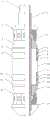
图1为本发明一种双向封堵结构的桥塞实施例的结构示意图;Fig. 1 is the structural schematic diagram of the bridge plug embodiment of a kind of two-way sealing structure of the present invention;
附图标记:Reference signs:
1、芯轴;2、管轴;3、上压环;4、上卡瓦组件;5、上卡瓦压台;6、第一胶环;7、上连接环;8、第二胶环;9、上内衬环;10、中间体;11、下内衬环;12、第三胶环;13、下连接环;14、第四胶环;15、下卡瓦压台;16、下卡瓦组件;17、定位推套。1. Mandrel; 2. Pipe shaft; 3. Upper pressure ring; 4. Upper slip assembly; 5. Upper slip table; 6. First rubber ring; 7. Upper connecting ring; 8. Second rubber ring ;9, upper lining ring; 10, intermediate; 11, lower lining ring; 12, third rubber ring; 13, lower connecting ring; 14, fourth rubber ring; 15, lower slip press table; 16, Lower slip assembly; 17. Positioning push sleeve.
具体实施方式Detailed ways
以下通过附图和实施例对本发明的技术方案作进一步说明。The technical solutions of the present invention will be further described below through the accompanying drawings and embodiments.
实施例Example
如图所示,一种双向封堵结构的桥塞,套设于芯轴1外的管轴2上,包括自上而下依次设置的上压环3、上卡瓦组件4、上卡瓦压台5、上封堵机构、中间体10、下封堵机构、下卡瓦压台15、下卡瓦组件16和定位推套17。上压环3与上卡瓦组件4固定连接,上卡瓦压台5和下卡瓦压台15均为圆锥体,上卡瓦压台5的圆锥面朝上,上卡瓦压台5的顶端伸入上卡瓦组件4与管轴2之间。上卡瓦组件4被压迫时,向下压迫上卡瓦压台5,通过上卡瓦压台5的圆锥面与上卡瓦压台5卡接。下卡瓦压台15的圆锥面朝下,下卡瓦压台15的底端伸入下卡瓦组件16与管轴2之间。下卡瓦组件16与定位推套17固定连接,通过定位推套17压迫下卡瓦压台15,下卡瓦压台15受力上行。As shown in the figure, a bridge plug with a two-way sealing structure is sleeved on the tubular shaft 2 outside the mandrel 1, and includes an
上卡瓦压台5的下方设置有上内衬环9,上内衬环9与上卡瓦压台5一体连接。上内衬环9的外围设置有上封堵机构,上封堵机构包括依次连接的第一胶环6、上连接环7和第二胶环8,第一胶环6的顶端与上卡瓦压台5的底面粘接,第二胶环8的底面与中间体10的顶面粘接。第一胶环6和第二胶环8与上连接环7均粘接。上连接环7套设于上内衬环9外,上内衬环9的底边位置低于中间体10的顶边位置。当上卡瓦压台5受力下行时,上内衬环9的下边缘沿着中间体10向下滑行,第一胶环6受到来自上卡瓦压台5和上连接环7的压迫而凸出,第二胶环8受到上连接环7和中间体10的压迫而凸出,形成位于上方的双层坐封结构。An
下卡瓦组件16的上方设置有下内衬环11,下内衬环11与下卡瓦压台15一体连接。下内衬环11的外围设置有下封堵机构,下封堵机构包括依次连接的第三胶环12、下连接环13、第四胶环14,第三胶环12的顶端与中间体10的底面粘接,第四胶环14的底面与下卡瓦压台15的顶面粘接,第三胶环12和第四胶环14均与下连接环13粘接。下连接环13套设于下内衬环11外,下内衬环11的顶边位置高于中间体10的底边位置。当下卡瓦压台15受力上行时,下内衬环11的顶边沿着中间体10向上滑行,第四胶环14受到下卡瓦压台15和下连接环13的压迫而凸出,第三胶环12受到中间体10和下连接环13的压迫而凸出,形成位于下方的双层坐封结构。A
在上内衬环9和下内衬环11的内部,设置内锁紧装置,保证坐封后两侧的组件不会后退,实现永久坐封。内锁紧装置包括但不限于上下配合的齿圈和齿牙、锁扣与锁孔等。Inside the
因此,本发明采用上述结构的一种双向封堵结构的桥塞,当分别从两端向上压环和定位推套施力时,上封堵机构和下封堵机构内的各个胶环受力凸出,形成双向多层的封堵结构,达到严密坐封、防止坐封失败的效果。上封堵机构和下封堵机构的各部分之间采用粘接固定,在非工作状态时,防止部件脱落。Therefore, the present invention adopts a bridge plug with the above-mentioned two-way sealing structure. When force is applied to the upward pressure ring and the positioning push sleeve from both ends, the rubber rings in the upper sealing mechanism and the lower sealing mechanism are stressed. Protruding, forming a two-way multi-layer sealing structure, achieving the effect of tight setting and preventing setting failure. The parts of the upper blocking mechanism and the lower blocking mechanism are fixed by bonding to prevent the parts from falling off in the non-working state.
最后应说明的是:以上实施例仅用以说明本发明的技术方案而非对其进行限制,尽管参照较佳实施例对本发明进行了详细的说明,本领域的普通技术人员应当理解:其依然可以对本发明的技术方案进行修改或者等同替换,而这些修改或者等同替换亦不能使修改后的技术方案脱离本发明技术方案的精神和范围。Finally, it should be noted that the above embodiments are only used to illustrate the technical solutions of the present invention and not to limit them. Although the present invention has been described in detail with reference to the preferred embodiments, those of ordinary skill in the art should understand that: it still Modifications or equivalent replacements can be made to the technical solutions of the present invention, and these modifications or equivalent replacements cannot make the modified technical solutions deviate from the spirit and scope of the technical solutions of the present invention.
Claims (4)
Priority Applications (1)
| Application Number | Priority Date | Filing Date | Title |
|---|---|---|---|
| CN202310402096.3ACN116146147B (en) | 2023-04-17 | 2023-04-17 | A bridge plug with two-way sealing structure |
Applications Claiming Priority (1)
| Application Number | Priority Date | Filing Date | Title |
|---|---|---|---|
| CN202310402096.3ACN116146147B (en) | 2023-04-17 | 2023-04-17 | A bridge plug with two-way sealing structure |
Publications (2)
| Publication Number | Publication Date |
|---|---|
| CN116146147A CN116146147A (en) | 2023-05-23 |
| CN116146147Btrue CN116146147B (en) | 2023-06-30 |
Family
ID=86356418
Family Applications (1)
| Application Number | Title | Priority Date | Filing Date |
|---|---|---|---|
| CN202310402096.3AActiveCN116146147B (en) | 2023-04-17 | 2023-04-17 | A bridge plug with two-way sealing structure |
Country Status (1)
| Country | Link |
|---|---|
| CN (1) | CN116146147B (en) |
Families Citing this family (1)
| Publication number | Priority date | Publication date | Assignee | Title |
|---|---|---|---|---|
| CN116771302B (en)* | 2023-08-17 | 2023-10-27 | 太原科技大学 | Umbrella-shaped expansion type bridge plug with plugging structure |
Citations (5)
| Publication number | Priority date | Publication date | Assignee | Title |
|---|---|---|---|---|
| CN103573210A (en)* | 2012-08-02 | 2014-02-12 | 中国石油化工股份有限公司 | Quick drill composite pipe bridge plug |
| CN207048723U (en)* | 2017-07-10 | 2018-02-27 | 山东胜利石油装备产业技术研究院 | A kind of new solvable bridging plug |
| CN208203215U (en)* | 2018-05-14 | 2018-12-07 | 大庆华油石油科技开发有限公司 | A kind of composite bridge plug of easy milling |
| CN217055099U (en)* | 2022-01-21 | 2022-07-26 | 中国石油化工股份有限公司 | Dissolvable bridge plug |
| CN217270122U (en)* | 2022-05-17 | 2022-08-23 | 百勤能源科技(惠州)有限公司 | A mandrelless double slip soluble bridge plug |
Family Cites Families (11)
| Publication number | Priority date | Publication date | Assignee | Title |
|---|---|---|---|---|
| AR044460A1 (en)* | 2004-05-28 | 2005-09-14 | Carro Gustavo Ignacio | CUSHIONED AND REINFORCED RECOVERY PLUG FOR COUPLED WELLS |
| US7735549B1 (en)* | 2007-05-03 | 2010-06-15 | Itt Manufacturing Enterprises, Inc. | Drillable down hole tool |
| CN101781977A (en)* | 2010-01-11 | 2010-07-21 | 中国石油化工股份有限公司 | Bidirectional high-pressure detachable bridge plug |
| CN203452723U (en)* | 2013-07-15 | 2014-02-26 | 杜灿煜 | Double-tube double-slip high-pressure water injection packer |
| CN203905896U (en)* | 2014-06-29 | 2014-10-29 | 荆州市赛瑞能源技术有限公司 | Mechanical withdrawable bridge plug |
| MX2017000751A (en)* | 2014-08-14 | 2017-04-27 | Halliburton Energy Services Inc | DEGRADABLE WELL INSULATION DEVICES WITH VARIOUS DEGRADATION SPEEDS. |
| CN208502731U (en)* | 2018-08-01 | 2019-02-15 | 四川省威沃敦化工有限公司 | A kind of solvable bridge plug of minor diameter |
| CN210483631U (en)* | 2019-08-30 | 2020-05-08 | 四川维泰科创石油设备制造有限公司 | Bridge plug beneficial to pumping |
| CN110836104B (en)* | 2019-11-28 | 2021-09-24 | 中国石油集团川庆钻探工程有限公司 | Bidirectional slip hydraulic permanent packer |
| CN112523721B (en)* | 2020-12-21 | 2024-07-05 | 陈爱民 | Sealing assembly for dissolvable bridge plug, dissolvable bridge plug and sealing method for gap |
| CN115182702B (en)* | 2022-07-07 | 2023-03-10 | 太原科技大学 | A degradable two-way slip press platform bridge plug |
- 2023
- 2023-04-17CNCN202310402096.3Apatent/CN116146147B/enactiveActive
Patent Citations (5)
| Publication number | Priority date | Publication date | Assignee | Title |
|---|---|---|---|---|
| CN103573210A (en)* | 2012-08-02 | 2014-02-12 | 中国石油化工股份有限公司 | Quick drill composite pipe bridge plug |
| CN207048723U (en)* | 2017-07-10 | 2018-02-27 | 山东胜利石油装备产业技术研究院 | A kind of new solvable bridging plug |
| CN208203215U (en)* | 2018-05-14 | 2018-12-07 | 大庆华油石油科技开发有限公司 | A kind of composite bridge plug of easy milling |
| CN217055099U (en)* | 2022-01-21 | 2022-07-26 | 中国石油化工股份有限公司 | Dissolvable bridge plug |
| CN217270122U (en)* | 2022-05-17 | 2022-08-23 | 百勤能源科技(惠州)有限公司 | A mandrelless double slip soluble bridge plug |
Also Published As
| Publication number | Publication date |
|---|---|
| CN116146147A (en) | 2023-05-23 |
Similar Documents
| Publication | Publication Date | Title |
|---|---|---|
| CN108166965B (en) | Sand blasting perforation, fracturing and packing integrated device | |
| CN116146147B (en) | A bridge plug with two-way sealing structure | |
| CN109869114B (en) | Packing type stage cementing device and operation method thereof | |
| CA3006888C (en) | Well abandonment tool and method of use | |
| CN104929603B (en) | Infinite stage sectional fracturing method for casing | |
| US3072204A (en) | Gravel packing apparatus for wells | |
| CN104790903B (en) | Straddle type packer capable of repeatedly setting | |
| US4852654A (en) | Wireline hydraulic isolation packer system | |
| CN104563954B (en) | Steel pipe recovers expansion type external pipe packer | |
| CN104563955A (en) | Steel pipe hydraulic expansion type external casing packer | |
| CN115306344B (en) | Prestress packing integrated device with double channels and application method thereof | |
| CN104213893A (en) | Perforation and fracturing integrated tubular column for selectively and repeatedly reforming old well of oil field and working method thereof | |
| CN103775025B (en) | Sizing collar | |
| CN206439026U (en) | One-way removable bridge plug | |
| CN108425655A (en) | Retrievable Suspension Packer for Subbing Downhole Production String | |
| CN209892153U (en) | Casing hydraulic packer | |
| CN202914019U (en) | Packer seat sealing mechanism for coiled tubing | |
| CN205277364U (en) | Deblocking washable well seals and separates device step by step | |
| CN217462094U (en) | An expansion packer | |
| CN201025018Y (en) | Once pipe pole using hierarchical acidification pressure crack technology | |
| CN207905768U (en) | Retrievable Suspension Packer for Subbing Downhole Production String | |
| CN116498255A (en) | A graded cement injector | |
| CN206530322U (en) | Down-hole casing twin-stage bores expansion gear | |
| CN213269861U (en) | Multifunctional thick oil thermal recovery pipe column | |
| CN116771302B (en) | Umbrella-shaped expansion type bridge plug with plugging structure |
Legal Events
| Date | Code | Title | Description |
|---|---|---|---|
| PB01 | Publication | ||
| PB01 | Publication | ||
| SE01 | Entry into force of request for substantive examination | ||
| SE01 | Entry into force of request for substantive examination | ||
| GR01 | Patent grant | ||
| GR01 | Patent grant |