CN116141428A - Stamping die and processing equipment - Google Patents
Stamping die and processing equipmentDownload PDFInfo
- Publication number
- CN116141428A CN116141428ACN202310056209.9ACN202310056209ACN116141428ACN 116141428 ACN116141428 ACN 116141428ACN 202310056209 ACN202310056209 ACN 202310056209ACN 116141428 ACN116141428 ACN 116141428A
- Authority
- CN
- China
- Prior art keywords
- hole
- die
- cutter
- stamping die
- die hole
- Prior art date
- Legal status (The legal status is an assumption and is not a legal conclusion. Google has not performed a legal analysis and makes no representation as to the accuracy of the status listed.)
- Pending
Links
Images


Classifications
- H—ELECTRICITY
- H01—ELECTRIC ELEMENTS
- H01M—PROCESSES OR MEANS, e.g. BATTERIES, FOR THE DIRECT CONVERSION OF CHEMICAL ENERGY INTO ELECTRICAL ENERGY
- H01M50/00—Constructional details or processes of manufacture of the non-active parts of electrochemical cells other than fuel cells, e.g. hybrid cells
- H01M50/40—Separators; Membranes; Diaphragms; Spacing elements inside cells
- H01M50/403—Manufacturing processes of separators, membranes or diaphragms
- H01M50/406—Moulding; Embossing; Cutting
- B—PERFORMING OPERATIONS; TRANSPORTING
- B26—HAND CUTTING TOOLS; CUTTING; SEVERING
- B26D—CUTTING; DETAILS COMMON TO MACHINES FOR PERFORATING, PUNCHING, CUTTING-OUT, STAMPING-OUT OR SEVERING
- B26D7/00—Details of apparatus for cutting, cutting-out, stamping-out, punching, perforating, or severing by means other than cutting
- B26D7/01—Means for holding or positioning work
- B26D7/015—Means for holding or positioning work for sheet material or piles of sheets
- B—PERFORMING OPERATIONS; TRANSPORTING
- B26—HAND CUTTING TOOLS; CUTTING; SEVERING
- B26D—CUTTING; DETAILS COMMON TO MACHINES FOR PERFORATING, PUNCHING, CUTTING-OUT, STAMPING-OUT OR SEVERING
- B26D7/00—Details of apparatus for cutting, cutting-out, stamping-out, punching, perforating, or severing by means other than cutting
- B26D7/08—Means for treating work or cutting member to facilitate cutting
- B26D7/14—Means for treating work or cutting member to facilitate cutting by tensioning the work
- B—PERFORMING OPERATIONS; TRANSPORTING
- B26—HAND CUTTING TOOLS; CUTTING; SEVERING
- B26D—CUTTING; DETAILS COMMON TO MACHINES FOR PERFORATING, PUNCHING, CUTTING-OUT, STAMPING-OUT OR SEVERING
- B26D7/00—Details of apparatus for cutting, cutting-out, stamping-out, punching, perforating, or severing by means other than cutting
- B26D7/18—Means for removing cut-out material or waste
- B—PERFORMING OPERATIONS; TRANSPORTING
- B26—HAND CUTTING TOOLS; CUTTING; SEVERING
- B26F—PERFORATING; PUNCHING; CUTTING-OUT; STAMPING-OUT; SEVERING BY MEANS OTHER THAN CUTTING
- B26F1/00—Perforating; Punching; Cutting-out; Stamping-out; Apparatus therefor
- B26F1/38—Cutting-out; Stamping-out
- B26F1/40—Cutting-out; Stamping-out using a press, e.g. of the ram type
- B—PERFORMING OPERATIONS; TRANSPORTING
- B26—HAND CUTTING TOOLS; CUTTING; SEVERING
- B26F—PERFORATING; PUNCHING; CUTTING-OUT; STAMPING-OUT; SEVERING BY MEANS OTHER THAN CUTTING
- B26F1/00—Perforating; Punching; Cutting-out; Stamping-out; Apparatus therefor
- B26F1/38—Cutting-out; Stamping-out
- B26F1/44—Cutters therefor; Dies therefor
- B26F2001/4463—Methods and devices for rule setting, fixation, preparing cutting dies
- Y—GENERAL TAGGING OF NEW TECHNOLOGICAL DEVELOPMENTS; GENERAL TAGGING OF CROSS-SECTIONAL TECHNOLOGIES SPANNING OVER SEVERAL SECTIONS OF THE IPC; TECHNICAL SUBJECTS COVERED BY FORMER USPC CROSS-REFERENCE ART COLLECTIONS [XRACs] AND DIGESTS
- Y02—TECHNOLOGIES OR APPLICATIONS FOR MITIGATION OR ADAPTATION AGAINST CLIMATE CHANGE
- Y02E—REDUCTION OF GREENHOUSE GAS [GHG] EMISSIONS, RELATED TO ENERGY GENERATION, TRANSMISSION OR DISTRIBUTION
- Y02E60/00—Enabling technologies; Technologies with a potential or indirect contribution to GHG emissions mitigation
- Y02E60/10—Energy storage using batteries
Landscapes
- Engineering & Computer Science (AREA)
- Life Sciences & Earth Sciences (AREA)
- Forests & Forestry (AREA)
- Mechanical Engineering (AREA)
- Manufacturing & Machinery (AREA)
- Chemical & Material Sciences (AREA)
- Chemical Kinetics & Catalysis (AREA)
- Electrochemistry (AREA)
- General Chemical & Material Sciences (AREA)
- Perforating, Stamping-Out Or Severing By Means Other Than Cutting (AREA)
Abstract
Description
Translated fromChinese技术领域technical field
本发明涉及冲压设备技术领域,特别涉及一种冲压模具及加工设备。The invention relates to the technical field of stamping equipment, in particular to a stamping die and processing equipment.
背景技术Background technique
在电池的加工过程中,正极片和负极片隔着隔膜片层叠放置,再加热加压以压合形成电池盖帽,为了防止正极片和负极片之间接触短路,隔膜片需要定位放置于正极片和负极片之间,而隔膜片通常是在特定的工厂由料带通过剪切或者冲裁形成,现有的冲压模具中,冲压成型的隔膜片容易生成毛刺,而现在电池的规格都是小型号设计,对尺寸的精密度要求高,隔膜片带有毛刺不利于正极片和负极片之间的定位贴合,容易影响电池盖帽的压合效果。In the process of battery processing, the positive electrode and the negative electrode are laminated and placed through the diaphragm, and then heated and pressed to form the battery cap. In order to prevent the short circuit between the positive electrode and the negative electrode, the diaphragm needs to be positioned on the positive electrode. between the negative electrode sheet and the negative electrode sheet, and the separator sheet is usually formed by cutting or punching the strip in a specific factory. In the existing stamping die, the stamped separator sheet is prone to burrs, and the current battery specifications are all small. The model design requires high dimensional precision, and the burrs on the diaphragm are not conducive to the positioning and fitting between the positive and negative electrodes, and it is easy to affect the pressing effect of the battery cap.
发明内容Contents of the invention
本发明的主要目的是提出一种冲压模具,旨在解决如何改善隔膜片在产线上的生产时产生毛刺的技术问题。The main purpose of the present invention is to provide a stamping die, aiming at solving the technical problem of how to improve the burr generated when the diaphragm is produced on the production line.
为实现上述目的,本发明提出的冲压模具,用于将料带冲压形成环形的隔膜片,所述隔膜片内部形成有镂空区域;所述冲压模具包括:支撑台、压块以及冲模刀具,所述支撑台具有支撑面,所述支撑面开设有第一冲模孔和第二冲模孔;所述压块可运动地安装于所述支撑台并位于所述支撑面的一侧,以靠近或远离所述支撑面;所述压块用以将所述料带压固于所述支撑面上,以使所述料带覆盖所述第一冲模孔和第二冲模孔;所述冲模刀具包括第一刀具和第二刀具,所述第二刀具的裁切面积大于所述第一刀具的裁切面积;所述第一刀具可运动地安装于所述支撑台并与所述第一冲模孔相对设置,以伸入或退出所述第一冲模孔;所述第二刀具可运动地安装于所述支撑台并与所述第二冲模孔相对设置,以伸入或退出所述第二冲模孔;所述第一刀具用以在伸入所述第一冲模孔时,从所述料带上裁切出镂空区域;所述第二刀具用以在镂空区域落入所述第二冲模孔的投影时,伸入所述第二冲模孔,以从所述料带的镂空区域外围裁取所述隔膜片;其中,于所述压块的运动方向上,所述第一冲模孔在所述支撑面上的轮廓线和所述压块靠近所述支撑台的一侧之间的最大距离为a,最小距离为b,满足a-b<0.2;于所述压块的运动方向上,所述第二冲模孔在所述支撑面上的轮廓线和所述压块靠近所述支撑台的一侧之间的最大距离为c,最小距离为d,满足最大距离c-d<0.2。In order to achieve the above object, the stamping die proposed by the present invention is used to stamp the material strip to form an annular diaphragm, and a hollow area is formed inside the diaphragm; the stamping die includes: a support table, a briquetting block and a die cutter, the The support table has a support surface, and the support surface is provided with a first die hole and a second die hole; the pressing block is movably installed on the support table and is located on one side of the support surface, so as to approach or move away from The support surface; the pressing block is used to press and fix the material strip on the support surface, so that the material strip covers the first die hole and the second die hole; the die cutter includes the first A cutting tool and a second cutting tool, the cutting area of the second cutting tool is larger than that of the first cutting tool; the first cutting tool is movably mounted on the support table and opposite to the first die hole set to enter or exit the first die hole; the second tool is movably mounted on the support table and arranged opposite to the second die hole to enter or exit the second die hole ; the first cutter is used to cut out the hollow area from the strip when extending into the first die hole; the second cutter is used to drop the hollow area into the second die hole When projecting, extend into the second die hole to cut the diaphragm sheet from the periphery of the hollow area of the material strip; wherein, in the moving direction of the pressing block, the first die hole is in the The maximum distance between the contour line on the support surface and the side of the pressing block close to the support table is a, and the minimum distance is b, satisfying a-b<0.2; in the moving direction of the pressing block, the first The maximum distance between the contour line of the second punch hole on the support surface and the side of the pressing block close to the support platform is c, the minimum distance is d, and the maximum distance c-d<0.2 is satisfied.
可选地,所述第二刀具设有连通的过气孔和过气通道,所述过气孔设于所述第二刀具的刀刃端;真空机构,所述真空机构安装于所述支撑台,所述过气通道和所述真空机构的真空口连通,所述真空机构用于调节所述过气通道的真空度。Optionally, the second cutter is provided with a connected air hole and an air channel, and the air hole is arranged at the blade end of the second cutter; a vacuum mechanism, the vacuum mechanism is installed on the support table, the The air passage is communicated with the vacuum port of the vacuum mechanism, and the vacuum mechanism is used to adjust the vacuum degree of the air passage.
可选地,所述支撑台内形成有集料槽,所述集料槽位于所述第一冲模孔的下方并与所述第一冲模孔连通;所述冲压模具还包括可拆卸安装于所述支撑台下方的集料件,所述集料槽的槽底开设有过料孔,所述集料件与所述过料孔连通,所述集料件用以盛接来自所述集料槽的下脚料。Optionally, a collecting trough is formed in the support table, and the collecting trough is located below the first die hole and communicated with the first die hole; the stamping die also includes a The collecting piece below the support platform, the bottom of the collecting tank is provided with a material passing hole, the collecting piece communicates with the material passing hole, and the collecting piece is used to receive the Slot scraps.
可选地,所述支撑台内形成有吹气通道,所述吹气通道与所述集料槽连通,所述冲压模具还包括气体驱动装置,所述气体驱动装置与所述吹气通道连通,以将所述集料槽内的下脚料吹向所述过料孔。Optionally, a blowing channel is formed in the support table, and the blowing channel communicates with the collecting tank, and the stamping die further includes a gas driving device, and the gas driving device communicates with the blowing channel , to blow the leftovers in the collecting tank to the feeding hole.
可选地,所述集料槽的槽底形成有斜坡面,所述过料孔设于所述斜坡面的坡底处。Optionally, a slope surface is formed at the bottom of the collecting tank, and the feeding hole is arranged at the bottom of the slope surface.
可选地,所述第二刀具包括裁切部和导向部,所述裁切部环设于所述导向部,所述过气孔设于所述裁切部,所述导向部凸出于所述裁切部,所述导向部的横截形状与所述第一刀具的横截形状一致;所述导向部用以在所述裁切部从所述料带的镂空区域外围裁取所述隔膜片之前,伸入所述料带的镂空区域。Optionally, the second cutter includes a cutting part and a guide part, the cutting part is arranged around the guide part, the air hole is arranged on the cutting part, and the guide part protrudes from the The cutting part, the cross-sectional shape of the guide part is consistent with the cross-sectional shape of the first cutter; the guide part is used to cut the In front of the diaphragm sheet, it extends into the hollow area of the material strip.
可选地,所述支撑面设有走料槽,所述走料槽用以供料带运动,所述第一冲模孔和第二冲模孔开设于所述走料槽的槽底;所述压块包括压接部,所述压接部用以将料带压固于所述走料槽的槽底。Optionally, the support surface is provided with a feeding chute, and the feeding chute is used for the movement of the feeding belt, and the first die hole and the second die hole are opened at the bottom of the feeding chute; The pressing block includes a crimping part, and the crimping part is used to press and fix the material strip to the bottom of the feeding chute.
可选地,所述冲压模具还包括限位件,所述限位件设有限位部,所述压块开设有过孔,所述限位件一端连接于所述安装件,另一端插接于所述过孔,所述限位部抵持于所述压块;所述限位件用于限制所述第一刀具和第二刀具在所述第一导通孔和第二导通孔内的深入深度。Optionally, the stamping die also includes a limiter, the limiter is provided with a limiter, the pressing block is provided with a through hole, one end of the limiter is connected to the mounting member, and the other end is plugged into In the through hole, the limiting part is against the pressure block; the limiting part is used to limit the first tool and the second tool in the first through hole and the second through hole depth within.
可选地,所述冲压模具还包括安装件,所述安装件设置于所述压块背离所述支撑台的一侧,所述冲模刀具安装于所述安装件,所述压块开设有第一导通孔和第二导通孔,所述第一导通孔与所述第一冲模孔相对设置,所述第二导通孔与所述第二冲模孔相对设置,所述第一刀具与所述第一导通孔插接配合,所述第二刀具与所述第二导通孔插接配合。Optionally, the stamping die further includes a mounting part, the mounting part is arranged on the side of the pressing block away from the support table, the punching tool is mounted on the mounting part, and the pressing block is provided with a first A conduction hole and a second conduction hole, the first conduction hole is arranged opposite to the first die hole, the second conduction hole is disposed opposite to the second die hole, and the first tool The second cutter is inserted and fitted with the first conduction hole, and the second cutter is inserted and fitted with the second conduction hole.
本发明还提出一种加工设备,该加工设备包括如上所述的冲压模具。The present invention also proposes a processing device, which includes the stamping die as described above.
本发明冲压模具中,通过控制第一冲模孔和第二冲模孔在支撑面上的轮廓线到压块靠近支撑台的一侧的最大距离和最小距离之差,以使料带贴合第一冲模孔和第二冲模孔在支撑面上的轮廓线,从而保证料带是绷紧固定在冲压模具上,避免第一冲模孔和第二冲模孔在支撑面上的轮廓线的高度差太大而使刀具在轮廓线低处时料带解除了绷紧状态,进而减少隔膜片毛刺的生成。In the stamping die of the present invention, the difference between the maximum distance and the minimum distance from the contour line of the first die hole and the second die hole on the support surface to the side of the briquetting block close to the support platform is controlled to make the material tape adhere to the first The contour lines of the die hole and the second die hole on the support surface, so as to ensure that the material strip is tightly fixed on the stamping die, and avoid too large a height difference between the contour lines of the first die hole and the second die hole on the support surface And when the tool is at the low position of the contour line, the material belt is released from the tight state, thereby reducing the generation of diaphragm burrs.
附图说明Description of drawings
为了更清楚地说明本发明实施例或现有技术中的技术方案,下面将对实施例或现有技术描述中所需要使用的附图作简单地介绍,显而易见地,下面描述中的附图仅仅是本发明的一些实施例,对于本领域普通技术人员来讲,在不付出创造性劳动的前提下,还可以根据这些附图示出的结构获得其他的附图。In order to more clearly illustrate the technical solutions in the embodiments of the present invention or the prior art, the following will briefly introduce the drawings that need to be used in the description of the embodiments or the prior art. Obviously, the accompanying drawings in the following description are only These are some embodiments of the present invention. For those skilled in the art, other drawings can also be obtained according to the structures shown in these drawings without creative effort.
图1为本发明中料带被裁取出隔膜片的过程示意图;Fig. 1 is the schematic diagram of the process in which the material tape is cut out of the diaphragm in the present invention;
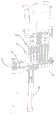
图2为本发明冲压模具实施例的结构示意图;Fig. 2 is the structural representation of stamping die embodiment of the present invention;
图3为本发明冲压模具实施例的第一剖视图;Fig. 3 is the first sectional view of stamping die embodiment of the present invention;
图4为图3中A处的局部放大图;Fig. 4 is a partial enlarged view of place A in Fig. 3;
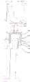
图5为本发明冲压模具实施例的第二剖视图;Fig. 5 is the second sectional view of stamping die embodiment of the present invention;
图6为图5中B处的局部放大图;Fig. 6 is a partial enlarged view of place B in Fig. 5;
图7为本发明中第二刀具的结构示意图;Fig. 7 is the structural representation of the second cutting tool in the present invention;
图8为本发明中第二刀具的剖视图;Fig. 8 is the cross-sectional view of the second cutter in the present invention;
图9为本发明冲压模具实施例的第三剖视图。Fig. 9 is a third cross-sectional view of the stamping die embodiment of the present invention.
附图标号说明:Explanation of reference numbers:
本发明目的实现、功能特点及优点将结合实施例,参照附图做进一步说明。The realization of the purpose, function and advantages of the present invention will be further described in conjunction with the embodiments and with reference to the accompanying drawings.
具体实施方式Detailed ways
下面将结合本发明实施例中的附图,对本发明实施例中的技术方案进行清楚、完整地描述,显然,所描述的实施例仅仅是本发明的一部分实施例,而不是全部的实施例。基于本发明中的实施例,本领域普通技术人员在没有作出创造性劳动前提下所获得的所有其他实施例,都属于本发明保护的范围。The following will clearly and completely describe the technical solutions in the embodiments of the present invention with reference to the accompanying drawings in the embodiments of the present invention. Obviously, the described embodiments are only part of the embodiments of the present invention, not all of them. Based on the embodiments of the present invention, all other embodiments obtained by persons of ordinary skill in the art without creative efforts fall within the protection scope of the present invention.
需要说明,若本发明实施例中有涉及方向性指示(诸如上、下、左、右、前、后……),则该方向性指示仅用于解释在某一特定姿态(如附图所示)下各部件之间的相对位置关系、运动情况等,如果该特定姿态发生改变时,则该方向性指示也相应地随之改变。It should be noted that if there is a directional indication (such as up, down, left, right, front, back...) in the embodiment of the present invention, the directional indication is only used to explain the position in a certain posture (as shown in the accompanying drawing). If the specific posture changes, the directional indication will also change accordingly.
另外,若本发明实施例中有涉及“第一”、“第二”等的描述,则该“第一”、“第二”等的描述仅用于描述目的,而不能理解为指示或暗示其相对重要性或者隐含指明所指示的技术特征的数量。由此,限定有“第一”、“第二”的特征可以明示或者隐含地包括至少一个该特征。另外,全文中出现的“和/或”的含义为,包括三个并列的方案,以“A和/或B为例”,包括A方案,或B方案,或A和B同时满足的方案。另外,各个实施例之间的技术方案可以相互结合,但是必须是以本领域普通技术人员能够实现为基础,当技术方案的结合出现相互矛盾或无法实现时应当认为这种技术方案的结合不存在,也不在本发明要求的保护范围之内。In addition, if there are descriptions involving "first", "second" and so on in the embodiments of the present invention, the descriptions of "first", "second" and so on are only for descriptive purposes, and should not be interpreted as indicating or implying Its relative importance or implicitly indicates the number of technical features indicated. Thus, the features defined as "first" and "second" may explicitly or implicitly include at least one of these features. In addition, the meaning of "and/or" appearing in the whole text includes three parallel schemes, taking "A and/or B as an example", including scheme A, scheme B, or schemes satisfying both A and B. In addition, the technical solutions of the various embodiments can be combined with each other, but it must be based on the realization of those skilled in the art. When the combination of technical solutions is contradictory or cannot be realized, it should be considered that the combination of technical solutions does not exist , nor within the scope of protection required by the present invention.
本发明提出一种冲压模具,用于将料带10冲压形成环形的隔膜片12,所述隔膜片12内部形成有镂空区域11。The present invention proposes a stamping die for stamping a
在本发明实施例中,如图2至图4所示,图2为本发明冲压模具一实施例的结构示意图;图3为本发明冲压模具一实施例的第一剖视图;图4为图3中A处的局部放大图。In the embodiment of the present invention, as shown in Fig. 2 to Fig. 4, Fig. 2 is a schematic structural view of an embodiment of the stamping die of the present invention; Fig. 3 is a first cross-sectional view of an embodiment of the stamping die of the present invention; Fig. 4 is Fig. 3 Partial enlarged view of A in the center.
该冲压模具包括支撑台20、压块30、冲模刀具以及真空机构,支撑台20具有支撑面21,支撑面21开设有第一冲模孔22和第二冲模孔23,压块30可运动地安装于支撑台20并位于支撑面21的一侧,以靠近或远离支撑面21,压块30用以将料带10压固于支撑面21上,以使料带10覆盖第一冲模孔22和第二冲模孔23。冲模刀具包括第一刀具41和第二刀具42,第二刀具42的裁切面积大于第一刀具41的裁切面积,第一刀具41可运动地安装于支撑台20并与第一冲模孔22相对设置,以伸入或退出第一冲模孔22,第二刀具42可运动地安装于支撑台20并与第二冲模孔23相对设置,以伸入或退出第二冲模孔23。第一刀具41用以在伸入第一冲模孔22时,从料带10上裁切出镂空区域11,第二刀具42用以在镂空区域11落入第二冲模孔23的投影时,伸入第二冲模孔23,以从料带10的镂空区域11外围裁取隔膜片12。The stamping die comprises a support table 20, a
其中,于压块30的运动方向上,第一冲模孔22在支撑面21上的轮廓线和压块30靠近支撑台20的一侧之间的最大距离为a,最小距离为b,满足a-b≤0.2。于压块30的运动方向上,第二冲模孔23在支撑面21上的轮廓线和压块30靠近支撑台20的一侧之间的最大距离为c,最小距离为d,满足最大距离c-d≤0.2。Wherein, in the moving direction of the
在冲压模具冲压的过程中,以第一冲模孔22和第一刀具41为例,如果第一冲模孔22在支撑面21上的轮廓线存在高度差,那么第一刀具41裁切料带10时会先和轮廓线高的一侧先接触,并局部裁切,此时下脚料局部分离于料带10,此时轮廓线低的一侧的料带10只有远离第一冲模孔22的一侧被压紧在支撑面21上,投影落在第一冲模孔22上的下脚料因被局部剪切而失去抵持作用,当第一刀具41裁切料带10轮廓线低的一侧时刀刃两侧受力不均衡,下脚料容易倾斜弯折,此时第一刀具41容易剪切形成毛刺,故本申请限定了第一冲模孔22在支撑面21上的轮廓线和压块30靠近支撑台20的一侧之间的最大距离和最小距离之间的差值,极大减少裁剪过程中毛刺的生成,从而保证隔膜片12的质量,利于下游产品的加工。In the stamping process of the stamping die, taking the
进一步地,在冲压模具零件的加工时,可以通过提高压块30和支撑台20的零件精度来控制第一冲模孔22和第二冲模孔23在支撑面21上的轮廓线到压块30靠近支撑台20的一侧的最大距离和最小距离之差,例如提高加工设备的加工精度,实际加工中多采用数控铣床进行加工,此时可以在精铣时通过调整铣刀的进给量以及进给速度来保证加工精度,或者在铣削完成之后再在磨床等平面加工精度更高的加工设备上再次进行精加工,但应当理解,本申请不对压块30和支撑台20的具体加工方式做出限定,以使第一冲模孔22和第二冲模孔23在支撑面21上的轮廓线到压块30靠近支撑台20的一侧的最大距离和最小距离之差达到设定范围内即可。Further, during the processing of stamping die parts, the contour lines of the
本实施例中,以环状隔膜片12为同心的圆环为例进行说明,应当理解,在本申请的其他实施例中,隔膜片12还可以是多边形的环状结构或者是偏心的圆环状,只需改变第一刀具41和第二刀具42的具体形状以及相对位置即可。In this embodiment, the
第二刀具42设有连通的过气孔421和过气通道422,过气孔421设于第二刀具42的刀刃端。真空机构安装于支撑台20,过气通道422和真空机构的真空口连通,真空机构用于调节过气通道422的真空度。当第二刀具42从料带上将隔膜片12裁剪下来之后,可以通过真空机构将隔膜片12吸固与第二刀具42上,从而实现隔膜片12的定位生产,后续可以直接将第二刀具42上的隔膜片12输送到后续的加工设备进行加工即可,无需定位上料。The
在本实施例中,支撑面21可以为支撑台20的顶面,也可以为支撑台20的侧面,本实施例以支撑面21为支撑台20的顶面为例。料带10可沿支撑面21运动,第一冲模孔22和第二冲模孔23沿料带10的运动方向排布,即料带10沿支撑面21运动时先经过第一冲模孔22再经过第二冲模孔23。压块30的运动方向垂直于支撑面21,例如压块30安装于支撑面21的上方,并可沿竖直方向做升降运动。压块30抵接于支撑面21时可压固料带10,压块30离开支撑面21时可松开料带10。冲压模具还包括安装于支撑台20的第一驱动装置,第一驱动装置用于驱动压块30运动,从而压块30可压住或松开料带10。In this embodiment, the
第一刀具41和第二刀具42安装于支撑面21的上方,并可沿第一冲模孔22和第二冲模孔23的轴向做升降运动。第一刀具41和第二刀具42呈柱状设置,第一刀具41的刀刃设于第一刀具41端面的周沿,第二刀具42的刀刃设于第二刀具42端面的周沿,第二刀具42的端面大于第一刀具41的端面,因此第二刀具42的裁切范围会大于第一刀具41的裁切范围。冲压模具还包括安装于支撑台20的第二驱动装置,第二驱动装置用于驱动第一刀具41和第二刀具42运动,从而使第一刀具41和第二刀具42裁切料带10。The
如图7和图8所示,图7为本发明中第二刀具42的结构示意图和剖视图;图8为本发明中第二刀具的剖视图。过气通道422沿第二刀具42的轴向延伸并贯穿第二刀具42远离其刀刃的一端。真空机构的真空口通过第二刀具42的顶端与过气通道422连通,真空机构通过调节过气通道422的真空度,可使过气孔421处产生负压,从而可吸附住被第二刀具42裁切下来的隔膜片12。过气孔421的数量可为多个,多个过气孔421沿第二刀具42的周向间隔设置,过气通道422的数量和位置与过气孔421对应,真空机构的出气口同时与多个过气通道422连通。如此,可增加对隔膜片12的吸附位置,使隔膜片12受力均衡,以提高对隔膜片12的吸附稳定性。As shown in FIG. 7 and FIG. 8 , FIG. 7 is a schematic structural view and a cross-sectional view of the
请一并参阅图1、图5和图6,图1为本发明中料带10被裁取出隔膜片12的过程示意图;图5为本发明冲压模具实施例的第二剖视图;图6为图5中B处的局部放大图。Please refer to Fig. 1, Fig. 5 and Fig. 6 together. Fig. 1 is a schematic diagram of the process of cutting out the
冲压模具工作时,料带10先经过第一冲模孔22,料带10盖住第一冲模孔22时压块30下降压住料带10,确保料带10受到冲压刀具的作用力时不会移位或者变形。压块30压住料带10后,第一刀具41伸入第一冲模孔22并捅破料带10,以从料带10上裁取下脚料;如此,料带10上先被第一刀具41裁出镂空区域11。When the stamping die works, the
料带10被裁出镂空区域11后,第一刀具41退出第一冲模孔22,压块30松开料带10,料带10继续朝向第二冲模孔23运动。当料带10运动至镂空区域11位于第二冲模孔23的投影内时,压块30再次压住料带10,此时第二刀具42伸入第二冲模孔23,并在料带10上镂空区域11的外围处裁取出环形的隔膜片12。After the
第二刀具42裁取得到隔膜片12时,真空机构开启以提高过气通道422的真空度,此时过气孔421对隔膜片12产生负压,从而隔膜片12可被吸附固定在第二刀具42上。隔膜片12被吸附固定住后,第二刀具42可将隔膜片12转移至电池盖帽的生产线上,并直接将隔膜片12层叠在电极片上。当然,在电极片之间的同轴度偏差允许的情况下,也可以是承载有电极片的承载治具直接输送到第二刀具42下方,然后真空机构关闭,过气孔421和过气通道422破真空,此时隔膜片12可直接落在电极片上。When the
第一冲模孔22和第二冲模孔23的数量可为多个,多个第一冲模孔22和第二冲模孔23均沿料带10的运动方向排布。第一刀具41和第二刀具42的数量和位置分别与第一冲模孔22和第二冲模孔23对应。如此,多个第一刀具41可同时运动,并一次性从料带10上裁切出多个镂空区域11。多个第二刀具42也可同时运动,并一次性从料带10上裁切出多个隔膜片12,从而提高冲压模具的生产效率。应当理解,多个第二刀具42均设有相应的过气孔421和过气通道422,真空机构可同时与多个第二刀具42的过气通道422连通。The number of the first die holes 22 and the second die holes 23 may be multiple, and the plurality of first die holes 22 and the second die holes 23 are arranged along the moving direction of the
第一刀具41从料带10上裁取的下脚料可直接从支撑台20掉出,也可通过设置集料结构统一收集。示例性的,如图4和图6所示,支撑台20内形成有集料槽24,集料槽24位于第一冲模孔22的下方并与第一冲模孔22连通,集料槽24用以盛接第一刀具41从料带10上裁下的下脚料。The leftovers cut by the
集料槽24可以收集每次从料带10下裁下的下脚料,方便后续统一处理。可以理解,当第一冲模孔22的数量为多个时,多个第一冲模孔22可与同一个集料槽24连通,以简化支撑台20的内部结构。The collecting
具体的,如图4和图6所示,冲压模具还包括可拆卸安装于支撑台20下方的集料件50,集料槽24的槽底开设有过料孔241,集料件50与过料孔241连通,集料件50用以盛接来自集料槽24的下脚料。下脚料进入集料槽24后,可进一步落入集料件50,如此,当集料件50内的下脚料积累到一定量时,用户可将集料件50拆下,以将下脚料倒出处理。Specifically, as shown in Figures 4 and 6, the stamping die also includes a collecting
由于下脚料的重量较小,难以在重力作用下自然落入集料件50,因此容易在集料槽24的局部位置堵塞。示例性的,如图4和图6所示,支撑台20内形成有吹气通道25,吹气通道25与集料槽24连通,冲压模具还包括气体驱动装置,气体驱动装置与吹气通道25连通,以将集料槽24内的下脚料吹向过料孔241。吹气通道25可贯穿集料槽24的侧槽壁,每次有下脚料掉入集料槽24后,气体驱动装置均可朝集料槽24吹气,以使下脚料在气流的作用下可被吹散或被吹至过料孔241处,由此,可避免下脚料造成集料槽24堵塞。Due to the small weight of the leftovers, it is difficult to naturally fall into the collecting
集料槽24的槽底可呈水平面,也可呈倾斜面。具体的,如图4和图6所示,集料槽24的槽底形成有斜坡面242,过料孔241设于斜坡面242的坡底处。由此,下脚料可在重力作用下沿斜坡面242滑向过料孔241,以提高对下脚料的收集效果。The groove bottom of collecting
示例性的,如图7所示,第二刀具42包括裁切部423和导向部424,裁切部423环设于导向部424,过气孔421设于裁切部423,导向部424凸出于裁切部423,导向部424的截面形状与第一刀具41的截面形状一致。导向部424用以在裁切部423从料带10的镂空区域11外围裁取隔膜片12之前,伸入料带10的镂空区域11,从而进一步保证隔膜片12的形状精度。Exemplarily, as shown in FIG. 7 , the
第二刀具42的刀刃设于裁切部423的外周沿处,导向部424的截面形状可与第一刀具41的截面形状一致。第二刀具42从料带10上裁切下隔膜片12后,导向部424穿设于隔膜片12,从而可在径向上对隔膜片12起到定位作用。当承载有电极片承载治具来到第二刀具42的下方时,导向部424的末端可先靠近电极片,而后隔膜片12再沿着导向部424落在电极片上,如此,可提高隔膜片12与电极片对位层叠时的位置准确性,以提高压合效果。The cutting edge of the
示例性的,如图2和图4所示,支撑面21设有走料槽26,走料槽26用以供料带10运动,第一冲模孔22和第二冲模孔23开设于走料槽26的槽底。压块30包括压接部31,压接部31用以将料带10压固于走料槽26的槽底。走料槽26沿第一冲模孔22和第二冲模孔23的排布方向延伸,料带10在走料槽26内走料,从而可方便对料带10进行限位,防止料带10偏离第一冲模孔22和第二冲模孔23。应当理解,此时支撑面21为走料槽26的槽底,第一冲模孔22和第二冲模孔23在支撑面21上的轮廓线即为在走料槽26槽底的轮廓线,此时计算轮廓线距离的基准面为压接部31的端面,即为压接部31靠近走料槽26的一侧。Exemplarily, as shown in Fig. 2 and Fig. 4, the
压块30可设于第一刀具41和第二刀具42的一侧,以在压固料带10的同时避位第一刀具41和第二刀具42。当然,压块30也可以通过其它的方式来避让第一刀具41和第二刀具42,例如,压块30可以设置为两个,两个压块30设于第一刀具41和第二刀具42排布方向的两侧,以实现对料带10的压固即可。The
示例性的,如图2和图4所示,冲压模具还包括安装件60,安装件60设置于压块30背离支撑台20的一侧,冲模刀具安装于安装件60,压块30开设有第一导通孔31和第二导通孔33,第一导通孔31与第一冲模孔22相对设置,第二导通孔33与第二冲模孔23相对设置,第一刀具41与第一导通孔31插接配合,第二刀具42与第二导通孔33插接配合。Exemplarily, as shown in FIG. 2 and FIG. 4 , the stamping die also includes a mounting
安装件60可运动地安装于支撑台20,安装件60运动时可带动第一刀具41和第二刀具42一起运动。第一导通孔31用以避位第一刀具41,第二导通孔33用以避位第二刀具42。可以理解,第一导通孔31和第二导通孔33还可分别对第一刀具41和第二刀具42起到导向作用,以防止第一刀具41和第二刀具42偏离第一冲模孔22和第二冲模孔23,从而可保证环形隔片的同轴度。The mounting
第一刀具41和第二刀具42伸入第一冲模孔22和第二冲模孔23时,安装件60和压块30可相互抵接,也可通过限位结构隔开。示例性的,如图9所示,图9为本发明冲压模具实施例的第三剖视图。冲压模具还包括限位件70,限位件70设有限位部71,压块30开设有过孔34,限位件70一端连接于安装件60、另一端插接于过孔34,限位部71抵持于压块30,从而限制第一刀具41和第二刀具42在第一导通孔31和第二导通孔33内的深入深度。因为在本申请实施例中,安装件60和压块30的截面相同,安装件60和压块30在贴合的情况下不易分离,限位件70的设置可避免安装件60和压块30直接接触,从而便于冲压模具的安装和调试。When the
本发明还提出一种加工设备,该加工设备包括冲压模具,该冲压模具的具体结构参照上述实施例,由于本加工设备采用了上述所有实施例的全部技术方案,因此至少具有上述实施例的技术方案所带来的所有有益效果,在此不再一一赘述。其中,加工设备用于将正极片和负极片隔着隔膜片12层叠压合形成电池盖帽。The present invention also proposes a processing device, which includes a stamping die. For the specific structure of the stamping die, refer to the above-mentioned embodiments. Since this processing device adopts all the technical solutions of all the above-mentioned embodiments, it has at least the technology of the above-mentioned embodiments. All beneficial effects brought by the scheme will not be repeated here. Wherein, the processing equipment is used for laminating and pressing the positive electrode sheet and the negative electrode sheet through the
本发明冲压模具中,通过控制第一冲模孔22和第二冲模孔23在支撑面21上的轮廓线到压块30靠近支撑台20的一侧的最大距离和最小距离之差,以使料带10贴合第一冲模孔22和第二冲模孔23在支撑面21上的轮廓线,从而保证料带10是绷紧固定在冲压模具上,避免第一冲模孔22和第二冲模孔23在支撑面21上的轮廓线的高度差太大而使刀具在轮廓线低处时料带10解除了绷紧状态,进而减少隔膜片12毛刺的生成。另一方面,本申请在第二刀具42设置过气孔421和过气通道422,并通过真空机构调节过气通道422的真空度,从而在第二刀具42从料带10上裁取下隔膜片12后,真空机构通过增大过气通道422的真空度,可使过气孔421将隔膜片12吸附住,从而将隔膜片12吸附定位在第二刀具42上,被吸附定位的隔膜片12可直接被转移至电池盖帽的生产线上投入电池盖帽的压合过程(例如直接被层叠在备好的电极片上);如此,在压合电池盖帽的过程中,隔膜片12可即裁即用,无需预先加工好,也无需重新上料定位,从而实现隔膜片在产线上的生产以及定位,进而可提高电池盖帽的生产效率。In the stamping die of the present invention, the difference between the maximum distance and the minimum distance from the contour line of the
以上所述仅为本发明的可选实施例,并非因此限制本发明的专利范围,凡是在本发明的发明构思下,利用本发明说明书及附图内容所作的等效结构变换,或直接/间接运用在其他相关的技术领域均包括在本发明的专利保护范围内。The above descriptions are only optional embodiments of the present invention, and do not limit the patent scope of the present invention. Under the inventive concept of the present invention, the equivalent structural transformation made by using the description of the present invention and the contents of the accompanying drawings, or direct/indirect Application in other related technical fields is included in the patent protection scope of the present invention.
Claims (10)
Translated fromChinesePriority Applications (1)
| Application Number | Priority Date | Filing Date | Title |
|---|---|---|---|
| CN202310056209.9ACN116141428A (en) | 2023-01-18 | 2023-01-18 | Stamping die and processing equipment |
Applications Claiming Priority (1)
| Application Number | Priority Date | Filing Date | Title |
|---|---|---|---|
| CN202310056209.9ACN116141428A (en) | 2023-01-18 | 2023-01-18 | Stamping die and processing equipment |
Publications (1)
| Publication Number | Publication Date |
|---|---|
| CN116141428Atrue CN116141428A (en) | 2023-05-23 |
Family
ID=86338424
Family Applications (1)
| Application Number | Title | Priority Date | Filing Date |
|---|---|---|---|
| CN202310056209.9APendingCN116141428A (en) | 2023-01-18 | 2023-01-18 | Stamping die and processing equipment |
Country Status (1)
| Country | Link |
|---|---|
| CN (1) | CN116141428A (en) |
Cited By (1)
| Publication number | Priority date | Publication date | Assignee | Title |
|---|---|---|---|---|
| CN116141427A (en)* | 2023-01-18 | 2023-05-23 | 安徽国研新能电芯技术有限公司 | Stamping device and processing equipment |
Citations (7)
| Publication number | Priority date | Publication date | Assignee | Title |
|---|---|---|---|---|
| US5704264A (en)* | 1995-08-31 | 1998-01-06 | Kimberly-Clark Worldwide, Inc. | Cutting die with elevated stripping land |
| CN105643718A (en)* | 2016-04-11 | 2016-06-08 | 詹静 | Dual-cutter mold base automatic cutting machine and control method thereof |
| CN108858456A (en)* | 2018-06-04 | 2018-11-23 | 苏州天立达胶粘制品有限公司 | A kind of dise knife die cutting process method |
| CN109664368A (en)* | 2019-01-28 | 2019-04-23 | 昆山琨明电子科技有限公司 | Full-automatic punching press braid all-in-one machine |
| CN116141427A (en)* | 2023-01-18 | 2023-05-23 | 安徽国研新能电芯技术有限公司 | Stamping device and processing equipment |
| CN219563425U (en)* | 2023-01-18 | 2023-08-22 | 安徽国研新能电芯技术有限公司 | Stamping device and processing equipment |
| CN220994727U (en)* | 2023-01-18 | 2024-05-24 | 安徽国研新能电芯技术有限公司 | Stamping die and processing equipment |
- 2023
- 2023-01-18CNCN202310056209.9Apatent/CN116141428A/enactivePending
Patent Citations (7)
| Publication number | Priority date | Publication date | Assignee | Title |
|---|---|---|---|---|
| US5704264A (en)* | 1995-08-31 | 1998-01-06 | Kimberly-Clark Worldwide, Inc. | Cutting die with elevated stripping land |
| CN105643718A (en)* | 2016-04-11 | 2016-06-08 | 詹静 | Dual-cutter mold base automatic cutting machine and control method thereof |
| CN108858456A (en)* | 2018-06-04 | 2018-11-23 | 苏州天立达胶粘制品有限公司 | A kind of dise knife die cutting process method |
| CN109664368A (en)* | 2019-01-28 | 2019-04-23 | 昆山琨明电子科技有限公司 | Full-automatic punching press braid all-in-one machine |
| CN116141427A (en)* | 2023-01-18 | 2023-05-23 | 安徽国研新能电芯技术有限公司 | Stamping device and processing equipment |
| CN219563425U (en)* | 2023-01-18 | 2023-08-22 | 安徽国研新能电芯技术有限公司 | Stamping device and processing equipment |
| CN220994727U (en)* | 2023-01-18 | 2024-05-24 | 安徽国研新能电芯技术有限公司 | Stamping die and processing equipment |
Cited By (1)
| Publication number | Priority date | Publication date | Assignee | Title |
|---|---|---|---|---|
| CN116141427A (en)* | 2023-01-18 | 2023-05-23 | 安徽国研新能电芯技术有限公司 | Stamping device and processing equipment |
Similar Documents
| Publication | Publication Date | Title |
|---|---|---|
| CN220994727U (en) | Stamping die and processing equipment | |
| CN109482711B (en) | High-speed stamping progressive die for stator and rotor punching sheet of motor | |
| CN116141428A (en) | Stamping die and processing equipment | |
| CN206702064U (en) | A kind of backboard punching trimming marks mould | |
| CN106346067A (en) | Wire connecting and slitting machine for large-sized pole piece of lithium-ion battery | |
| CN209124686U (en) | A kind of multi items material blanking stepping punching mould | |
| CN108097784B (en) | Continuous blanking die for shell parts | |
| CN207887700U (en) | A kind of continuous blanking mold of housing component | |
| CN209318531U (en) | The high speed stamping progressive die of motor stator&rotor blanking piece | |
| CN211250331U (en) | Scrap punching die | |
| CN211613983U (en) | Multi-material punching and laminating forming die | |
| CN211539215U (en) | Hinge shaping lower die structure | |
| CN110788202A (en) | A multi-material punching and laminating mold | |
| CN207941851U (en) | A kind of novel side piercing die | |
| CN201880796U (en) | Punching cut die for left and right rear wheel covers of automobile | |
| CN215431264U (en) | A concentrate and inhale useless structure for stamping die | |
| CN221697187U (en) | Carving knife mold | |
| CN217570400U (en) | Stamping die of atomizing piece | |
| CN206445874U (en) | A kind of insulating sheet forming mold | |
| CN204398026U (en) | Mould cut by the flat cutter of rolling material | |
| CN219985927U (en) | Whole board dashes waste material cutter structure | |
| CN206643211U (en) | Audiphone shields shell Blanking progressive die | |
| CN212121349U (en) | Die set | |
| CN210045840U (en) | Partition plate mould with one-outlet two-function | |
| CN213165714U (en) | Device for rapid die cutting |
Legal Events
| Date | Code | Title | Description |
|---|---|---|---|
| PB01 | Publication | ||
| PB01 | Publication | ||
| SE01 | Entry into force of request for substantive examination | ||
| SE01 | Entry into force of request for substantive examination |