CN116138708A - Insertion part and endoscope - Google Patents
Insertion part and endoscopeDownload PDFInfo
- Publication number
- CN116138708A CN116138708ACN202310178510.7ACN202310178510ACN116138708ACN 116138708 ACN116138708 ACN 116138708ACN 202310178510 ACN202310178510 ACN 202310178510ACN 116138708 ACN116138708 ACN 116138708A
- Authority
- CN
- China
- Prior art keywords
- elastic member
- bending section
- end seat
- optical fiber
- radial line
- Prior art date
- Legal status (The legal status is an assumption and is not a legal conclusion. Google has not performed a legal analysis and makes no representation as to the accuracy of the status listed.)
- Granted
Links
Images


Classifications
- A—HUMAN NECESSITIES
- A61—MEDICAL OR VETERINARY SCIENCE; HYGIENE
- A61B—DIAGNOSIS; SURGERY; IDENTIFICATION
- A61B1/00—Instruments for performing medical examinations of the interior of cavities or tubes of the body by visual or photographical inspection, e.g. endoscopes; Illuminating arrangements therefor
- A61B1/005—Flexible endoscopes
- A61B1/0051—Flexible endoscopes with controlled bending of insertion part
- A61B1/0055—Constructional details of insertion parts, e.g. vertebral elements
- A—HUMAN NECESSITIES
- A61—MEDICAL OR VETERINARY SCIENCE; HYGIENE
- A61B—DIAGNOSIS; SURGERY; IDENTIFICATION
- A61B1/00—Instruments for performing medical examinations of the interior of cavities or tubes of the body by visual or photographical inspection, e.g. endoscopes; Illuminating arrangements therefor
- A61B1/00064—Constructional details of the endoscope body
- A61B1/00071—Insertion part of the endoscope body
- A—HUMAN NECESSITIES
- A61—MEDICAL OR VETERINARY SCIENCE; HYGIENE
- A61B—DIAGNOSIS; SURGERY; IDENTIFICATION
- A61B1/00—Instruments for performing medical examinations of the interior of cavities or tubes of the body by visual or photographical inspection, e.g. endoscopes; Illuminating arrangements therefor
- A61B1/005—Flexible endoscopes
- A61B1/0051—Flexible endoscopes with controlled bending of insertion part
- A61B1/0057—Constructional details of force transmission elements, e.g. control wires
- A—HUMAN NECESSITIES
- A61—MEDICAL OR VETERINARY SCIENCE; HYGIENE
- A61B—DIAGNOSIS; SURGERY; IDENTIFICATION
- A61B1/00—Instruments for performing medical examinations of the interior of cavities or tubes of the body by visual or photographical inspection, e.g. endoscopes; Illuminating arrangements therefor
- A61B1/005—Flexible endoscopes
- A61B1/008—Articulations
- A—HUMAN NECESSITIES
- A61—MEDICAL OR VETERINARY SCIENCE; HYGIENE
- A61B—DIAGNOSIS; SURGERY; IDENTIFICATION
- A61B1/00—Instruments for performing medical examinations of the interior of cavities or tubes of the body by visual or photographical inspection, e.g. endoscopes; Illuminating arrangements therefor
- A61B1/005—Flexible endoscopes
- A61B1/01—Guiding arrangements therefore
Landscapes
- Health & Medical Sciences (AREA)
- Life Sciences & Earth Sciences (AREA)
- Surgery (AREA)
- Biomedical Technology (AREA)
- Medical Informatics (AREA)
- Optics & Photonics (AREA)
- Pathology (AREA)
- Radiology & Medical Imaging (AREA)
- Biophysics (AREA)
- Engineering & Computer Science (AREA)
- Physics & Mathematics (AREA)
- Heart & Thoracic Surgery (AREA)
- Nuclear Medicine, Radiotherapy & Molecular Imaging (AREA)
- Molecular Biology (AREA)
- Animal Behavior & Ethology (AREA)
- General Health & Medical Sciences (AREA)
- Public Health (AREA)
- Veterinary Medicine (AREA)
- Rehabilitation Therapy (AREA)
- Endoscopes (AREA)
Abstract
Description
Translated fromChinese技术领域technical field
本申请涉及医疗器械技术领域,尤其涉及一种插入部及内窥镜。The present application relates to the technical field of medical devices, in particular to an insertion part and an endoscope.
背景技术Background technique
随着医疗技术的不断发展,内窥镜在疾病的诊疗过程中得到了广泛应用。在使用内窥镜的过程中,可通过操控手柄对插入部的前端朝向进行控制,从而获取到目标部位的影像信息。With the continuous development of medical technology, endoscopy has been widely used in the diagnosis and treatment of diseases. During the use of the endoscope, the orientation of the front end of the insertion part can be controlled by operating the handle, so as to acquire image information of the target site.
在相关技术中,可通过器械管拉拽前端座而实现前端组件与主动弯曲段的预紧固定组装;同时,为了进一步地简化插入部的结构,可配置光纤束牵拉前端座实现主动弯曲段的弯曲动作。但是,此种结构布局的插入部在使用过程中,前端座与主动弯曲段间易出现相对偏斜的情况,二者在对接处甚至会出现较为明显的机械损伤。In the related technology, the front-end component and the active bending section can be pre-tightened and fixed by pulling the front-end seat through the instrument tube; at the same time, in order to further simplify the structure of the insertion part, an optical fiber bundle can be configured to pull the front-end seat to realize the active bending section bending action. However, during the use of the insertion portion with such a structural layout, relative deflection tends to occur between the front end seat and the active bending section, and obvious mechanical damage may even occur at the joint of the two.
发明内容Contents of the invention
本申请实施例提供一种插入部及内窥镜,能够优化前端座与主动弯曲段间的受力分布。The embodiment of the present application provides an insertion part and an endoscope, which can optimize the force distribution between the front end seat and the active bending section.
为了解决上述问题,本申请实施例采用下述技术方案:In order to solve the above problems, the embodiment of the present application adopts the following technical solutions:
第一方面,本申请实施例提供一种插入部,用于内窥镜。所述插入部包括前端座、主动弯曲段、器械管、至少一个弹性件和至少一根光纤束,所述前端座经由所述器械管拉拽而预紧抵接于所述主动弯曲段的远端;In a first aspect, the embodiment of the present application provides an insertion part for an endoscope. The insertion part includes a front end seat, an active bending section, an instrument tube, at least one elastic member and at least one optical fiber bundle, and the front end seat is preloaded against the distal end of the active bending section by being pulled by the instrument tube. end;
所述光纤束的远端固定安装于所述前端座,所述光纤束能够向所述前端座施加弯曲牵引力,所述弯曲牵引力用于实现所述主动弯曲段的弯曲;所述前端座的第一抵接面和/或所述主动弯曲段的第二抵接面设有所述弹性件,其中,所述至少一个弹性件包括第一弹性件,在所述插入部的周向上,所述第一弹性件位于所述光纤束的偏置侧。The distal end of the optical fiber bundle is fixedly installed on the front end seat, and the optical fiber bundle can apply a bending traction force to the front end seat, and the bending traction force is used to realize the bending of the active bending section; the first end of the front end seat An abutment surface and/or the second abutment surface of the active bending section is provided with the elastic member, wherein the at least one elastic member includes a first elastic member, and in the circumferential direction of the insertion part, the A first elastic member is located on a biased side of the fiber bundle.
第二方面,本申请实施例提供一种内窥镜,包括手柄以及本申请实施例第一方面所述的插入部,所述手柄与所述插入部连接。In a second aspect, an embodiment of the present application provides an endoscope, including a handle and the insertion part described in the first aspect of the embodiment of the present application, the handle is connected to the insertion part.
本申请实施例采用的技术方案能够达到以下有益效果:The technical solution adopted in the embodiment of the present application can achieve the following beneficial effects:
在本申请实施例公开的插入部及内窥镜中,在通过光纤束拉拽前端座带动主动弯曲段实现弯曲动作的过程中,第一弹性件能够在光纤束的偏置侧通过弹性变形消耗部分弯曲牵引力,从而缓解前端座与主动弯曲段间的受力分布不均的问题,避免二者间出现相对偏斜的情况,提升了插入部的同轴性,并能够防止因应力集中而导致的机械损伤。In the insertion part and the endoscope disclosed in the embodiments of the present application, in the process of pulling the front end seat by the fiber bundle to drive the active bending section to realize the bending action, the first elastic member can be consumed by elastic deformation on the biased side of the fiber bundle. Partial bending traction, so as to alleviate the problem of uneven force distribution between the front seat and the active bending section, avoid the relative deflection between the two, improve the coaxiality of the insertion part, and prevent the stress concentration from causing of mechanical damage.
同时,第一弹性件在前端座与主动弯曲段间被挤压而储能,第一弹性件的弹性特性使得其向主动弯曲段施加回弹力,该回弹力会叠加至原弯曲牵引力,从而强化拉拽主动弯曲段实现弯曲动作的拉拽作用,提升了主动弯曲段的控制灵敏度。At the same time, the first elastic member is squeezed between the front end seat and the active bending section to store energy. The elastic characteristics of the first elastic member make it apply a rebound force to the active bending section, and the rebound force will be superimposed on the original bending traction force, thereby strengthening the Pulling the active bending section realizes the pulling effect of the bending action, which improves the control sensitivity of the active bending section.
再者,第一弹性件施加的回弹力还能够强化前端座与主动弯曲段间的预紧作用,从而提升了前端座与主动弯曲段间的抵接稳定性。Furthermore, the resilience exerted by the first elastic member can also strengthen the pre-tightening effect between the front end seat and the active bending section, thereby improving the contact stability between the front end seat and the active bending section.
附图说明Description of drawings
此处所说明的附图用来提供对本申请的进一步理解,构成本申请的一部分,本申请的示意性实施例及其说明用于解释本申请,并不构成对本申请的不当限定。The drawings described here are used to provide a further understanding of the application and constitute a part of the application. The schematic embodiments and descriptions of the application are used to explain the application and do not constitute an improper limitation to the application.
在附图中:In the attached picture:
图1为本申请一些实施例公开的插入部的结构示意图;Fig. 1 is a schematic structural diagram of an insertion part disclosed in some embodiments of the present application;
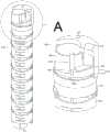
图2为本申请第一实施例公开的插入部的结构示意图(隐藏部分前端座)以及其中A处的局部放大图;Fig. 2 is a schematic structural view of the insertion part disclosed in the first embodiment of the present application (the front end seat is hidden) and a partial enlarged view of A;
图3为本申请第二实施例公开的插入部的结构示意图(隐藏部分前端座)以及其中B处的局部放大图;Fig. 3 is a schematic structural view of the insertion part disclosed in the second embodiment of the present application (the front end seat is hidden) and a partial enlarged view of B therein;
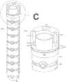
图4为本申请第三实施例公开的插入部的结构示意图(隐藏部分前端座)以及其中C处的局部放大图;Fig. 4 is a schematic structural view of the insertion part disclosed in the third embodiment of the present application (the front end seat is hidden) and a partial enlarged view of C;
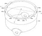
图5为本申请第四实施例公开的远端蛇骨的结构示意图;Fig. 5 is a schematic structural view of the distal snake bone disclosed in the fourth embodiment of the present application;
图6为本申请第五实施例公开的插入部中弹性件的布局示意图;Fig. 6 is a schematic layout diagram of the elastic member in the insertion part disclosed in the fifth embodiment of the present application;
图7为本申请第六实施例公开的插入部的结构示意图(隐藏部分前端座)以及其中D处的局部放大图。Fig. 7 is a schematic structural view of the insertion part disclosed in the sixth embodiment of the present application (the front end seat is hidden) and a partial enlarged view of D therein.
附图标记说明:Explanation of reference signs:
100-前端组件、110-前端座、111-主体、111a-第一台阶部、112-隔板、120-摄像头、130-光导件、140-电路板、100-front-end assembly, 110-front-end seat, 111-main body, 111a-first step, 112-partition, 120-camera, 130-light guide, 140-circuit board,
200-主动弯曲段、210-远端蛇骨、211-第二台阶部、212-第二抵接面、220-衔接蛇骨、200-active bending section, 210-distal snake bone, 211-second step, 212-second abutment surface, 220-connecting snake bone,
300a-第一弹性件、300b-第二弹性件、C-变形缝隙、300a-first elastic member, 300b-second elastic member, C-deformation gap,
400-器械管、500-第一光纤束。400-instrument tube, 500-first optical fiber bundle.
具体实施方式Detailed ways
为使本申请的目的、技术方案和优点更加清楚,下面将结合本申请具体实施例及相应的附图对本申请技术方案进行清楚、完整地描述。显然,所描述的实施例仅是本申请一部分实施例,而不是全部的实施例。基于本申请中的实施例,本领域普通技术人员在没有做出创造性劳动前提下所获得的所有其他实施例,都属于本申请保护的范围。In order to make the purpose, technical solution and advantages of the present application clearer, the technical solution of the present application will be clearly and completely described below in conjunction with specific embodiments of the present application and corresponding drawings. Apparently, the described embodiments are only some of the embodiments of the present application, rather than all the embodiments. Based on the embodiments in this application, all other embodiments obtained by persons of ordinary skill in the art without making creative efforts belong to the scope of protection of this application.
在本申请的各实施例中,“近端”和“远端”是指内窥镜及其配件在使用环境下,相对于使用者的远近位置而言,其中,距离使用者较近的一端拟定为“近端”,距离使用者较远的一端拟定为“远端”。In each embodiment of the present application, "proximal end" and "distal end" refer to the far and near positions of the endoscope and its accessories relative to the user in the use environment, among which, the end that is closer to the user It is designated as "near end", and the end farther away from the user is designated as "far end".
以下结合附图,详细说明本申请各个实施例公开的技术方案。The technical solutions disclosed in various embodiments of the present application will be described in detail below with reference to the accompanying drawings.
在相关技术中,发明人利用预紧安装器械管的手段,通过器械管向前端座施加牵引力,从而将前端座预紧抵接在主动弯曲段的远端,以提升插入部的装配效率。同时,发明人在上述方案基础上为了进一步地简化插入部的结构,通过配置光纤束牵拉前端座实现主动弯曲段的弯曲动作,以替代传统的牵引绳。但是,上述插入部在使用过程中,前端组件与主动弯曲段间易出现相对偏斜的情况,具体至少可表现为插入部的同轴性较差,同时,前端座与主动弯曲段远端间的对接处存在较为明显的机械损伤。In the related art, the inventor uses the means of pre-tightening the instrument tube to apply traction to the front-end seat through the instrument tube, so that the front-end seat is pre-tightened against the distal end of the active bending section, so as to improve the assembly efficiency of the insertion part. At the same time, in order to further simplify the structure of the insertion part on the basis of the above solution, the inventor realized the bending action of the active bending section by configuring the fiber bundle pulling front end seat to replace the traditional pulling rope. However, during the use of the above-mentioned insertion part, relative deflection tends to occur between the front-end assembly and the active bending section. Specifically, at least it can be shown that the coaxiality of the insertion part is poor. There is obvious mechanical damage at the butt joint.
进过进一步研究,发明人发现上述问题是由于光纤束偏置设置所造成的。具体而言,在前端座的布局中,器械管和光纤束都需要占据前端座横截面上的布局空间,光纤束为了避让器械管会布置前端座靠近边缘的区域,在通过光纤束牵拉前端座而实现主动弯曲段的弯曲动作的过程中,光纤束会向前端座施加偏置的牵引力,如此会导致前端座与主动弯曲段在对接处的受力分布不均,从而导致二者间的相对偏斜;同时,正因为二者间的受力分布不均匀,受力较大的部位则易因应力集中而出现机械损伤。After further research, the inventors found that the above-mentioned problem is caused by the bias setting of the fiber bundle. Specifically, in the layout of the front-end seat, both the instrument tube and the fiber bundle need to occupy the layout space on the cross-section of the front-end seat. In order to avoid the instrument tube, the fiber bundle will be arranged near the edge of the front-end seat. In the process of realizing the bending action of the active bending section, the optical fiber bundle will apply a biased traction force to the front-end seat, which will lead to uneven force distribution at the joint between the front-end seat and the active bending section, resulting in a gap between the two Relatively deflected; at the same time, because of the uneven force distribution between the two, the parts with greater stress are prone to mechanical damage due to stress concentration.
对此,本申请的一些实施例提供一种插入部,用于内窥镜。For this, some embodiments of the present application provide an insertion part for an endoscope.
请参见图1~图7,本申请实施例公开的插入部包括前端座110、主动弯曲段200、器械管400、至少一个弹性件和至少一根光纤束,前端座110经由器械管400拉拽而预紧抵接于主动弯曲段200的远端。Please refer to FIGS. 1 to 7 , the insertion part disclosed in the embodiment of the present application includes a
具体而言,插入部包括前端组件100,前端座110是前端组件100的基础结构,其为摄像头120、器械管400、光纤束和电路板140等提供了安装基础,当然,其还能够对这些结构起到保护作用。Specifically, the insertion part includes the front-
摄像头120可设于前端座110的前端面一侧,以在插入部进入人体腔道的情况下对目标部位(例如病灶)进行拍摄。至少一根光纤束可包括照明用的第一光纤束500,以为前端组件100朝向的区域进行照明。电路板140能够为摄像头120供电,也用于实现信号交互。当然,在一些实施例中,至少一根光纤束还可包括拍摄用的第二光纤束,其与摄像头120连接,以进行信号交互。器械管400用于向人体腔道内送入处置器械,以及抽吸组织液。可选地,如图1~图4所示,插入部还可包括光导件130,其设于光纤束的远端,以便于在前端座110远端面实现导光。The
前端组件100的各结构可通过多种方式实现加工组配,如图2所示,前端座110包括主体111和隔板112,隔板112可在主体111内部隔离出安装空间,摄像头120、电路板140、光纤束和器械管400的远端均可设于安装空间中,通过向安装空间内注胶实现主体111、隔板112、摄像头120、电路板140、光纤束和器械管400远端等结构的一体成型。在另外的实施例中,前端组件100以及器械管400远端可通过一体注塑成型实现加工组配。Each structure of the front-
关于主动弯曲段200,其作为插入部的弯曲动作主体111,可以采用蛇骨式结构,也可以采用一体切割式结构,本申请的实施例对其类型不做限制。Regarding the
在主动弯曲段200为蛇骨式结构的实施例中,前端座110与远端蛇骨210的远端一侧预紧抵接;主动弯曲段200还包括多个依次转动连接的衔接蛇骨220,处于最前端的衔接蛇骨220与远端蛇骨210转动连接,且随远端蛇骨210转动。具体地,主动弯曲段200是通过光纤束拉拽而实现弯曲动作。In the embodiment in which the
可以理解,由于器械管400与前端座110固定连接,则器械管400可将作用力传导至前端座110上。在本申请的实施例中,器械管400适于承受预紧牵引力F(可参见附图中的虚线箭头),并通过将该预紧牵引力F传导至前端座110上,在前端组件100与主动弯曲段200的装配过程中,使前端座110与主动弯曲段200的远端相互靠近,并拉拽前端座110的近端一侧与主动弯曲段200的远端抵接。当然,在预紧牵引力F传导至前端座110的过程中,预紧牵引力F可能会存在损耗,也即前端座110的受力小于预紧牵引力F或大致为预紧牵引力F,但为了便于行文,后续仍以前端座110受到预紧牵引力F进行说明。It can be understood that since the
需要说明的是,本申请实施例的器械管400适于承受的预紧牵引力F能够使前端座110预紧抵接在主动弯曲段200的远端,具体能够达到前端座110的近端一侧与主动弯曲段200的远端实现预紧固定的效果,使二者在对接处能够承受一定的外部作用力而不脱离,也就是说,该预紧牵引力F使得前端座110的近端一侧与主动弯曲段200的远端之间具有一定的连接可靠性。当然,器械管400在其近端一侧可进行预紧安装,以使器械管400能够保持较为张紧的状态而确保其始终能够拉拽前端座110预紧抵接在主动弯曲段200的远端。It should be noted that the pretension traction force F that the
基于上述分析可知,本申请实施例的前端组件100在与主动弯曲段200进行装配时,在器械管400穿设于主动弯曲段200的情况下,通过拉拽器械管400即可向前端座110施加预紧牵引力F,并拉拽前端座110预紧抵接在主动弯曲段200的远端,当然,在拉拽过程中,可适时地调节前端座110与主动弯曲段200的对正情况。Based on the above analysis, it can be seen that when the
与此同时,光纤束的远端固定安装于前端座110,光纤束能够向前端座110施加弯曲牵引力,弯曲牵引力用于实现主动弯曲段200的弯曲;前端座110的第一抵接面和/或主动弯曲段200的第二抵接面212设有弹性件,其中,至少一个弹性件包括第一弹性件300a,在插入部的周向上,第一弹性件300a位于光纤束的偏置侧。At the same time, the far end of the fiber bundle is fixedly mounted on the
可以理解,光纤束与前端座110的固定连接部位相当于一个施力点,其能够将光纤束传递的弯曲牵引力施加给前端座110,经由前端座110带动主动弯曲段200实现弯曲动作。It can be understood that the fixed connection between the fiber bundle and the front-
关于弹性件的数量,插入部可包括多个弹性件,也可仅包括一个弹性件;在前端座110的抵接面和主动弯曲段200的抵接面中,可以仅一者设有弹性件,也可两者均设有弹性件,如图2所示,弹性件设于主动弯曲段200的第二抵接面212上。其中,前端座110的第一抵接面是指其与主动弯曲段200预紧抵接的抵接面,主动弯曲段200的第二抵接面212是指其与前端座110预紧抵接的抵接面。Regarding the number of elastic pieces, the insertion part may include multiple elastic pieces, or only one elastic piece; only one of the abutment surfaces of the
在此种结构布局下,弹性件能够在前端座110与主动弯曲段200的相对抵接面之间起到弹性支撑作用。Under such a structural layout, the elastic member can play an elastic supporting role between the opposing surfaces of the
具体地,在前端座110经由器械管400施加的预紧牵引力的作用下而预紧抵接于主动弯曲段200的情况下,通过光纤束向前端座110施加弯曲牵引力时,弯曲牵引力会传递至第一弹性件300a,第一弹性件300a在前端座110与主动弯曲段200之间被压缩,第一弹性件300a能够通过弹性形变吸收前端座110在光纤束的偏置侧受到的弯曲牵引力而进行储能,可见,本申请实施例的第一弹性件300a能够消耗部分前端座110在光纤束偏置侧受到的弯曲牵引力,如此在一定程度上缓解前端座110与主动弯曲段200间的受力分布不均的问题,从而避免二者间出现相对偏斜的情况。Specifically, when the front-
需要说明的是,由于本申请实施例的前端座110与主动弯曲段200是通过预紧抵接的方式实现固定装配,若弯曲牵引力的偏置程度过大则容易出现偏斜情况,而第一弹性件300a的作用在于通过调节前端座110与主动弯曲段200间的受力分布而缓解相对偏斜的情况,并非阻碍弯曲牵引力拉拽主动弯曲段200实现弯曲动作。It should be noted that since the
同时,由于第一弹性件300a在前端座110与主动弯曲段200远端间被挤压而储能,第一弹性件300a的弹性特性决定了其会通过释能而向前端座110或主动弯曲段200施加回弹力,而在前端座110与主动弯曲段200预紧抵接的情况下,作用于主动弯曲段200的回弹力会叠加至原弯曲牵引力,也即强化了拉拽主动弯曲段200实现弯曲动作的拉拽作用,由此能够提升主动弯曲段200的控制灵敏度。At the same time, since the first
此外,在前端座110与主动弯曲段200预紧抵接的情况下,二者间的预紧作用除了器械管400向前端座110施加的预紧牵引力,还叠加了第一弹性件300a的回弹力,如此可显著地提升前端座110与主动弯曲段200间的抵接稳定性。In addition, when the front-
相较于相关技术,本申请实施例公开的插入部通过在前端座110与主动弯曲段200的抵接面间设置弹性件,其在前端座110与主动弯曲段200之间且位于光纤束偏置的一侧起到弹性支撑作用,在通过光纤束拉拽前端座110实现主动弯曲段200的弯曲动作的过程中,能够缓解二者间的受力不均的问题,从而提升了插入部的同轴性,也能够防止因应力集中而出现机械损伤;同时,弹性件的回弹特性能够强化拉拽主动弯曲段200弯曲的弯曲作用力,以提升主动弯曲段200的控制灵敏度,且还能够强化前端座110与主动弯曲段200间的预紧作用,从而提升二者间的抵接稳定性,也即提升二者间的装配可靠性。Compared with the related technology, the insertion part disclosed in the embodiment of the present application is provided with an elastic member between the abutting surface of the
在本申请的实施例中,弹性件的类型可以有多种,举例来说,其可以为诸如弹簧等独立的构件。In the embodiments of the present application, there may be various types of the elastic member, for example, it may be an independent component such as a spring.
在另外的实施例中,如图2~图7所示,弹性件一体成型于前端座110或主动弯曲段200,这样可减少插入部的构件数量,能够减少加工组配工序,同时,与前端座110或主动弯曲段200一体成型的弹性件的安装强度更优。In other embodiments, as shown in Figures 2 to 7, the elastic member is integrally formed on the
进一步地,为了确保弹性件具备可靠的弹性特性,弹性件与前端座110或主动弯曲段200间设有变形缝隙C。可以理解,变形缝隙C能够减小弹性件的刚度,使得弹性件更易于实现弹性变形而在前端座110与主动弯曲段200间起到弹性支撑作用。Further, in order to ensure that the elastic member has reliable elastic properties, a deformation gap C is provided between the elastic member and the
在本申请的实施例中,第一弹性件300a的布局方式有多种,如图2所示,插入部的第一径线l1上设有第一弹性件300a,第一径线l1通过插入部的轴线和光纤束的轴线。如此布局下,可在光纤束施加的弯曲牵引力的最大偏置力分量处起到弹性支撑作用,从而缓解前端座110与主动弯曲段200间的相对倾斜情况。In the embodiment of the present application, there are various layouts of the first
和/或,第一径线l1的两侧对称设置有第一弹性件300a,第一径线l1通过插入部的轴线和光纤束的轴线。可以理解,本申请的实施例可仅在第一径线l1的两侧设置第一弹性件300a,如图3所示;当然,也可同时在第一径线l1上以及第一径线l1的两侧都设有第一弹性件300a,如图5所示。And/or, the first
分布于第一径线l1两侧的多个第一弹性件300a能够共同起到弹性支撑作用,减少了单个第一弹性件300a的应力损耗;分布于第一径线l1两侧的第一弹性件300a也能分担设于第一径线l1上的第一弹性件300a受到的弯曲牵引力,避免设于第一径线l1上的第一弹性件300a因应力集中而受损。The multiple first
如图6所示,在本申请的一些实施例中,第一弹性件300a为多个,在插入部的周向且背离插入部的第一径线l1的方向上,第一弹性件300a的高度逐渐减小;第一径线l1通过插入部的轴线和光纤束的轴线。例如,在图6示出的实施例中,位于第一径线l1左侧的第一弹性件300a的高度小于位于第一径线l1上的第一弹性件300a,具体可参考图6中的水平标识虚线。As shown in FIG. 6 , in some embodiments of the present application, there are multiple first
需要说明的是,图6示出了一种插入部中弹性件的布局示意图,其展示的弹性件位于前端座110或主动弯曲段200的周向上,为了便于体现出不同弹性件间的差异,遂将其在二维面内展示。It should be noted that FIG. 6 shows a schematic layout diagram of the elastic elements in the insertion part, which shows that the elastic elements are located in the circumferential direction of the
可以理解,在插入部的周向且背离第一径线l1的方向上,光纤束拉拽前端座110的弯曲牵引力的偏置力分量会逐渐减小,在该实施例中,在插入部的周向上分布的第一弹性件300a存在高度差,越靠近插入部的第一径线l1的第一弹性件300a能够更早地在前端座110与主动弯曲段200间实现弹性支撑作用,其可以通过更大的弹性变形来消耗弯曲牵引力的偏置力分量,相较远离第一径线l1的第一弹性件300a能够更晚地在前端座110与主动弯曲段200间实现弹性支撑作用,其可以通过更小的弹性变形来消耗弯曲牵引力的偏置力分量,这样显然有助于在拉拽主动弯曲段200实现弯曲动作的过程中使不同第一弹性件300a均匀分担受力,从而避免在插入部的周向上出现相对偏斜问题。It can be understood that, in the circumferential direction of the insertion part and in the direction away from the first radial line l1, the bias force component of the bending traction force of the optical fiber bundle pulling the
和/或,在本申请的一些实施例中,第一弹性件300a为多个,在插入部的周向且背离插入部的第一径线l1的方向上,第一弹性件300a的刚度逐渐增大;第一径线l1通过插入部的轴线和光纤束的轴线。And/or, in some embodiments of the present application, there are multiple first
可以理解,在插入部的周向且背离第一径线l1的方向上,光纤束拉拽前端座110的弯曲牵引力的偏置力分量会逐渐减小,在该实施例中,如此布局下,越靠近第一径线l1的第一弹性件300a的刚度更小,其可以通过更大幅度的弹性变形来消耗弯曲牵引力的更大的偏置力分量,而越远离第一径线l1的第一弹性件300a的刚度更大,其用于消耗弯曲牵引力中更小的偏置力分量,如此有利于提升不同第一弹性件300a在插入部的周向上的受力分布的均衡性,从而防止前端座110与主动弯曲段200间出现相对偏斜的情况。It can be understood that, in the circumferential direction of the insertion part and in the direction away from the first radial line l1, the bias force component of the bending traction force of the optical fiber bundle pulling the
在通过器械管400拉拽前端座110而预紧抵接主动弯曲段200的相关技术中,发明人发现,器械管400在前端座110上的偏置设置同样会造成前端座110与主动弯曲段200间受理分布不均、二者相对偏斜的问题。In the related art of pulling the
基于此,如图3所示,在本申请的一些实施例中,至少一个弹性件还包括第二弹性件300b,在插入部的周向上,第二弹性件300b位于器械管400的偏置侧。Based on this, as shown in FIG. 3 , in some embodiments of the present application, at least one elastic member further includes a second
可以理解,第二弹性件300b能够在前端座110与主动弯曲段200的相对抵接面之间起到弹性支撑作用。在器械管400拉拽前端座110的过程中,前端座110上器械管400偏置的一侧会先挤压弹性件,随着器械管400的预紧牵引力F不断增大,弹性件被压缩,且弹性件通过弹性变形吸收掉部分前端座110在器械管400偏置侧受到的预紧牵引力F而进行储能,可见,弹性件能够消耗掉部分前端座110在器械管400偏置侧受到的作用力,如此在一定程度上缓解前端座110与主动弯曲段200远端间的受力分布不均的问题,从而避免二者间出现相对偏斜的情况。It can be understood that the second
同时,由于弹性件在前端座110与主动弯曲段200远端间被挤压而储能,弹性件的弹性特性决定了其会通过释能而向前端座110或主动弯曲段200远端施加回弹力,而在前端座110与主动弯曲段200预紧抵接的情况下,前端座110与主动弯曲段200间的预紧作用除了包括器械管400向前端座110施加的牵引力,还叠加了弹性件的回弹力,如此可显著地提升前端座110与主动弯曲段200远端间的抵接稳定性。At the same time, because the elastic element is squeezed between the
在本申请的实施例中,第一弹性件300a的布局方式有多种,如图4所示,插入部的第二径线l2上设有第二弹性件300b;第二径线l2通过插入部的轴线和器械管400的轴线。如此布局下,可在器械管400施加的预紧牵引力F的最大偏置力分量处起到弹性支撑作用,从而缓解前端座110与主动弯曲段200间的相对倾斜情况。In the embodiment of the present application, there are various layouts of the first
和/或,第二径线l2的两侧对称设置有第二弹性件300b;第二径线l2通过插入部的轴线和器械管400的轴线。可以理解,本申请的实施例可仅在第二径线l2的两侧设置第二弹性件300b;当然,也可同时在第二径线l2上以及第二径线l2的两侧都设有第二弹性件300b,如图5所示。And/or, both sides of the second radial line l2 are symmetrically provided with the second
分布于第二径线l2两侧的多个第二弹性件300b能够共同起到弹性支撑作用,减少了单个第二弹性件300b的应力损耗;分布于第二径线l2两侧的第二弹性件300b也能分担设于第二径线l2上的第二弹性件300b受到的弯曲牵引力,避免设于第二径线l2上的第二弹性件300b因应力集中而受损。The multiple second
如图6所示,在本申请的一些实施例中,第二弹性件300b为多个,在插入部的周向且背离插入部的第二径线l2的方向上,第二弹性件300b的高度逐渐减小;第二径线l2通过插入部的轴线和器械管400的轴线。例如,在图6示出的实施例中,位于第二径线l2右侧的第二弹性件300b的高度小于位于第二径线l2上的第二弹性件300b,具体可参考图6中的水平标识虚线。As shown in FIG. 6, in some embodiments of the present application, there are multiple second
可以理解,在插入部的周向且背离第二径线l2的方向上,器械管400拉拽前端座110的预紧牵引力F的偏置力分量会逐渐减小,在该实施例中,在插入部的周向上分布的第二弹性件300b存在高度差,越靠近插入部的第二径线l2的第二弹性件300b能够更早地在前端座110与主动弯曲段200间实现弹性支撑作用,其可以通过更大的弹性变形来消耗预紧牵引力F的偏置力分量,相较远离第二径线l2的第二弹性件300b能够更晚地在前端座110与主动弯曲段200间实现弹性支撑作用,其可以通过更小的弹性变形来消耗预紧牵引力F的偏置力分量,这样显然有助于在拉拽主动弯曲段200实现弯曲动作的过程中使不同第二弹性件300b均匀分担受力,从而避免在插入部的周向上出现相对偏斜问题。It can be understood that, in the circumferential direction of the insertion part and in the direction away from the second radial line l2, the bias force component of the pre-tightening traction force F of the
和/或,在本申请的一些实施例中,第二弹性件300b为多个,在插入部的周向且背离插入部的第二径线l2的方向上,第二弹性件300b的刚度逐渐增大;第二径线l2通过插入部的轴线和器械管400的轴线。And/or, in some embodiments of the present application, there are multiple second
可以理解,在插入部的周向且背离第二径线l2的方向上,器械管400拉拽前端座110的预紧牵引力F的偏置力分量会逐渐减小,在该实施例中,如此布局下,越靠近第二径线l2的第二弹性件300b的刚度更小,其可以通过更大幅度的弹性变形来消耗预紧牵引力F的更大的偏置力分量,而越远离第二径线l2的第二弹性件300b的刚度更大,其用于消耗预紧牵引力F中更小的偏置力分量,如此有利于提升不同第二弹性件300b在插入部的周向上的受力分布的均衡性,从而防止前端座110与主动弯曲段200间出现相对偏斜的情况。It can be understood that, in the circumferential direction of the insertion part and in the direction away from the second radial line l2, the bias force component of the pre-tightening traction force F of the
如图6所示,在本申请的一些实施例中,第一弹性件300a的高度小于第二弹性件300b的高度。例如,在图6示出的实施例中,位于第一径线l1上的第一弹性件300a的高度为h1,位于第二径线l2上的第二弹性件300b的高度为h2,h1小于h2。As shown in FIG. 6, in some embodiments of the present application, the height of the first
可以理解,由于器械管400需要始终拉拽前端座110,以使得前端座110预紧固定安装于主动弯曲段200上,相较于光纤束仅在主动弯曲段200实现弯曲动作的情况下才需要向前端座110施加弯曲牵引力,器械管400向前端座110施加的预紧牵引力F需要始终维持且通常更大,因此,基于器械管400偏置侧产生的前端座110与主动弯曲段200的相对倾斜的风险更高。It can be understood that since the
在该实施例中,通过将第二弹性件300b的高度设置得高于第一弹性件300a,可使得在前端座110与主动弯曲段200的对接处,第二弹性件300b更早被压缩,而能够通过更大的弹性变形幅度来实现弹性支撑作用,以优化前端座110与主动弯曲段200间的受力均匀性,从而避免插入部的周向上出现相对偏斜的情况。In this embodiment, by setting the height of the second
和/或,在本申请的一些实施例中,第一弹性件300a的刚度大于第二弹性件300b的刚度。同理,如此设置下,可使第二弹性件300b更易于产生弹性变形,其可通过更大幅度的弹性变形来消耗预紧牵引力F的偏置力分量,同样能够优化前端座110与主动弯曲段200间的受力均匀性,从而避免插入部的周向上出现相对偏斜的情况。And/or, in some embodiments of the present application, the stiffness of the first
如图1和图4所示,在本申请的一些实施例中,至少一根光纤束包括两根照明用的第一光纤束500,两根第一光纤束500相对于插入部的第二径线l2对称布置,两根第一光纤束500的偏置侧均对应设有第一弹性件300a;第二径线l2通过插入部的轴线和器械管400的轴线。As shown in FIGS. 1 and 4 , in some embodiments of the present application, at least one fiber bundle includes two
如此布局下,在通过光纤束拉拽前端座110实现主动弯曲段200的操作中,分布于第二径线l2两侧的两根第一光纤束500所施加的弯曲牵引力能够在前端座110上对称分布,这样在交替使用不同的光纤束时,前端座110与主动弯曲段200对接处的受力状态更为平衡,能够减少应力损耗。With such an arrangement, during the operation of pulling the
如图7所示,在本申请的一些实施例中,前端座110的近端设有第一台阶部111a,主动弯曲段200的远端设有第二台阶部211,第一台阶部111a的台阶面和/或第二台阶部211的台阶面设有弹性件。As shown in Figure 7, in some embodiments of the present application, the proximal end of the
可以理解,第一台阶部111a和第二台阶部211可以仅一者设有弹性件,如图6所示,弹性件设于第二台阶部211的台阶面;当然,第一台阶部111a和第二台阶部211也可均设有弹性件。It can be understood that only one of the first stepped
如此布局下,前端座110和主动弯曲段200可通过第一台阶部111a和第二台阶部211沿轴向抵接而实现前端座110预紧抵接在主动弯曲段200远端的抵接配合关系,也即前端座110的第一抵接面包括第一台阶部111a的台阶面,主动弯曲段200的第二抵接面212包括第二台阶部211的台阶面。同时,第一台阶部111a与第二台阶部211的配合确保了前端座110与主动弯曲段200远端间实现套接配合关系,可防止前端座110与主动弯曲段200间防止径向脱离。当然,在其他的实施例中,主动弯曲段200的远端可直接插接入前端座110内而实现套接配合。With such an arrangement, the
请参见图1~图7,本申请的实施例还提供一种内窥镜,其包括手柄以及前述任一方案所提及的插入部,如此,该内窥镜具备了前述插入部的有益效果,在此不再赘述。Please refer to Figures 1 to 7, the embodiment of the present application also provides an endoscope, which includes a handle and the insertion part mentioned in any of the aforementioned solutions, so that the endoscope has the beneficial effects of the aforementioned insertion part , which will not be repeated here.
其中,手柄与插入部连接,在具体的安装过程中,通过拉拽器械管400,则可向前端座110施加预紧牵引力F,以拉拽前端座110而预紧抵接于主动弯曲段200的远端,同时,器械管400延伸布置于插入部内,且其近端延伸至手柄内,在本申请的实施例中,器械管400的近端可预紧安装于手柄内而使器械管400处于较为张紧的状态,从而确保前端座110始终承受预紧牵引力F而预紧抵接在主动弯曲段200的远端。Wherein, the handle is connected with the insertion part. During the specific installation process, by pulling the
当然,值得说明的是,内窥镜的器械管400采用具备柔性的材质制成,即便在本申请的实施例中向前端座110施加预紧牵引力F,其仍然能够适应插入部的弯曲动作。Of course, it is worth noting that the
在前端座110与主动弯曲段200预紧抵接的情况下,当通过光纤束拉拽前端座110带动主动弯曲段200实现弯曲动作的过程中,第一弹性件300a会在前端座110与主动弯曲段200之间且位于光纤束偏置的一侧起到弹性支撑作用,有效避免二者出现相对偏斜,提升二者间的装配可靠性。In the case where the
本申请实施例的内窥镜可以为支气管镜、肾盂镜、食道镜、胃镜、肠镜、耳镜、鼻镜、口腔镜、喉镜、阴道镜、腹腔镜、关节镜等,本申请实施例对内窥镜的种类不做具体限制。The endoscope of the embodiment of the present application can be a bronchoscope, pyeloscope, esophagoscope, gastroscope, colonoscope, otoscope, rhinoscope, oral mirror, laryngoscope, colposcope, laparoscope, arthroscope, etc. The kind of endoscope is not specifically limited.
本申请上文实施例中重点描述的是各个实施例之间的不同,各个实施例之间不同的优化特征只要不矛盾,均可以组合形成更优的实施例,考虑到行文简洁,在此则不再赘述。The above-mentioned embodiments of this application focus on the differences between the various embodiments. As long as the different optimization features of the various embodiments are not contradictory, they can be combined to form a better embodiment. Considering the simplicity of the text, here No longer.
以上所述仅为本申请的实施例而已,并不用于限制本申请。对于本领域技术人员来说,本申请可以有各种更改和变化。凡在本申请的精神和原理之内所作的任何修改、等同替换、改进等,均应包含在本申请的权利要求范围之内。The above descriptions are only examples of the present application, and are not intended to limit the present application. For those skilled in the art, various modifications and changes may occur in this application. Any modification, equivalent replacement, improvement, etc. made within the spirit and principle of the present application shall be included within the scope of the claims of the present application.
Claims (10)
Priority Applications (1)
| Application Number | Priority Date | Filing Date | Title |
|---|---|---|---|
| CN202310178510.7ACN116138708B (en) | 2023-02-28 | 2023-02-28 | Insertion unit and endoscope |
Applications Claiming Priority (1)
| Application Number | Priority Date | Filing Date | Title |
|---|---|---|---|
| CN202310178510.7ACN116138708B (en) | 2023-02-28 | 2023-02-28 | Insertion unit and endoscope |
Publications (2)
| Publication Number | Publication Date |
|---|---|
| CN116138708Atrue CN116138708A (en) | 2023-05-23 |
| CN116138708B CN116138708B (en) | 2025-05-09 |
Family
ID=86352388
Family Applications (1)
| Application Number | Title | Priority Date | Filing Date |
|---|---|---|---|
| CN202310178510.7AActiveCN116138708B (en) | 2023-02-28 | 2023-02-28 | Insertion unit and endoscope |
Country Status (1)
| Country | Link |
|---|---|
| CN (1) | CN116138708B (en) |
Citations (4)
| Publication number | Priority date | Publication date | Assignee | Title |
|---|---|---|---|---|
| US5257618A (en)* | 1990-11-06 | 1993-11-02 | Fuji Photo Optical Co., Ltd. | Endoscope |
| US20080039691A1 (en)* | 2006-08-10 | 2008-02-14 | Kms Development, Llc | Torque-transmitting, variably-flexible, corrugated insertion device and method for transmitting torque and variably flexing a corrugated insertion device |
| JP2010012007A (en)* | 2008-07-03 | 2010-01-21 | Fujinon Corp | Ultrasonic examination apparatus |
| CN114795073A (en)* | 2021-01-28 | 2022-07-29 | 安布股份有限公司 | Endoscope comprising an articulated bending section body |
- 2023
- 2023-02-28CNCN202310178510.7Apatent/CN116138708B/enactiveActive
Patent Citations (4)
| Publication number | Priority date | Publication date | Assignee | Title |
|---|---|---|---|---|
| US5257618A (en)* | 1990-11-06 | 1993-11-02 | Fuji Photo Optical Co., Ltd. | Endoscope |
| US20080039691A1 (en)* | 2006-08-10 | 2008-02-14 | Kms Development, Llc | Torque-transmitting, variably-flexible, corrugated insertion device and method for transmitting torque and variably flexing a corrugated insertion device |
| JP2010012007A (en)* | 2008-07-03 | 2010-01-21 | Fujinon Corp | Ultrasonic examination apparatus |
| CN114795073A (en)* | 2021-01-28 | 2022-07-29 | 安布股份有限公司 | Endoscope comprising an articulated bending section body |
Also Published As
| Publication number | Publication date |
|---|---|
| CN116138708B (en) | 2025-05-09 |
Similar Documents
| Publication | Publication Date | Title |
|---|---|---|
| CN100457019C (en) | Electronic endoscope | |
| CN219048381U (en) | Traction rope assembly, traction mechanism, insertion part and endoscope | |
| CN219229811U (en) | Insertion part and endoscope | |
| US8031416B2 (en) | Endoscope | |
| EP2676598A3 (en) | Miniature endoscope with imaging fiber system | |
| JP4928984B2 (en) | Tip of ultra-thin endoscope | |
| US8360966B2 (en) | Lens drive control apparatus, lens drive apparatus and endoscope system | |
| WO2013132681A1 (en) | Image-capturing unit for endoscope | |
| WO2014174726A1 (en) | Endoscope | |
| CN111458859B (en) | An optical endoscope imaging and lighting system | |
| US7942815B2 (en) | Endoscope insertion portion with a two wire bending portion | |
| CN116138709A (en) | Insertion part and endoscope | |
| CN116138708A (en) | Insertion part and endoscope | |
| CN116138710A (en) | Front end module, insertion portion, and endoscope | |
| JP2001128929A (en) | Endoscope | |
| CN219557232U (en) | Fixing structure, traction mechanism, handle and endoscope of anti-bending sheet for optical fiber bundle | |
| CN218792191U (en) | Insertion tube and insertion assembly of endoscope and endoscope | |
| CN218792196U (en) | Active bending section, insertion part and endoscope | |
| CN218922519U (en) | Snake bone segment, insertion part and endoscope | |
| CN219042783U (en) | Flexible ureteroscope with one-piece sheath, bendable negative pressure suction type electronic ureteroscope | |
| CN218960674U (en) | Traction mechanism, handle and endoscope | |
| CN116138704B (en) | Wheel-type traction mechanism for optical fiber bundle of endoscope, handle and endoscope | |
| CN218899394U (en) | Endoscope front end and endoscope | |
| JP5059663B2 (en) | Endoscope illumination mechanism and method for assembling endoscope illumination mechanism | |
| CN219250101U (en) | Endoscope insertion mechanism and endoscope |
Legal Events
| Date | Code | Title | Description |
|---|---|---|---|
| PB01 | Publication | ||
| PB01 | Publication | ||
| SE01 | Entry into force of request for substantive examination | ||
| SE01 | Entry into force of request for substantive examination | ||
| GR01 | Patent grant | ||
| GR01 | Patent grant |