CN116134312A - Mixer for liquid chromatography - Google Patents
Mixer for liquid chromatographyDownload PDFInfo
- Publication number
- CN116134312A CN116134312ACN202180048542.4ACN202180048542ACN116134312ACN 116134312 ACN116134312 ACN 116134312ACN 202180048542 ACN202180048542 ACN 202180048542ACN 116134312 ACN116134312 ACN 116134312A
- Authority
- CN
- China
- Prior art keywords
- mixer
- flow
- collector
- distributor
- outlet
- Prior art date
- Legal status (The legal status is an assumption and is not a legal conclusion. Google has not performed a legal analysis and makes no representation as to the accuracy of the status listed.)
- Pending
Links
Images


Classifications
- G—PHYSICS
- G01—MEASURING; TESTING
- G01N—INVESTIGATING OR ANALYSING MATERIALS BY DETERMINING THEIR CHEMICAL OR PHYSICAL PROPERTIES
- G01N30/00—Investigating or analysing materials by separation into components using adsorption, absorption or similar phenomena or using ion-exchange, e.g. chromatography or field flow fractionation
- G01N30/02—Column chromatography
- G01N30/26—Conditioning of the fluid carrier; Flow patterns
- G01N30/28—Control of physical parameters of the fluid carrier
- G01N30/34—Control of physical parameters of the fluid carrier of fluid composition, e.g. gradient
- G—PHYSICS
- G01—MEASURING; TESTING
- G01N—INVESTIGATING OR ANALYSING MATERIALS BY DETERMINING THEIR CHEMICAL OR PHYSICAL PROPERTIES
- G01N30/00—Investigating or analysing materials by separation into components using adsorption, absorption or similar phenomena or using ion-exchange, e.g. chromatography or field flow fractionation
- G01N30/02—Column chromatography
- G01N30/26—Conditioning of the fluid carrier; Flow patterns
- G01N30/38—Flow patterns
- G—PHYSICS
- G01—MEASURING; TESTING
- G01N—INVESTIGATING OR ANALYSING MATERIALS BY DETERMINING THEIR CHEMICAL OR PHYSICAL PROPERTIES
- G01N30/00—Investigating or analysing materials by separation into components using adsorption, absorption or similar phenomena or using ion-exchange, e.g. chromatography or field flow fractionation
- G01N30/02—Column chromatography
- G01N2030/022—Column chromatography characterised by the kind of separation mechanism
- G01N2030/027—Liquid chromatography
- G—PHYSICS
- G01—MEASURING; TESTING
- G01N—INVESTIGATING OR ANALYSING MATERIALS BY DETERMINING THEIR CHEMICAL OR PHYSICAL PROPERTIES
- G01N30/00—Investigating or analysing materials by separation into components using adsorption, absorption or similar phenomena or using ion-exchange, e.g. chromatography or field flow fractionation
- G01N30/02—Column chromatography
- G01N30/26—Conditioning of the fluid carrier; Flow patterns
- G01N30/28—Control of physical parameters of the fluid carrier
- G01N30/34—Control of physical parameters of the fluid carrier of fluid composition, e.g. gradient
- G01N2030/347—Control of physical parameters of the fluid carrier of fluid composition, e.g. gradient mixers
Landscapes
- Physics & Mathematics (AREA)
- Health & Medical Sciences (AREA)
- Life Sciences & Earth Sciences (AREA)
- Chemical & Material Sciences (AREA)
- Analytical Chemistry (AREA)
- Biochemistry (AREA)
- General Health & Medical Sciences (AREA)
- General Physics & Mathematics (AREA)
- Immunology (AREA)
- Pathology (AREA)
Abstract
Description
Translated fromChinese相关申请的交叉引用Cross References to Related Applications
本申请要求于2020年7月7日提交的并且名称为“液相色谱用混合器(Mixer forLiquid Chromatography)”的美国临时专利申请序列第63/048,684号的较早前提交日期的权益,该申请的全部内容以引用方式并入本文。This application claims the benefit of the earlier filing date of U.S. Provisional Patent Application Serial No. 63/048,684, filed July 7, 2020, and entitled "Mixer for Liquid Chromatography," which The entire content of is incorporated herein by reference.
技术领域technical field
本发明整体涉及液相色谱系统。更具体地,本发明涉及一种用于在液相色谱系统中混合溶剂组合物流的混合器。The present invention generally relates to liquid chromatography systems. More specifically, the present invention relates to a mixer for mixing streams of solvent compositions in a liquid chromatography system.
背景技术Background technique
可应用色谱系统和方法来分离混合物。在液相色谱中,将含有多种待分离组分的样品注射到系统流中并导向色谱柱。该柱通过差异保留将混合物分离成其各个组分。通常,组分作为按时间分离的不同带从柱洗脱。Chromatographic systems and methods may be employed to separate mixtures. In liquid chromatography, a sample containing multiple components to be separated is injected into a system stream and directed to a chromatography column. The column separates a mixture into its individual components by differential retention. Typically, components elute from the column as distinct bands separated in time.
典型的液相色谱系统包括用于以受控的流速和组成来输送流体(“流动相”)的一个或多个泵、将样品溶液引入到流动的流动相中的进样器、含有填充材料或吸附剂(“固定相”)的色谱柱,以及检测流动相中离开柱的样品组分的存在和量的检测器。一些液相色谱系统可需要在将样品注射到流动到色谱柱的流动相中之前将样品稀释。当流动相通过固定相时,样品中的每种组分通常在不同时间从柱中涌出,因为样品中的不同组分通常对填充材料具有不同的亲和力。可通过测量洗脱液的物理或化学性质的变化来检测流动相中离开柱的特定组分的存在。通过将检测器信号绘制为时间函数,可观察到对应于样品组分的存在和量的“峰”。A typical liquid chromatography system includes one or more pumps for delivering a fluid ("mobile phase") at a controlled flow rate and composition, an injector for introducing a sample solution into the flowing mobile phase, a packing material containing or adsorbent ("stationary phase"), and a detector to detect the presence and amount of sample components in the mobile phase leaving the column. Some liquid chromatography systems may require the sample to be diluted prior to injection into the mobile phase that flows to the chromatography column. Each component in the sample typically rushes out of the column at different times as the mobile phase passes through the stationary phase because different components in the sample typically have different affinities for the packing material. The presence of specific components in the mobile phase leaving the column can be detected by measuring changes in the physical or chemical properties of the eluent. By plotting the detector signal as a function of time, "peaks" corresponding to the presence and amount of sample components can be observed.
在梯度洗脱色谱中,当在低压下进行混合时,通常通过泵送然后混合两个或更多个独立控制的溶剂包体积来生成流动相。溶剂包的体积通常是往复泵的泵冲程体积的分数。这些溶剂包串联以在到达泵系统之前在低压(例如,大气压)下形成一系列不同组成的溶剂塞。或者,溶剂包在高压下在泵系统下游的三通接头中合并。通常使用混合器来确保色谱柱入口处的流动相的时间程序化组成是准确的,并且在色谱分离的整个持续时间内具有低组成噪声水平以使检测灵敏度最大化。In gradient elution chromatography, when mixing is performed at low pressure, the mobile phase is typically generated by pumping and then mixing two or more independently controlled solvent packet volumes. The volume of the solvent bag is usually a fraction of the pump stroke volume of the reciprocating pump. These solvent packets are connected in series to form a series of solvent plugs of different compositions at low pressure (eg, atmospheric pressure) before reaching the pump system. Alternatively, solvent packets are combined under high pressure in a tee fitting downstream of the pump system. Mixers are typically used to ensure that the time-programmed composition of the mobile phase at the column inlet is accurate and has a low compositional noise level throughout the duration of the chromatographic separation to maximize detection sensitivity.
通常使用两种类型的混合器来进行溶剂包的期望混合。第一种类型是填充有大的(例如,200μm标称直径)无孔珠粒的柱。根据所使用的液相色谱系统的类型,空隙混合器体积可从几十微升到超过几百微升不等。第二种类型是微流体装置,其中所接收的溶剂组合物流被分成不同长度的多个流动路径,该多个流动路径随后合并以提供单个出口流。不管混合器的类型如何,目标都是消除由泵系统中的往复泵生成的周期性组成噪声。Two types of mixers are generally used to perform the desired mixing of solvent packages. The first type is a column packed with large (eg, 200 μm nominal diameter) non-porous beads. Depending on the type of LC system used, interstitial mixer volumes can vary from tens of microliters to over hundreds of microliters. The second type is a microfluidic device in which the received stream of solvent composition is divided into multiple flow paths of different lengths which are then combined to provide a single outlet stream. Regardless of the type of mixer, the goal is to eliminate the periodic compositional noise generated by reciprocating pumps in pumping systems.
第一种类型的混合器由于具有无孔珠粒填充柱的随机性质而经受较差的混合器到混合器的再现性。此外,此类型的混合器具有有限的混合能力和组成噪声降低,因为与混合相反,填充柱床通常用于分离馏分。即使对于较大尺寸的珠粒也存在这些问题。第二种类型的混合器由于其结构复杂性而更难以制造,并且未被设计成消除周期性噪声。第二种类型生成脉冲输入的宽停留时间分布(RTD)。此外,第二种类型的混合器具有不对称停留时间分布,这限制了其快速实现流动相的时间程序化组成的能力。The first type of mixer suffers from poor mixer-to-mixer reproducibility due to the random nature of non-porous bead-packed columns. In addition, this type of mixer has limited mixing capacity and reduced compositional noise because, as opposed to mixing, a packed column bed is often used to separate fractions. These problems exist even for larger sized beads. The second type of mixer is more difficult to manufacture due to its structural complexity and is not designed to eliminate periodic noise. The second type generates a wide residence time distribution (RTD) of the pulsed input. Furthermore, the second type of mixer has an asymmetric residence time distribution, which limits its ability to quickly achieve time-programmed composition of the mobile phase.
发明内容Contents of the invention
在本公开的一方面中,一种用于液相色谱的混合器包括流量分布器、混合盘和流量收集器。盘形混合器的设计的基本原理是,对于填充有板高度H的色散材料的固定混合器体积Vmixer,RTD的基于体积的色散或方差

流量分布器具有分布器入口端口和分布器出口端口。分布器入口端口被构造成接收组成溶剂流的流量,并且分布器出口端口具有出口横截面并且被构造成提供在出口横截面上分布的组成溶剂流。混合盘具有入口面、出口面和多个通道,每个通道具有在入口面处的入口端和在出口面处的出口端。入口面与分布器出口端口连通。通道在入口面与出口面之间具有流动方向各向异性。流量收集器具有收集器入口端口和收集器出口端口。收集器入口端口具有入口横截面并且与混合盘的出口面连通以接收在穿过混合盘之后的组成溶剂流的流量。A flow distributor has a distributor inlet port and a distributor outlet port. The distributor inlet port is configured to receive the flow of the constituent solvent flow, and the distributor outlet port has an outlet cross-section and is configured to provide the constituent solvent flow distributed over the outlet cross-section. The mixing disk has an inlet face, an outlet face, and a plurality of channels, each channel having an inlet end at the inlet face and an outlet end at the outlet face. The inlet face communicates with the distributor outlet port. The channel has flow direction anisotropy between the inlet face and the outlet face. A flow collector has a collector ingress port and a collector egress port. The collector inlet port has an inlet cross-section and communicates with the outlet face of the mixing disc to receive flow making up the solvent stream after passing through the mixing disc.
混合盘可包括具有随机多孔结构的色散介质。通道可具有至少五并且不大于十的迂曲度。混合盘可由包括玻璃、聚合物或金属的材料形成。混合器盘可具有大于流量分布器的体积并且大于流量收集器的体积的空隙体积。混合盘可包括至少一个筛目层。The mixing disk may comprise a dispersive medium with a random porous structure. The channel may have at least five and no greater than ten tortuosity. The mixing disc may be formed from materials including glass, polymer or metal. The mixer disc may have a void volume that is greater than the volume of the flow distributor and greater than the volume of the flow collector. The mixing pan may comprise at least one mesh layer.
混合器可具有取决于通道在混合盘的入口面与出口面之间的结构的停留时间分布。在流量分布器的出口横截面上分布的组成溶剂流的各个流可具有在大约100μm至大约200μm之间的直径。The mixer can have a residence time distribution that depends on the configuration of the channels between the inlet and outlet faces of the mixing disc. The individual streams making up the solvent stream distributed over the outlet cross-section of the flow distributor may have a diameter of between about 100 μm and about 200 μm.
流量分布器的出口横截面的面积可等于混合盘的入口面的横截面面积。流量收集器的入口横截面的面积可等于混合盘的出口面的横截面面积。The outlet cross-sectional area of the flow distributor may be equal to the cross-sectional area of the inlet face of the mixing disc. The area of the inlet cross-section of the flow collector may be equal to the cross-sectional area of the outlet face of the mixing disc.
流量分布器可包括角色散板和/或径向色散板。流量分布器可以是分形流量分布器。流量收集器可包括角色散板和/或径向色散板。流量收集器可以是分形流量收集器。The flow distributor may include angular and/or radial dispersing plates. The flow distributor may be a fractal flow distributor. Flow collectors may include angular dispersive plates and/or radial dispersive plates. The traffic collector may be a fractal traffic collector.
流量分布器可包括在分布器出口端口处的多个开口,以及限定在分布器入口端口与分布器出口端口之间的多个内部流动路径,以将组成溶剂流引导到分布器出口端口。开口可沿着限定在分布出口端口上的多个同心圆设置。流量收集器可包括在收集器入口端口处的多个开口,以及限定在收集器入口端口与收集器出口端口之间的多个内部流动路径,以将组成流从混合盘引导到收集器出口端口。在分布器出口端口处的开口可与在收集器入口端口处的开口相同地布置。在分布器出口端口处的开口的数量可不同于在收集器入口端口处的开口的数量。The flow distributor may include a plurality of openings at the distributor outlet port, and a plurality of internal flow paths defined between the distributor inlet port and the distributor outlet port to direct constituent solvent flow to the distributor outlet port. The openings may be located along a plurality of concentric circles defined on the distribution outlet ports. The flow collector may include a plurality of openings at the collector inlet port, and a plurality of internal flow paths defined between the collector inlet port and the collector outlet port to direct the constituent flows from the mixing disc to the collector outlet port . The opening at the distributor outlet port may be arranged identically to the opening at the collector inlet port. The number of openings at the distributor outlet port may be different than the number of openings at the collector inlet port.
流量收集器可包括在收集器入口端口处的多个开口,以及限定在收集器入口端口与收集器出口端口之间的多个内部流动路径,以将组成流从混合盘引导到收集器出口端口。开口可沿着限定在收集器输入端口上的多个同心圆设置。The flow collector may include a plurality of openings at the collector inlet port, and a plurality of internal flow paths defined between the collector inlet port and the collector outlet port to direct the constituent flows from the mixing disc to the collector outlet port . The openings may be positioned along a plurality of concentric circles defined on the collector input port.
附图说明Description of drawings
通过结合附图参考下面的描述,可以更好地理解本发明的上述优点和其他优点,附图中相同的附图标号是指各个附图中相同的元件和特征。为清楚起见,并非每个元件都在每个附图中标记。附图不一定按比例绘制,而重点在于示出本技术的原理。The above and other advantages of the present invention may be better understood by referring to the following description taken in conjunction with the accompanying drawings, wherein like reference numerals refer to like elements and features in the various drawings. For purposes of clarity, not every element may be labeled in every drawing. The drawings are not necessarily to scale, emphasis instead being placed upon illustrating the principles of the technology.
图l是可包括本文所述混合器的实施方案的液相色谱系统的框图。Figure 1 is a block diagram of a liquid chromatography system that can include embodiments of the mixers described herein.
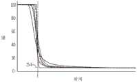
图2是各自具有常规混合器的不同液相色谱系统的流动相的组成的逐步变化的图形描绘。Figure 2 is a graphical depiction of the stepwise change in the composition of the mobile phase of different liquid chromatography systems, each with a conventional mixer.
图3是对于具有不同往复泵的两个系统,液相色谱系统的流动相中的溶剂随时间的存在的图形描绘。Figure 3 is a graphical depiction of the presence of solvent in the mobile phase of a liquid chromatography system over time for two systems with different reciprocating pumps.
图4是可用于在液相色谱系统中混合组成溶剂流的具有流量分布器、混合盘和流量收集器的混合器的示意图。Figure 4 is a schematic diagram of a mixer with flow distributors, mixing discs and flow collectors that can be used to mix constituent solvent streams in a liquid chromatography system.
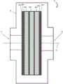
图5A和图5B分别示出了用于液相色谱系统的混合器的实施方案的透视图和剖视示意图。5A and 5B show a perspective view and a schematic cross-sectional view, respectively, of an embodiment of a mixer for a liquid chromatography system.
图6A、图6B和图6C分别是200μm填充床混合器、多路径通道混合器和利用混合盘的混合器的输出响应的图形表示。Figures 6A, 6B, and 6C are graphical representations of the output responses of a 200 μιη packed bed mixer, a multipath channel mixer, and a mixer utilizing a mixing disk, respectively.
图7是九个不同混合器的混合性能作为溶剂流速的函数的图形表示。Figure 7 is a graphical representation of the mixing performance of nine different mixers as a function of solvent flow rate.
图8是图7中的混合器的峰偏度作为溶剂流速的函数的图形表示。8 is a graphical representation of the peak skewness of the mixer in FIG. 7 as a function of solvent flow rate.
图9是针对盘式混合器的四种不同实现方式测量到的噪声的图形表示。Figure 9 is a graphical representation of the noise measured for four different implementations of a disk mixer.
图10A、图10B和图10C分别是可用于在液相色谱系统中混合组成溶剂流的混合器的示例的侧视图、端视图和剖切侧视图。10A, 10B, and 10C are side, end, and cutaway side views, respectively, of examples of mixers that may be used to mix constituent solvent streams in a liquid chromatography system.
图11是图10C所示的环形圈的分解图,示出了固持在环形圈内的部件。FIG. 11 is an exploded view of the annular ring shown in FIG. 10C showing the components retained within the annular ring.
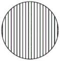
图12是分形流量分布器的示例。Figure 12 is an example of a fractal flow distributor.
图13是分形流量分布器的另一示例。Figure 13 is another example of a fractal flow distributor.
图14示出了混合盘的实施方案的一部分。Figure 14 shows a portion of an embodiment of a mixing disc.
图15A至图15D示出了可在三维制造工艺中使用的光掩模,该三维制造工艺包括聚合物材料的顺序紫外线固化以构建混合盘。Figures 15A-15D illustrate photomasks that may be used in a three-dimensional fabrication process that includes sequential UV curing of polymer materials to build hybrid discs.
图16A和图16B示出了用于混合器的实施方案的流量分布器的表面。16A and 16B show the surface of a flow distributor for an embodiment of a mixer.
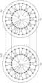
图17描绘了盘式混合器的一个实施方案中的流量分布器的下游表面中的开口相对于流量收集器的上游表面中的开口之间的空间关系。Figure 17 depicts the spatial relationship between the openings in the downstream surface of the flow distributor relative to the openings in the upstream surface of the flow collector in one embodiment of a disk mixer.
图18A和图18B示出了用于混合器的另一实施方案的流量分布器的表面。18A and 18B show the surface of a flow distributor for another embodiment of a mixer.
图19描绘了混合器的另一实施方案中的流量分布器的下游表面中的开口相对于流量收集器的上游表面中的开口之间的空间关系。Figure 19 depicts the spatial relationship between the openings in the downstream surface of the flow distributor relative to the openings in the upstream surface of the flow collector in another embodiment of a mixer.
具体实施方式Detailed ways
本说明书中对“示例”、“实施方案”或“具体实施”的提及意指结合该示例、实施方案或具体实施描述的特定特征、结构或特性包括在本教导的至少一个实施方案中。对本说明书内的特定示例、实施方案或具体实施的提及未必都指代同一实施方案。Reference in this specification to an "example," "embodiment," or "implementation" means that a particular feature, structure, or characteristic described in connection with the example, embodiment, or implementation is included in at least one embodiment of the present teachings. References within this specification to a particular example, implementation, or implementation are not necessarily all referring to the same implementation.
如本文所用,流动相是用于携带样品并穿过液相色谱系统的固定相的溶剂或溶剂的混合物。流动相可为梯度流动相,在该梯度流动相中流动相的组成随时间变化。流动相在本文中也可称为系统流,该系统流通常从流动相的源头流到至少液相色谱系统的检测器。As used herein, a mobile phase is a solvent or mixture of solvents used to carry a sample through the stationary phase of a liquid chromatography system. The mobile phase may be a gradient mobile phase in which the composition of the mobile phase changes over time. The mobile phase may also be referred to herein as a system flow, which typically flows from a source of the mobile phase to at least a detector of a liquid chromatography system.
在简要概述中,描述了具有盘形混合元件的无源混合器。该混合器提高了由液相色谱系统中的往复泵输送的流动相的时间程序化组成的准确度和精确度。该混合器包括流量分布器、混合盘和流量收集器。混合盘具有入口面、出口面和多个通道,每个通道具有在入口面处的入口端和在出口面处的出口端。通道在入口面与出口面之间具有流动方向各向异性。组成溶剂流由流量分布器在混合盘的入口面上分布,并且在穿过混合盘之后在出口面处离开之后被收集,使得混合器的输出是混合的组成溶剂流。In a brief overview, a passive mixer with disk-shaped mixing elements is described. The mixer improves the accuracy and precision of the time-programmed composition of the mobile phase delivered by a reciprocating pump in a liquid chromatography system. The mixer includes a flow distributor, a mixing disc and a flow collector. The mixing disk has an inlet face, an outlet face, and a plurality of channels, each channel having an inlet end at the inlet face and an outlet end at the outlet face. The channel has flow direction anisotropy between the inlet face and the outlet face. The constituent solvent stream is distributed by the flow distributor on the inlet face of the mixing disc and collected after exiting at the outlet face after passing through the mixing disc such that the output of the mixer is a mixed constituent solvent stream.
现在将参考如附图所示的本公开的实施方案来更详细地描述本公开。虽然结合各种实施方案和示例描述了本教导,但是本教导不旨在限制于此类实施方案。相比之下,本公开涵盖各种替代、修改和等同物,如本领域的技术人员将理解。能够访问本文教导的普通技术人员将认识到在本公开的范围内的附加实施方式、修改和实施方案,以及其他使用领域。The present disclosure will now be described in more detail with reference to embodiments of the disclosure as shown in the accompanying drawings. While the present teachings are described in connection with various embodiments and examples, the present teachings are not intended to be limited to such embodiments. In contrast, the present disclosure covers various alternatives, modifications and equivalents, as will be understood by those skilled in the art. A person of ordinary skill with access to the teachings herein will recognize additional implementations, modifications, and implementations within the scope of the disclosure, as well as other areas of use.
图l是可包括下文所述混合器的实施方案的液相色谱系统10的框图。系统10包括与用户界面装置14连通的系统处理器12(例如,微处理器和控制器),该系统处理器用于接收输入参数并向操作者显示系统信息。系统处理器12与为流动相提供一种或多种溶剂的溶剂管理器16通信。例如,溶剂管理器16可包括混合器以混合两种或更多种溶剂,并且可提供梯度流动相。由样品管理器20提供的样品在进样阀24处从色谱柱22上游注射到流动相中。样品管理器20可包括一个或多个样品源,诸如样品贮存器、小瓶或容纳一定体积样品的其他容器。在一些实施方案中,样品管理器20是流通针样品管理器,该流通针样品管理器包括用于从样品源抽吸样品的样品针和样品注射器。在一些情况下,样品管理器20提供包括样品和稀释剂的稀释样品。色谱柱22联接到向系统处理器12提供信号的检测器26。该信号响应于在来自柱22的洗脱液中检测到的各种组分。在行进穿过检测器26之后,系统流离开至废弃物端口;然而,当用于馏分收集时,分流阀可被包括用于将系统流暂时重新引导到一个或多个收集贮器。Figure 1 is a block diagram of a
图2是对于各自具有常规混合器的不同液相色谱系统,流动相中的溶剂B的存在作为时间的函数的图形描绘。横轴表示时间,纵轴表示基于系统检测器的吸收单位。曲线图示出了不同的系统如何响应于水性流动相组合物中溶剂B(丙酮)从100%到10%的程序化逐步降低(在时间t处的竖直虚线34)。在不存在混合器的情况下,可实现急剧的转变;然而,可能存在大的组成噪声。Figure 2 is a graphical depiction of the presence of solvent B in the mobile phase as a function of time for different liquid chromatography systems, each with a conventional mixer. The horizontal axis represents time, and the vertical axis represents absorption units based on system detectors. The graph shows how different systems respond to a programmed stepwise decrease of solvent B (acetone) from 100% to 10% in the aqueous mobile phase composition (dashed
图3是液相色谱系统的流动相中的溶剂随时间的存在的图形描绘。纵轴表示吸收单位并且对应于特定溶剂组分(例如,水性溶剂组合物中的乙腈)的存在。上部曲线图36用于具有20μL泵冲程容积的往复泵,而下部曲线图38用于具有100μL泵冲程容积的往复泵。曲线图36和38中明显的高频噪声是由于往复式泵中的柱塞的操作产生的。Figure 3 is a graphical depiction of the presence of solvent in the mobile phase of a liquid chromatography system over time. The vertical axis represents absorption units and corresponds to the presence of a particular solvent component (eg, acetonitrile in an aqueous solvent composition). The upper graph 36 is for a reciprocating pump with a pump stroke volume of 20 μL, while the
图4是可用于在液相色谱系统中混合组成溶剂流的混合器50的高度示意图。混合器50包括流量分布器52、混合盘54和流量收集器56。Figure 4 is a highly schematic illustration of a
流量分布器具有分布器入口端口58和具有出口横截面的分布器出口端口60。流量分布器52将在分布器入口端口58处接收到的组合溶剂流基本上均匀地在分布器出口端口60处的出口横截面上分布。The flow distributor has a
混合盘54具有入口面62、出口面64,以及具有在入口面62处的入口端和在出口面64处的出口端的通道。在一些实施方案中,混合盘54是圆形盘;然而,替代实施方案可包括具有其他形状(诸如矩形边缘或其他非圆形外边缘)的盘。入口面62与分布器出口端口60连通。通道在入口面62与出口面64之间具有流动方向各向异性。例如,限定在每个通道的入口端与出口端之间的流动路径长度通常可以是不同的,并且在流动路径长度的范围内变化,如下面更详细描述的。每个通道通常在入口面62与出口面64之间不具有直接路径,而是由方向变化限定,使得通道方向沿着其长度变化。例如,每个路径可具有一个或多个向上、向下和/或侧向偏移(即,径向偏移),使得路径基本上是非线性的。在一些实施方案中,通道可允许液体沿着流动路径的部分向后流动,但在这样的实施方案中,压力阻力可能是显著的。通道方向在沿其长度的一部分处包括纵向分量(沿垂直于盘面的“厚度轴”限定)和径向分量(在正交于厚度轴的平面中限定)。因此,溶剂包的各个溶剂组分的宽度在其通过混合盘54的通道中变宽,因为该包被分布到具有通过盘材料的不同流动路径长度的不同通道中,并且由梯度比例阀生成的堆叠的溶剂包可在混合盘容积中有效地混合。溶剂组分由此与相邻的溶剂组分混合,该相邻的溶剂组分也通过穿过混合盘54而变宽。可使用三维(3D)制造工艺(例如,通过立体光刻)来制造混合盘54以实现混合器性质的混合器到混合器的再现性。The
流量收集器56具有收集器入口端口66和收集器出口端口68。收集器入口端口66具有入口横截面并且与混合盘54的出口面64连通,从而接收在穿过混合盘54之后的组成溶剂流的流量。流量收集器56基本上均匀地收集来自混合盘54的出口面64处的通道端部的流体并将其组合成在收集器输出端口68处的单个流。The
在一些实施方案中,流量分布器52的出口横截面的面积基本上等于混合盘54的入口面62的横截面面积。类似地,流量收集器56的入口横截面的面积可基本上等于混合盘54的出口面66的横截面面积。流量分布器52可以是径向流量分布器、角流量分布器、径向流量分布器和角流量分布器的组合,或分形流量分布器。类似地,流量收集器56可以是径向流量收集器、角流量收集器、径向流量收集器和角流量收集器的组合,或分形流量收集器。这些类型的流量分布器52和流量收集器56使得混合盘54的大部分体积能够用于混合。类似地,对于给定的混合器体积,使用用于混合的盘产生最大混合。In some embodiments, the outlet cross-sectional area of
在不存在流动限制的情况下,所接收的溶剂流的有限发散将不会在混合盘54的整个输入面62上扩散。此外,混合器50的性能与混合器体积的平方成比例。因此,流量分布器52用于将在入口端口58处接收到的组成溶剂流均匀地分布成在混合盘54的入口面62处入射的大量(例如,至少十个)各个流。例如,入口端口58处的溶液流的直径可以是大约100μm至200μm,并且每个单个流的直径可以类似地是大约100μm至大约200μm。流量收集器56类似地将从混合盘54的出口面64离开的各个流均匀地收集成直径大约100μm至200μm的单个流。此直径范围可在混合盘54中引起显著的分子色散,并提供大于流量分布器52和流量收集器56的流量限制的流量限制。In the absence of flow restrictions, the limited divergence of the received solvent flow will not spread across the
如本文所用,迂曲度是指通道在其端部之间的流动路径长度与其端部之间的直线距离的归一化的比率。因此,迂曲度是用于流体色散通过混合介质的回旋通道的表征。混合盘54的迂曲度由通道的平均流动路径长度相对于混合盘54的厚度给出。在一些实施方案中,通道的迂曲度至少为五,在其他实施方案中,通道的迂曲度不超过十。混合器50可通过RTD来表征,该RTD由通过混合盘54的不同流动路径长度确定。通过混合盘54的随机通道结构的目的是扩大RTD。混合盘54的流动各向异性和多通道迂曲度使得RTD的偏度能够减小到接近零的值,并且允许在收集器出口端口68处的溶剂混合物的溶剂组合物更快速地实现程序化的溶剂组合物。As used herein, tortuosity refers to the normalized ratio of the flow path length of a channel between its ends to the straight-line distance between its ends. Thus, tortuosity is a characterization of a convoluted channel for fluid dispersion through a mixed medium. The tortuosity of the
在一些实施方案中,根据混合盘54的内部多孔结构随机限定流动路径长度。混合盘54可由具有随机多孔结构的色散材料形成。在此情况下,通道的流动路径长度基本上彼此不相关。In some embodiments, the flow path length is defined randomly according to the internal porous structure of the
混合盘54的空隙体积优选地基于泵系统的泵冲程体积来选择。在一些实施方案中,空隙体积的值在约两倍泵冲程体积至约三倍泵冲程体积之间。例如,基于三倍泵冲程容积,400μm混合器可与具有132μL泵冲程容积的泵系统一起使用。The void volume of the
在一些实施方案中,混合盘54经由机加工工艺或3D打印来制造。混合盘54可包括具有一定范围的路径流动路径长度的预定通道布置或包括通道迷宫。盘材料优选地是化学惰性材料,诸如玻璃、聚合物或金属。在一个优选实现方式中,混合盘54是清洁的钝化不锈钢无序结构,其相对于溶剂是惰性的。In some embodiments, mixing
流量分布器52和流量收集器56的体积优选地比混合盘54的空隙体积小,从而限制混合器50上的总压降。在一个示例中,对于室温下的水,在5mL/min的流速下,混合器50上的压降不超过20MPa(3000psi)。The volume of
图5A和图5B分别示出了用于液相色谱系统的混合器70的示例的透视图和剖视示意图。混合器70由堆叠的金属筛目层形成,其中某些筛目层的组合基本上对应于图4的混合器50的流量收集器52、混合盘54和流量收集器56,以能够评估混合性能。5A and 5B show a perspective view and a schematic cross-sectional view, respectively, of an example of a
混合器70包括壳体72、沿着流动轴76接收溶剂组合物流的入口74和提供混合的溶剂组合物流的出口78。入口74被构造成接收与引导溶剂组合物流的导管(例如,不锈钢管)联接的配件。类似地,出口78被构造成接收与导管联接以引导来自混合器70的混合溶剂组合物流的配件。由于筛目混合器70的对称结构,入口74和出口78的作用可颠倒。
混合器70包括第一对筛目层80A和80B、第二对筛目层82A和82B以及一组三个筛目层84A、84B和84C。在一个实施方案中,两对筛目层80和82用作流量分布器和流量收集器的替代物。每个层80或82是具有5μm筛目间隙间距的75μm厚的不锈钢筛目。每对层80和82用作限流器,以接近理想的流量分布或理想的流量收集。层堆叠中间的三个层84中的每个层是具有40μm筛目间隙间距的400μm厚的不锈钢筛目。层组84形成用作混合盘的多孔色散结构。应当注意,在改进的实现方式中,将使用无序的或随机的材料来代替在径向方向上具有优先扩散的层组84,从而增加迂曲度并且使得能够改进RTD的偏度的减小。The
图6A、图6B和图6C分别示出了200μm填充床混合器、多路径通道混合器和利用混合盘的混合器的输出响应。图中的每个曲线图表示混合器对在不同流速下在混合器入口处接收的溶剂流中的组合物脉冲的响应。每个曲线图相对于x轴的位置不是基于何时观察到响应,而是可被移位以允许更容易地观察各个曲线图;然而,每个曲线图的形状和宽度确实表示每个响应的形状和持续时间。右侧显示的曲线图处于较慢的流速,并且在时间上表现出最大的扩散。流速范围为0.005mL/min至2.0mL/min。Figures 6A, 6B, and 6C show the output responses of a 200 μm packed bed mixer, a multipath channel mixer, and a mixer utilizing a mixing disk, respectively. Each graph in the figure represents the response of the mixer to a composition pulse in the solvent stream received at the mixer inlet at different flow rates. The position of each graph relative to the x-axis is not based on when the response was observed, but can be shifted to allow easier viewing of the individual graphs; however, the shape and width of each graph do represent the shape and duration. The graph shown on the right is at slower flow rates and exhibits maximum dispersion over time. Flow rates range from 0.005mL/min to 2.0mL/min.
图7是九个不同混合器的混合性能(标准化色散)作为溶剂流速的函数的图形表示,并且图8是图7中的混合器的对称性(表示为峰偏度)作为溶剂流速的函数的图形表示。混合性能表示为σ2/V2,其中σ2是方差,V是混合器的混合体积,其中σ2/V2的理想值为一。偏度值被限定为μ3/σ1.5,其中μ3是浓度分布的基于体积的第三中心矩。在评估混合器的性能特征时,应当认识到在色散性能与对称性之间存在折衷。Figure 7 is a graphical representation of the mixing performance (normalized dispersion) of nine different mixers as a function of solvent flow rate, and Figure 8 is a graph of the symmetry (expressed as peak skewness) of the mixers in Figure 7 as a function of solvent flow rate Graphic representation. The mixing performance is expressed as σ2 /V2 , where σ2 is the variance and V is the mixing volume of the mixer, where the ideal value of σ2 /V2 is one. The skewness value is defined as μ3 /σ1.5 , where μ3 is the third volume-based central moment of the concentration distribution. When evaluating the performance characteristics of a mixer, it should be recognized that there is a tradeoff between dispersion performance and symmetry.
尽管填充床混合器的混合性能差一个至两个数量级,但它们的对称性是最好的,因为填充床混合器在所有流速下都具有接近零的偏度值。相比之下,两个多流动路径混合器具有更好的混合性能。然而,它们的峰偏度在较高流速下较差。Although the mixing performance of packed bed mixers is one to two orders of magnitude worse, their symmetry is the best because packed bed mixers have near zero skewness values at all flow rates. In contrast, two multi-flow path mixers have better mixing performance. However, their peak skewness is worse at higher flow rates.
盘式混合器与多流动路径混合器一样具有良好的混合性能,并且比多流动路径混合器具有更好的对称性。尽管5μm和14μm筛目混合器混合良好,但它们表现出“拖尾”,并且因此具有差的对称性,如图8中所示。基于良好的混合和更好的偏度,40μm、95μm和180μm筛目混合器具有最佳的总体性能,不考虑具有较差混合的两个填充床混合器。尽管多流动路径混合器在低流速下的偏度更好,但随着流速增加,它们的对称性迅速变差。筛目混合器明显更独立于流速,特别是40μm、95μm和180μm筛目混合器。不存在混合和对称性都最佳的混合器。该折衷基于选择具有良好混合的混合器(图7),然后基于在所有相关流速下的偏度从该组中识别一个或多个混合器(图8)。在一些情况下,该识别是基于可接受的偏度值,该偏度值也基本上独立于流速。Disk mixers have the same good mixing performance as multi-flow path mixers and have better symmetry than multi-flow path mixers. Although the 5 μm and 14 μm mesh mixers mixed well, they exhibited “tailing” and thus poor symmetry, as shown in FIG. 8 . Based on good mixing and better skewness, the 40 μm, 95 μm and 180 μm mesh mixers had the best overall performance, disregarding the two packed bed mixers with poorer mixing. Although multi-flow path mixers have better skewness at low flow rates, their symmetry rapidly deteriorates as flow rates increase. The mesh mixers are significantly more independent of flow rate, especially the 40 μm, 95 μm and 180 μm mesh mixers. There is no mixer with optimal mixing and symmetry. This compromise is based on selecting a mixer with good mixing (Figure 7) and then identifying one or more mixers from this group based on skewness at all relevant flow rates (Figure 8). In some cases, this identification is based on acceptable skewness values, which are also substantially independent of flow rate.
基于使用40μm和100μm介质级不锈钢制成的盘式混合器进行盘式混合机性能的评估。图9示出了测量数据的图形表示。将每个数据点绘制为根据x轴以微升为单位的混合器体积和根据y轴以微吸收单位为单位的噪声的函数。每个数据点的噪声值被确定为六十个测量窗口的最大峰间噪声的平均值,其中每个窗口具有十秒的持续时间。四个曲线图对应于具有40μm混合器盘介质的盘式混合器、具有40μm盘式混合器介质与附加分流混合器组合的盘式混合器、具有100μm盘式混合器介质的盘式混合器,以及具有100μm盘式混合器介质与附加分流混合器组合的盘式混合器。盘式混合器介质购自Farmington,CT的MottCorporation。测量结果显示,即使对于较低的混合器体积,也不再能够观察到周期性泵噪声,在测量窗口中只有随机的峰间噪声对测量到的噪声值有贡献。在较高的混合器体积下,绘制的噪声值不显著大于紫外(UV)检测器的背景噪声。The evaluation of pan mixer performance was based on the use of pan mixers made of 40 μm and 100 μm media grade stainless steel. Figure 9 shows a graphical representation of the measurement data. Each data point is plotted as a function of mixer volume in microliters according to the x-axis and noise in microabsorption units according to the y-axis. The noise value for each data point was determined as the average of the maximum peak-to-peak noise for sixty measurement windows, where each window had a duration of ten seconds. The four graphs correspond to a disk mixer with a 40 μm mixer disk medium, a disk mixer with a 40 μm disk mixer medium combined with an additional split mixer, a disk mixer with a 100 μm disk mixer medium, And a disk mixer with 100 μm disk mixer media combined with an additional split mixer. Pan mixer media was purchased from Mott Corporation of Farmington, CT. The measurements show that even for lower mixer volumes the periodic pump noise is no longer observable and only random peak-to-peak noise in the measurement window contributes to the measured noise value. At higher mixer volumes, the plotted noise values are not significantly larger than the background noise of the ultraviolet (UV) detector.
图10A、图10B和图10C分别是可用于在液相色谱系统中混合组成溶剂流的混合器100的示例的侧视图、端视图和剖切侧视图。该混合器包括第一壳体部件102、第二壳体部件104、环形圈106、流量分布器108、混合盘110和流量收集器112。流量分布器108、混合盘110和流量收集器112固持在环形圈106内。第一壳体部件102包括在外表面上的螺纹,该螺纹接合第二壳体部件104的内孔表面上的螺纹。第一壳体部件102插入到第二壳体部件104中,直到两个部件都与环形圈106的相对侧接触。一对垫圈114A和114B分别在环形圈106与第一壳体部件102之间以及环形圈106与第二壳体部件104之间形成流体密封。在混合器端口116A处进入混合器100的液体在混合器端口116B处离开。混合器100可替代地与沿相反方向(即,通过在混合器端口116B处进入并且在混合器端口116A处离开)流动的液体一起使用。10A, 10B, and 10C are side, end, and cutaway side views, respectively, of an example of a
图11是环形圈106和固持在圈106内的部件的分解图。流量分布器108包括入口角色散板118和入口径向色散板120。混合盘110包括具有随机多孔结构的盘122,该盘设置在两个细筛目盘124A和124B(例如,各自具有5μm间距的两个金属筛目筛)之间。流量收集器112包括出口径向色散板126和出口角色散板128。FIG. 11 is an exploded view of the
入口角色散板118和出口角色散板128分别包括中心开口130和131,槽132从中心开口130和131径向延伸。槽132是楔形的,即,宽度随着距中心的距离增加而增加。入口径向色散板120和出口径向色散板126分别包括布置在距板中心三个不同半径中的一者处的同心弧形槽134的布置。槽的宽度随着距中心的距离增加而变大。角色散板和径向色散板的组合用于有效地分布或收集流入或流出混合盘110的独立流。应当理解,板118和128的材料和尺寸以及板中的槽132和134的布置(包括数量和尺寸)在其他实施方案中可以不同。The inlet
图12是可例如使用3D打印立体光刻工艺制造的分形流量分布器140的示例。分布器140包括被分成两个分支通道的中心通孔,每个分支通道又被分成两个分支通道,每个分支通道被进一步分成另外两个分支通道等等。通道的分裂穿过分布器板或盘的厚度发生以在表面上生成流的分形分布。图13是可使用类似制造工艺制造的分形流量分布器150的另一示例。在此示例中,分布器150包括被分成三个分支通道的结构,每个分支通道被分裂并通向三个分支通道,每个分支通道通向另外三个分支通道。FIG. 12 is an example of a
图14是混合盘160的一部分的示例,该混合盘可使用诸如立体光刻的3D制造工艺用聚合物材料制成。例如,图15A和图15D中所示的光掩模的使用可交替地用于聚合物材料的顺序UV固化,以在一侧上构建50μm的正方形特征部。首先,使用图15A中所示的光掩模形成直通道,然后使用图15D中所示的光掩模形成正方形横截面通道。所得切片的厚度取决于UV光源的强度、聚合物材料中光引发剂化合物的浓度、单体浓度和UV曝光时间。固化过程可重复多次,在固化循环之间去除未聚合的材料。以此方式,可堆叠许多层以通过相对于其他切片平移和/或旋转(例如,参见图15B和图15C中的光掩模)每个切片来制造各种3D结构。此工艺仅仅是用于形成混合盘的制造技术的一个示例,并且应当理解也可使用其他制造技术。FIG. 14 is an example of a portion of a hybrid disk 160 that may be fabricated from a polymer material using a 3D manufacturing process such as stereolithography. For example, the use of photomasks shown in Figures 15A and 15D can be alternately used for sequential UV curing of polymer materials to build 50 μm square features on one side. First, straight channels were formed using the photomask shown in Figure 15A, and then square cross-sectional channels were formed using the photomask shown in Figure 15D. The thickness of the resulting slices depends on the intensity of the UV light source, the concentration of the photoinitiator compound in the polymer material, the monomer concentration and the UV exposure time. The curing process can be repeated multiple times, with unpolymerized material removed between cure cycles. In this way, many layers can be stacked to fabricate various 3D structures by translating and/or rotating each slice relative to other slices (eg, see the photomask in Figures 15B and 15C). This process is only one example of a fabrication technique for forming a hybrid disc, and it should be understood that other fabrication techniques may also be used.
在上述各种实施方案中,流量分布器和流量收集器被类似地构造。例如,流量分布器从分布器入口到分布器出口的结构可与流量收集器从收集器出口到收集器入口的结构相同。In the various embodiments described above, the flow distributors and flow collectors are similarly constructed. For example, the configuration of the flow distributor from the distributor inlet to the distributor outlet can be the same as the configuration of the flow collector from the collector outlet to the collector inlet.
在一个实施方案中,流量分布器由具有第一(上游)表面160A和第二(下游)表面160B的单个盘形板160制成,分别如图16A和图16B所示。第一表面160A示出了分形分布路径结构。一系列流体路径从接收来自分布器入口的流的开放的圆形中心区域162开始。第一流动路径164A在一端处从中心区域162径向延伸到垂直于第一流动路径164A的第二流动路径164B的中点处的相对端。第二流动路径164B的每个端靠近或位于第三流动路径164C的中点处。如图所示,存在12个第一流动路径164A、12个第二流动路径164B和24个第三流动路径164C。在第三流动路径164C中的每个第三流动路径的每个端处是在下游表面160B处的开口166。In one embodiment, the flow distributor is made from a single disk-shaped plate 160 having a first (upstream)
流量分布器的流体路径和其他特征部可以多种方式形成。例如,可利用已知的微机械加工技术。或者,可利用蚀刻工艺来形成所要结构。The fluid paths and other features of the flow distributor can be formed in a variety of ways. For example, known micromachining techniques can be utilized. Alternatively, an etching process can be utilized to form the desired structure.
每个开口166沿着半径为R1或R2的两个同心圆中的一个同心圆限定,每个圆与混合器流动轴同心。因此,在分布器入口端口处接收到的流在内部被分成12个流,每个流被分成四个流,使得离开第二表面160B的流的数量是48。开口166的直径优选地相等。在非限制性数值示例中,由所有48个开口限定的总面积为第二表面160B的总表面积的大约百分之五。Each
在一个实施方案(实施方案A)中,流量分布器和流量收集器具有相同的构造,即,混合器表现出关于混合盘的轴向镜像对称。换句话说,流量分布器的第一表面160A与流量收集器的第二表面相同,流量分布器的第二表面160B与流量收集器的第一表面相同。因此,混合器被构造成使得流量收集器的特征部被布置在与流量分布器的特征部相反的轴向流动方向上,但是在其他方面是相同的。图17示出了在以此方式构造的混合器中流量分布器的第二(下游)板160B中的开口166相对于流量收集器的第一(上游)表面170A中的开口176之间的关系。每个开口166和176位于半径为R1和R2的两个同心圆中的一个同心圆上。分布器出口端口处的开口与收集器入口端口处的开口相同地布置。因此,在流量分布器的第二表面160B中的每个开口166与流量收集器的第一表面170A中的相应开口176之间存在一对一的对应关系。然而,在其他实施方案中,流量分布器和流量收集器不限定围绕混合盘的对称布置,如下文进一步描述。In one embodiment (embodiment A), the flow distributor and the flow collector have the same configuration, ie the mixer exhibits axial mirror symmetry about the mixing disc. In other words, the
图18A和图18B分别描绘了在流量分布器的不同实现方式中使用的上游表面180A和下游表面180B。第一表面180A示出了一系列流体路径,该流体路径从接收来自分布器入口的流的开放的圆形中心区域182开始。第一流动路径184A在一端从中心区域182径向延伸到在垂直于第一流动路径184A布置的短的第二流动路径184B的中点处的相对端。每个第二流动路径184B的每个端与三个第三流动路径184C中的每个第三流动路径的一个端联接。如图所示,存在12个第一流动路径184A、12个第二流动路径184B和36个第三流动路径184C。在第三流动路径184C中的每个第三流动路径的每个端处是在下游表面180B处的开口186。18A and 18B depict an
每个开口186沿着半径为R1’、R2’、R3’和R4’的四个同心圆中的一个同心圆限定,所有同心圆与混合器流动轴同心。在分布器入口端口处接收到的流被分成12个流,每个流被分成两个流,每个流被进一步分成三个流,使得离开第二表面180B的流的数量是72。因此,入射在混合盘的上游表面上的各个流的数量大于图16A和图16B所示的实施方案的各个流的数量。Each
在混合器的一个实施方案(实施方案B)中,流量分布器和流量收集器都形成为相同的部件,每个部件具有72个开口,并且围绕混合盘对称地布置。In one embodiment of the mixer (embodiment B), both the flow distributor and the flow collector are formed as identical parts, each having 72 openings, arranged symmetrically around the mixing disc.
在另一实施方案(实施方案C)中,使用如图16A和图16B中所示的流量分布器以及如图18A和图18B中所示的流量收集器来构造混合器。因此,流量分布器包括与混合盘的上游侧相邻的48个开口166,而流量收集器包括在混合盘的下游侧的72个开口186。图19示出了在以此方式构造的混合器中流量分布器的第二表面160B中的开口166相对于流量收集器的第一(上游)表面180A中的开口176之间的关系。可看出,其上限定了开口166的半径为R1和R2的同心圆不同于其上限定了开口176的半径为R1’、R2’、R3’和R4’的同心圆。In another embodiment (Embodiment C), a mixer is constructed using a flow distributor as shown in Figures 16A and 16B and a flow collector as shown in Figures 18A and 18B. Thus, the flow distributor includes 48
在又一实施方案(实施方案D)中,使用如图18A和图18B所示的流量分布器以及根据图16A和图16B所示的结构形成的流量收集器来构造混合器。在此布置中,流量分布器包括与混合盘的上游侧相邻的72个开口186,并且流量收集器包括在混合盘的下游侧的48个开口166。与实施方案C一样,开口166和176的同心圆是不同的。In yet another embodiment (embodiment D), a mixer is constructed using a flow distributor as shown in Figures 18A and 18B and a flow collector formed according to the structure shown in Figures 16A and 16B. In this arrangement, the flow distributor includes 72
使用分析物的脉冲输入确定根据实施方案A到D的混合器的停留时间分布来进行性能评估。测量结果显示,相对于实施方案A,实施方案B在其停留时间分布中具有较高的峰和略微较窄的宽度。实施方案C和D具有几乎相同的停留时间分布,其峰高度类似于实施方案B的峰高度;然而,实施方案C和D具有更好对称性的停留时间分布。The performance evaluation was performed using the pulsed input of the analyte to determine the residence time distribution of the mixers according to embodiments A to D. The measurements show that, relative to Embodiment A, Embodiment B has higher peaks and slightly narrower widths in its residence time distribution. Embodiments C and D have nearly identical residence time distributions with peak heights similar to those of Embodiment B; however, Embodiments C and D have more symmetrical residence time distributions.
应当认识到,内部流动路径和/或开口的数量可与上述那些不同。例如,可使用分形阶数大于二的任何分流分支。例如,可堆叠两个或更多个分流盘元件。类似地,内部流动路径和开口的布置可以不同。例如,开口可布置在不同数量的同心圆上。可考虑开口的其他布置。It should be appreciated that the number of internal flow paths and/or openings may vary from those described above. For example, any branching branch with a fractal order greater than two can be used. For example, two or more diverter tray elements may be stacked. Similarly, the arrangement of internal flow paths and openings can vary. For example, the openings may be arranged on a different number of concentric circles. Other arrangements of openings are contemplated.
虽然已经参考特定实施方案示出和描述了本技术,但是本领域的技术人员应理解,在不脱离权利要求的范围的情况下,可在形式和细节上进行各种改变。While the technology has been shown and described with reference to particular embodiments, it will be understood by those skilled in the art that various changes in form and details may be made without departing from the scope of the claims.
Claims (23)
Applications Claiming Priority (3)
| Application Number | Priority Date | Filing Date | Title |
|---|---|---|---|
| US202063048684P | 2020-07-07 | 2020-07-07 | |
| US63/048684 | 2020-07-07 | ||
| PCT/US2021/039058WO2022010665A1 (en) | 2020-07-07 | 2021-06-25 | Mixer for liquid chromatography |
Publications (1)
| Publication Number | Publication Date |
|---|---|
| CN116134312Atrue CN116134312A (en) | 2023-05-16 |
Family
ID=77022244
Family Applications (1)
| Application Number | Title | Priority Date | Filing Date |
|---|---|---|---|
| CN202180048542.4APendingCN116134312A (en) | 2020-07-07 | 2021-06-25 | Mixer for liquid chromatography |
Country Status (4)
| Country | Link |
|---|---|
| US (1) | US11898999B2 (en) |
| EP (1) | EP4179310B1 (en) |
| CN (1) | CN116134312A (en) |
| WO (1) | WO2022010665A1 (en) |
Citations (6)
| Publication number | Priority date | Publication date | Assignee | Title |
|---|---|---|---|---|
| JP2011107004A (en)* | 2009-11-19 | 2011-06-02 | Senshu Scientific Co Ltd | Mobile phase mixing apparatus for high performance liquid chromatograph and control method of the apparatus |
| US20160266078A1 (en)* | 2014-01-09 | 2016-09-15 | Hitachi High-Technologies Corporation | Liquid Mixing Device, and Liquid Chromatography Apparatus |
| CN109959745A (en)* | 2017-12-22 | 2019-07-02 | 苏州普源精电科技有限公司 | A mixer and liquid chromatograph |
| CN209342666U (en)* | 2018-11-29 | 2019-09-03 | 江苏永安化工有限公司 | A kind of mobile phase mixer and chromatographic analyzer of liquid phase |
| US20190337211A1 (en)* | 2018-05-03 | 2019-11-07 | University Of Massachusetts | Distributive and dispersive mixing devices |
| CN111050895A (en)* | 2017-09-06 | 2020-04-21 | 沃特世科技公司 | Fluid mixer |
Family Cites Families (176)
| Publication number | Priority date | Publication date | Assignee | Title |
|---|---|---|---|---|
| US3595531A (en) | 1969-11-04 | 1971-07-27 | Dow Chemical Co | Mixer apparatus |
| US3830369A (en) | 1973-12-11 | 1974-08-20 | E Pfadenhauer | High pressure gradient chamber for liquid chromatography |
| US4437812A (en) | 1977-05-13 | 1984-03-20 | Varian Associates, Inc. | Single-pump multiple stroke proportioning for gradient elution liquid chromatography |
| US4311586A (en) | 1980-04-22 | 1982-01-19 | Tracor, Inc. | Solvent mixing in HPLC using low pressure solvent metering pumps |
| DE3037898A1 (en) | 1980-10-07 | 1982-05-06 | Bruker Analytische Meßtechnik GmbH, 7512 Rheinstetten | MIXING CHAMBER |
| US4506987A (en) | 1982-09-08 | 1985-03-26 | The United States Of America As Represented By The United States Department Of Energy | High pressure liquid chromatographic gradient mixer |
| JPS5994064A (en) | 1982-11-19 | 1984-05-30 | Shimadzu Corp | Gradient mixer |
| US4496245A (en) | 1983-03-07 | 1985-01-29 | International Business Machines Corporation | Liquid chromatography proportioning valve and mixer |
| US4534659A (en) | 1984-01-27 | 1985-08-13 | Millipore Corporation | Passive fluid mixing system |
| JPS62210042A (en) | 1986-03-07 | 1987-09-16 | Hitachi Ltd | Device for mixing liquid |
| US4882062A (en) | 1986-08-29 | 1989-11-21 | Rainin Instrument Co., Inc. | Solvent mixing chamber for a liquid chromatography system |
| GB2195265B (en) | 1986-09-17 | 1990-06-20 | Philips Electronic Associated | Liquid chromatograph apparatus |
| US4954253A (en) | 1987-05-14 | 1990-09-04 | Nauchno-Tekhnicheskoe Objedinenie Akademii Nauk Sssr | Device for preparing a gradient solution for a high-pressure liquid chromatograph |
| US4882063A (en) | 1987-07-13 | 1989-11-21 | Isco, Inc. | Chromatographic system |
| JPH02167469A (en) | 1988-12-21 | 1990-06-27 | Yokogawa Electric Corp | Solvent mixer for liquid chromatography |
| JPH02170047A (en) | 1988-12-23 | 1990-06-29 | Yokogawa Electric Corp | Solvent mixer for liquid chromatography |
| JP2587162Y2 (en) | 1991-11-15 | 1998-12-14 | ジーエルサイエンス株式会社 | Liquid chromatograph mixer |
| US5664938A (en) | 1992-03-05 | 1997-09-09 | Yang; Frank Jiann-Fu | Mixing apparatus for microflow gradient pumping |
| US5275723A (en) | 1992-07-06 | 1994-01-04 | Sp Industries Ltd. Partnership | Mobile phase reservoir |
| EP0583003A1 (en) | 1992-08-13 | 1994-02-16 | Perseptive Biosystems, Inc. | Fluid metering, mixing and composition control system |
| JPH06324026A (en) | 1993-05-11 | 1994-11-25 | Irika Kiki Kk | Liquid chromatrography device |
| JP2603770Y2 (en) | 1993-06-30 | 2000-03-21 | ジーエルサイエンス株式会社 | Gradient mixer for liquid chromatography |
| FR2708480B1 (en) | 1993-08-02 | 1996-05-24 | Inst Francais Du Petrole | Single-phase fluid distributor-mixer-extractor for granular solids beds. |
| JPH07159388A (en) | 1993-12-02 | 1995-06-23 | Jeol Ltd | Mixer for supercritical fluid chromatography |
| EP0686848A1 (en) | 1994-05-09 | 1995-12-13 | Shiseido Company Limited | Liquid chromatograph having a micro and semi-micro column |
| JP3560652B2 (en) | 1994-09-06 | 2004-09-02 | コニカミノルタホールディングス株式会社 | Mixing method |
| DE19511603A1 (en) | 1995-03-30 | 1996-10-02 | Norbert Dr Ing Schwesinger | Device for mixing small amounts of liquid |
| US5656034A (en) | 1995-03-31 | 1997-08-12 | Perkin Elmer Corp | High-pressure micro-volume syringe pump |
| TW293783B (en) | 1995-06-16 | 1996-12-21 | Ciba Geigy Ag | |
| DE19536856C2 (en) | 1995-10-03 | 1997-08-21 | Danfoss As | Micromixer and mixing process |
| US20010055812A1 (en) | 1995-12-05 | 2001-12-27 | Alec Mian | Devices and method for using centripetal acceleration to drive fluid movement in a microfluidics system with on-board informatics |
| JP3665680B2 (en) | 1996-06-05 | 2005-06-29 | ジーエルサイエンス株式会社 | Trace analysis method and liquid chromatograph |
| JP3534944B2 (en) | 1996-06-05 | 2004-06-07 | ジーエルサイエンス株式会社 | Liquid chromatograph mixer |
| FR2768189B1 (en) | 1997-09-05 | 2004-10-15 | Inst Francais Du Petrole | PUMPING METHOD AND SYSTEM FOR MIXING LIQUIDS |
| US5887977A (en) | 1997-09-30 | 1999-03-30 | Uniflows Co., Ltd. | Stationary in-line mixer |
| DE19813600A1 (en) | 1998-03-27 | 1999-09-30 | Bayer Ag | Static disc mixer |
| AU3975399A (en) | 1998-05-07 | 1999-11-23 | Purdue Research Foundation | An (in situ) micromachined mixer for microfluidic analytical systems |
| BR9914554A (en) | 1998-10-13 | 2001-06-26 | Biomicro Systems Inc | Fluid circuit components based on passive fluid dynamics |
| US6637463B1 (en) | 1998-10-13 | 2003-10-28 | Biomicro Systems, Inc. | Multi-channel microfluidic system design with balanced fluid flow distribution |
| DE19902697A1 (en) | 1999-01-14 | 2000-07-20 | Guenter J Eppert | Dynamic mixing chamber for high pressure liquid chromatography process has minimum dwell volume and exactly reproduces liquid gradients |
| US7241423B2 (en) | 2000-02-03 | 2007-07-10 | Cellular Process Chemistry, Inc. | Enhancing fluid flow in a stacked plate microreactor |
| JP4348820B2 (en) | 2000-03-24 | 2009-10-21 | 株式会社島津製作所 | Liquid mixer |
| US6893547B2 (en) | 2000-06-14 | 2005-05-17 | Board Of Regents, The University Of Texas System | Apparatus and method for fluid injection |
| DE60008516T2 (en) | 2000-07-20 | 2004-12-23 | Agilent Technologies Inc., A Delaware Corp., Palo Alto | Method and device for mixing fluids |
| JP2004508550A (en) | 2000-09-08 | 2004-03-18 | ダウ グローバル テクノロジーズ インコーポレーテッド | Sequential detection ion chromatography |
| US6705357B2 (en) | 2000-09-18 | 2004-03-16 | President And Fellows Of Harvard College | Method and apparatus for gradient generation |
| US7105304B1 (en) | 2000-11-07 | 2006-09-12 | Caliper Life Sciences, Inc. | Pressure-based mobility shift assays |
| AU2002230524A1 (en) | 2000-11-16 | 2002-05-27 | California Institute Of Technology | Apparatus and methods for conducting assays and high throughput screening |
| CA2441206A1 (en) | 2001-03-19 | 2002-09-26 | Gyros Ab | Characterization of reaction variables |
| CN1259125C (en) | 2001-04-12 | 2006-06-14 | 大赛璐化学工业株式会社 | Filler for separating optical isomers, method for producing same, and method for using same |
| KR100442680B1 (en) | 2001-05-10 | 2004-08-02 | 주식회사 디지탈바이오테크놀러지 | Apparatus for mixing fluids by micro channel |
| US6919046B2 (en) | 2001-06-07 | 2005-07-19 | Nanostream, Inc. | Microfluidic analytical devices and methods |
| US6981522B2 (en) | 2001-06-07 | 2006-01-03 | Nanostream, Inc. | Microfluidic devices with distributing inputs |
| JP4792664B2 (en) | 2001-06-15 | 2011-10-12 | コニカミノルタホールディングス株式会社 | Mixing method, mixing mechanism, micromixer and microchip having the mixing mechanism |
| JP3865119B2 (en) | 2001-06-29 | 2007-01-10 | 株式会社島津製作所 | Mobile phase gradient apparatus and high-performance liquid chromatograph using the same |
| WO2003015890A1 (en) | 2001-08-20 | 2003-02-27 | President And Fellows Of Harvard College | Fluidic arrays and method of using |
| EP1427530B1 (en) | 2001-09-17 | 2010-08-11 | Gyros Patent Ab | Functional unit enabling controlled flow in a microfluidic device |
| US6887384B1 (en) | 2001-09-21 | 2005-05-03 | The Regents Of The University Of California | Monolithic microfluidic concentrators and mixers |
| ATE271919T1 (en) | 2001-10-18 | 2004-08-15 | Aida Eng Ltd | MICRO DOSING AND SAMPLING DEVICE AND MICROCHIP WITH THIS DEVICE |
| JP3780917B2 (en) | 2001-11-22 | 2006-05-31 | 株式会社島津製作所 | Liquid chromatograph and its eluent mixing device |
| US20030123322A1 (en) | 2001-12-31 | 2003-07-03 | Industrial Technology Research Institute | Microfluidic mixer apparatus and microfluidic reactor apparatus for microfluidic processing |
| US20040109793A1 (en) | 2002-02-07 | 2004-06-10 | Mcneely Michael R | Three-dimensional microfluidics incorporating passive fluid control structures |
| FR2836185B1 (en) | 2002-02-21 | 2004-10-15 | Inst Francais Du Petrole | METHOD AND SYSTEM FOR THE FINE DOSING OF INJECTED FLUIDS IN A PUMP INSATLLATION |
| WO2003072255A1 (en) | 2002-02-23 | 2003-09-04 | Nanostream, Inc. | Microfluidic multi-splitter |
| US6958119B2 (en) | 2002-02-26 | 2005-10-25 | Agilent Technologies, Inc. | Mobile phase gradient generation microfluidic device |
| US7901939B2 (en) | 2002-05-09 | 2011-03-08 | University Of Chicago | Method for performing crystallization and reactions in pressure-driven fluid plugs |
| US7976779B2 (en) | 2002-06-26 | 2011-07-12 | California Institute Of Technology | Integrated LC-ESI on a chip |
| WO2004008142A1 (en) | 2002-07-12 | 2004-01-22 | Mitsubishi Chemical Corporation | Analytical chip, analytical chip unit, analyzing apparatus, method of analysis using the apparatus, and method of producing the analytical chip |
| JP3824160B2 (en) | 2002-08-28 | 2006-09-20 | 株式会社島津製作所 | High-speed liquid chromatograph mixer |
| EP1403209A1 (en) | 2002-09-24 | 2004-03-31 | The Technology Partnership Limited | Fluid routing device |
| US20040092033A1 (en) | 2002-10-18 | 2004-05-13 | Nanostream, Inc. | Systems and methods for preparing microfluidic devices for operation |
| US6987263B2 (en) | 2002-12-13 | 2006-01-17 | Nanostream, Inc. | High throughput systems and methods for parallel sample analysis |
| US7178386B1 (en) | 2003-04-10 | 2007-02-20 | Nanostream, Inc. | Parallel fluid processing systems and methods |
| US6916113B2 (en) | 2003-05-16 | 2005-07-12 | Agilent Technologies, Inc. | Devices and methods for fluid mixing |
| US7112277B2 (en) | 2003-06-30 | 2006-09-26 | Agilent Technologis, Inc. | Methods and systems for separating constituents of a highly aqueous fluid |
| JP4082309B2 (en) | 2003-08-22 | 2008-04-30 | 株式会社島津製作所 | Solution mixer for liquid chromatography |
| JP3959436B2 (en) | 2003-08-29 | 2007-08-15 | 独立行政法人物質・材料研究機構 | Flow fluctuation structure and micromixer |
| US7147364B2 (en) | 2003-09-29 | 2006-12-12 | Hitachi High-Technologies Corporation | Mixer and liquid analyzer provided with same |
| US7111501B2 (en) | 2003-10-03 | 2006-09-26 | Agilent Technologies, Inc. | Devices and methods for separating constituents |
| EP1525916A1 (en) | 2003-10-23 | 2005-04-27 | F. Hoffmann-La Roche Ag | Flow triggering device |
| AU2003298273A1 (en) | 2003-11-05 | 2005-06-08 | Agilent Technologies, Inc. | Chromatography system |
| US20070148048A1 (en) | 2003-12-16 | 2007-06-28 | Jousse Fabien Frederic R M | Microfluidic device |
| JP4360206B2 (en) | 2004-01-08 | 2009-11-11 | 東ソー株式会社 | Liquid chromatograph mixer |
| DE102004007567A1 (en) | 2004-02-17 | 2005-09-01 | Boehringer Ingelheim Microparts Gmbh | Microstructured platform and method for handling a liquid |
| US20050252840A1 (en) | 2004-05-13 | 2005-11-17 | Eksigent Technologies, Llc | Micromixer |
| JP2006003203A (en) | 2004-06-17 | 2006-01-05 | Shiseido Co Ltd | Gradient mixer for liquid chromatography |
| US20090294344A1 (en) | 2004-07-13 | 2009-12-03 | Waters Investments Limited | Fluid mixer assembly |
| JP2007523355A (en) | 2004-08-21 | 2007-08-16 | エルジー・ライフ・サイエンシズ・リミテッド | Microfluidic device and diagnostic and analytical apparatus including the same |
| JP2006122735A (en) | 2004-10-26 | 2006-05-18 | Dainippon Screen Mfg Co Ltd | Channel structure and fluid mixing apparatus |
| EP1679115A1 (en) | 2005-01-07 | 2006-07-12 | Corning Incorporated | High performance microreactor |
| WO2006092172A1 (en) | 2005-03-02 | 2006-09-08 | Agilent Technologies, Inc. | Column with additional fluid introduction |
| US20060280029A1 (en) | 2005-06-13 | 2006-12-14 | President And Fellows Of Harvard College | Microfluidic mixer |
| US20060285433A1 (en) | 2005-06-20 | 2006-12-21 | Jing-Tang Yang | Fluidic mixer of serpentine channel incorporated with staggered sudden-expansion and convergent cross sections |
| US20090139576A1 (en) | 2005-08-11 | 2009-06-04 | Eksigent Technologies, Llc | Microfluidic systems, devices and methods for reducing noise generated by mechanical instabilities |
| US20090268548A1 (en) | 2005-08-11 | 2009-10-29 | Eksigent Technologies, Llc | Microfluidic systems, devices and methods for reducing diffusion and compliance effects at a fluid mixing region |
| US20090142846A1 (en) | 2005-08-11 | 2009-06-04 | Eksigent Technologies, Llc | Methods for measuring biochemical reactions |
| WO2007041464A1 (en) | 2005-10-03 | 2007-04-12 | Honeywell International Inc. | Apparatus and method for preparing ultrapure solvent blends |
| US20070113907A1 (en) | 2005-11-18 | 2007-05-24 | Reid Brennen | Devices and methods using fluid-transporting features of differing dwell times |
| US20070246106A1 (en) | 2006-04-25 | 2007-10-25 | Velocys Inc. | Flow Distribution Channels To Control Flow in Process Channels |
| US7744762B2 (en) | 2006-08-24 | 2010-06-29 | Virginia Tech Intellectual Properties, Inc. | Microfluidic devices and methods facilitating high-throughput, on-chip detection and separation techniques |
| WO2008028974A1 (en) | 2006-09-08 | 2008-03-13 | Novo Nordisk A/S | Methods of optimizing chromatographic separation of polypeptides |
| US10254229B2 (en) | 2007-04-18 | 2019-04-09 | Ondavia, Inc. | Portable water quality instrument |
| WO2009009021A1 (en) | 2007-07-06 | 2009-01-15 | The Regents Of The University Of California | Integrated microfluidics for highly parallel screening of chemical reactions |
| US8641267B2 (en) | 2008-04-14 | 2014-02-04 | Agilent Technologies, Inc. | Fluidic conduit with repeated disturbance of laminar flow |
| JP4683066B2 (en) | 2008-04-14 | 2011-05-11 | コニカミノルタホールディングス株式会社 | Liquid mixing mechanism |
| WO2010009247A2 (en) | 2008-07-18 | 2010-01-21 | 3M Innovative Properties Company | Y-cross mixers and fluid systems including the same |
| DE102008037008B3 (en) | 2008-08-08 | 2010-04-08 | Dionex Softron Gmbh | Mixing device for liquid chromatography |
| US8517597B2 (en) | 2008-09-12 | 2013-08-27 | Waters Technologies Corporation | Valve switch modulation for reducing errors due oscillations of the inlet fluid of a pump system |
| JP2009018311A (en) | 2008-10-30 | 2009-01-29 | Hitachi Plant Technologies Ltd | Microfluidic chip |
| KR100941069B1 (en) | 2008-12-22 | 2010-02-09 | 한국전자통신연구원 | Microfluidic dilution device |
| WO2010083884A1 (en) | 2009-01-22 | 2010-07-29 | Agilent Technologies, Inc. | Apparatus for generating small flow rates in a channel |
| WO2010083891A1 (en) | 2009-01-26 | 2010-07-29 | Agilent Technologies, Inc. | Separation device with moveable filling channel |
| US7988859B2 (en) | 2009-02-05 | 2011-08-02 | Chromatan Inc. | Countercurrent tangential chromatography methods, systems, and apparatus |
| EP2403633B1 (en) | 2009-03-06 | 2013-04-17 | Ehrfeld Mikrotechnik BTS GmbH | Coaxial compact static mixer and use thereof |
| DE102009032394B4 (en) | 2009-07-08 | 2013-05-02 | Dionex Softron Gmbh | A method of longitudinal mixing of a liquid comprising at least two liquid components for high performance liquid chromatography |
| US9527010B2 (en) | 2009-09-25 | 2016-12-27 | Ge Healthcare Bio-Sciences Corp. | Separation system and method |
| IN2012DN01945A (en) | 2009-09-25 | 2015-08-21 | Ge Healthcare Bio Sciences Ab | |
| GB2475300B (en) | 2009-11-13 | 2012-12-05 | Alan Finlay | Microengineered supercritical fluid chromatography system |
| WO2011085353A1 (en) | 2010-01-11 | 2011-07-14 | Waters Technologies Corporation | Manifold for solvent mixing in liquid chromatography systems |
| US8511889B2 (en) | 2010-02-08 | 2013-08-20 | Agilent Technologies, Inc. | Flow distribution mixer |
| CN105116080B (en) | 2010-06-16 | 2018-01-09 | 株式会社日立高新技术 | Apparatus for combining liquids and liquid chromatograph |
| EP2663392B1 (en) | 2011-01-12 | 2018-10-03 | Tetra Laval Holdings & Finance SA | Layer multiplier for fluids with high viscosity |
| US20140230528A1 (en) | 2011-06-17 | 2014-08-21 | Waters Technologies Corporation | Turbulent flow mixing device for use in a chromatography system |
| EP2737379B1 (en) | 2011-07-27 | 2018-12-19 | Agilent Technologies, Inc. | Packet-wise proportioning followed by immediate longitudinal mixing |
| US10238989B2 (en) | 2011-12-14 | 2019-03-26 | Waters Technologies Corporation | Hybrid gradient delivery system and operation |
| JP6162716B2 (en) | 2011-12-14 | 2017-07-12 | ウオーターズ・テクノロジーズ・コーポレイシヨン | Target frequency multipath length mixer |
| WO2013116285A1 (en) | 2012-02-01 | 2013-08-08 | Waters Technologies Corporation | Managing fluidic connections to microfluidic devices |
| GB2524608B (en) | 2012-04-25 | 2020-04-15 | Agilent Technologies Inc | Prevention of phase separation upon proportioning and mixing fluids |
| GB2519686A (en) | 2012-06-15 | 2015-04-29 | Agilent Technologies Inc | Static mixer for high pressure or supercritical fluid chromatography systems |
| JP2014042905A (en) | 2012-08-29 | 2014-03-13 | Hitachi High-Technologies Corp | Liquid mixing apparatus, and liquid chromatograph |
| US20140061133A1 (en) | 2012-08-31 | 2014-03-06 | Joseph Lewis HERMAN | Method and Apparatus for Split-Flow-Mixing Liquid Chromatography |
| WO2014032285A1 (en) | 2012-08-31 | 2014-03-06 | 西安奥岚科技开发有限责任公司 | Multidimensional liquid chromatography separation system and separation method for protein separation |
| WO2014085003A2 (en) | 2012-11-30 | 2014-06-05 | Agilent Technologies, Inc. | Mixer bypass sample injection for liquid chromatography |
| CN203061073U (en) | 2012-12-19 | 2013-07-17 | 大连依利特分析仪器有限公司 | High Pressure Static Mixer for Chromatography |
| ES2677975T3 (en) | 2013-03-27 | 2018-08-07 | Nano Temper Technologies GmbH (100%) | Procedure and device for non-contact mixing of liquids |
| CN104076112B (en) | 2013-03-27 | 2018-09-25 | 苏州普源精电科技有限公司 | A kind of mixer and high performance liquid chromatograph |
| US9679757B2 (en) | 2013-04-12 | 2017-06-13 | Waters Technologies Corporation | Liquid chromatography systems and methods |
| US9884266B2 (en) | 2013-07-08 | 2018-02-06 | Orlab Chromatography, Llc | Fluoropolymer pneumatically/hydraulically actuated liquid chromatographic system for use with harsh reagents |
| JP6367195B2 (en) | 2013-07-17 | 2018-08-01 | 積水メディカル株式会社 | Gradient liquid feeder in sample analyzer |
| CN203385703U (en) | 2013-07-19 | 2014-01-08 | 安徽皖仪科技股份有限公司 | Ion chromatography gradient static mixer |
| WO2015200639A1 (en) | 2014-06-25 | 2015-12-30 | PureHoney Technologies, Inc. | Automated sample fractionation prior to mass spectrometric analysis |
| DE102015117365A1 (en) | 2014-10-14 | 2016-04-14 | Waters Technologies Corporation | IMPROVED DETECTION SENSITIVITY IN ELECTROSPRAY IONIZATION MASS SPECTROMETRY USING A COLUMN-ADJUSTED MODIFYER AND MICROFLUIDIC DEVICE |
| CN204116295U (en) | 2014-10-24 | 2015-01-21 | 王峰 | A kind of chromatographic analyzer of liquid phase static mixer |
| CN104436757B (en) | 2014-11-26 | 2017-10-27 | 源创精科生物科技(长沙)有限公司 | Coupling pressure formula chromatographic column fluid distributor |
| US20160161454A1 (en) | 2014-12-08 | 2016-06-09 | Clemson University | High resolution analyte recovery system and method |
| DE102015100693A1 (en) | 2015-01-19 | 2016-07-21 | Agilent Technologies, Inc. - A Delaware Corporation - | Adjusting a fluid composition taking into account a mixing phenomenon |
| EP3278099B1 (en) | 2015-03-31 | 2025-09-10 | Waters Technologies Corporation | Multi-injection mode valve module |
| US10786755B2 (en) | 2015-08-27 | 2020-09-29 | Mark A. Stone | Low-retention pre-columns: a straightforward approach to enable larger injection volumes and reduce extra-column effects in HPLC |
| US20190265206A1 (en) | 2015-10-20 | 2019-08-29 | Waters Technologies Corporation | Systems, methods and devices for cross-stream injection chromatography |
| US10295512B2 (en) | 2015-12-08 | 2019-05-21 | Dionex Corporation | Multi-lumen mixing device for chromatography |
| WO2017192792A1 (en) | 2016-05-05 | 2017-11-09 | Waters Technologies Corporation | Method and apparatus for injecting a chromatographic sample |
| US20170333897A1 (en) | 2016-05-19 | 2017-11-23 | Plasmotica, LLC | Self-flowing microfluidic analytical chip |
| CN106166453A (en) | 2016-07-06 | 2016-11-30 | 安徽皖仪科技股份有限公司 | A kind of passive mixing device for high performance liquid chromatography |
| FI3503985T3 (en) | 2016-08-29 | 2023-01-13 | High performance static mixer | |
| CN106422832A (en) | 2016-11-21 | 2017-02-22 | 浙江福立分析仪器股份有限公司 | High-voltage static mixer for liquid chromatography system and liquid mixing method |
| CN106902662A (en) | 2017-03-09 | 2017-06-30 | 安徽皖仪科技股份有限公司 | A kind of fluid path or gas circuit blender |
| WO2018191787A1 (en)* | 2017-04-21 | 2018-10-25 | Commonwealth Scientific And Industrial Research Organisation | Flow distribution system |
| EP3635091B1 (en) | 2017-06-07 | 2024-04-10 | University of Maryland, Baltimore County | Factory-on-a-chip for production of biologically derived medicines/biopharmaceuticals/biologics/ biotherapeutics |
| EP3678762A1 (en)* | 2017-09-06 | 2020-07-15 | Waters Technologies Corporation | Fluid mixer |
| DE102017125818A1 (en) | 2017-11-06 | 2019-05-09 | Alexander Bozic | System for pumping a compressible fluid |
| DE102017127315A1 (en) | 2017-11-20 | 2018-03-08 | Agilent Technologies, Inc. (N.D.Ges.D. Staates Delaware) | Production of a microfluidic component by means of additive manufacturing |
| FR3075068B1 (en) | 2017-12-18 | 2023-11-10 | Ifp Energies Now | MICROFLUIDIC CHIP FOR MIXING AT LEAST TWO FLUIDS AND FOR ANALYZING THE COMPOSITION OF THE FLUIDS |
| DE102018104840A1 (en) | 2018-03-02 | 2018-04-19 | Agilent Technologies Inc. | Fluid mixer with non-circular cable cross-section |
| DE102018104842A1 (en) | 2018-03-02 | 2018-04-19 | Agilent Technologies, Inc. - A Delaware Corporation - | Fluid mixing by means of fluid supply lines with line-specific associated fluid pumps for liquid chromatography |
| WO2019186223A1 (en) | 2018-03-28 | 2019-10-03 | Bio-Rad Laboratories, Inc. | Fluid mixer, pressure sensor |
| WO2019204508A1 (en) | 2018-04-18 | 2019-10-24 | University Of Houston System | Systems and method for detection of analytes in high volumetric flow applications |
| US12025631B2 (en) | 2018-05-28 | 2024-07-02 | Shimadzu Corporation | Automatic sample introduction device, chromatograph, automatic sample introduction method and analysis method |
| WO2019240653A1 (en) | 2018-06-12 | 2019-12-19 | Martin Andersson | Microfluidic mixing system and method |
| US11573212B2 (en) | 2018-06-18 | 2023-02-07 | Shimadzu Corporation | Flow channel mechanism and liquid chromatograph including the same |
| WO2020018237A1 (en) | 2018-07-19 | 2020-01-23 | Waters Technologies Corporation | Solvent reservoir filters, systems and methods |
| US20200025723A1 (en) | 2018-07-23 | 2020-01-23 | Waters Technologies Corporation | Dispersive element in liquid chromatography systems |
| CN109173766B (en) | 2018-09-25 | 2021-06-04 | 北京工业大学 | A high-performance micromixer used in an ultra-high performance liquid chromatography analyzer |
| GB201818709D0 (en) | 2018-11-16 | 2019-01-02 | Fujifilm Diosynth Biotechnologies Uk Ltd | Mixer |
| CN209333548U (en) | 2018-12-10 | 2019-09-03 | 杭州旭昱科技有限公司 | A kind of liquid chromatogram geopressure gradient static mixer |
| CN110394105B (en) | 2019-07-09 | 2022-06-07 | 上海伍丰科学仪器有限公司 | Micro-volume dynamic mixing equipment for online mixing of mobile phase of liquid chromatograph |
| EP4517089A3 (en) | 2019-11-27 | 2025-05-28 | Waters Technologies Corporation | Gradient proportioning valve |
- 2021
- 2021-06-25CNCN202180048542.4Apatent/CN116134312A/enactivePending
- 2021-06-25WOPCT/US2021/039058patent/WO2022010665A1/ennot_activeCeased
- 2021-06-25EPEP21745546.8Apatent/EP4179310B1/enactiveActive
- 2021-06-25USUS17/358,360patent/US11898999B2/enactiveActive
Patent Citations (6)
| Publication number | Priority date | Publication date | Assignee | Title |
|---|---|---|---|---|
| JP2011107004A (en)* | 2009-11-19 | 2011-06-02 | Senshu Scientific Co Ltd | Mobile phase mixing apparatus for high performance liquid chromatograph and control method of the apparatus |
| US20160266078A1 (en)* | 2014-01-09 | 2016-09-15 | Hitachi High-Technologies Corporation | Liquid Mixing Device, and Liquid Chromatography Apparatus |
| CN111050895A (en)* | 2017-09-06 | 2020-04-21 | 沃特世科技公司 | Fluid mixer |
| CN109959745A (en)* | 2017-12-22 | 2019-07-02 | 苏州普源精电科技有限公司 | A mixer and liquid chromatograph |
| US20190337211A1 (en)* | 2018-05-03 | 2019-11-07 | University Of Massachusetts | Distributive and dispersive mixing devices |
| CN209342666U (en)* | 2018-11-29 | 2019-09-03 | 江苏永安化工有限公司 | A kind of mobile phase mixer and chromatographic analyzer of liquid phase |
Also Published As
| Publication number | Publication date |
|---|---|
| EP4179310B1 (en) | 2025-07-30 |
| US20220011278A1 (en) | 2022-01-13 |
| US11898999B2 (en) | 2024-02-13 |
| EP4179310A1 (en) | 2023-05-17 |
| WO2022010665A1 (en) | 2022-01-13 |
Similar Documents
| Publication | Publication Date | Title |
|---|---|---|
| JP5833990B2 (en) | Fluid mixer assembly | |
| US20090194483A1 (en) | Microfluidic device having monolithic separation medium and method of use | |
| CN108119700B (en) | Microfluidic check valves and related devices and systems | |
| JP5814234B2 (en) | Chromatographic apparatus with integrated core | |
| EP2750780B1 (en) | Debris filter for fluidic measurement with recess size decreasing in fluid flow direction | |
| JPH0446174B2 (en) | ||
| CN105102113B (en) | chemical reactor device | |
| WO2005113102A2 (en) | Micromixer | |
| Jespers et al. | Chip-based multicapillary column with maximal interconnectivity to combine maximum efficiency and maximum loadability | |
| EP3352892A1 (en) | Method and apparatus to measure multiple signals from a liquid sample | |
| US20180100836A1 (en) | Flow passage unit | |
| US7758814B2 (en) | Microfluidic fluid distribution manifold for use with multi-channel reactor systems | |
| CN116134312A (en) | Mixer for liquid chromatography | |
| JP2014517924A (en) | Chromatographic method and apparatus with improved resolution | |
| EP3756001B1 (en) | Microfluidic asymmetric flow field-flow fractionation device and method of using the same | |
| US11988647B2 (en) | Combination mixer arrangement for noise reduction in liquid chromatography |
Legal Events
| Date | Code | Title | Description |
|---|---|---|---|
| PB01 | Publication | ||
| PB01 | Publication | ||
| SE01 | Entry into force of request for substantive examination | ||
| SE01 | Entry into force of request for substantive examination |