CN116133575A - Endoscopic instruments - Google Patents
Endoscopic instrumentsDownload PDFInfo
- Publication number
- CN116133575A CN116133575ACN202180055718.9ACN202180055718ACN116133575ACN 116133575 ACN116133575 ACN 116133575ACN 202180055718 ACN202180055718 ACN 202180055718ACN 116133575 ACN116133575 ACN 116133575A
- Authority
- CN
- China
- Prior art keywords
- hub
- imaging
- endoscope
- length
- rod
- Prior art date
- Legal status (The legal status is an assumption and is not a legal conclusion. Google has not performed a legal analysis and makes no representation as to the accuracy of the status listed.)
- Pending
Links
- 238000003384imaging methodMethods0.000claimsabstractdescription171
- 238000000034methodMethods0.000claimsabstractdescription35
- 238000001839endoscopyMethods0.000claimsabstractdescription10
- 238000003780insertionMethods0.000claimsdescription32
- 230000037431insertionEffects0.000claimsdescription32
- 238000004891communicationMethods0.000claimsdescription15
- 230000003287optical effectEffects0.000claimsdescription12
- 238000001727in vivoMethods0.000claimsdescription8
- 239000013307optical fiberSubstances0.000claimsdescription7
- 238000005286illuminationMethods0.000claimsdescription5
- 239000011521glassSubstances0.000description16
- 238000001356surgical procedureMethods0.000description12
- 239000012530fluidSubstances0.000description4
- 230000014759maintenance of locationEffects0.000description4
- 230000006870functionEffects0.000description3
- RYGMFSIKBFXOCR-UHFFFAOYSA-NCopperChemical compound[Cu]RYGMFSIKBFXOCR-UHFFFAOYSA-N0.000description2
- 210000003484anatomyAnatomy0.000description1
- 238000011882arthroplastyMethods0.000description1
- 230000000712assemblyEffects0.000description1
- 238000000429assemblyMethods0.000description1
- 238000005452bendingMethods0.000description1
- 239000004020conductorSubstances0.000description1
- 238000001816coolingMethods0.000description1
- 229910052802copperInorganic materials0.000description1
- 239000010949copperSubstances0.000description1
- 239000011889copper foilSubstances0.000description1
- 238000012937correctionMethods0.000description1
- 230000008878couplingEffects0.000description1
- 238000010168coupling processMethods0.000description1
- 238000005859coupling reactionMethods0.000description1
- 238000013461designMethods0.000description1
- 238000006073displacement reactionMethods0.000description1
- 238000009826distributionMethods0.000description1
- 239000000835fiberSubstances0.000description1
- 230000003116impacting effectEffects0.000description1
- 230000008407joint functionEffects0.000description1
- 239000000463materialSubstances0.000description1
- 238000012986modificationMethods0.000description1
- 230000004048modificationEffects0.000description1
- HLXZNVUGXRDIFK-UHFFFAOYSA-Nnickel titaniumChemical compound[Ti].[Ti].[Ti].[Ti].[Ti].[Ti].[Ti].[Ti].[Ti].[Ti].[Ti].[Ni].[Ni].[Ni].[Ni].[Ni].[Ni].[Ni].[Ni].[Ni].[Ni].[Ni].[Ni].[Ni].[Ni]HLXZNVUGXRDIFK-UHFFFAOYSA-N0.000description1
- 229910001000nickel titaniumInorganic materials0.000description1
- 238000013519translationMethods0.000description1
- 230000014616translationEffects0.000description1
- 210000001835visceraAnatomy0.000description1
Images


Classifications
- A—HUMAN NECESSITIES
- A61—MEDICAL OR VETERINARY SCIENCE; HYGIENE
- A61B—DIAGNOSIS; SURGERY; IDENTIFICATION
- A61B1/00—Instruments for performing medical examinations of the interior of cavities or tubes of the body by visual or photographical inspection, e.g. endoscopes; Illuminating arrangements therefor
- A61B1/04—Instruments for performing medical examinations of the interior of cavities or tubes of the body by visual or photographical inspection, e.g. endoscopes; Illuminating arrangements therefor combined with photographic or television appliances
- A—HUMAN NECESSITIES
- A61—MEDICAL OR VETERINARY SCIENCE; HYGIENE
- A61B—DIAGNOSIS; SURGERY; IDENTIFICATION
- A61B1/00—Instruments for performing medical examinations of the interior of cavities or tubes of the body by visual or photographical inspection, e.g. endoscopes; Illuminating arrangements therefor
- A61B1/00112—Connection or coupling means
- A61B1/00114—Electrical cables in or with an endoscope
- A—HUMAN NECESSITIES
- A61—MEDICAL OR VETERINARY SCIENCE; HYGIENE
- A61B—DIAGNOSIS; SURGERY; IDENTIFICATION
- A61B1/00—Instruments for performing medical examinations of the interior of cavities or tubes of the body by visual or photographical inspection, e.g. endoscopes; Illuminating arrangements therefor
- A61B1/00002—Operational features of endoscopes
- A61B1/00004—Operational features of endoscopes characterised by electronic signal processing
- A61B1/00009—Operational features of endoscopes characterised by electronic signal processing of image signals during a use of endoscope
- A—HUMAN NECESSITIES
- A61—MEDICAL OR VETERINARY SCIENCE; HYGIENE
- A61B—DIAGNOSIS; SURGERY; IDENTIFICATION
- A61B1/00—Instruments for performing medical examinations of the interior of cavities or tubes of the body by visual or photographical inspection, e.g. endoscopes; Illuminating arrangements therefor
- A61B1/00002—Operational features of endoscopes
- A61B1/00011—Operational features of endoscopes characterised by signal transmission
- A61B1/00016—Operational features of endoscopes characterised by signal transmission using wireless means
- A—HUMAN NECESSITIES
- A61—MEDICAL OR VETERINARY SCIENCE; HYGIENE
- A61B—DIAGNOSIS; SURGERY; IDENTIFICATION
- A61B1/00—Instruments for performing medical examinations of the interior of cavities or tubes of the body by visual or photographical inspection, e.g. endoscopes; Illuminating arrangements therefor
- A61B1/00002—Operational features of endoscopes
- A61B1/00025—Operational features of endoscopes characterised by power management
- A61B1/00027—Operational features of endoscopes characterised by power management characterised by power supply
- A—HUMAN NECESSITIES
- A61—MEDICAL OR VETERINARY SCIENCE; HYGIENE
- A61B—DIAGNOSIS; SURGERY; IDENTIFICATION
- A61B1/00—Instruments for performing medical examinations of the interior of cavities or tubes of the body by visual or photographical inspection, e.g. endoscopes; Illuminating arrangements therefor
- A61B1/00064—Constructional details of the endoscope body
- A—HUMAN NECESSITIES
- A61—MEDICAL OR VETERINARY SCIENCE; HYGIENE
- A61B—DIAGNOSIS; SURGERY; IDENTIFICATION
- A61B1/00—Instruments for performing medical examinations of the interior of cavities or tubes of the body by visual or photographical inspection, e.g. endoscopes; Illuminating arrangements therefor
- A61B1/00112—Connection or coupling means
- A61B1/00121—Connectors, fasteners and adapters, e.g. on the endoscope handle
- A61B1/00126—Connectors, fasteners and adapters, e.g. on the endoscope handle optical, e.g. for light supply cables
- A—HUMAN NECESSITIES
- A61—MEDICAL OR VETERINARY SCIENCE; HYGIENE
- A61B—DIAGNOSIS; SURGERY; IDENTIFICATION
- A61B1/00—Instruments for performing medical examinations of the interior of cavities or tubes of the body by visual or photographical inspection, e.g. endoscopes; Illuminating arrangements therefor
- A61B1/04—Instruments for performing medical examinations of the interior of cavities or tubes of the body by visual or photographical inspection, e.g. endoscopes; Illuminating arrangements therefor combined with photographic or television appliances
- A61B1/045—Control thereof
- A—HUMAN NECESSITIES
- A61—MEDICAL OR VETERINARY SCIENCE; HYGIENE
- A61B—DIAGNOSIS; SURGERY; IDENTIFICATION
- A61B1/00—Instruments for performing medical examinations of the interior of cavities or tubes of the body by visual or photographical inspection, e.g. endoscopes; Illuminating arrangements therefor
- A61B1/06—Instruments for performing medical examinations of the interior of cavities or tubes of the body by visual or photographical inspection, e.g. endoscopes; Illuminating arrangements therefor with illuminating arrangements
- A61B1/0607—Instruments for performing medical examinations of the interior of cavities or tubes of the body by visual or photographical inspection, e.g. endoscopes; Illuminating arrangements therefor with illuminating arrangements for annular illumination
- A—HUMAN NECESSITIES
- A61—MEDICAL OR VETERINARY SCIENCE; HYGIENE
- A61B—DIAGNOSIS; SURGERY; IDENTIFICATION
- A61B1/00—Instruments for performing medical examinations of the interior of cavities or tubes of the body by visual or photographical inspection, e.g. endoscopes; Illuminating arrangements therefor
- A61B1/06—Instruments for performing medical examinations of the interior of cavities or tubes of the body by visual or photographical inspection, e.g. endoscopes; Illuminating arrangements therefor with illuminating arrangements
- A61B1/0655—Control therefor
Landscapes
- Health & Medical Sciences (AREA)
- Life Sciences & Earth Sciences (AREA)
- Surgery (AREA)
- Engineering & Computer Science (AREA)
- Biomedical Technology (AREA)
- Molecular Biology (AREA)
- Pathology (AREA)
- Radiology & Medical Imaging (AREA)
- Nuclear Medicine, Radiotherapy & Molecular Imaging (AREA)
- Biophysics (AREA)
- Physics & Mathematics (AREA)
- Heart & Thoracic Surgery (AREA)
- Medical Informatics (AREA)
- Optics & Photonics (AREA)
- Animal Behavior & Ethology (AREA)
- General Health & Medical Sciences (AREA)
- Public Health (AREA)
- Veterinary Medicine (AREA)
- Computer Networks & Wireless Communication (AREA)
- Signal Processing (AREA)
- Endoscopes (AREA)
Abstract
Description
Translated fromChinese相关申请的交叉引用Cross References to Related Applications
本申请要求2020年7月13日提交的美国临时申请63/065,037的优先权,该美国临时申请以全文并入本文中。This application claims priority to US Provisional Application 63/065,037, filed July 13, 2020, which is incorporated herein in its entirety.
背景技术Background technique
本公开涉及外科器械和方法,包括内窥镜以及执行内窥镜检查的方法。The present disclosure relates to surgical instruments and methods, including endoscopes and methods of performing endoscopy.
发明内容Contents of the invention
本公开涉及与执行诸如内窥镜检查的外科手术相关联的器械和方法。该器械可以插入患者体内。可以使用该器械获得一个或多个图像。The present disclosure relates to instruments and methods associated with performing surgical procedures such as endoscopy. The device can be inserted into the patient's body. One or more images can be obtained using the instrument.
根据本公开的具体实现的用于产生体内手术图像的内窥镜尤其包括毂以及从该毂延伸的成像杆。该成像杆可被配置成接收光并且将该光引导到邻近该成像杆的远侧端部的区域。成像传感器可位于该成像杆的该远侧端部部分处。该毂和该成像杆可被附接以形成毂组件,该毂组件可具有位于该成像杆内的质心。An endoscope for generating intracorporeal surgical images according to a specific implementation of the present disclosure includes, inter alia, a hub and an imaging rod extending from the hub. The imaging rod may be configured to receive light and direct the light to a region adjacent the distal end of the imaging rod. An imaging sensor may be located at the distal end portion of the imaging rod. The hub and the imaging shaft can be attached to form a hub assembly, which can have a center of mass within the imaging shaft.
根据本公开的具体实现的用于产生体内手术图像的内窥镜尤其包括通信组件、耦合到该通信组件的毂以及从该毂延伸的成像杆。该毂和该成像杆可被连接以形成毂组件,该毂组件具有可在该毂远侧建立的质心。成像传感器可耦合到该成像杆的远侧端部部分。An endoscope for generating in vivo surgical images according to an implementation of the present disclosure includes, among other things, a communication assembly, a hub coupled to the communication assembly, and an imaging shaft extending from the hub. The hub and the imaging shaft can be connected to form a hub assembly having a center of mass that can be established distal to the hub. An imaging sensor can be coupled to the distal end portion of the imaging rod.
根据本公开的实施方案的用于产生体内手术图像的内窥镜尤其包括通信组件以及耦合到该通信组件的毂组件。该毂组件可包括成像杆、成像传感器以及耦合到该成像传感器的电子器件。该成像杆可包括相对于纵轴在近侧端部部分与远侧端部部分之间延伸第一长度的主体。该成像传感器可邻近该成像杆的该远侧端部部分布置。该电子器件可被布置在该成像杆的内腔中。该毂组件可具有建立在该成像杆内距该近侧端部部分第二长度处的质心。该第二长度可以大于或等于该第一长度的50%。An endoscope for generating in vivo surgical images according to an embodiment of the present disclosure includes, among other things, a communication assembly and a hub assembly coupled to the communication assembly. The hub assembly can include an imaging shaft, an imaging sensor, and electronics coupled to the imaging sensor. The imaging shaft may include a body extending a first length relative to the longitudinal axis between a proximal end portion and a distal end portion. The imaging sensor may be disposed adjacent the distal end portion of the imaging rod. The electronics can be disposed within the lumen of the imaging shaft. The hub assembly can have a center of mass established within the imaging shaft at a second length from the proximal end portion. The second length may be greater than or equal to 50% of the first length.
根据本公开的具体实现的执行内窥镜检查的方法尤其包括:将成像杆的远侧端部部分插入穿过患者的插入点,该成像杆从毂延伸到该远侧端部部分,并且该毂和该成像杆被附接以建立毂组件,该毂组件具有在该毂远侧建立的质心,并且随后将该质心插入穿过该插入点。成像传感器可位于该成像杆的该远侧端部部分处。该方法可包括在插入该质心的步骤之后,由该成像传感器在该插入点向内的位置处获得图像。A method of performing an endoscopy according to an implementation of the present disclosure includes, inter alia: inserting a distal end portion of an imaging rod through a patient's insertion point, the imaging rod extending from a hub to the distal end portion, and the A hub and the imaging rod are attached to create a hub assembly with a centroid established distal to the hub, and the centroid is subsequently inserted through the insertion point. An imaging sensor may be located at the distal end portion of the imaging rod. The method may include, after the step of inserting the centroid, acquiring an image by the imaging sensor at a location inward of the insertion point.
附图说明Description of drawings
图1示出了包括针毂组件和电缆组件的示例性内窥镜的透视图。Figure 1 shows a perspective view of an exemplary endoscope including a needle hub assembly and a cable assembly.
图2A示出了图1的针毂组件的透视图。FIG. 2A shows a perspective view of the needle hub assembly of FIG. 1 .
图2B示出了图1的针毂组件的侧视图。2B shows a side view of the needle hub assembly of FIG. 1 .
图3示出了图1的内窥镜的分解图。FIG. 3 shows an exploded view of the endoscope of FIG. 1 .
图4示出了图1的针毂组件的透视图,包括以虚线示出的支撑靴。Figure 4 shows a perspective view of the needle hub assembly of Figure 1, including the support shoe shown in phantom.
图5示出了另一示例性内窥镜的透视图。Figure 5 shows a perspective view of another exemplary endoscope.
图6示出了示例性电子部件。Figure 6 shows an exemplary electronic component.
图7示出了另一示例性内窥镜。Figure 7 illustrates another exemplary endoscope.
图8以流程图示出了执行外科手术的方法。Figure 8 shows a method of performing a surgical procedure in a flowchart.
图9示出了邻近患者的插入点定位的器械。Figure 9 shows the instrument positioned adjacent to the patient's insertion point.
图10示出了器械的插入穿过图9的插入点的一部分。FIG. 10 shows the insertion of the instrument through a portion of the insertion point of FIG. 9 .
图11示出了器械的从图10的插入点撤回的部分。FIG. 11 shows the portion of the instrument withdrawn from the insertion point of FIG. 10 .
图12示出了另一示例性器械。Figure 12 shows another exemplary instrument.
图13示出了又另一示例性器械。Figure 13 shows yet another exemplary instrument.
图14示出了另一示例性器械。Figure 14 shows another exemplary instrument.
各种附图中相同的附图标记和名称指示相同的元件。The same reference numerals and names in the various drawings refer to the same elements.
具体实施方式Detailed ways
本公开涉及可在诸如内窥镜检查的外科手术期间使用的器械和方法。内窥镜检查一般包括将导管插入患者体内以观察内部器官或组织。The present disclosure relates to instruments and methods that may be used during surgical procedures such as endoscopy. Endoscopy generally involves inserting a catheter into a patient's body to view internal organs or tissues.
内窥镜具备新颖特征。内窥镜被设计成解放外科医生或其他助手的手。内窥镜可具有允许内窥镜插入患者体内并且在没有被外科医生或助手保持的情况下保持在适当位置的特征。尺寸、重量和/或形状因子的独特组合可以允许这些属性。内窥镜可具有电子壳体以及从其延伸以用于插入患者体内的杆。杆可包括附接在远侧端部上的芯片,该芯片包括成像传感器。The endoscope has novel features. Endoscopes are designed to keep the hands of the surgeon or other assistants free. The endoscope may have features that allow the endoscope to be inserted into a patient and held in place without being held by a surgeon or assistant. Unique combinations of size, weight and/or form factor can allow for these attributes. An endoscope may have an electronics housing and a shaft extending therefrom for insertion into a patient. The rod may include a chip attached to the distal end, the chip including the imaging sensor.
在一些具体实现中,芯片还可包括照明元件(例如LED元件、光纤束、光导管等)以在体内产生照明。在其他具体实现中,照明元件被省略。因为该区域可以使用流体进行冲洗,所以流体可以帮助冷却芯片,否则芯片可能会产生发热问题,这将导致在同一芯片上组合成像传感器和LED照明的设计问题。照明元件可被配置成环绕成像传感器,并且可以是单独可控的。芯片上的元件组可具有相同或不同的波长,并且可基于包括使用图像特征和/或传感器特征进行反馈的多种因素来控制强度。在一些具体实现中,一个或多个照明源可包括在针毂组件中,如下文进一步描述。In some implementations, the chip may also include lighting elements (eg, LED elements, fiber optic bundles, light pipes, etc.) to generate illumination within the body. In other implementations, lighting elements are omitted. Because the area can be flushed with a fluid, the fluid can help cool the chip, which might otherwise have thermal issues, which can lead to design problems combining imaging sensors and LED lighting on the same chip. The lighting elements may be configured to surround the imaging sensor and may be individually controllable. Groups of elements on a chip can be of the same or different wavelengths, and the intensity can be controlled based on a variety of factors including feedback using image characteristics and/or sensor characteristics. In some implementations, one or more illumination sources can be included in a needle hub assembly, as described further below.
壳体可以是对称和平衡的。例如,壳体可为圆柱形。壳体可以与杆同心。壳体和杆可被固定附接以形成单一可操纵主体。壳体的重量可小于杆的重量的2倍,并且在一些具体实现中可小于杆的重量的1.5倍。在一些实例中,壳体的重量可有利地小于杆的重量。The housing can be symmetrical and balanced. For example, the housing can be cylindrical. The housing may be concentric with the rod. The housing and rod may be fixedly attached to form a single steerable body. The housing may weigh less than 2 times the weight of the rod, and in some implementations may be less than 1.5 times the weight of the rod. In some examples, the weight of the housing may advantageously be less than the weight of the rod.
壳体的长度可小于杆的长度的0.75倍。在一些实例中,壳体的长度可有利地小于杆的长度的0.25倍。在一些实例中,壳体的部件可以结合到杆中。The length of the housing may be less than 0.75 times the length of the rod. In some examples, the length of the housing may advantageously be less than 0.25 times the length of the rod. In some examples, components of the housing may be incorporated into the rod.
壳体的直径可小于杆的直径的5倍。在一些实例中,壳体的直径可有利地相同于或小于杆的直径。The diameter of the housing may be less than 5 times the diameter of the rod. In some examples, the diameter of the housing may advantageously be the same as or smaller than the diameter of the rod.
壳体与杆的组合体可具有位于壳体远侧(例如位于杆内)的质心。由此,当在手术期间插入时,质心可被配置成位于患者体内。使质心位于杆中和/或患者体内可允许内窥镜在没有外科医生或助手干预的情况下更牢固地保持在适当位置。The combination housing and stem may have a center of mass located distally of the housing (eg, within the stem). Thus, when inserted during surgery, the center of mass may be configured to be located within the patient. Locating the center of mass in the shaft and/or within the patient may allow the endoscope to be more securely held in place without intervention by a surgeon or assistant.
壳体可以与显示器或控制设备无线地通信。可替代地,壳体可具有从壳体到控制/显示设备的大于1.5英尺的电缆长度,从而允许主体以充足的电缆松弛度定位,以消除或另外减小影响壳体的端部并且产生与内窥镜的中心轴成一定角度作用的力(其会导致内窥镜偏离轴线)的任何电缆张力。The housing can communicate wirelessly with the display or control device. Alternatively, the housing may have a cable length of greater than 1.5 feet from the housing to the control/display device, allowing the body to be positioned with sufficient cable slack to eliminate or otherwise reduce the end impacting the housing and creating a problem with the Any cable tension that acts at an angle to the central axis of the endoscope that would cause the endoscope to deviate from its axis.
根据本公开的具体实现的用于产生体内手术图像的内窥镜尤其包括毂以及从该毂延伸的成像杆。该成像杆可被配置成接收光并且将该光引导到邻近该成像杆的远侧端部的区域。成像传感器可位于该成像杆的该远侧端部部分处。该毂和该成像杆可被附接以形成毂组件,该毂组件可具有位于该成像杆内的质心。An endoscope for generating intracorporeal surgical images according to a specific implementation of the present disclosure includes, inter alia, a hub and an imaging rod extending from the hub. The imaging rod may be configured to receive light and direct the light to a region adjacent the distal end of the imaging rod. An imaging sensor may be located at the distal end portion of the imaging rod. The hub and the imaging shaft can be attached to form a hub assembly, which can have a center of mass within the imaging shaft.
在另一具体实现中,成像杆可在远侧端部部分与成像杆同毂之间的界面之间延伸第一长度。质心可建立在成像杆内距界面第二长度处。第二长度可大于或等于第一长度的10%。In another specific implementation, the imaging rod can extend a first length between the distal end portion and an interface between the imaging rod and the hub. A centroid may be established at a second length within the imaging rod from the interface. The second length may be greater than or equal to 10% of the first length.
在另一具体实现中,毂可包括被配置成传输来自成像传感器传输图像数据的电子器件。In another specific implementation, the hub may include electronics configured to transmit image data from the imaging sensor.
在另一具体实现中,第二长度可大于或等于第一长度的25%。In another specific implementation, the second length may be greater than or equal to 25% of the first length.
在另一具体实现中,毂可包括光供应器。In another specific implementation, the hub can include a light provider.
在另一具体实现中,毂可包括电力供应器。In another implementation, the hub can include a power supply.
在另一具体实现中,毂可包括被配置成无线地传输图像数据的电子器件。In another specific implementation, the hub may include electronics configured to wirelessly transmit image data.
在另一具体实现中,毂可包括被配置成以数字方式传输图像数据的电子器件。In another specific implementation, the hub may include electronics configured to digitally transmit image data.
在另一具体实现中,毂可包括被配置成通过同轴电缆以模拟信号传输图像数据的电子器件。In another specific implementation, the hub may include electronics configured to transmit the image data as an analog signal over a coaxial cable.
在另一具体实现中,毂组件可相对于沿毂组件的纵轴延伸的参考平面对称。In another specific implementation, the hub assembly can be symmetrical about a reference plane extending along the longitudinal axis of the hub assembly.
在另一具体实现中,毂可为圆柱形。In another specific implementation, the hub can be cylindrical.
在另一具体实现中,毂的长度可小于成像杆的长度的0.75倍。In another specific implementation, the length of the hub may be less than 0.75 times the length of the imaging shaft.
在另一具体实现中,毂的直径可小于成像杆的直径的5倍。In another specific implementation, the diameter of the hub may be less than 5 times the diameter of the imaging shaft.
在另一具体实现中,毂的重量可小于成像杆的重量的2倍。In another specific implementation, the weight of the hub can be less than 2 times the weight of the imaging shaft.
在另一具体实现中,毂可包括电子器件,该电子器件包括电子电路、光供应器和光学耦合器。电子电路可被配置成传输来自成像传感器的图像数据。光供应器可连接到电子电路。光供应器可被配置成在体内产生照明,光学耦合器可被配置成将来自光供应器的光传送到光纤。光纤可被配置成将光从毂传输到成像杆的远侧端部部分。外壳可被构造成包封电子电路、光供应器和光学耦合器。毂耦合器可将成像杆连接到外壳。In another specific implementation, the hub can include electronics including electronic circuitry, a light provider, and an optical coupler. The electronic circuitry can be configured to transmit image data from the imaging sensor. The light provider is connectable to the electronic circuit. The light provider can be configured to generate illumination within the body, and the optical coupler can be configured to transmit light from the light provider to the optical fiber. The optical fiber can be configured to transmit light from the hub to the distal end portion of the imaging shaft. The housing can be configured to enclose the electronic circuitry, the light provider and the optical coupler. A hub coupler connects the imaging rod to the housing.
在另一具体实现中,电缆组件可包括第一电缆、第二电缆、连接器以及具有一个或多个控制件的按钮轭。第一电缆可耦合到毂组件的近侧端部部分。按钮轭可以使第一电缆与第二电缆互连。第二电缆可以使按钮轭与连接器互连。连接器可具有被配置成与外部设备接合的端子。In another implementation, a cable assembly can include a first cable, a second cable, a connector, and a button yoke having one or more controls. A first cable can be coupled to the proximal end portion of the hub assembly. The button yoke may interconnect the first cable with the second cable. A second cable may interconnect the button yoke with the connector. The connector may have terminals configured to engage with an external device.
根据本公开的具体实现的用于产生体内手术图像的内窥镜尤其包括通信组件、耦合到该通信组件的毂以及从该毂延伸的成像杆。该毂和该成像杆可被连接以形成毂组件,该毂组件具有可在该毂远侧建立的质心。成像传感器可耦合到该成像杆的远侧端部部分。An endoscope for generating in vivo surgical images according to an implementation of the present disclosure includes, among other things, a communication assembly, a hub coupled to the communication assembly, and an imaging shaft extending from the hub. The hub and the imaging shaft can be connected to form a hub assembly having a center of mass that can be established distal to the hub. An imaging sensor can be coupled to the distal end portion of the imaging rod.
在另一具体实现中,质心可建立在成像杆内。In another specific implementation, a center of mass may be established within the imaging rod.
在另一具体实现中,光源可在成像杆内邻近远侧端部部分。In another implementation, the light source can be within the imaging rod adjacent the distal end portion.
在另一具体实现中,毂可包括被构造成包封电子器件的外壳。In another specific implementation, the hub can include a housing configured to enclose the electronics.
在另一具体实现中,多个光源可被配置成阵列以环绕成像传感器。In another implementation, multiple light sources can be configured in an array to surround the imaging sensor.
在另一具体实现中,多个光源可以是被配置成从公共光源分支的相应路径。In another specific implementation, the plurality of light sources may be respective paths configured to branch from a common light source.
在另一具体实现中,光源可以是单独可控的。In another specific implementation, the light sources may be individually controllable.
根据本公开的实施方案的用于产生体内手术图像的内窥镜尤其包括通信组件以及耦合到该通信组件的毂组件。该毂组件可包括成像杆、成像传感器以及耦合到该成像传感器的电子器件。该成像杆可包括相对于纵轴在近侧端部部分与远侧端部部分之间延伸第一长度的主体。该成像传感器可邻近该成像杆的该远侧端部部分布置。该电子器件可被布置在该成像杆的内腔中。该毂组件可具有建立在该成像杆内距该近侧端部部分第二长度处的质心。该第二长度可以大于或等于该第一长度的50%。An endoscope for generating in vivo surgical images according to an embodiment of the present disclosure includes, among other things, a communication assembly and a hub assembly coupled to the communication assembly. The hub assembly can include an imaging shaft, an imaging sensor, and electronics coupled to the imaging sensor. The imaging shaft may include a body extending a first length relative to the longitudinal axis between a proximal end portion and a distal end portion. The imaging sensor may be disposed adjacent the distal end portion of the imaging rod. The electronics can be disposed within the lumen of the imaging shaft. The hub assembly can have a center of mass established within the imaging shaft at a second length from the proximal end portion. The second length may be greater than or equal to 50% of the first length.
在另一具体实现中,第二长度可大于第一长度的50%。In another specific implementation, the second length may be greater than 50% of the first length.
在另一具体实现中,电子器件可邻近成像杆的远侧端部部分布置。In another specific implementation, the electronics can be disposed adjacent to the distal end portion of the imaging rod.
在另一具体实现中,第二长度可大于第一长度的75%。In another specific implementation, the second length may be greater than 75% of the first length.
根据本公开的具体实现的执行内窥镜检查的方法尤其包括:将成像杆的远侧端部部分插入穿过患者的插入点,该成像杆从毂延伸到该远侧端部部分,并且该毂和该成像杆被附接以建立毂组件,该毂组件具有在该毂远侧建立的质心,并且随后将该质心插入穿过该插入点。成像传感器可位于该成像杆的该远侧端部部分处。该方法可包括在插入该质心的步骤之后,由该成像传感器在该插入点向内的位置处获得图像。A method of performing an endoscopy according to an implementation of the present disclosure includes, inter alia: inserting a distal end portion of an imaging rod through a patient's insertion point, the imaging rod extending from a hub to the distal end portion, and the A hub and the imaging rod are attached to create a hub assembly with a centroid established distal to the hub, and the centroid is subsequently inserted through the insertion point. An imaging sensor may be located at the distal end portion of the imaging rod. The method may include, after the step of inserting the centroid, acquiring an image by the imaging sensor at a location inward of the insertion point.
在另一具体实现中,质心可建立在成像杆内。In another specific implementation, a center of mass may be established within the imaging rod.
在另一具体实现中,在获得步骤期间,毂可位于插入点的外部。In another specific implementation, the hub may be located outside the point of insertion during the obtaining step.
在另一具体实现中,该方法可包括释放毂组件,使得质心可位于体内。该方法可包括释放毂组件,使得毂可从插入点向外从成像杆基本上悬臂式伸出。In another specific implementation, the method can include releasing the hub assembly such that the center of mass can be located within the body. The method can include releasing the hub assembly such that the hub can substantially cantilever outward from the imaging shaft from the point of insertion.
在另一具体实现中,毂的长度可小于成像杆的长度的0.75倍。毂的重量可小于成像杆的重量的2倍。In another specific implementation, the length of the hub may be less than 0.75 times the length of the imaging shaft. The weight of the hub can be less than 2 times the weight of the imaging rod.
在另一具体实现中,该方法可包括在获得步骤之前,将光传送到成像传感器。In another specific implementation, the method can include, prior to the obtaining step, transmitting the light to the imaging sensor.
在另一具体实现中,传送步骤可包括将来自该毂的该光进行传送,并且随后穿过该成像杆,并且随后朝向邻近该成像杆的该远侧端部部分的区域。In another specific implementation, the transmitting step can include transmitting the light from the hub and then through the imaging rod and then toward a region adjacent the distal end portion of the imaging rod.
在另一具体实现中,传送步骤可包括传送来自邻近该成像杆的该远侧端部部分的多个光源的该光。光源可被配置成阵列以环绕成像传感器。In another specific implementation, the transmitting step can include transmitting the light from a plurality of light sources adjacent the distal end portion of the imaging rod. The light sources can be configured in an array to surround the imaging sensor.
在另一具体实现中,传送步骤可包括单独控制该光源以传送该光。In another specific implementation, the step of delivering may include individually controlling the light sources to deliver the light.
在另一具体实现中,该插入点可通过该患者的皮肤上的切口来建立。In another specific implementation, the insertion point may be established through an incision in the patient's skin.
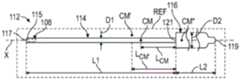
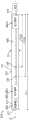
图1至图4示出了示例性内窥镜110,该示例性内窥镜可用于产生体内手术图像。参考图1,内窥镜110可包括针毂组件112和电缆(例如通信)组件113。如图1和图2B中所示出,针毂组件112可包括固定在针毂116中的观测镜114(例如相机或成像杆)。观测镜114从针毂116的远侧端部延伸。观测镜114和针毂116可被尺寸设定成使得针毂组件112相对于参考平面REF基本上对称(例如镜像对称),该参考平面沿组件112的纵(例如中心)轴X延伸,以将组件112分成两个相对的部分,如图2A至图2B中所示出。Figures 1-4 illustrate an
可利用各种技术来对毂组件112进行尺寸设定。参考图2B,并且继续参考图1和图2A,观测镜114可相对于纵轴X在末端(例如远侧)端部117与观测镜114同毂116的远侧端部之间的界面121之间延伸第一长度L1。界面121可建立在观测镜114的近侧端部处或附近。在观测镜114为柔性的具体实现中,第一长度L1对应于观测镜114的最大可配置长度。在省略毂116的具体实现中,第一长度L1可建立在观测镜114的近侧端部与远侧端部之间。在具体实现中,第一长度L1可在大约100毫米(mm)与300mm之间。针毂116可相对于纵轴X在针毂116的相对的近侧端部与远侧端部之间延伸第二长度L2。观测镜114可建立第一直径D1。针毂116可建立第二直径D2。第一长度L1与第二长度L2和/或第一直径D1与第二直径D2可以相同或可以不同。在一些具体实现中,针毂116的长度L2小于观测镜114的长度L1的0.75倍,毂116的直径D2小于观测镜114的直径D1的5倍,并且/或者毂116的重量小于观测镜114的重量的2倍。
毂116和观测镜114可被附接以形成具有质心CM的毂组件112。质心CM可相对于纵轴X建立在纵向位置处。质心CM的纵向位置可相对于纵轴X与沿观测镜114的纵向位置对准。质心CM可相对于纵轴X建立在针毂116远侧。在具体实现中,质心CM可沿纵轴X建立在观测镜114内。在其他具体实现中,针毂组件112可被构造成使得质心可建立在观测镜114附近但偏离该观测镜,如质心CM’(图2A)所示出。内窥镜110可被构造成使得在外科手术期间质心CM可位于患者体内或体外。
毂116和/或观测镜114可以是对称的或非对称的,以建立质心CM。例如,观测镜114可具有曲线几何形状,使得观测镜114的一个或多个部分偏离纵轴X,以建立非对称构型。作为另一示例,毂116内的部件可被布置成使得部件的质心偏离纵轴X。
质心CM可建立在相对于观测镜114和/或针毂116的各种位置处。毂组件112可被构造成使得毂组件112的包括质心CM的一部分可定位在患者体内,以在没有外科医生或助手干预的情况下改善内窥镜110的保持力,但毂组件112的另一部分可定位在患者体外。质心CM可建立在针毂116的远侧端部处、附近或远侧。The center of mass CM may be established at various locations relative to the
质心CM可建立在距第一长度L1的近侧边界距离LCM处。第一长度L1的近侧边界可由观测镜114与毂116的远侧端部之间的界面121建立,或者对于省略毂116的具体实现可由观测镜114的近侧端部建立。毂组件112可被构造成使得质心CM’偏离观测镜114。距离LCM可小于第一长度L1的10%。质心CM可建立在观测镜114与针毂116的远侧端部之间的界面121处。在具体实现中,质心CM”可在毂116内建立在界面121的近侧。毂组件112可被构造成使得距离LCM大于或等于第一长度L1的10%,或者更窄地大于或等于第一长度L1的大约25%。在具体实现中,距离LCM可小于或等于第一长度L1的大约50%。出于本公开的目的,除非另外指示,否则术语“基本上”、“大约”和“约”意指所陈述的值或关系的±10%。利用本文中所公开的技术,包括所公开的尺寸关系和分布,以在内窥镜110未被保持时减小移动或干预的可能性的方式,外科医生或助手可在体内对毂组件112进行定位。The center of mass CM may be established at a distance LCM from the proximal boundary of the first length L1. The proximal boundary of the first length L1 may be established by the
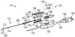
参考图3,并且继续参考图1,电缆组件113可包括第一电缆118(例如微型同轴电缆)、按钮轭120、第二电缆126和连接器128。连接器128可包括端子130,该端子被配置成与外部设备通信,该外部设备诸如显示器或控制设备131(出于说明的目的,在图1中以虚线示出)。在其他具体实现中,内窥镜110与控制设备131无线地通信。针毂组件112或电缆组件113可包括电力供应器133,该电力供应器在操作中向内窥镜110的各种电部件提供电力(出于说明的目的,在图3中以虚线被示出为耦合到电子电路138)。在其他具体实现中,电力由外部设备提供,并且由端子130传送到各种电部件。Referring to FIG. 3 , with continued reference to FIG. 1 , the
观测镜114可包括位于观测镜114的远侧端部部分115上、该远侧端部部分处或附近的成像传感器108,以用于获得手术部位的图像。成像传感器108可以是包括传感器和光学器件的传感器组件。观测镜114可被配置成接收光并且将光引导到或另外朝向邻近观测镜114的远侧端部部分115的区域(例如外科医生正在观察的场景或空间)。光可以从该区域朝向传感器108向回反射。The
观测镜114和每根电缆118、126可以相对刚性或柔性。观测镜114的远侧端部部分115建立内窥镜110的末端117(例如尖端)。观测镜114的包括远侧端部部分115的至少一部分可以是相对柔性的或可弯曲的,并且可以包括例如镍钛诺(Nitinol)材料。将观测镜114构造成相对柔性可以便于对传感器108进行定向,包括例如在拐角周围使传感器108弯曲或转向以及观察手术部位的各种角度。The
第一电缆118可以是同轴电缆(例如微型同轴电缆)。如图1和图4中所示出,第一电缆118可耦合到毂组件112的近侧端部部分119。在一些具体实现中,第一电缆118可在针毂116与按钮轭120之间传送模拟信号。按钮轭120可以使第一电缆118与第二电缆126互连。第二电缆126可以使按钮轭120与连接器128互连。The
按钮轭120可具有一个或多个控制件(例如按钮、转盘、控制杆等),诸如按钮122和按钮124。每个按钮122、124可具有一个或多个功能,诸如图像和视频捕获。每个按钮122、124可针对多种功能进行编程。另外,可基于按钮122、124被按压的次数、按钮122、124被按压多次的时间量以及/或者按钮122、124保持被持续按压的时间量来访问多个功能。
第一电缆118和第二电缆126可具有不同的尺寸。在一些具体实现中,第二电缆126具有大约2英尺的长度,这可以允许按钮轭120在内窥镜110被使用时搁置在表面上,并且可以最小化或另外减小对毂116的静止位置的影响。The
针毂116可包括将观测镜114连接到针毂116的其他部件的毂耦合器134。针毂116可包括各种电子器件123,包括柔性电路板135、电子电路138、光供应器137和光学耦合器136。柔性电路板135可从针毂116穿过观测镜114延伸到传感器108。柔性电路板135可连接到电子电路138。电子电路138可呈印刷电路板的形式,并且可包括一个或多个芯片。电子电路138可被配置成通过同轴电缆(诸如第一电缆118)以模拟信号传输图像数据。在具体实现中,电子器件123中的一个或多个电子器件可结合到按钮轭120中,包括电力供应器133、柔性电路板135、光学耦合器136、光供应器137和/或电子电路138,并且可以省略包括外壳139的单独的毂116。The
观测镜114可被配置成接收光并且将光引导到或朝向邻近观测镜114的远侧端部部分115的区域。光可以直接或间接地从观测镜114被传送到传感器108。例如,光可以从该区域向回反射到传感器108,或者另外朝向该传感器反射。电路138和/或柔性电路板135可连接到光供应器137(例如光源或照明元件)。光源137可以是例如发光二极管(LED),并且可以被配置成并被用于在体内产生照明。光学耦合器136可被配置成将来自光源137的光传送到光纤(例如光导管)103(出于说明的目的,在图3中以虚线示出)。光纤103可被配置成将光从针毂116传输到观测镜114的远侧端部部分115。在其他具体实现中,可以省略光纤103,并且光源137可以定位在针毂116远侧的观测镜114内。在具体实现中,单独的光源可位于观测镜114的远侧端部部分115外部但邻近该远侧端部部分,以照亮手术部位。The
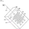
在一些具体实现中,成像传感器308和一个或多个光源316与公共电路板323(例如芯片)集成,或者安装到该公共电路板,以建立电子部件325,如图6中所示出。光源316可被配置成阵列以环绕传感器308,并且可以是单独可控的。在具体实现中,光源316可以是被配置成从单一公共光源327(出于说明的目的,以虚线示出)分支的相应路径。光源316可用于在相对紧凑的布置中改善光的传送。公共光源327可耦合到电路板323或内窥镜的另一部分。电路板323上的光源组316可具有相同或不同的波长,并且可基于包括使用图像特征和/或传感器特征进行反馈的多种因素来控制强度。电组件325可位于本文中所公开的图像传感器的位置中的任一位置处。例如,电组件325可耦合或附接在观测镜114的远侧端部部分115上或附近(图1)。将成像传感器308和光源316组合在同一电路板323上可通过被输送到手术部位的流体(诸如在外科手术期间用于冲洗手术部位的流体)来改善冷却增强。In some implementations,
针毂组件112的各种电子器件可被配置成将图像数据从成像传感器108无线地和/或以数字方式传输到诸如控制设备131的外部设备和/或内窥镜110的另一部件,诸如按钮轭120。其他传感器可结合到内窥镜110中。例如,一个或多个传感器可被配置成感测或测量观测镜114的远侧端部部分115处的各种状况,诸如温度传感器、压力传感器等。在一些具体实现中,加速度计和/或陀螺仪定位在针毂116和/或观测镜114中,以感测内窥镜110的位置和/或定向的变化。The various electronics of
远侧端部部分115的末端117可相对于内窥镜110的中心轴或纵轴以各种角度进行建立。例如,末端117可基本上垂直于观测镜114的纵轴X,如图1和图2A至图2B中所示出。在一些具体实现中,远侧端部部分115’的末端117’建立角度α,该角度横向于观测镜114’的中心轴或纵轴X,如图7中所示出。例如,由传感器108’获得的传感器图像可以以对应于角度α的角度(例如30度)定向。电子电路138’或内窥镜110’的另一部分可使用逻辑进行编程或者另外结合逻辑,以执行捕获图像的校正或平移,从而在传感器108’于手术期间旋转时对捕获图像进行重新定向。The
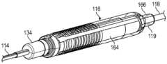
仍然参考图3,针毂116可包括被构造成包封针毂116的部件的外壳139。外壳139可包括协作以包封针毂116的电子器件和其他部件(例如光源137、电路138和光学耦合器136)的第一壳体162和第二壳体164。毂耦合器134可将观测镜114耦合到外壳139的壳体162和164。毂耦合器134可以是单独且相异的部件,或者可以结合到外壳139和/或观测镜114中。Still referring to FIG. 3 , the
如图4中所示出,护罩230可以至少部分或完全地环绕外壳139。护罩230可采取柔性护罩的形式,并且可由诸如铜的导电材料形成。因此,护罩230可采取铜箔的形式。支撑罩166可支撑外壳139和第一电缆118,如图4中所示出(以虚线示出)。As shown in FIG. 4 , shroud 230 may at least partially or completely surround
出于比较目的,图5示出了另一示例性内窥镜410。内窥镜410可具有手持件412和相机杆414。手持件412可被设计成由外科医生或助手保持,并且包括所有控制电子器件。在这些具体实现中,内窥镜410的质心可以显著地返回手持件412中,并且因此可以由助手更广泛地保持,而不是在没有助手引导的情况下保持静止。For comparison purposes, another
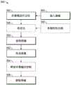
图8以流程图540示出了执行外科手术的示例性方法。方法540可用于执行内窥镜检查。方法540可以与本文中所公开的器械和组件(包括内窥镜110、110’和内窥镜710、810(图12至图13))中的任一者一起使用。所获得的图像可在手术前、手术中和/或手术后使用,并且可用于进行各种外科手术(诸如关节成形术)以恢复关节的功能。在本公开的范围内,可执行比下文列举的步骤更少或更多的步骤,并且所列举的步骤次序不旨在限制本公开。出于说明的目的,参考图9至图11的器械(例如内窥镜)610。FIG. 8 illustrates an exemplary method of performing a surgical procedure in
参考图9,并且继续参考图8,器械610可包括耦合到电缆组件613的毂组件612。毂组件612可包括毂616以及耦合到毂616的观测镜614(例如相机或成像杆)。毂616可具有大致或基本上管状的几何形状,并且可用作对毂组件612进行定位的手柄。毂组件612可包括位于成像杆614的远侧端部部分615的成像传感器608。成像杆614可从毂616延伸到远侧端部部分615。毂616和成像杆614可被附接以建立具有质心CM的毂组件612。质心CM可相对于毂组件612的纵轴X建立在毂616远侧(图10)。毂组件612可被构造成使得质心CM可建立在成像杆614内或附近。毂组件612可根据本文中所公开的技术中的任一种技术来配置。在具体实现中,毂616的长度可小于成像杆614的长度的0.75倍,毂616的重量可小于成像杆614的重量的2倍,并且/或者毂616的直径可小于成像杆614的直径的5倍。Referring to FIG. 9 , with continued reference to FIG. 8 , an instrument 610 may include a hub assembly 612 coupled to a cable assembly 613 . Hub assembly 612 may include a
在步骤542处,器械610可相对于患者的身体B中在手术部位S处的插入点611进行定位。插入点611可以是穿过皮肤形成的切口、孔或患者的身体B中的另一开口。方法540可包括在步骤542之前形成切口。At
参考图10,并且继续参考图8至图9,步骤542可包括在方向D1上移动器械610,以及随后在步骤544处将器械610的一部分插入穿过插入点611。步骤544可发生以使得器械610的该部分位于体内。步骤544可包括将成像杆614的至少远侧端部部分615插入穿过患者的插入点611,以及随后将器械610的质心CM插入穿过插入点611。毂组件612的包括质心CM的一部分可定位在患者体内,而毂组件612的另一部分可定位在患者体外,诸如毂616和/或成像杆614的在质心CM近侧的一部分,包括成像杆614的近侧端部。Referring to FIG. 10 , with continued reference to FIGS. 8-9 , step 542 may include moving instrument 610 in direction D1 , and then inserting a portion of instrument 610 through
在步骤546处,方法540可包括将光传送到成像传感器608。可利用各种技术将光传送到成像传感器608。在具体实现中,步骤546可包括将来自毂616的光进行传送,随后穿过成像杆614,并且随后到达患者的邻近成像杆614的远侧端部部分615的区域。光可以从该区域向回反射到成像传感器608,或者另外朝向该成像传感器反射(也参见图1的毂116、成像传感器108和成像杆114)。在具体实现中,步骤546可包括传送来自邻近成像杆614的远侧端部部分615的一个或多个光源的光。光源可被配置成阵列以环绕成像传感器608(参见例如图6的成像传感器308和光源316)。步骤546可包括在步骤548处单独控制光源以传送光。At
在步骤550处,外科医生或助手可以使器械610通过位于插入点611向内的位置处的成像传感器608而获得一个或多个图像。步骤550可发生在于步骤542处对器械610进行定位以及/或者于步骤546处传送光之后。在于步骤550处获得图像期间,器械610的质心CM可在插入点611的内部或者另外位于体内,并且毂116可位于插入点611的外部或者另外位于体外。在步骤552处,图像可被传送到外部设备(参见例如图1的外部设备131)。At
在步骤554处,当器械610的远侧端部部分615、成像传感器608和/或质心CM位于体内时,外科医生或助手可释放对器械610的控制,如图10中所示出。步骤554可包括释放对毂组件612的控制,使得质心CM可位于体内,并且使得毂116可从插入点611向外从成像杆614基本上悬臂式伸出。出于本公开的目的,术语“基本上”悬臂式伸出意指在插入点611的外部的毂组件112的不超过10%由除了成像杆614之外的装置支撑。步骤554可包括响应于释放对毂组件612的控制,在插入点611处或附近使毂组件612平衡。器械610可在没有被外科医生或助手保持或支撑的情况下保持在适当位置,这可以提高灵活性,并且减少在外科手术中执行其他步骤的时间。At
参考图11,并且继续参考图8,在步骤556处,器械610的位于体内的部分可在方向D2上移动,直到器械610从插入点611撤回并且从患者体内移除为止。步骤556可包括从患者体内撤回成像传感器608、远侧端部部分615和器械610的质心CM。Referring to FIG. 11 , with continued reference to FIG. 8 , at
图12示出了另一示例性器械710。器械710可以是用于获得手术部位的一个或多个图像的内窥镜。器械710可包括针毂组件712,该针毂组件耦合到电缆(例如通信)组件713(出于说明的目的,以虚线示出)。在图12的具体实现中,从毂组件712中省略了单独的毂。Another
毂组件712可包括观测镜714(例如相机或成像杆)。观测镜714可包括主体729,该主体在毂组件712的远侧端部部分715与近侧端部部分719之间沿纵轴X延伸。主体729可具有大致或基本上管状的几何形状,并且可建立内部腔体725。观测镜714可建立第一直径D1。主体729可被尺寸设定成使得第一直径D1在观测镜714的远侧端部部分715与近侧端部部分719之间基本上恒定。The hub assembly 712 may include a scope 714 (eg, a camera or imaging rod). The sight glass 714 can include a body 729 extending along the longitudinal axis X between the
观测镜714可包括被配置成获得手术部位的图像的成像传感器708。成像传感器708可被布置在内腔725内,并且可被布置在观测镜714的远侧端部部分715处,以获得手术部位的一个或多个图像。外科医生或助手可利用观测镜714的一部分作为手柄,以将成像传感器708定位在患者体内的所需位置和定向处。The scope 714 may include an
毂组件710可包括各种电子器件760,包括本文中所公开的电子器件中的任一电子器件,诸如柔性电路板、电子电路、光供应器、光学耦合器和/或电力供应器(参见例如图3)。电子器件760可以集成到单个芯片上以建立电子器件单元,该电子器件单元可以集成或耦合到成像传感器708。电子器件760可被布置在观测镜714的腔体725内的各种位置处。电子器件760可被布置在毂组件712的质心CM的近侧,诸如在观测镜714的近侧端部部分719处或附近。电子器件760可包括位于观测镜714内邻近近侧端部部分719的光源。
质心CM可建立在毂组件712的远侧端部部分715与近侧端部部分719之间(包括在观测镜714内)的纵向位置处。质心CM可建立在距观测镜714的第一长度L1的近侧边界距离LCM处。毂组件712可被构造成使得质心CM可根据本文中所公开的距离LCM与第一长度L1的比率中的任一比率来建立。在具体实现中,毂组件712可被构造成使得距离LCM大于或等于第一长度L1的25%,或者更窄地大于或等于第一长度L1的大约50%。在具体实现中,距离LCM可小于或等于第一长度L1的大约75%。A center of mass CM may be established at a longitudinal location between the
将毂组件712的至少一些、大部分或所有电子器件760和/或其他内部部件布置到观测镜714中可用于相对于毂组件712的近侧端部部分719相对更向远侧地使毂组件712的质心CM移位,这可以在没有外科医生或助手干预的情况下改善器械710的保持力。Arranging at least some, most, or all of the
图13示出了另一示例性器械810。器械810可以是用于获得手术部位的一个或多个图像的内窥镜。器械810可包括耦合到电缆(例如通信)组件813的毂组件812。在图13的具体实现中,省略了单独的毂。Another
器械810可包括被布置在观测镜814的腔体825内的各种位置处的各种电子器件860。电子器件860可包括第一组电子器件860-1和第二组电子器件860-2,该第一组电子器件和该第二组电子器件可包括本文中所公开的电子器件中的任一电子器件。
电子器件860可分布在观测镜814内,以在毂组件812的远侧端部部分815与近侧端部部分819之间的各种位置处建立质心CM。质心CM可建立在远侧端部部分815与近侧端部部分819之间(包括在观测镜814内)的纵向位置处。第一组电子器件860-1可被布置在毂组件812的质心CM的远侧。第二组电子器件860-2可被布置在质心CM近侧。第一组电子器件860-1可被布置在观测镜814的远侧端部部分815处或附近。第二组电子器件860-2可被布置在观测镜814的近侧端部部分819处或附近。在具体实现中,省略了第二组电子器件860-2,使得毂组件812的所有电子器件基本上被布置在成像杆814的远侧半部中。电子器件860-1可包括诸如LED的光源,该光源可定位在成像传感器808附近和近侧。Electronics 860 may be distributed within
质心CM可建立在毂组件812的远侧端部部分815与近侧端部部分819之间(包括在观测镜814内)的纵向位置处。质心CM可建立在距观测镜814的第一长度L1的近侧边界距离LCM处。毂组件812可被构造成使得质心CM可根据本文中所公开的距离LCM与第一长度L1的比率中的任一比率来建立。在具体实现中,毂组件812可被配置成使得距离LCM大于或等于第一长度L1的25%,更窄地大于或等于第一长度L1的大约50%,或者甚至更窄地大于或等于第一长度L1的大约75%。在具体实现中,距离LCM可小于或等于第一长度L1的大约90%。A center of mass CM may be established at a longitudinal location between the distal end portion 815 and the
将毂组件812的至少一些、大部分或所有电子器件860和/或其他内部部件布置在器械810的远侧端部部分815附近可用于相对于毂组件812的近侧端部部分819相对更向远侧地使毂组件812的质心CM移位,这可以在没有外科医生或助手干预的情况下改善器械810的保持力。Arranging at least some, most, or all of the electronics 860 and/or other internal components of the
参考图14,器械910可包括电子器件960。电子器件960中的一个或多个电子器件可结合到电缆组件913中。电缆组件913可包括按钮轭920,该按钮轭可结合电子器件960-2。电子器件960-2可包括本文中所公开的电子器件中的任一电子器件,包括电力供应器133、柔性电路板135、光学耦合器136、光供应器137和/或电子电路138(图3)。可省略包括包封电子器件的外壳的单独的毂。器械910可包括邻近成像杆914的远侧端部部分915的电子器件960-1,或者电子器件960-1可被省略和/或结合到按钮轭920中。Referring to FIG. 14 ,
本公开的新颖设备和方法在于内窥镜检查期间获得患者解剖结构的图像中提供了多功能性。所公开的器械可被构造成允许器械被插入患者体内,并且在没有被外科医生或助手保持或支撑的情况下保持在适当位置。所公开的器械可被构造成具有质心,该质心在没有外科医生或助手干预的情况下提高了器械的保持力,这可以减少执行外科手术的复杂性和时间。The novel devices and methods of the present disclosure provide versatility in obtaining images of a patient's anatomy during an endoscopy. The disclosed instruments can be configured to allow the instrument to be inserted into a patient and held in place without being held or supported by a surgeon or assistant. The disclosed instruments can be configured with a center of mass that improves instrument retention without intervention by a surgeon or assistant, which can reduce the complexity and time of performing a surgical procedure.
尽管不同的非限制性实施方案被示出为具有特定部件或步骤,但本公开的实施方案不限于那些特定组合。有可能将来自非限制性实施方案中的任一实施方案的部件或特征中的一些与来自其他非限制性实施方案中的任一实施方案的特征或部件组合使用。Although various non-limiting embodiments are shown with particular components or steps, embodiments of the present disclosure are not limited to those particular combinations. It is possible to use some of the components or features from any of the non-limiting embodiments in combination with features or features from any of the other non-limiting embodiments.
前面的描述应被解释为说明性的,而不应以任何限制性意义进行解释。本领域的普通技术人员将理解,某些修改可以属于本公开的范围。由于这些原因,应该研究以下权利要求来确定本公开的真实范围和内容。The foregoing description should be interpreted as illustrative and not in any restrictive sense. A person of ordinary skill in this art would understand that certain modifications may come within the scope of this disclosure. For these reasons, the following claims should be studied to determine the true scope and content of this disclosure.
Claims (37)
Translated fromChineseApplications Claiming Priority (3)
| Application Number | Priority Date | Filing Date | Title |
|---|---|---|---|
| US202063065037P | 2020-08-13 | 2020-08-13 | |
| US63/065,037 | 2020-08-13 | ||
| PCT/US2021/041397WO2022035538A1 (en) | 2020-08-13 | 2021-07-13 | Endoscopic instrument |
Publications (1)
| Publication Number | Publication Date |
|---|---|
| CN116133575Atrue CN116133575A (en) | 2023-05-16 |
Family
ID=77207274
Family Applications (1)
| Application Number | Title | Priority Date | Filing Date |
|---|---|---|---|
| CN202180055718.9APendingCN116133575A (en) | 2020-08-13 | 2021-07-13 | Endoscopic instruments |
Country Status (8)
| Country | Link |
|---|---|
| US (3) | US11690503B2 (en) |
| EP (2) | EP4309565A3 (en) |
| JP (2) | JP7585459B2 (en) |
| KR (2) | KR102737469B1 (en) |
| CN (1) | CN116133575A (en) |
| AU (1) | AU2021324569A1 (en) |
| CA (1) | CA3187133A1 (en) |
| WO (1) | WO2022035538A1 (en) |
Families Citing this family (1)
| Publication number | Priority date | Publication date | Assignee | Title |
|---|---|---|---|---|
| US12268359B2 (en)* | 2023-03-13 | 2025-04-08 | Endoluxe Inc. | Handheld unit for endoscopy, laparoscopy, and other scopic procedures and methods of manufacture and use thereof |
Family Cites Families (28)
| Publication number | Priority date | Publication date | Assignee | Title |
|---|---|---|---|---|
| US4718406A (en)* | 1982-06-28 | 1988-01-12 | The United States Of America As Represented By The Secretary Of The Navy | Fiber optics image scope (micro-endoscope), ureteroscope |
| US4947828A (en)* | 1989-04-17 | 1990-08-14 | Schott Fiber Optics | Endoscope connector |
| WO1994010920A1 (en)* | 1992-11-06 | 1994-05-26 | Clarus Medical Systems, Inc. | Surgical instrument incorporating fiber optic viewing systems |
| US5653677A (en)* | 1994-04-12 | 1997-08-05 | Fuji Photo Optical Co. Ltd | Electronic endoscope apparatus with imaging unit separable therefrom |
| US20050182297A1 (en)* | 1996-10-04 | 2005-08-18 | Dietrich Gravenstein | Imaging scope |
| US6319195B1 (en)* | 1998-10-20 | 2001-11-20 | Nihon Kohden Corporation | Endoscope |
| JP3220746B2 (en) | 1998-11-06 | 2001-10-22 | 日本光電工業株式会社 | Endoscope for endotracheal tube intubation |
| JP2002045329A (en)* | 2000-08-01 | 2002-02-12 | Fuji Photo Film Co Ltd | Fluorescent device displaying diagnostic image |
| JP4098667B2 (en) | 2003-05-14 | 2008-06-11 | オリンパス株式会社 | Electric bending endoscope |
| WO2005021066A1 (en)* | 2003-08-21 | 2005-03-10 | Tyco Healthcare Group Lp | Surgical instrument |
| JP2005131162A (en) | 2003-10-31 | 2005-05-26 | Olympus Corp | Endoscope |
| JP2005204944A (en)* | 2004-01-22 | 2005-08-04 | Chinontec Kk | Endoscope |
| JP4455088B2 (en) | 2004-02-12 | 2010-04-21 | オリンパス株式会社 | Medical device holding device |
| US8287446B2 (en)* | 2006-04-18 | 2012-10-16 | Avantis Medical Systems, Inc. | Vibratory device, endoscope having such a device, method for configuring an endoscope, and method of reducing looping of an endoscope |
| JP2007196017A (en) | 2007-04-20 | 2007-08-09 | Olympus Corp | Endoscope |
| DE102008024789A1 (en)* | 2008-05-21 | 2009-12-03 | Richard Wolf Gmbh | Stereo endoscope |
| US7910834B2 (en)* | 2008-05-27 | 2011-03-22 | Voltstar Technologies, Inc. | Energy saving cable assemblies |
| US20100152762A1 (en)* | 2008-12-16 | 2010-06-17 | Mark Joseph L | Tissue removal system with multi-directional foot actuator assembly for neurosurgical and spinal surgery applications |
| JP6321939B2 (en)* | 2013-10-21 | 2018-05-09 | オリンパス株式会社 | Scanner, scanning illumination device, and scanning observation device |
| WO2015157727A2 (en)* | 2014-04-10 | 2015-10-15 | Avendo Imaging Systems | Tethered endoscope |
| US10463399B2 (en)* | 2014-11-06 | 2019-11-05 | Asimion Inc. | Visually assisted entry of a Veress needle with a tapered videoscope for microlaparoscopy |
| US20170035404A1 (en)* | 2015-04-24 | 2017-02-09 | Invuity, Inc. | Surgical instrument compatible with operating room equipment |
| JP7088789B2 (en)* | 2018-08-31 | 2022-06-21 | 株式会社モリタ製作所 | Imaging device |
| US10687698B2 (en)* | 2018-09-12 | 2020-06-23 | Enlightenvue Llc | Direct endoluminal- and/or endovascular-illumination systems and methods of use thereof |
| DE112020000510T5 (en)* | 2019-01-23 | 2022-03-17 | Scanlan International, Inc. | surgical instrument |
| BR102019017389A2 (en)* | 2019-08-21 | 2021-03-02 | Marisa Toyomi Miyazaki | transilluminator for mapping facial blood vessels |
| JP6720426B1 (en)* | 2020-02-05 | 2020-07-08 | 太 中島 | Intubation device and light emitting unit |
| CN111808916A (en)* | 2020-07-24 | 2020-10-23 | 上海安翰医疗技术有限公司 | Trypsin detection film, preparation method and application thereof and trypsin detection kit |
- 2021
- 2021-07-13USUS17/374,328patent/US11690503B2/enactiveActive
- 2021-07-13AUAU2021324569Apatent/AU2021324569A1/enactivePending
- 2021-07-13EPEP23215123.3Apatent/EP4309565A3/enactivePending
- 2021-07-13CACA3187133Apatent/CA3187133A1/enactivePending
- 2021-07-13WOPCT/US2021/041397patent/WO2022035538A1/ennot_activeCeased
- 2021-07-13EPEP21749959.9Apatent/EP4195997B1/enactiveActive
- 2021-07-13JPJP2023509563Apatent/JP7585459B2/enactiveActive
- 2021-07-13CNCN202180055718.9Apatent/CN116133575A/enactivePending
- 2021-07-13KRKR1020237008292Apatent/KR102737469B1/enactiveActive
- 2021-07-13KRKR1020247039659Apatent/KR20250004018A/enactivePending
- 2023
- 2023-03-31USUS18/193,887patent/US12256901B2/enactiveActive
- 2024
- 2024-10-29JPJP2024189618Apatent/JP2025010271A/enactivePending
- 2025
- 2025-02-06USUS19/046,730patent/US20250176810A1/enactivePending
Also Published As
| Publication number | Publication date |
|---|---|
| US11690503B2 (en) | 2023-07-04 |
| KR20250004018A (en) | 2025-01-07 |
| KR102737469B1 (en) | 2024-12-04 |
| EP4309565A3 (en) | 2024-03-27 |
| CA3187133A1 (en) | 2022-02-17 |
| EP4195997A1 (en) | 2023-06-21 |
| AU2021324569A1 (en) | 2023-02-23 |
| EP4195997C0 (en) | 2024-01-31 |
| EP4309565A2 (en) | 2024-01-24 |
| US12256901B2 (en) | 2025-03-25 |
| US20230277048A1 (en) | 2023-09-07 |
| JP2025010271A (en) | 2025-01-20 |
| US20220047153A1 (en) | 2022-02-17 |
| WO2022035538A1 (en) | 2022-02-17 |
| JP2023537529A (en) | 2023-09-01 |
| JP7585459B2 (en) | 2024-11-18 |
| EP4195997B1 (en) | 2024-01-31 |
| KR20230051226A (en) | 2023-04-17 |
| US20250176810A1 (en) | 2025-06-05 |
Similar Documents
| Publication | Publication Date | Title |
|---|---|---|
| CN210472105U (en) | Endoscopic systems and endoscopes with an off-center field of view | |
| US20220304550A1 (en) | Systems and methods for modular endoscope | |
| KR101814830B1 (en) | Small diameter video camera heads and visualization probes and medical devices containing them | |
| US20140320621A1 (en) | Small diameter video camera heads and visualization probes and medical devices containing them | |
| JPH01155826A (en) | Endoscope equipped with needle-like probe and video display apparatus | |
| US6506150B1 (en) | Self-retaining endoscope | |
| CN103348470A (en) | Flexible electronic circuit board for multi-camera endoscopy | |
| US20250176810A1 (en) | Endoscopic instrument | |
| JP2023515596A (en) | Multifunctional catheter | |
| CN110575603A (en) | A guidewire delivery device with visual function | |
| US20240260820A1 (en) | Systems and methods for configurable endoscope bending section | |
| CN113499017A (en) | Medical infrared electronic fiber endoscope | |
| HK40080155A (en) | Systems and methods for modular endoscope | |
| JPWO2022035538A5 (en) |
Legal Events
| Date | Code | Title | Description |
|---|---|---|---|
| PB01 | Publication | ||
| PB01 | Publication | ||
| SE01 | Entry into force of request for substantive examination | ||
| SE01 | Entry into force of request for substantive examination |