CN116129736A - Electronic equipment - Google Patents
Electronic equipmentDownload PDFInfo
- Publication number
- CN116129736A CN116129736ACN202111347109.9ACN202111347109ACN116129736ACN 116129736 ACN116129736 ACN 116129736ACN 202111347109 ACN202111347109 ACN 202111347109ACN 116129736 ACN116129736 ACN 116129736A
- Authority
- CN
- China
- Prior art keywords
- display panel
- flexible display
- hole
- electronic device
- backplane
- Prior art date
- Legal status (The legal status is an assumption and is not a legal conclusion. Google has not performed a legal analysis and makes no representation as to the accuracy of the status listed.)
- Pending
Links
Images


Classifications
- G—PHYSICS
- G09—EDUCATION; CRYPTOGRAPHY; DISPLAY; ADVERTISING; SEALS
- G09F—DISPLAYING; ADVERTISING; SIGNS; LABELS OR NAME-PLATES; SEALS
- G09F9/00—Indicating arrangements for variable information in which the information is built-up on a support by selection or combination of individual elements
- G09F9/30—Indicating arrangements for variable information in which the information is built-up on a support by selection or combination of individual elements in which the desired character or characters are formed by combining individual elements
- G—PHYSICS
- G06—COMPUTING OR CALCULATING; COUNTING
- G06F—ELECTRIC DIGITAL DATA PROCESSING
- G06F1/00—Details not covered by groups G06F3/00 - G06F13/00 and G06F21/00
- G06F1/16—Constructional details or arrangements
- G—PHYSICS
- G06—COMPUTING OR CALCULATING; COUNTING
- G06F—ELECTRIC DIGITAL DATA PROCESSING
- G06F1/00—Details not covered by groups G06F3/00 - G06F13/00 and G06F21/00
- G06F1/16—Constructional details or arrangements
- G06F1/1613—Constructional details or arrangements for portable computers
- G06F1/1633—Constructional details or arrangements of portable computers not specific to the type of enclosures covered by groups G06F1/1615 - G06F1/1626
- G06F1/1637—Details related to the display arrangement, including those related to the mounting of the display in the housing
- G06F1/1652—Details related to the display arrangement, including those related to the mounting of the display in the housing the display being flexible, e.g. mimicking a sheet of paper, or rollable
- G—PHYSICS
- G06—COMPUTING OR CALCULATING; COUNTING
- G06F—ELECTRIC DIGITAL DATA PROCESSING
- G06F1/00—Details not covered by groups G06F3/00 - G06F13/00 and G06F21/00
- G06F1/16—Constructional details or arrangements
- G06F1/1613—Constructional details or arrangements for portable computers
- G06F1/1633—Constructional details or arrangements of portable computers not specific to the type of enclosures covered by groups G06F1/1615 - G06F1/1626
- G06F1/1675—Miscellaneous details related to the relative movement between the different enclosures or enclosure parts
- G06F1/1681—Details related solely to hinges
- G—PHYSICS
- G09—EDUCATION; CRYPTOGRAPHY; DISPLAY; ADVERTISING; SEALS
- G09F—DISPLAYING; ADVERTISING; SIGNS; LABELS OR NAME-PLATES; SEALS
- G09F9/00—Indicating arrangements for variable information in which the information is built-up on a support by selection or combination of individual elements
- G09F9/30—Indicating arrangements for variable information in which the information is built-up on a support by selection or combination of individual elements in which the desired character or characters are formed by combining individual elements
- G09F9/301—Indicating arrangements for variable information in which the information is built-up on a support by selection or combination of individual elements in which the desired character or characters are formed by combining individual elements flexible foldable or roll-able electronic displays, e.g. thin LCD, OLED
- H—ELECTRICITY
- H04—ELECTRIC COMMUNICATION TECHNIQUE
- H04M—TELEPHONIC COMMUNICATION
- H04M1/00—Substation equipment, e.g. for use by subscribers
- H04M1/02—Constructional features of telephone sets
- H—ELECTRICITY
- H04—ELECTRIC COMMUNICATION TECHNIQUE
- H04M—TELEPHONIC COMMUNICATION
- H04M1/00—Substation equipment, e.g. for use by subscribers
- H04M1/02—Constructional features of telephone sets
- H04M1/0202—Portable telephone sets, e.g. cordless phones, mobile phones or bar type handsets
- H04M1/026—Details of the structure or mounting of specific components
- H04M1/0266—Details of the structure or mounting of specific components for a display module assembly
- H04M1/0268—Details of the structure or mounting of specific components for a display module assembly including a flexible display panel
Landscapes
- Engineering & Computer Science (AREA)
- Theoretical Computer Science (AREA)
- Physics & Mathematics (AREA)
- General Physics & Mathematics (AREA)
- Computer Hardware Design (AREA)
- Human Computer Interaction (AREA)
- General Engineering & Computer Science (AREA)
- Signal Processing (AREA)
- Devices For Indicating Variable Information By Combining Individual Elements (AREA)
Abstract
Description
Translated fromChinese技术领域technical field
本申请涉及电子设备的技术领域。The present application relates to the technical field of electronic equipment.
背景技术Background technique
随着显示技术的发展,可折叠的电子设备也得到了越来越多用户的认可。而随着折叠次数的增加,可折叠的电子设备的柔性显示面板也容易出现碎亮点、黑斑、横纹等显示缺陷,从而影响电子设备的使用寿命。With the development of display technology, foldable electronic devices have also been recognized by more and more users. As the number of folding times increases, the flexible display panel of the foldable electronic device is also prone to display defects such as broken bright spots, black spots, and horizontal lines, thereby affecting the service life of the electronic device.
发明内容Contents of the invention
有鉴于此,本申请提供一种电子设备,以解决现有可折叠的电子设备容易出现显示缺陷或者使用寿命较短的问题。In view of this, the present application provides an electronic device to solve the problem that existing foldable electronic devices are prone to display defects or have a short service life.
第一方面,本申请提供了一种电子设备,包括柔性显示面板、背板和转轴,背板设于柔性显示面板和转轴之间。柔性显示面板包括相连的展开部和弯折部,弯折部用于供柔性显示面板实现弯折。背板设有第一盲孔,第一盲孔开设于背板的一侧并且远离柔性显示面板。转轴具有缝隙。以柔性显示面板的表面作为参照面,第一盲孔在参照面上的投影与缝隙在参照面上的投影至少部分重叠。应当理解,通过在背板上开设第一盲孔,可以降低背板的弯折力,以避免柔性显示面板出现碎亮点、黑斑、坏点、横纹等显示缺陷,由此可以提高使用该背板的电子设备的使用寿命。此外,背板之朝向柔性显示面板的一侧并没有开孔,由此可以提高背板的抗挤压性能。In a first aspect, the present application provides an electronic device, including a flexible display panel, a backplane and a rotating shaft, and the backplane is arranged between the flexible display panel and the rotating shaft. The flexible display panel includes a connected unfolding part and a bending part, and the bending part is used for bending the flexible display panel. The backplane is provided with a first blind hole, and the first blind hole is opened on one side of the backplane and away from the flexible display panel. The rotating shaft has a gap. Taking the surface of the flexible display panel as a reference plane, the projection of the first blind hole on the reference plane at least partially overlaps the projection of the slit on the reference plane. It should be understood that by opening the first blind hole on the backplane, the bending force of the backplane can be reduced, so as to avoid display defects such as broken bright spots, dark spots, dead pixels, and horizontal lines on the flexible display panel, thereby improving the use of the flexible display panel. The service life of the electronics on the backplane. In addition, there is no opening on the side of the backplane facing the flexible display panel, thereby improving the anti-extrusion performance of the backplane.
在一些方式中,背板的厚度可以为30μm~200μm,第一盲孔的深度可以小于或者等于195μm。基于此,通过对第一盲孔的形状和深度、背板的厚度等的调整,可以适应性调整背板的弯折力,以便于应用到电子设备中。In some manners, the thickness of the back plate may be 30 μm˜200 μm, and the depth of the first blind hole may be less than or equal to 195 μm. Based on this, by adjusting the shape and depth of the first blind hole, the thickness of the back plate, etc., the bending force of the back plate can be adaptively adjusted, so as to be applied to electronic devices.
在一些方式中,相邻的第一盲孔之间的距离可以为5μm~100μm。基于此,通过对第一盲孔之间的距离的调整,可以适应性调整背板的弯折力,以便于应用到电子设备中。In some manners, the distance between adjacent first blind holes may be 5 μm˜100 μm. Based on this, by adjusting the distance between the first blind holes, the bending force of the backplane can be adaptively adjusted, so as to be applied to electronic devices.
在一些方式中,沿着第一方向,第一盲孔包括依次连通的第一环形区、第一连接区和第二环形区,第一方向为电子设备的长度方向;沿着第二方向,第一环形区、第二环形区的尺寸均大于第一连接区的尺寸,第二方向垂直于第一方向。基于此,该第一环形区和第二环形区可以释放背板的内应力,该连接部则可以降低第一盲孔在整体上的开孔面积,以提高背板的抗挤压力。In some ways, along the first direction, the first blind hole includes a first annular area, a first connection area and a second annular area that are sequentially connected, and the first direction is the length direction of the electronic device; along the second direction, The sizes of the first ring area and the second ring area are larger than the size of the first connection area, and the second direction is perpendicular to the first direction. Based on this, the first annular area and the second annular area can release the internal stress of the back plate, and the connecting portion can reduce the overall opening area of the first blind hole to improve the extrusion resistance of the back plate.
在一些方式中,背板还设有第一通孔,第一通孔与第一盲孔间隔设置。以柔性显示面板的表面作为参照面,第一通孔在参照面上的投影与缝隙在参照面的投影相间隔。应当理解,基于第一盲孔和第一通孔的配合,背板在朝向柔性显示面板的一侧的总开孔面积较小,即背板之朝向柔性显示面板的一面相对平整,因此还可以在一定程度上防止光学胶层等结构挤入背板,以避免电子设备出现横纹等显示缺陷。In some manners, the backplane is further provided with a first through hole, and the first through hole is spaced apart from the first blind hole. Taking the surface of the flexible display panel as a reference plane, the projection of the first through hole on the reference plane is spaced apart from the projection of the slit on the reference plane. It should be understood that based on the cooperation of the first blind hole and the first through hole, the total opening area of the backplane on the side facing the flexible display panel is relatively small, that is, the side of the backplane facing the flexible display panel is relatively flat, so it can also To a certain extent, prevent structures such as optical adhesive layers from squeezing into the backplane, so as to avoid display defects such as horizontal stripes in electronic devices.
在一些方式中,以柔性显示面板的表面作为参照面,第一通孔在参照面上的投影位于柔性显示面板的弯折部上。基于此,该第一通孔并不会直接与转轴的缝隙正对。当用户按压柔性显示面板之对应第一通孔的区域时,可以通过转轴来对柔性显示面板提供一定的支撑力,以避免柔性显示面板出现碎亮点、黑斑、坏点等显示缺陷。In some manners, the surface of the flexible display panel is used as a reference surface, and the projection of the first through hole on the reference surface is located on the bending portion of the flexible display panel. Based on this, the first through hole does not directly face the gap of the rotating shaft. When the user presses the area of the flexible display panel corresponding to the first through hole, a certain support force can be provided to the flexible display panel through the rotating shaft, so as to avoid display defects such as broken bright spots, dark spots, and dead pixels on the flexible display panel.
在一些方式中,相邻的第一盲孔和第一通孔之间的距离可以为5μm~100μm。基于此,通过对第一盲孔之间的距离的调整,同样可以适应性调整背板的弯折力,以便于应用到电子设备中。In some manners, the distance between adjacent first blind holes and first through holes may be 5 μm˜100 μm. Based on this, by adjusting the distance between the first blind holes, the bending force of the backplane can also be adaptively adjusted, so as to be applied to electronic devices.
在一些方式中,背板还开设有第二盲孔,第二盲孔位于背板的一侧并且远离柔性显示面板;以柔性显示面板的表面为参照面,第二盲孔在参照面上的投影位于展开部。应当理解,基于该第二盲孔,可以降低背板的重量,由此可以在整体上降低电子设备的重量,以实现电子设备的轻化。In some ways, the backplane is also provided with a second blind hole, and the second blind hole is located on one side of the backplane and away from the flexible display panel; taking the surface of the flexible display panel as a reference plane, the second blind hole is on the reference plane The projection is in the expansion. It should be understood that based on the second blind hole, the weight of the backplane can be reduced, thereby reducing the weight of the electronic device as a whole, so as to realize the weight reduction of the electronic device.
在一些方式中,背板还开设有第二通孔,沿着柔性显示面板到转轴的方向,第二通孔具有第一孔径和第二孔径,第一孔径小于第二孔径。基于此,可以降低背板的重量,以便于背板适用在电子设备中。In some manners, the backplane is further provided with a second through hole. Along the direction from the flexible display panel to the rotating shaft, the second through hole has a first diameter and a second diameter, and the first diameter is smaller than the second diameter. Based on this, the weight of the backplane can be reduced so that the backplane can be used in electronic equipment.
在一些方式中,第一孔径可以小于或者等于300μm。应当理解,一般用户的手指的指甲厚度为0.3mm~0.8mm,该厚度一般是大于第二通孔的第一孔径。基于此,当用户进行触控操作时,即使用户手指的指甲接触到柔性显示面板之对应第二通孔的区域,背板仍可以对柔性显示面板提供一定的支撑力,以避免柔性显示面板出现碎亮点、黑斑、坏点等显示缺陷。In some aspects, the first pore size may be less than or equal to 300 μm. It should be understood that the thickness of a fingernail of a general user is 0.3mm˜0.8mm, and the thickness is generally greater than the first diameter of the second through hole. Based on this, when the user performs a touch operation, even if the nail of the user's finger touches the area corresponding to the second through hole of the flexible display panel, the backplane can still provide a certain supporting force for the flexible display panel, so as to prevent the flexible display panel from appearing. Broken bright spots, dark spots, dead pixels and other display defects.
第二方面,本申请实施例还提供了另一种电子设备,包括柔性显示面板、背板和转轴,背板设于柔性显示面板和转轴之间。柔性显示面板包括相连的展开部和弯折部,弯折部用于供柔性显示面板实现弯折。背板设有第二通孔,第二通孔开设于背板的一侧并且远离柔性显示面板;沿着柔性显示面板到转轴的方向,第二通孔具有第一孔径和第二孔径,第一孔径小于第二孔径。转轴具有缝隙;以柔性显示面板的表面作为参照面,第二通孔在参照面上的投影与缝隙在参照面上的投影至少部分重叠。应当理解,该第二通孔同样可以减小背板弯折时的局部应力,以便于背板弯折。而由于该第二通孔的第一孔径较小,可以在一定程度上防止光学胶层等结构挤入背板,以提高背板的抗挤压性能。In a second aspect, the embodiment of the present application also provides another electronic device, including a flexible display panel, a backplane, and a rotating shaft, and the backplane is arranged between the flexible display panel and the rotating shaft. The flexible display panel includes a connected unfolding part and a bending part, and the bending part is used for bending the flexible display panel. The backplane is provided with a second through hole, and the second throughhole is opened on one side of the backplane and away from the flexible display panel; along the direction from the flexible display panel to the rotating shaft, the second throughhole has a first aperture and a second aperture, and the second throughhole has a first aperture and a second aperture. The first aperture is smaller than the second aperture. The rotating shaft has a gap; taking the surface of the flexible display panel as a reference plane, the projection of the second through hole on the reference plane at least partially overlaps with the projection of the gap on the reference plane. It should be understood that the second through hole can also reduce the local stress when the back plate is bent, so as to facilitate the bending of the back plate. Since the first aperture of the second through hole is relatively small, structures such as the optical adhesive layer can be prevented from intruding into the backplane to a certain extent, so as to improve the anti-extrusion performance of the backplane.
在一些方式中,第二通孔的第一孔径可以小于或者等于300μm。应当理解,一般用户的手指的指甲厚度为0.3mm~0.8mm,该厚度一般是大于第二通孔的第一孔径。基于此,当用户进行触控操作时,即使用户手指的指甲接触到柔性显示面板之对应第二通孔的区域,背板仍可以对柔性显示面板提供一定的支撑力,以避免柔性显示面板出现碎亮点、黑斑、坏点等显示缺陷。In some manners, the first diameter of the second through hole may be less than or equal to 300 μm. It should be understood that the thickness of a fingernail of a general user is 0.3mm˜0.8mm, and the thickness is generally greater than the first diameter of the second through hole. Based on this, when the user performs a touch operation, even if the nail of the user's finger touches the area corresponding to the second through hole of the flexible display panel, the backplane can still provide a certain supporting force for the flexible display panel, so as to prevent the flexible display panel from appearing. Broken bright spots, dark spots, dead pixels and other display defects.
在一些方式中,相邻的第二通孔之间的距离可以为5μm~100μm。基于此,通过对第二通孔的距离的调整,可以适应性调整背板的弯折力,以便于应用到电子设备中。In some manners, the distance between adjacent second through holes may be 5 μm˜100 μm. Based on this, by adjusting the distance of the second through hole, the bending force of the back plate can be adaptively adjusted, so as to be applied to electronic devices.
在一些方式中,以柔性显示面板的表面作为参照面,第二通孔在参照面上的投影位于弯折部上,以降低背板的弯折力。In some manners, the surface of the flexible display panel is used as a reference surface, and the projection of the second through hole on the reference surface is located on the bending portion, so as to reduce the bending force of the backplane.
在一些方式中,以柔性显示面板的表面作为参照面,第二通孔在参照面上的投影还位于展开部上,以降低背板的重量。In some manners, the surface of the flexible display panel is used as a reference surface, and the projection of the second through hole on the reference surface is also located on the expanded portion, so as to reduce the weight of the backplane.
在一些方式中,背板还开设有第二盲孔,第二盲孔位于背板的一侧并且远离柔性显示面板;以柔性显示面板的表面为参照面,第二盲孔在参照面上的投影位于展开部上。基于该第二盲孔,同样可以降低背板的重量,以实现电子设备的轻化。In some ways, the backplane is also provided with a second blind hole, and the second blind hole is located on one side of the backplane and away from the flexible display panel; taking the surface of the flexible display panel as a reference plane, the second blind hole is on the reference plane The projection is on the expansion. Based on the second blind hole, the weight of the backplane can also be reduced, so as to realize the weight reduction of electronic equipment.
在一些方式中,沿着第一方向,第一通孔包括依次连通的第三环形区、第二连接区和第四环形区,第一方向为电子设备的长度方向;沿着第二方向,第三环形区、第四环形区的尺寸均大于第二连接区的尺寸,第二方向垂直于第一方向。基于此,第三环形区和第四环形区可以释放背板的内应力,以降低背板的弯折力。该第二连接区则可以降低第一通孔在整体上的开孔面积,以在一定程度上防止光学胶层等结构挤入背板,由此可以避免电子设备出现横纹等显示缺陷。In some manners, along the first direction, the first through hole includes a third annular area, a second connection area and a fourth annular area that are connected in sequence, and the first direction is the length direction of the electronic device; along the second direction, Sizes of the third ring area and the fourth ring area are larger than the size of the second connection area, and the second direction is perpendicular to the first direction. Based on this, the third annular area and the fourth annular area can release the internal stress of the back plate, so as to reduce the bending force of the back plate. The second connection area can reduce the overall opening area of the first through hole, so as to prevent structures such as the optical adhesive layer from intruding into the backplane to a certain extent, thereby avoiding display defects such as horizontal stripes in the electronic device.
在一些方式中,相邻的第二通孔和第一通孔之间的距离可以为5μm~100μm。基于此,通过对第二通孔和第一通孔之间的距离的调整,同样可以适应性调整背板的弯折力,以便于应用到电子设备中。In some manners, the distance between adjacent second through holes and first through holes may be 5 μm˜100 μm. Based on this, by adjusting the distance between the second through hole and the first through hole, the bending force of the backplane can also be adaptively adjusted, so as to be applied to electronic devices.
在一些方式中,电子设备还包括光学胶层,光学胶层位于柔性显示面板和背板之间。In some manners, the electronic device further includes an optical adhesive layer, and the optical adhesive layer is located between the flexible display panel and the backplane.
在一些方式中,第一盲孔的截面形状包括梯形、倒梯形、五边形、矩形、工字形、十字形、弓形或者自由曲面形。In some manners, the cross-sectional shape of the first blind hole includes trapezoid, inverted trapezoid, pentagon, rectangle, I-shape, cross, bow or free-form surface.
在一些方式中,背板为金属背板、金属基复合材料背板、多层金属复合材料背板或者非金属材料背板。In some embodiments, the backplane is a metal backplane, a metal matrix composite material backplane, a multilayer metal composite material backplane or a non-metal material backplane.
第三方面,本申请还提供一种背板的加工方法,加工方法包括:对背板中起拱部分进行局部退火,退火温度为0.5Tb;其中,Tb为金属再结晶温度。In a third aspect, the present application also provides a processing method of the backplane, the processing method comprising: performing local annealing on the arched part of the backplane, and the annealing temperature is 0.5Tb; wherein, Tb is the metal recrystallization temperature.
第四方面,本申请还提供一种背板的加工方法,加工方法包括:以不锈钢电极作为阴极、背板作为阳极,将背板放入电解液中进行电解。In a fourth aspect, the present application also provides a method for processing a backplane. The processing method includes: using a stainless steel electrode as a cathode and the backplane as an anode, and putting the backplane into an electrolyte solution for electrolysis.
在一些方式中,电解液包括高氯酸和乙酸,高氯酸:乙酸=1:15。In some modes, the electrolyte solution includes perchloric acid and acetic acid, perchloric acid: acetic acid = 1:15.
本申请通过在背板上设置第一盲孔,在确保背板的弯折性能的同时,可以使背板具有合适的抗挤压性能并且可以在一定程度上防止光学胶等挤入背板,以避免柔性显示面板出现碎亮点、黑斑、坏点或者横纹等显示缺陷,提高电子设备的弯折性能和弯折寿命。In this application, by setting the first blind hole on the backplane, while ensuring the bending performance of the backplane, it can make the backplane have suitable anti-extrusion performance and prevent optical glue from being squeezed into the backplane to a certain extent. To avoid display defects such as broken bright spots, dark spots, dead pixels or horizontal stripes on the flexible display panel, and improve the bending performance and bending life of the electronic device.
附图说明Description of drawings
图1为一般的可折叠的电子设备的示意图。FIG. 1 is a schematic diagram of a general foldable electronic device.
图2为本申请一实施例的柔性显示面板、背板和转轴的示意图。FIG. 2 is a schematic diagram of a flexible display panel, a backplane and a rotating shaft according to an embodiment of the present application.
图3为本申请一实施例的电子设备的局部剖视图。FIG. 3 is a partial cross-sectional view of an electronic device according to an embodiment of the present application.
图4为本申请一实施例的带有第一盲孔的背板的局部示意图。FIG. 4 is a partial schematic diagram of a backplane with a first blind hole according to an embodiment of the present application.
图5为本申请另一实施例的背板的示意图。FIG. 5 is a schematic diagram of a backplane according to another embodiment of the present application.
图6为本申请又一实施例的背板的示意图。FIG. 6 is a schematic diagram of a backplane according to another embodiment of the present application.
图7为本申请再一实施例的背板的示意图。FIG. 7 is a schematic diagram of a backplane according to yet another embodiment of the present application.
图8为本申请再一实施例的背板的示意图。FIG. 8 is a schematic diagram of a backplane according to yet another embodiment of the present application.
图9为本申请另一实施例的柔性显示面板、背板和转轴的示意图。FIG. 9 is a schematic diagram of a flexible display panel, a backplane and a rotating shaft according to another embodiment of the present application.
图10为本申请另一实施例的电子设备的局部剖视图。FIG. 10 is a partial cross-sectional view of an electronic device according to another embodiment of the present application.
图11为本申请又一实施例的柔性显示面板、背板和转轴的示意图。FIG. 11 is a schematic diagram of a flexible display panel, a backplane and a rotating shaft according to another embodiment of the present application.
图12为本申请再一实施例的电子设备的局部剖视图。FIG. 12 is a partial cross-sectional view of an electronic device according to yet another embodiment of the present application.
图13为本申请再一实施例的带有第一通孔的背板的局部示意图。FIG. 13 is a partial schematic diagram of a backplane with a first through hole according to another embodiment of the present application.
图14为本申请再一实施例的柔性显示面板、背板和转轴的示意图。FIG. 14 is a schematic diagram of a flexible display panel, a backplane and a rotating shaft according to yet another embodiment of the present application.
图15为本申请再一实施例的电子设备的局部剖视图。FIG. 15 is a partial cross-sectional view of an electronic device according to yet another embodiment of the present application.
图16为本申请再一实施例的电子设备的局部剖视图。FIG. 16 is a partial cross-sectional view of an electronic device according to yet another embodiment of the present application.
图17为图16的电子设备的局部放大图。FIG. 17 is a partially enlarged view of the electronic device in FIG. 16 .
图18为本申请一实施例的背板的加工方法的流程图。FIG. 18 is a flowchart of a processing method for a backplane according to an embodiment of the present application.
图19为本申请另一实施例的背板的加工方法的示意图。FIG. 19 is a schematic diagram of a backplane processing method according to another embodiment of the present application.
图20为本申请又一实施例的背板的加工方法的示意图。FIG. 20 is a schematic diagram of a backplane processing method according to another embodiment of the present application.
具体实施方式Detailed ways
本申请实施例中所使用的术语只是为了描述特定实施例的目的,而并非旨在作为对本申请的限制。如在本申请的说明书和所附权利要求书中所使用的那样,单数表达形式“一个”、“一种”、“所述”、“上述”、“该”和“这一”旨在也包括复数表达形式,除非其上下文中明确地有相反指示。The terms used in the embodiments of the present application are only for the purpose of describing specific embodiments, and are not intended to limit the present application. As used in the specification and appended claims of this application, the singular expressions "a", "an", "said", "above", "the" and "this" are intended to also Plural expressions are included unless the context clearly indicates otherwise.
在本说明书中描述的参考“一个实施例”或“一些实施例”等意味着在本申请的至少一个实施例中包括结合该实施例描述的特定特征、结构或特点。由此,在本说明书中的不同之处出现的语句“在一个实施例中”、“在一些实施例中”、“在其他一些实施例中”、“在另外一些实施例中”、“在一些方式中”等不是必然都参考相同的实施例,而是意味着“一个或多个但不是所有的实施例”,除非是以其他方式另外特别强调。术语“包括”、“包含”、“具有”及它们的变形都意味着“包括但不限于”,除非是以其他方式另外特别强调。Reference to "one embodiment" or "some embodiments" or the like in this specification means that a particular feature, structure, or characteristic described in connection with the embodiment is included in at least one embodiment of the present application. Thus, the phrases "in one embodiment," "in some embodiments," "in other embodiments," "in other embodiments," "in some In some way, etc. do not necessarily all refer to the same embodiment, but mean "one or more but not all embodiments" unless specifically emphasized otherwise. The terms "including", "comprising", "having" and variations thereof mean "including but not limited to", unless specifically stated otherwise.
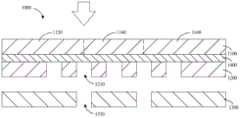
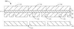
请参考图1,在一般的可折叠的电子设备1000中,其包括依次设置的柔性显示面板1100、背板1200和转轴1300。背板1200设于柔性显示面板1100和转轴1300之间。其中,柔性显示面板1100可例如为OLED(Organic Light-Emitting Diode,有机发光二极管)面板,该柔性显示面板1100可以在外力作用下产生一定程度的弯折,以实现电子设备1000的多角度显示。背板1200可以通过OCA(Optically Clear Adhesive,光学胶)层1400等结构来与柔性显示面板1100固定连接,以支撑和保护柔性显示面板1100。转轴1300则可以位于背板1200的一侧并且远离柔性显示面板1100。Please refer to FIG. 1 , in a general foldable
该转轴1300可以转动,并使转轴1300上的背板1200和柔性显示面板1100同步转动,以使电子设备1000具备展开、折叠等状态。The
为了实现弯折,柔性显示面板1100可以包括第一展开部1120、弯折部1140和第二展开部1160,弯折部1140位于第一展开部1120和第二展开部1160之间。应当理解,该弯折部1140可以使柔性显示面板1100实现柔性弯折的功能。In order to realize bending, the
一些实施例中,电子设备1000可以具有展开状态和折叠状态。其中,对于向内弯折的电子设备,展开状态可以指第一展开部1120和第二展开部1160之间的夹角大于或者等于30°的状态;折叠状态可以指第一展开部1120和第二展开部1160之间的夹角小于30°的状态。对于向外弯折的电子设备,展开状态可以指第一展开部1120和第二展开部1160之间的夹角小于或者等于330°的状态;折叠状态可以指第一展开部1120和第二展开部1160之间的夹角大于330°的状态。应当理解,对于向内弯折或者向外弯折的电子设备,其展开状态均可以包括第一展开部1120和第二展开部1160之间的夹角等于或者约等于180°。应当理解,在误差许可范围内,上述示例出的夹角数值可以存在一定的偏差,而不必然限定在精准的夹角数值内。In some embodiments, the
例如:在展开状态为180°的情况下,电子设备1000可以向内折叠,并使柔性显示面板1100的第一展开部1120和第二展开部1160之间形成90°、100°、110°或者120°等小于180°的夹角。又例如:电子设备1000可以向外折叠,并使柔性显示面板1100的第一展开部1120和第二展开部1160之间形成270°、315°、330°或者360°等大于180°的夹角。For example: in the case that the unfolded state is 180°, the
在其他的一些实施例中,电子设备1000的展开状态和折叠状态可以根据实际使用需求而有所调整,对此不加限制。例如:对于向内折叠的电子设备1000,其展开状态也可以指第一展开部1120和第二展开部1160之间的夹角大于或者等于45°等。In some other embodiments, the unfolded state and the folded state of the
应当理解的是,虽然术语“第一展开部”、“第二展开部”等在本文中用来描述柔性显示面板的各个部分,但是这些展开部不应当被这些术语限定。这些术语只是用来将一个展开部与另一展开部区分开。例如,第一展开部可以被命名为第二展开部,并且类似地,第二展开部也可以被命名为第一展开部,而不背离本申请的范围。第一展开部和第二展开部二者都是展开部,但是它们可以不是同一展开部,在某些场景下也可以是同一展开部。It should be understood that although the terms "first unfolded part", "second unfolded part" and the like are used herein to describe various parts of the flexible display panel, these unfolded parts should not be limited by these terms. These terms are only used to distinguish one deployment from another. For example, a first deployment could be termed a second deployment, and, similarly, a second deployment could be termed a first deployment, without departing from the scope of the present application. Both the first expansion part and the second expansion part are expansion parts, but they may not be the same expansion part, and may be the same expansion part in some scenarios.
如上所述,基于可弯折的柔性显示面板1100或者电子设备1000的使用特性,其背板1200在实现支撑、保护柔性显示面板1100的功能的同时,还需要具备一定的弯折力。该弯折力可以指柔性显示面板1100产生形变所需要的作用力。而当背板1200为单层板时,例如背板1200为单层的金属背板1200,根据背板1200的材料特性,该背板1200的弯折力一般会较大。由此导致使用该背板1200的电子设备1000不容易被弯折,从而影响电子设备1000的折叠性能以及折叠寿命。As mentioned above, based on the usage characteristics of the bendable
如图1所示例,为了使背板1200具有相对合适的弯折力,电子设备1000的背板1200可以在其中部开设多个通孔1210。在位置上,该多个通孔1210在柔性显示面板1100上投影可以位于柔性显示面板1100的弯折部1140内;基于此,可以降低背板1200的刚度,以相应降低背板1200的弯折力并满足电子设备1000的弯折需求。As shown in FIG. 1 , in order to make the
但是,由于背板1200是设置在柔性显示面板1100和转轴1300之间,此种开通孔1210的方式也使得柔性显示面板1100的抗挤压力较差。应当理解,在对应通孔1210的区域,柔性显示面板1100可以与转轴1300相连通,相应导致柔性显示面板1100在该对应通孔1210的区域的支撑力较差,也使得背板1200的抗挤压力较差。转轴1300的表面也会存在一些缝隙1310。当背板1200的通孔1210在柔性显示面板1100上的投影与转轴1300的缝隙1310在柔性显示面板1100上的投影至少部分重叠时,柔性显示面板1100在对应通孔1210的区域的支撑力则会更差。随着电子设备1000弯折次数的增加或者用户点击柔性显示面板1100的次数的增加,柔性显示面板1100则更容易出现碎亮点、黑斑、坏点等显示缺陷,进而降低电子设备1000的使用寿命。However, since the
举例说明,在用户在点击柔性显示面板1100以实现触控操作的过程中,由于柔性显示面板1100之对应通孔1210和缝隙1310的区域一般是对应到柔性显示面板1100的中部,用户手指的指甲很容易接触到该区域。如图1的箭头所示,该区域的柔性显示面板1100直接对应到连通的通孔1210和缝隙1310,其并没有得到良好支撑;可以预见地,随着用户点击次数的增加,用户的手指及指甲也会更频繁地挤压该区域的柔性显示面板1100,并使柔性显示面板1100出现碎亮点、黑斑或者坏点等显示缺陷。For example, when the user clicks the
此外,以柔性显示面板1100和背板1200之间通过OCA层1400实现固定连接为例,随着电子设备1000折叠次数的增加,OCA层1400也可能部分挤入到背板1200的通孔1210内。相应的,柔性显示面板1100在呈现画面时出现部分变形的光影反射变化,由此出现横纹等显示缺陷。In addition, taking the fixed connection between the
针对上面一般可折叠的电子设备1000所存在各种问题,本申请以下实施例提供了一种电子设备,该电子设备通过对背板的结构进行改造,使得该背板可以兼顾弯折性能和抗挤压性能,以避免柔性显示面板出现碎亮点、黑斑、坏点、横纹等显示缺陷,由此可以提高使用该背板的电子设备的使用寿命。此外,背板之朝向柔性显示面板的一侧并没有开孔或者开孔的总面积较小,由此可以提高背板的抗挤压性能。基于此,可以在一定程度上防止OCA层挤入背板,以避免柔性显示面板出现横纹等显示缺陷,以提高电子设备的使用寿命。。In view of the various problems of the above-mentioned general foldable
应当理解,本申请各实施例提供的电子设备可例如为手机、平板电脑、笔记本电脑或者穿戴式显示设备等,对此不加限制。It should be understood that the electronic device provided by each embodiment of the present application may be, for example, a mobile phone, a tablet computer, a notebook computer, or a wearable display device, etc., without limitation.
在其他的一些实施例中,该电子设备也可例如为车载显示器。基于此,可以在需要提供显示时展开该车载显示器,并且在不需要提供显示时折叠该车载显示器。In some other embodiments, the electronic device may also be, for example, a vehicle display. Based on this, the vehicle-mounted display can be unfolded when a display needs to be provided, and the vehicle-mounted display can be folded when no display is required to be provided.
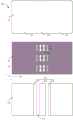
为了便于理解,各实施例主要是以电子设备在展开状态为180°来举例说明。如图2所示例的,将电子设备100a的宽度方向定义为第一方向X,将电子设备100a的长度方向定义为第二方向Y,第一方向X与第二方向Y相垂直。For ease of understanding, each embodiment is mainly illustrated by taking the electronic device in an unfolded state at 180° as an example. As shown in FIG. 2 , the width direction of the
举例说明,对于矩形的电子设备100a,其宽度方向或者第一方向X一般是指数值较小的边长的延伸方向;但在一些情况中,根据实际需求,矩形的电子设备100a的第一方向X也可以指数值较大或者较小的边长的延伸方向。例如:电子设备100a为挂墙式的电子设备,其不怎么需要考虑到便携性并且具有较大的面板尺寸,因此该电子设备100a的第一方向X可以根据需求而定,对此不加限制。For example, for a rectangular
请同步参考图2和图3,一些实施例中,电子设备100a的转轴130可以包括第一支撑板132、第二支撑板134和第三支撑板136。该第一支撑板132设置于第二支撑板134和第三支撑板136之间,第二支撑板134和第三支撑板136均与第一支撑板132转动连接。在外力作用下,第二支撑板134和第三支撑板136可以相对第一支撑板132转动,由此可以使电子设备100a具备可折叠的功能。应当理解,为了实现转动,在第一支撑板132与第二支撑板134之间、第一支撑板132与第三支撑板136之间均可能存在缝隙131。此外,在第一支撑板132、第二支撑板134或者第三支撑板136的表面也可能存在缝隙131。Please refer to FIG. 2 and FIG. 3 simultaneously. In some embodiments, the
一些实施例中,电子设备100a还可以包括中框150,该中框与转轴130固定连接或者可拆卸连接。应当理解,该中框150可以支撑柔性显示面板110,并且可以跟随转轴130的转动而同步转动。In some embodiments, the
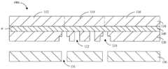
与上述一般的电子设备1000不同,本申请实施例提供的电子设备100a的背板120开设有第一盲孔121,该第一盲孔121位于背板120的一侧并且远离柔性显示面板110。以柔性显示面板110的表面作为参照面P,该第一盲孔121在参照面P上的投影与转轴130的缝隙131在参照面P上的投影至少部分重叠。其中,该柔性显示面板110的表面可以指柔性显示面板110的出光面,也可以指柔性显示面板110的背光面。该出光面和该背光面为柔性显示面板110相背的两个面,并且出光面可以供光线出射以呈现对应画面。为便于理解,各实施例中主要以柔性显示面板110的背光面作为参照面P来举例说明。Different from the above-mentioned general
一些实施例中,相较于上述的开设通孔1210的背板1200,该第一盲孔121是开设在背板120之朝向转轴130的一侧,其并没有贯穿至背板120之朝向柔性显示面板110的一侧。应当理解,相对于上述开设通孔1210的背板1200,该开设第一盲孔121的背板120可以具有较大的刚度,以保有较大的弯折力和抗挤压力。In some embodiments, compared with the above-mentioned
在其他的一些实施例中,以柔性显示面板110的表面作为参照面P,该第一盲孔121在参照面P上的投影可以覆盖转轴130的缝隙131在参照面P上的投影;或者,该转轴130的缝隙131在参照面P上的投影可以覆盖第一盲孔121在参照面P上的投影。In some other embodiments, the surface of the
请参考图3,一些实施例中,该第一盲孔121的深度d1可以小于或者等于195μm;该背板120的厚度d2可以为30μm~200μm。应当理解,背板120越薄,第一盲孔121的深度越大,则背板120的弯折力也会越小;反之则反。由此,通过对第一盲孔121的形状和深度、背板120的厚度等的调整,可以适应性调整背板120的弯折力,以便于应用到电子设备100a中。Please refer to FIG. 3 , in some embodiments, the depth d1 of the first
请参考图3,一些实施例中,该第一盲孔121的深度d1可例如为10μm、20μm、30μm、40μm、50μm、60μm、70μm、80μm、90μm、100μm、110μm、120μm、130μm、140μm、150μm、160μm、170μm、180μm或者190μm等。Please refer to FIG. 3 , in some embodiments, the depth d1 of the first
请参考图3,一些实施例中,该背板120的厚度d2可例如为30μm、40μm、50μm、60μm、70μm、80μm、90μm、100μm、110μm、120μm、130μm、140μm、150μm、160μm、170μm、180μm、190μm、195μm或者200μm等。其中,厚度d2大于深度d1。Please refer to FIG. 3 , in some embodiments, the thickness d2 of the
请参考图3,一些实施例中,背板120之对应第一盲孔121的区域的厚度d3可以大于或者等于5μm,并且小于200μm;其中,d1+d3=d2。d3可例如为5μm、10μm、20μm、30μm、40μm、50μm、60μm、70μm、80μm、90μm、100μm、110μm、120μm、130μm、140μm、150μm、160μm、170μm、180μm、190μm或者195μm等。Referring to FIG. 3 , in some embodiments, the thickness d3 of the region of the
请参考图3,一些实施例中,相邻第一盲孔121之间的距离e1可以为5μm~100μm。基于此,通过对第一盲孔之间的距离的调整,同样可以适应性调整背板的弯折力,以便于应用到电子设备中。Please refer to FIG. 3 , in some embodiments, the distance e1 between adjacent first
一些实施例中,该距离e1可例如为5μm、10μm、20μm、30μm、40μm、50μm、60μm、70μm、80μm、90μm或者100μm等。In some embodiments, the distance e1 may be, for example, 5 μm, 10 μm, 20 μm, 30 μm, 40 μm, 50 μm, 60 μm, 70 μm, 80 μm, 90 μm or 100 μm.
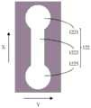
请同步参考图2至图4,一些实施例中,沿着背板120的第一方向X,第一盲孔121可以包括依次连通的第一环形区1211、第一连接区1213和第二环形区1215。而沿着背板120的第二方向Y,该第一环形区1211和第二环形区1215的尺寸均大于第一连接区1213的尺寸;基于此,该第一环形区1211和第二环形区1215可以释放背板120的内应力,该第一连接区1213则可以降低第一盲孔121在整体上的开孔面积,以提高背板120的抗挤压力。Please refer to FIG. 2 to FIG. 4 synchronously. In some embodiments, along the first direction X of the
在一些实施例中,第一环形区1211和第二环形区1215的形状相同。如图4所示例的,第一环形区1211和第二环形区1215均为圆形,第一连接区1213为矩形,该第一盲孔121在整体上的形状为哑铃形。In some embodiments, the first
在其他的一些实施例中,第一环形区1211和第二环形区1215的形状也可以不同,对此不加限制。例如:第一环形区1211和第二环形区1215均为圆形,并且第一环形区1211的直径大于第二环形区1215的直径等。In some other embodiments, the shapes of the first
一些实施例中,对应转轴130的每一缝隙131,可以在背板120上开设一个、两个或者多个第一盲孔121,对此不加限制。In some embodiments, corresponding to each
在其他的一些实施例中,对应转轴130的每一缝隙131,第一盲孔121的数量在15个、20个或者25个以内,该些第一盲孔121可以沿着第一方向X依次设置。In some other embodiments, corresponding to each
一些实施例中,沿着第二方向Y,可以在背板120上开设多列第一盲孔121,以使背板120具有合适的弯折性能和抗挤压性能。In some embodiments, along the second direction Y, multiple rows of first
如图2所示例的,对应转轴130的一个缝隙131,第一盲孔121的数量为三个,该三个第一盲孔121沿着第一方向X间隔设置。请参考图5,在其他的一些实施例中,对应转轴130之间的一个缝隙131,第一盲孔121的数量也可以是一个,该一个第一盲孔121沿着第一方向X延伸,以适应性降低背板120的弯折力。As shown in FIG. 2 , corresponding to one
一些实施例中,第一盲孔121的形状可以包括圆形、矩形、长条形、椭圆形等形状中的至少一种。以第一盲孔121为例,如图6所示例的,第一盲孔121的形状可以是椭圆形和矩形的复合形状;或者,如图7所示例的,第一盲孔121的形状也可以是椭圆和长条形的复合形状,对此不加限制。In some embodiments, the shape of the first
请参考图8,在其他的一些实施例中,第一盲孔121还可以延伸至背板120的边缘;其中,第一盲孔121的延伸方向与电子设备100a的第一方向X相同。Please refer to FIG. 8 , in some other embodiments, the first
请同步参考图9和图10,本申请还提供了一种电子设备100b,相对于上述的电子设备100a,第一支撑板132可以包括主体部1322和转动部1324;该转动部1324位于主体部1322的一侧,并且朝向远离主体部1322的方向延伸。如图9所示例的,该转动部1324的数量为两个,并且可以用于实现第一支撑板132与第二支撑板134等结构之间的转动连接。Please refer to FIG. 9 and FIG. 10 synchronously. The present application also provides an
一些实施例中,对应第一支撑板132的转动部1324,第二支撑板134形成有容置部1342,该容置部1342可以容置转动部1324,以便于实现第一支撑板132和第二支撑板134之间的转动连接。In some embodiments, corresponding to the
应当理解,根据第一支撑板132的转动部1324与第二支撑板134的容置部1342等结构之间的连接关系,第一支撑板132和第二支撑板134之间会形成特定走向的缝隙131,可以根据该缝隙131的走向,在背板120的对应位置上开设第一盲孔121。如图10所示例的,以柔性显示面板110的表面作为参照面P,第一盲孔121在参照面P上的投影,其可以覆盖第一支撑板132的转动部1324在参照面P上的投影。It should be understood that, according to the connection relationship between the
一些实施例中,第三支撑板136与第一支撑板132之间的关系可类比于第二支撑板134与第一支撑板132之间的关系进行理解,对此不加赘述。In some embodiments, the relationship between the
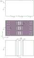
请同步参考图11和图12,本申请实施例还提供了一种电子设备100c,相对于上述实施例所提供的电子设备(100a,100b),该电子设备100c的背板120还开设了第一通孔122。该第一通孔122与第一盲孔121间隔设置,并且与柔性显示面板110的弯折部1140相对应,以进一步降低背板120的弯折力。以柔性显示面板110的表面作为参照面P,该第一通孔122在参照面P的投影与缝隙131在参照面P上的投影相间隔;换而言之,转轴130在参照面P上的投影可以覆盖该第一通孔122在参照面P上的投影。Please refer to FIG. 11 and FIG. 12 synchronously. The embodiment of the present application also provides an
应当理解,相对于一般的电子设备1000的背板1200,本申请实施例提供的背板120的第一通孔122的总面积较小。基于此,当用户按压柔性显示面板110之对应第一通孔122的区域时,可以通过转轴130来对柔性显示面板110提供一定的支撑力,以避免柔性显示面板110出现碎亮点、黑斑、坏点等显示缺陷,以提高电子设备的使用寿命。It should be understood that, compared with the
此外,基于第一盲孔121和第一通孔122的配合,背板120在朝向柔性显示面板110的一侧的总开孔面积较小,即背板120之朝向柔性显示面板110的一面相对平整,因此还可以在一定程度上防止OCA层140挤入背板120,以避免电子设备100c出现横纹等显示缺陷。In addition, based on the cooperation between the first
一些实施例中,该第一通孔122的形状可以与第一盲孔121的形状相同;或者,如上述对第一盲孔121形状的描述,该第一通孔122的形状也可以包括圆形、矩形、长条形、椭圆形等形状中的至少一种,对此不加限制。In some embodiments, the shape of the first through
如图13所示例的,类似第一盲孔121,该第一通孔122可以包括依次相连的第三环形区1221、第二连接区1223和第四环形区1225。沿着背板120的第二方向Y,该第三环形区1221和第四环形区1225的尺寸均大于第二连接区1223的尺寸。在电子设备100c弯折的过程中,该第三环形区1221和第四环形区1225可以释放背板120的内应力,以降低背板120的弯折力。该第二连接区1223则可以降低第一通孔122在整体上的开孔面积,以在一定程度上防止OCA层140挤入背板120,由此可以避免电子设备100c出现横纹等显示缺陷,以提高电子设备的使用寿命。As shown in FIG. 13 , similar to the first
请再参考图12,一些实施例中,相邻的第一盲孔121和第一通孔122之间的距离e2可以为5μm~100μm。基于此,通过对第一盲孔121和第一通孔122之间的距离的调整,同样可以适应性调整背板120的弯折力,以便于应用到电子设备中。Please refer to FIG. 12 again. In some embodiments, the distance e2 between adjacent first
一些实施例中,该距离e2可例如为5μm、10μm、20μm、30μm、40μm、50μm、60μm、70μm、80μm、90μm或者100μm等。In some embodiments, the distance e2 may be, for example, 5 μm, 10 μm, 20 μm, 30 μm, 40 μm, 50 μm, 60 μm, 70 μm, 80 μm, 90 μm or 100 μm.
相对于一般开设通孔1210的背板1200,上述实施例提供的开设第一盲孔121和第一通孔122的背板120,其抗挤压力大约可以提升3kgf~5kgf(kilogram-force,千克力),以更好地保护柔性显示面板110,以延长电子设备100c的使用寿命。Compared with the
请同步参考图14和图15,由于背板120的厚度较大、重量可能也较大,对此在本申请实施例提供的电子设备100d中,还可以在背板120上开设第二盲孔123,该第二盲孔123开设于背板120的一侧并且朝向转轴130。而与上述的第一盲孔121不同,以柔性显示面板110作为参照面P,该第二盲孔123在参照面P上的投影位于柔性显示面板110的展开部(112,116)。应当理解,通过该第二盲孔123可以降低背板120的重量,以实现电子设备100c的轻化,以提高电子设备100c的可携带性。Please refer to FIG. 14 and FIG. 15 simultaneously. Since the
一些实施例中,该第二盲孔123的形状可以与第一盲孔121的形状相同。例如;第二盲孔123和第一盲孔121的形状、深度等参数均一致。In some embodiments, the second
在其他的一些实施例中,该第二盲孔123的形状可以包括圆形、矩形、长条形、椭圆形等形状中的至少一种,并不强制要求与第一盲孔121一致,对此不加限制。应当理解,第一盲孔121和第二盲孔123可以设计成具有不同的形状、深度和截面形状,以对应满足电子设备100c的弯折、抗挤压、冲击可靠性等需求。In some other embodiments, the shape of the second
请同步参考图16和图17,相对于上述各实施例中的电子设备(100a~100d),本申请实施例还提供了另一种电子设备100e,该电子设备100e是将第一盲孔121调整成第二通孔124。与一般背板1200的通孔1210不同,沿着柔性显示面板110到转轴130的方向,该第二通孔124具有相对的第一孔径w1和第二孔径w2,并且第一孔径w1小于第二孔径w2。基于此,相对于第一盲孔121,该第二通孔124可以进一步减小背板120弯折时的局部应力,以便于背板120弯折。Please refer to FIG. 16 and FIG. 17 synchronously. Compared with the electronic devices (100a-100d) in the above-mentioned embodiments, this embodiment of the present application also provides another
从制造工艺来看,此第二通孔124的结构也可以理解为在第一盲孔121的孔底开设通孔,以进一步降低背板120弯折时的局部应力。例如:在第一盲孔121的基础上进行再次的曝光、显影、刻蚀等操作,以形成第二通孔124。From the perspective of manufacturing process, the structure of the second through
一些实施例中,第二通孔124的第一孔径w1小于或者等于300μm(即0.3mm);第二孔径w2的大小则可以根据背板120的弯折力、抗挤压力等而适应性调整,对此不加限制。In some embodiments, the first aperture w1 of the second through
一些实施例中,该第二通孔124的第一孔径w1可例如为10μm、20μm、30μm、40μm、50μm、60μm、70μm、80μm、90μm、100μm、120μm、140μm、160μm、180μm、200μm、220μm、240μm、260μm或者280μm等。In some embodiments, the first aperture w1 of the second through
应当理解,用户手指的指甲200的厚度f1一般为0.3mm~0.8mm,该数值一般是大于第二通孔124的第一孔径w1。基于此,当用户进行触控操作时,即使用户手指的指甲接触到柔性显示面板110之对应第二通孔124的区域,背板120仍可以对柔性显示面板110提供一定的支撑力,以避免柔性显示面板110出现碎亮点、黑斑、坏点等显示缺陷,并提高电子设备100e的使用寿命。It should be understood that the thickness f1 of the
一些实施例中,由于第二通孔124的第一孔径w1较小,用户在对电子设备100e进行触控或者折叠的过程中,OCA层140也不容易通过该第二通孔124而挤入背板120,由此可以避免电子设备100e出现横纹等显示缺陷。In some embodiments, since the first aperture w1 of the second through
一些实施例中,以柔性显示面板110的表面作为参照面P,该第二通孔124在参照面P上的投影也可以位于柔性显示面板110的展开部或者弯折部,由此可以降低背板120的重量,以便于适用在电子设备100e中。在其他的一些实施例中,也可以在背板120之对应展开部(112,116)的区域设置上述的第二盲孔123;或者,在背板120之对应展开部(112,116)的区域设置第二通孔124和上述的第二盲孔123,由于背板120的局部厚度减小或者被掏空,由此同样可以降低背板120的重量。In some embodiments, the surface of the
一些实施例中,该背板120可以为金属背板120。例如:该金属背板120可以包括钢、镍、钛、铝或者铜合金等材料;或者,该金属背板120可以包括金属基复合材料(例如Al-SiC)、多层金属复合材料(例如Al-Cu或者SUS-Al-SUS)等,对此不加限制。In some embodiments, the
在其他的一些实施例中,该背板120可以为非金属背板120。例如:该非金属背板120可以包括树脂或者玻璃纤维等材料,对此不加限制。In some other embodiments, the
一些实施例中,通过调整盲孔(121,123)的形状或者孔径、以及调整通孔(122,124)的形状或者孔径,在确保对柔性显示面板110的支撑、保护效果的同时,可以适应性调整该背板120的抗挤压力和弯折力,以满足电子设备100e的弯折需求。In some embodiments, by adjusting the shape or diameter of the blind holes (121, 123) and the shape or diameter of the through holes (122, 124), while ensuring the support and protection effects on the
应当理解,各附图中的盲孔(121,123)、通孔(122,124)的数量和大小作为示例,在实际应用中,盲孔(121,123)、通孔(122,124)的数量和大小可以根据实际需求而有所调整,对此不加限制。It should be understood that the number and size of the blind holes (121, 123) and through holes (122, 124) in the drawings are examples. In practical applications, the blind holes (121, 123), through holes (122, 124) The number and size can be adjusted according to actual needs, without limitation.
请参考图18,为了在背板120上形成盲孔(121,123)和通孔(122,124),本申请实施例还提供了一种背板120的加工方法,该方法包括但不限于以下步骤:Please refer to FIG. 18. In order to form blind holes (121, 123) and through holes (122, 124) on the
S101:在板材的两侧涂覆油墨层。S101: Coating an ink layer on both sides of the plate.
应当理解,该板材可以是金属板材或者非金属板材等;油墨层的涂覆方式可例如为喷涂丝印或者移印,对此不加限制。It should be understood that the plate may be a metal plate or a non-metal plate, etc.; the coating method of the ink layer may be, for example, spray silk screen printing or pad printing, which is not limited.
S102:在板材的两侧涂覆菲林层。S102: Coating film layers on both sides of the plate.
其中,菲林层涂覆于油墨层上并且远离板材。相应的,在板材的两侧均涂覆有油墨层和菲林层。Wherein, the film layer is coated on the ink layer and kept away from the plate. Correspondingly, an ink layer and a film layer are coated on both sides of the plate.
S103:对板材进行曝光,以在菲林层上形成第一刻蚀图案。S103: exposing the board to form a first etching pattern on the film layer.
其中,板材的两侧各有一层菲林层,该两层菲林层的第一刻蚀图案不同,以使板材在后续加工流程可以对应形成盲孔(121,123)、通孔(122,124)。Wherein, there is a film layer on both sides of the board, and the first etching patterns of the two film layers are different, so that blind holes (121, 123) and through holes (122, 124) can be formed correspondingly in the subsequent processing of the board. .
S104:去除菲林层,以在油墨层上形成第二刻蚀图案。S104: removing the film layer to form a second etching pattern on the ink layer.
应当理解,基于第一刻蚀图案,还可以去除油墨层的部分油墨,由此形成第二刻蚀图案。以对于位于板材同侧的菲林层和油墨层,对应的第一刻蚀图案和第二刻蚀图案相同。It should be understood that based on the first etching pattern, part of the ink of the ink layer may also be removed, thereby forming the second etching pattern. For the film layer and the ink layer on the same side of the plate, the corresponding first etching pattern and the second etching pattern are the same.
S105:对板材进行刻蚀并去除油墨层,以在板材上形成盲孔、通孔。S105: Etching the board and removing the ink layer, so as to form blind holes and through holes on the board.
一些实施例中,步骤S105之后的板材具有较大的尺寸,因此可以通过对该板材进行切割,以形成一个、两个或者多个背板120。In some embodiments, the plate after step S105 has a larger size, so the plate can be cut to form one, two or more
在其他的一些实施例中,步骤S105之后的板材具有与背板120相同的尺寸,该板材即可以作为背板120。In some other embodiments, the board after step S105 has the same size as the
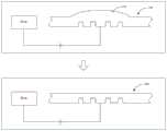
如上各实施例中所述的电子设备(100a~100e),其背板120可以由金属板材所形成的金属背板120。而由于金属板材一般是通过轧制工艺成型;对应此类型的工艺,该金属板材的表面会存在拉应力。在经过上述的刻蚀过程后,金属板材中被刻蚀的一面会释放内应力,但是金属板材中没有被刻蚀或者刻蚀较少的一面仍保留有较大的内应力,由此导致最终形成的金属背板120可能存在起拱部分125。该起拱部分125会影响背板120的弯折和抗挤压等性能,不利于将背板120应用到电子设备100e中。For the electronic devices ( 100 a - 100 e ) described in the above embodiments, the
对此,请参考图19,一些实施例中,上述的加工方法还可以包括以下步骤:对背板的起拱部分125进行局部退火,退火温度为0.5Tb;其中,Tb为金属再结晶温度。For this, please refer to FIG. 19 , in some embodiments, the above-mentioned processing method may further include the following steps: performing local annealing on the
应当理解,基于上述的S201步骤,可以在背板120的起拱部分125放置局部加热装置,以进行局部退火。该局部加热装置可例如为区熔炉,由此可以有效地释放背板120的内应力,以消除背板120的起拱部分125。It should be understood that, based on the above step S201, a local heating device may be placed on the
请参考图20,在其他的一些实施例中,与上述进行局部退火的方式不同,加工方法还可以包括以下步骤:以不锈钢电极作为阴极、背板120作为阳极,将背板120放入电解液中进行电解;其中,该电解液包括高氯酸和乙酸,高氯酸:乙酸=1:15。Please refer to FIG. 20 , in some other embodiments, different from the above-mentioned local annealing method, the processing method may also include the following steps: using the stainless steel electrode as the cathode and the
由于背板120的起拱部分125与电解液的接触面积更大,反应速度大于背板120的其他区域,因此可以通过反应来消除背板120的起拱部分125。Since the
Claims (14)
Priority Applications (3)
| Application Number | Priority Date | Filing Date | Title |
|---|---|---|---|
| CN202111347109.9ACN116129736A (en) | 2021-11-15 | 2021-11-15 | Electronic equipment |
| EP22891742.3AEP4401066A4 (en) | 2021-11-15 | 2022-10-17 | ELECTRONIC DEVICE |
| PCT/CN2022/125599WO2023082945A1 (en) | 2021-11-15 | 2022-10-17 | Electronic device |
Applications Claiming Priority (1)
| Application Number | Priority Date | Filing Date | Title |
|---|---|---|---|
| CN202111347109.9ACN116129736A (en) | 2021-11-15 | 2021-11-15 | Electronic equipment |
Publications (1)
| Publication Number | Publication Date |
|---|---|
| CN116129736Atrue CN116129736A (en) | 2023-05-16 |
Family
ID=86296010
Family Applications (1)
| Application Number | Title | Priority Date | Filing Date |
|---|---|---|---|
| CN202111347109.9APendingCN116129736A (en) | 2021-11-15 | 2021-11-15 | Electronic equipment |
Country Status (3)
| Country | Link |
|---|---|
| EP (1) | EP4401066A4 (en) |
| CN (1) | CN116129736A (en) |
| WO (1) | WO2023082945A1 (en) |
Citations (13)
| Publication number | Priority date | Publication date | Assignee | Title |
|---|---|---|---|---|
| CN107564417A (en)* | 2017-10-20 | 2018-01-09 | 武汉华星光电半导体显示技术有限公司 | Flexible display panels backboard and flexible display |
| CN109727538A (en)* | 2017-10-31 | 2019-05-07 | 乐金显示有限公司 | Rollable display |
| CN110062077A (en)* | 2019-02-01 | 2019-07-26 | 华为终端有限公司 | Folding terminal device support chip and folding terminal device |
| CN211455156U (en)* | 2020-01-22 | 2020-09-08 | 华为技术有限公司 | Display module and electronic equipment |
| CN111862824A (en)* | 2020-08-27 | 2020-10-30 | 京东方科技集团股份有限公司 | Display components and display devices |
| CN112289750A (en)* | 2020-10-28 | 2021-01-29 | 武汉华星光电半导体显示技术有限公司 | Supporting layer and flexible display panel |
| CN112435578A (en)* | 2020-11-23 | 2021-03-02 | 京东方科技集团股份有限公司 | Panel supporting structure, manufacturing method thereof and display device |
| CN112509462A (en)* | 2020-09-29 | 2021-03-16 | 联想(北京)有限公司 | Flexible display screen assembly and electronic equipment |
| CN112991948A (en)* | 2021-02-23 | 2021-06-18 | 京东方科技集团股份有限公司 | Support piece and display device |
| CN113202857A (en)* | 2021-07-05 | 2021-08-03 | 武汉华星光电半导体显示技术有限公司 | Hinge, flexible display panel and electronic device |
| CN113362712A (en)* | 2021-06-15 | 2021-09-07 | 武汉华星光电半导体显示技术有限公司 | Flexible display module |
| CN113450646A (en)* | 2021-03-04 | 2021-09-28 | 京东方科技集团股份有限公司 | Folding display device and electronic equipment |
| CN214476073U (en)* | 2020-12-01 | 2021-10-22 | 京东方科技集团股份有限公司 | Flexible display module and foldable display device |
Family Cites Families (11)
| Publication number | Priority date | Publication date | Assignee | Title |
|---|---|---|---|---|
| KR102647358B1 (en)* | 2018-09-12 | 2024-03-12 | 엘지디스플레이 주식회사 | Display device |
| CN109830185B (en)* | 2019-02-22 | 2024-05-17 | 华为技术有限公司 | Folding component and folding display terminal |
| KR20210145203A (en)* | 2019-04-02 | 2021-12-01 | 센셀, 인크. | Perforated support layer to facilitate static and dynamic bending |
| KR102760756B1 (en)* | 2019-05-15 | 2025-02-03 | 삼성전자주식회사 | Foldable electronic device |
| CN118015925A (en)* | 2019-07-29 | 2024-05-10 | Lg伊诺特有限公司 | Display substrate and display device including the same |
| CN110649058B (en)* | 2019-09-27 | 2022-11-04 | 京东方科技集团股份有限公司 | A flexible display module and flexible display device |
| CN118280219A (en)* | 2019-11-28 | 2024-07-02 | 京东方科技集团股份有限公司 | Foldable support piece, preparation method and display device |
| CN115988114B (en)* | 2019-12-27 | 2024-11-15 | 华为技术有限公司 | Flexible screen and foldable equipment |
| WO2021129882A1 (en)* | 2019-12-27 | 2021-07-01 | 华为技术有限公司 | Electronic device |
| CN111508370B (en)* | 2020-05-19 | 2023-01-24 | 武汉华星光电半导体显示技术有限公司 | Foldable display device |
| CN111911525B (en)* | 2020-08-17 | 2024-12-27 | 京东方科技集团股份有限公司 | Support device and foldable device |
- 2021
- 2021-11-15CNCN202111347109.9Apatent/CN116129736A/enactivePending
- 2022
- 2022-10-17EPEP22891742.3Apatent/EP4401066A4/enactivePending
- 2022-10-17WOPCT/CN2022/125599patent/WO2023082945A1/ennot_activeCeased
Patent Citations (13)
| Publication number | Priority date | Publication date | Assignee | Title |
|---|---|---|---|---|
| CN107564417A (en)* | 2017-10-20 | 2018-01-09 | 武汉华星光电半导体显示技术有限公司 | Flexible display panels backboard and flexible display |
| CN109727538A (en)* | 2017-10-31 | 2019-05-07 | 乐金显示有限公司 | Rollable display |
| CN110062077A (en)* | 2019-02-01 | 2019-07-26 | 华为终端有限公司 | Folding terminal device support chip and folding terminal device |
| CN211455156U (en)* | 2020-01-22 | 2020-09-08 | 华为技术有限公司 | Display module and electronic equipment |
| CN111862824A (en)* | 2020-08-27 | 2020-10-30 | 京东方科技集团股份有限公司 | Display components and display devices |
| CN112509462A (en)* | 2020-09-29 | 2021-03-16 | 联想(北京)有限公司 | Flexible display screen assembly and electronic equipment |
| CN112289750A (en)* | 2020-10-28 | 2021-01-29 | 武汉华星光电半导体显示技术有限公司 | Supporting layer and flexible display panel |
| CN112435578A (en)* | 2020-11-23 | 2021-03-02 | 京东方科技集团股份有限公司 | Panel supporting structure, manufacturing method thereof and display device |
| CN214476073U (en)* | 2020-12-01 | 2021-10-22 | 京东方科技集团股份有限公司 | Flexible display module and foldable display device |
| CN112991948A (en)* | 2021-02-23 | 2021-06-18 | 京东方科技集团股份有限公司 | Support piece and display device |
| CN113450646A (en)* | 2021-03-04 | 2021-09-28 | 京东方科技集团股份有限公司 | Folding display device and electronic equipment |
| CN113362712A (en)* | 2021-06-15 | 2021-09-07 | 武汉华星光电半导体显示技术有限公司 | Flexible display module |
| CN113202857A (en)* | 2021-07-05 | 2021-08-03 | 武汉华星光电半导体显示技术有限公司 | Hinge, flexible display panel and electronic device |
Also Published As
| Publication number | Publication date |
|---|---|
| EP4401066A4 (en) | 2025-01-15 |
| EP4401066A1 (en) | 2024-07-17 |
| WO2023082945A1 (en) | 2023-05-19 |
Similar Documents
| Publication | Publication Date | Title |
|---|---|---|
| CN110649058B (en) | A flexible display module and flexible display device | |
| CN211455156U (en) | Display module and electronic equipment | |
| US10833132B2 (en) | Hard coat-attached film type touch sensor and flexible device using same | |
| US20230154360A1 (en) | Display panel and flexible display device | |
| US20230157131A1 (en) | Flexible display panel and flexible display device | |
| US20210083210A1 (en) | Flexible element, flexible display device and manufacturing method thereof | |
| CN104412211B (en) | Electrostatic capacitive touch panel, manufacturing method thereof, and input device | |
| WO2020083104A1 (en) | Display module, electronic device, and method for manufacturing display module | |
| EP4086883A1 (en) | Foldable display apparatus and manufacturing method therefor | |
| CN108962030A (en) | Flexible display screen, preparation method and display device | |
| CN217181742U (en) | A display screen and electronic equipment | |
| CN1549962A (en) | Removable transparent touch panel mounting structure and mounting sheet used in same | |
| WO2023108750A1 (en) | Display module and electronic device | |
| CN109407869A (en) | Touch-control structure and preparation method thereof, display device | |
| JP2013084026A (en) | Touch sensor for touch panel | |
| CN111124182A (en) | Flexible screen assembly and flexible screen terminal | |
| CN109637382A (en) | Display panel and display device | |
| CN111785756A (en) | Flexible display panel, preparation method thereof, and display device | |
| CN110875441B (en) | Protective film and manufacturing method thereof, flexible panel and manufacturing method thereof, and display device | |
| WO2023035347A1 (en) | Display panel and manufacturing method therefor, and mobile terminal | |
| TWM499647U (en) | Touch-sensitive device | |
| CN110491914A (en) | Flexible luminescent panel, the preparation method of flexible luminescent panel and display equipment | |
| KR20180060205A (en) | Flexible display supporters for supporting flexible displays and the method for thereof | |
| CN212161817U (en) | Flexible display panel and display device | |
| CN115132088A (en) | Display panel and display device |
Legal Events
| Date | Code | Title | Description |
|---|---|---|---|
| PB01 | Publication | ||
| PB01 | Publication | ||
| SE01 | Entry into force of request for substantive examination | ||
| SE01 | Entry into force of request for substantive examination |