CN116124784A - Membrane electrode perforation defect and coating uniformity integrated detection device - Google Patents
Membrane electrode perforation defect and coating uniformity integrated detection deviceDownload PDFInfo
- Publication number
- CN116124784A CN116124784ACN202211394237.3ACN202211394237ACN116124784ACN 116124784 ACN116124784 ACN 116124784ACN 202211394237 ACN202211394237 ACN 202211394237ACN 116124784 ACN116124784 ACN 116124784A
- Authority
- CN
- China
- Prior art keywords
- fixed
- membrane electrode
- box
- detection
- fixedly connected
- Prior art date
- Legal status (The legal status is an assumption and is not a legal conclusion. Google has not performed a legal analysis and makes no representation as to the accuracy of the status listed.)
- Pending
Links
Images


Classifications
- G—PHYSICS
- G01—MEASURING; TESTING
- G01N—INVESTIGATING OR ANALYSING MATERIALS BY DETERMINING THEIR CHEMICAL OR PHYSICAL PROPERTIES
- G01N21/00—Investigating or analysing materials by the use of optical means, i.e. using sub-millimetre waves, infrared, visible or ultraviolet light
- G01N21/84—Systems specially adapted for particular applications
- G01N21/88—Investigating the presence of flaws or contamination
- G—PHYSICS
- G01—MEASURING; TESTING
- G01N—INVESTIGATING OR ANALYSING MATERIALS BY DETERMINING THEIR CHEMICAL OR PHYSICAL PROPERTIES
- G01N21/00—Investigating or analysing materials by the use of optical means, i.e. using sub-millimetre waves, infrared, visible or ultraviolet light
- G01N21/01—Arrangements or apparatus for facilitating the optical investigation
- G—PHYSICS
- G01—MEASURING; TESTING
- G01N—INVESTIGATING OR ANALYSING MATERIALS BY DETERMINING THEIR CHEMICAL OR PHYSICAL PROPERTIES
- G01N27/00—Investigating or analysing materials by the use of electric, electrochemical, or magnetic means
- G01N27/26—Investigating or analysing materials by the use of electric, electrochemical, or magnetic means by investigating electrochemical variables; by using electrolysis or electrophoresis
- G01N27/416—Systems
- G01N27/48—Systems using polarography, i.e. measuring changes in current under a slowly-varying voltage
- Y—GENERAL TAGGING OF NEW TECHNOLOGICAL DEVELOPMENTS; GENERAL TAGGING OF CROSS-SECTIONAL TECHNOLOGIES SPANNING OVER SEVERAL SECTIONS OF THE IPC; TECHNICAL SUBJECTS COVERED BY FORMER USPC CROSS-REFERENCE ART COLLECTIONS [XRACs] AND DIGESTS
- Y02—TECHNOLOGIES OR APPLICATIONS FOR MITIGATION OR ADAPTATION AGAINST CLIMATE CHANGE
- Y02E—REDUCTION OF GREENHOUSE GAS [GHG] EMISSIONS, RELATED TO ENERGY GENERATION, TRANSMISSION OR DISTRIBUTION
- Y02E60/00—Enabling technologies; Technologies with a potential or indirect contribution to GHG emissions mitigation
- Y02E60/30—Hydrogen technology
- Y02E60/50—Fuel cells
Landscapes
- Chemical & Material Sciences (AREA)
- Health & Medical Sciences (AREA)
- Life Sciences & Earth Sciences (AREA)
- General Health & Medical Sciences (AREA)
- Analytical Chemistry (AREA)
- Biochemistry (AREA)
- Physics & Mathematics (AREA)
- General Physics & Mathematics (AREA)
- Immunology (AREA)
- Pathology (AREA)
- Molecular Biology (AREA)
- Chemical Kinetics & Catalysis (AREA)
- Electrochemistry (AREA)
- Investigating Or Analyzing Materials By The Use Of Electric Means (AREA)
Abstract
Translated fromChinese
Description
Translated fromChinese技术领域technical field
本发明涉及膜电极检测技术领域,具体涉及一种膜电极穿孔缺陷及涂层均匀度一体化检测装置。The invention relates to the technical field of membrane electrode detection, in particular to an integrated detection device for membrane electrode perforation defects and coating uniformity.
背景技术Background technique
离子交换膜、催化层、气体扩散层等部件构成了电化学反应的主要场所的部件-膜电极,气体扩散层被广泛使用于燃料电池、PEM电解水装置、二氧化碳还原、氨分解、电化学氢气泵等电化学装置中。通常膜电极中聚合物膜可能在生产中存在针孔、膜局部折皱,其表面催化层涂层可能存在裂纹、条纹、涂覆不均匀等问题。对于气体扩散电极型膜电极,热压装配的过程可能造成气体扩散层中碳管刺穿膜造成针孔、缺陷。Ion exchange membranes, catalytic layers, gas diffusion layers and other components constitute the main part of the electrochemical reaction - the membrane electrode, and the gas diffusion layer is widely used in fuel cells, PEM electrolysis water devices, carbon dioxide reduction, ammonia decomposition, electrochemical hydrogen In electrochemical devices such as pumps. Generally, the polymer membrane in the membrane electrode may have pinholes and local wrinkles during production, and the catalytic layer coating on the surface may have problems such as cracks, streaks, and uneven coating. For the gas diffusion electrode type membrane electrode, the hot press assembly process may cause the carbon tubes in the gas diffusion layer to penetrate the membrane and cause pinholes and defects.
现有的膜电极缺陷诊断通过肉眼检测,将样品置于发光板上用肉眼观察、评判分析表面的缺陷情况的方法相对原始、并且消耗大量的人力以及时间成本,生产效率低下,并且人工检测分辨率低,容易出现漏检,误检等情况的发生;The existing membrane electrode defect diagnosis is through visual inspection. The method of placing the sample on a luminescent plate to observe with the naked eye, judge and analyze the surface defect is relatively primitive, and consumes a lot of manpower and time costs. The production efficiency is low, and manual detection and resolution Low rate, prone to missed detection, false detection and other situations;
现有膜电极的缺陷诊断用激光测距仪测试,通过缺陷位置与标称距离值的偏差≥预设的允差值来确定缺陷,该方法不能排除是否运送过程中有褶皱造成误判断,若底部采用真空吸附保证无褶皱,则降低测试速度,提高时间成本;Existing defect diagnosis of membrane electrodes is tested with a laser rangefinder, and the defect is determined by the deviation between the defect position and the nominal distance value ≥ the preset tolerance value. The bottom adopts vacuum adsorption to ensure no wrinkles, which will reduce the test speed and increase the time cost;
检测微小缺陷时,若检测样品为离子交换膜,其为透明样品,不易观察,需要求探测仪器放大倍数、及快速精准探测,投入成本大且检测时间长,CCM型膜电极其表面为全黑色,不易观察孔洞,需下方放置发光设备,若检测膜电极,膜电极已装配气体扩散层,气体扩散层表面疏松多孔,无法判断缺陷存在与否。When detecting small defects, if the detection sample is an ion-exchange membrane, it is a transparent sample and is not easy to observe. It requires the magnification of the detection instrument and fast and accurate detection. The investment cost is large and the detection time is long. The surface of the CCM type membrane electrode is completely black. , It is not easy to observe the holes, and a light-emitting device needs to be placed below. If the membrane electrode is detected, the membrane electrode has been equipped with a gas diffusion layer. The surface of the gas diffusion layer is loose and porous, and it is impossible to judge whether the defect exists or not.
针对膜电极涂层均匀的检测在实验室级别中主要通过测厚仪,缺点:消耗大量的人力以及时间成本,人工检测分辨率低,容易出现漏检,误检等情况的发生,小型缺陷使用显微镜、扫描电镜、透射电镜等进行观察,缺点:只能单一的识别表面缺陷。The uniform detection of membrane electrode coating is mainly through the thickness gauge at the laboratory level. Disadvantages: consume a lot of manpower and time costs, low resolution of manual detection, prone to missed detection, false detection, etc., small defects use Microscope, scanning electron microscope, transmission electron microscope, etc. for observation. Disadvantage: only a single surface defect can be identified.
发明内容Contents of the invention
为此,本发明提供一种膜电极穿孔缺陷及涂层均匀度一体化检测装置,以解决人为因素可能造成误差,测量范围也较小不能展示真实情况,测试成本较高,探针易将气体扩散层扎漏,样品测试后受到破坏无法继续使用的问题。For this reason, the present invention provides an integrated detection device for membrane electrode perforation defects and coating uniformity to solve possible errors caused by human factors, the measurement range is too small to display the real situation, the test cost is high, and the probe is easy to detect the gas The diffusion layer leaks, and the sample is damaged and cannot be used after the test.
为了实现上述目的,本发明提供如下技术方案:一种膜电极穿孔缺陷及涂层均匀度一体化检测装置,包括箱体,所述箱体内部固定设有支撑板,所述支撑板顶部设有膜电极本体,所述箱体内部设有检测机构;In order to achieve the above object, the present invention provides the following technical solution: an integrated detection device for membrane electrode perforation defects and coating uniformity, including a box body, a support plate is fixed inside the box body, and a support plate is installed on the top of the support plate. Membrane electrode body, the inside of the box is provided with a detection mechanism;
所述检测机构包括两个检测组件,所述检测组件包括两个检测单元,两个所述检测单元分别设于支撑板顶部和底部,所述检测单元包括支撑架,所述支撑架一侧通过轴承连接有绝缘辊,所述支撑架另一侧设有内支撑筒,所述内支撑筒两侧均固定连接有滑动方块,所述支撑架两侧均开设有滑动方槽,两个所述滑动方块分别在两个所述滑动方槽内部滑动连接,所述内支撑筒外部通过轴承套设有导电辊,其中一个所述检测组件的两个检测单元的支撑架两侧均固定连接有固定杆,两个所述固定杆一侧均固定连接有限位块,两个所述限位块一侧均设有连接块,两个所述连接块一侧均开设有开槽,两个所述限位块分别与两个所述开槽相扣合,两个所述连接块一侧均固定设有第二电动推杆,两个所述第二电动推杆均与箱体固定连接。The detection mechanism includes two detection assemblies, the detection assembly includes two detection units, the two detection units are respectively arranged on the top and bottom of the support plate, the detection unit includes a support frame, and one side of the support frame passes through The bearing is connected with an insulating roller, and the other side of the support frame is provided with an inner support cylinder, and both sides of the inner support cylinder are fixedly connected with sliding squares, and both sides of the support frame are provided with sliding square grooves. The sliding blocks are slidingly connected inside the two sliding square grooves, and the inner support cylinder is provided with conductive rollers through bearing sleeves, and the two sides of the support frames of the two detection units of one of the detection components are fixedly connected with fixed rollers. One side of the two fixed rods is fixedly connected with a limit block, one side of the two limit blocks is provided with a connection block, one side of the two connection blocks is provided with a slot, and the two The limiting blocks are engaged with the two slots respectively, and the second electric push rods are fixed on one side of the two connecting blocks, and the two second electric push rods are fixedly connected with the box body.
优选的,所述固定杆外部套设有橡胶卡块,所述固定杆与橡胶卡块相接触,所述橡胶卡块固定嵌设于开槽内部,所述固定杆外部固定套设有齿轮,所述连接块一侧固定设有第三推杆,所述第三推杆输出端固定连接有齿板,所述齿板与齿轮相啮合。Preferably, a rubber block is sheathed on the outside of the fixed rod, the fixed rod is in contact with the rubber block, the rubber block is fixedly embedded in the slot, and a gear is fixed on the outside of the fixed rod. One side of the connection block is fixed with a third push rod, and the output end of the third push rod is fixedly connected with a tooth plate, and the tooth plate meshes with the gear.
优选的,其中一个所述检测组件的两个检测单元的支撑架两侧均固定连接有卡块,两个所述卡块一侧均开设有卡槽。Preferably, both sides of the support frame of the two detection units of one of the detection components are fixedly connected with clamping blocks, and one side of the two clamping blocks is provided with a clamping slot.
优选的,另外一个所述检测组件的两个检测单元的支撑架一侧通过轴承连接有U型架,所述U型架一侧固定连接有两个第一电动推杆,两个所述第一电动推杆与箱体固定连接,所述U型架一侧固定连接有第一电机,所述第一电机输出端与支撑架固定连接。Preferably, one side of the support frame of the two detection units of the other detection assembly is connected with a U-shaped frame through bearings, and one side of the U-shaped frame is fixedly connected with two first electric push rods, and the two first electric push rods are fixedly connected to one side of the U-shaped frame. An electric push rod is fixedly connected to the box body, a first motor is fixedly connected to one side of the U-shaped frame, and an output end of the first motor is fixedly connected to the supporting frame.
优选的,所述箱体内部设有传动机构,所述传动机构包括第一丝杆和第一限位杆,所述第一丝杆两端与箱体内部两侧壁通过轴承连接,所述第一限位杆两端与箱体内部两侧壁固定连接,所述箱体一侧固定设有第二电机,所述第二电机输出端与第一丝杆固定连接,所述第一丝杆外部通过螺纹套设有滑块,所述第一限位杆贯穿滑块并与滑块滑动连接,所述滑块一侧开设有支条卡口,所述箱体内部固定设有限位支条,所述限位支条贯穿支条卡口,所述滑块一侧设有两个限位组件,所述限位组件包括方口,所述方口开设于滑块一侧,所述方口一侧开设有第一侧口,所述第一侧口内部设有固定卡块,所述固定卡块一侧固定连接有连接杆,所述滑块一侧开设有第二侧口,所述连接杆贯穿第二侧口,所述连接杆外部套设有弹簧,所述连接杆外部固定套设有方板滑块,所述方板滑块在第二侧口内部滑动,所述连接杆一端固定连接有连接底座,所述连接底座内侧通过轴承连接有滑轮,所述滑轮与限位支条相接触。Preferably, a transmission mechanism is provided inside the box, and the transmission mechanism includes a first screw rod and a first limit rod, both ends of the first screw rod are connected to the two side walls inside the box body through bearings, and the The two ends of the first limit rod are fixedly connected with the inner side walls of the box, and a second motor is fixedly installed on one side of the box, and the output end of the second motor is fixedly connected with the first screw rod, and the first wire The outside of the rod is provided with a slider through a threaded sleeve. The first limit rod runs through the slider and is slidably connected with the slider. One side of the slider is provided with a bar bayonet, and the inside of the box is fixed with a limit support. The limit bar runs through the bar bayonet. Two limit assemblies are provided on one side of the slider. The limit assembly includes a square opening, and the square opening is opened on one side of the slider. A first side opening is opened on one side of the square opening, and a fixed block is arranged inside the first side opening, and a connecting rod is fixedly connected to one side of the fixed block, and a second side opening is opened on one side of the slider, The connecting rod runs through the second side opening, the outside of the connecting rod is sleeved with a spring, the outside of the connecting rod is fixedly sleeved with a square plate slider, and the square plate slider slides inside the second side opening. One end of the connecting rod is fixedly connected with a connecting base, and the inner side of the connecting base is connected with a pulley through a bearing, and the pulley is in contact with the limit bar.
优选的,所述支撑板底部设有穿孔检测机构,所述穿孔检测机构包括连接壳,所述连接壳设于支撑板底部一侧,所述连接壳一侧开设有多个风嘴,所述连接壳底部固定设有固定块,所述箱体内部设有第二丝杆和第二限位杆,所述第二丝杆两端与箱体两侧壁通过轴承连接,所述第二限位杆两端与箱体两侧壁固定连接,所述第二丝杆贯穿固定块并与固定块通过螺纹连接,所述第二限位杆贯穿固定块并与固定块滑动连接,所述箱体一侧固定设有第三电机,所述第三电机输出端与第二丝杆固定连接,所述连接壳一侧固定连接有连接管,所述连接管一端固定连接有气泵,所述气泵固定设于箱体底部。Preferably, the bottom of the support plate is provided with a perforation detection mechanism, and the perforation detection mechanism includes a connection shell, the connection shell is arranged on one side of the bottom of the support plate, and a plurality of air nozzles are provided on one side of the connection shell. The bottom of the connecting shell is fixed with a fixed block, and the inside of the box is provided with a second screw rod and a second limit rod. The two ends of the second screw rod are connected to the two side walls of the box body through bearings. The two ends of the positioning rod are fixedly connected with the two side walls of the box body, the second screw rod passes through the fixed block and is connected with the fixed block through threads, the second limiting rod passes through the fixed block and is slidably connected with the fixed block, the box One side of the body is fixed with a third motor, the output end of the third motor is fixedly connected with the second screw rod, one side of the connecting shell is fixedly connected with a connecting pipe, one end of the connecting pipe is fixedly connected with an air pump, and the air pump Fixed on the bottom of the box.
优选的,所述箱体内部设有两个支撑组件,所述支撑组件包括滑轨支架,所述固定杆贯穿滑轨支架并与滑轨支架滑动连接。Preferably, two support assemblies are provided inside the box, the support assemblies include a slide rail bracket, and the fixing rod passes through the slide rail bracket and is slidably connected with the slide rail bracket.
优选的,所述箱体底部四角均固定连接有支撑腿。Preferably, four corners of the bottom of the box are fixedly connected with supporting legs.
优选的,所述箱体一侧开设有开口。Preferably, an opening is opened on one side of the box.
优选的,所述箱体内部固定设有电流电压控制器,所述电流电压控制器与导电辊电性连接,所述箱体顶部固定设有红外热成像及光学成像设备。Preferably, a current and voltage controller is fixed inside the box, the current and voltage controller is electrically connected to the conductive roller, and infrared thermal imaging and optical imaging equipment is fixed on the top of the box.
本发明实施例具有如下优点:Embodiments of the present invention have the following advantages:
1、通过导电辊在膜电极本体上滚动,测膜电极本体顶部的均匀度时,内支撑筒两侧的滑动方块在滑动方槽内上下滑动并对膜电极本体上的扩散层进行检测,膜电极本体底部与两个导电辊相接触,通过传动机构控制底部的导电辊移动从而进行膜电极本体底部的涂层均匀性进行检测,避免人为因素造成检测误差,测量范围能展示真实情况,测试成本较低,多位一体式地对膜电极以及扩散层进行检测;1. When the conductive roller rolls on the membrane electrode body to measure the uniformity of the top of the membrane electrode body, the sliding blocks on both sides of the inner support cylinder slide up and down in the sliding square groove to detect the diffusion layer on the membrane electrode body. The bottom of the electrode body is in contact with the two conductive rollers, and the movement of the conductive rollers at the bottom is controlled by the transmission mechanism to detect the coating uniformity at the bottom of the membrane electrode body, avoiding detection errors caused by human factors, the measurement range can show the real situation, and the test cost Low, multi-position integrated detection of membrane electrode and diffusion layer;
2、通过两个导电辊分别在膜电极本体顶部和底部滚动,通过电流电压控制器与两个导电辊通电,使两个导电辊对膜电极本体进行微电流检测,连接壳在膜电极本体底部滑行,使风嘴将氢气吹向膜电极本体,氢气穿过膜电极本体并与另一侧的空气在催化层中的催化剂的催化作用下发生化学反应,膜电极本体上产生热量,通过红外热成像及光学成像设备拍摄快速观察表面缺陷,同时热成像拍摄可监测膜电极热量分布状况,从而确定穿孔位置,避免气体扩散层扎漏,防止样品测试后受到破坏无法继续使用。2. Roll on the top and bottom of the membrane electrode body through two conductive rollers, and electrify the two conductive rollers through the current and voltage controller, so that the two conductive rollers can detect the micro current of the membrane electrode body, and the connection shell is at the bottom of the membrane electrode body Slide, so that the air nozzle blows hydrogen to the membrane electrode body, hydrogen passes through the membrane electrode body and reacts with the air on the other side under the catalysis of the catalyst in the catalytic layer, heat is generated on the membrane electrode body, and through infrared heat Imaging and optical imaging equipment can quickly observe surface defects, while thermal imaging can monitor the heat distribution of the membrane electrode, so as to determine the perforation position, avoid leaking of the gas diffusion layer, and prevent the sample from being damaged and unable to continue to be used after testing.
附图说明Description of drawings
为了更清楚地说明本发明的实施方式或现有技术中的技术方案,下面将对实施方式或现有技术描述中所需要使用的附图作简单地介绍。显而易见地,下面描述中的附图仅仅是示例性的,对于本领域普通技术人员来讲,在不付出创造性劳动的前提下,还可以根据提供的附图引伸获得其它的实施附图。In order to more clearly illustrate the embodiments of the present invention or the technical solutions in the prior art, the following will briefly introduce the accompanying drawings that are required in the description of the embodiments or the prior art. Apparently, the drawings in the following description are only exemplary, and those skilled in the art can also obtain other implementation drawings according to the provided drawings without creative work.
本说明书所绘示的结构、比例、大小等,均仅用以配合说明书所揭示的内容,以供熟悉此技术的人士了解与阅读,并非用以限定本发明可实施的限定条件,故不具技术上的实质意义,任何结构的修饰、比例关系的改变或大小的调整,在不影响本发明所能产生的功效及所能达成的目的下,均应仍落在本发明所揭示的技术内容得能涵盖的范围内。The structures, proportions, sizes, etc. shown in this manual are only used to cooperate with the content disclosed in the manual, so that people familiar with this technology can understand and read, and are not used to limit the conditions for the implementation of the present invention, so there is no technical In the substantive meaning above, any modification of structure, change of proportional relationship or adjustment of size shall still fall within the scope of the technical contents disclosed in the present invention without affecting the functions and objectives of the present invention. within the range that can be covered.
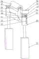
图1为本发明提供的整体结构示意图;Fig. 1 is the overall structure schematic diagram provided by the present invention;
图2为本发明提供的整体结构剖视图;Figure 2 is a sectional view of the overall structure provided by the present invention;
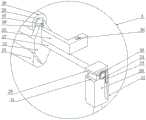
图3为本发明提供的后视立体图;Figure 3 is a rear perspective view provided by the present invention;
图4为本发明提供的检测机构立体图;Figure 4 is a perspective view of the detection mechanism provided by the present invention;
图5为本发明提供的连接壳立体图;Fig. 5 is a perspective view of the connecting shell provided by the present invention;
图6为本发明提供的支撑架立体图;Figure 6 is a perspective view of the support frame provided by the present invention;
图7为本发明提供的连接块立体图;Figure 7 is a perspective view of the connection block provided by the present invention;
图8为本发明提供的U型架立体图;Fig. 8 is a perspective view of a U-shaped frame provided by the present invention;
图9为本发明提供的滑块立体图;Fig. 9 is a perspective view of a slider provided by the present invention;
图10为本发明提供的滑块剖视图;Fig. 10 is a sectional view of the slider provided by the present invention;
图11为本发明提供的图6中A部结构放大图。Fig. 11 is an enlarged view of the structure of part A in Fig. 6 provided by the present invention.
图中:1、箱体;2、开口;3、第一限位杆;4、第一丝杆;5、第一电动推杆;6、U型架;7、第一电机;8、支撑腿;9、第二电机;1O、滑块;11、支撑板;12、膜电极本体;13、第二电动推杆;14、滑轨支架;15、气泵;16、连接管;17、第三电机;18、第二丝杆;19、第二限位杆;20、连接块;21、支撑架;22、连接壳;23、风嘴;24、固定块;25、绝缘辊;26、导电辊;27、固定杆;28、橡胶卡块;29、内支撑筒;30、限位块;31、开槽;32、第三推杆;33、齿板;34、齿轮;35、卡块;36、卡槽;37、滑动方块;38、滑动方槽;39、限位支条;40、方口;41、连接杆;42、连接底座;43、滑轮;44、支条卡口;45、第一侧口;46、固定卡块;47、第二侧口;48、弹簧;49、方板滑块;50、电流电压控制器;51、红外热成像及光学成像设备。In the figure: 1. Box body; 2. Opening; 3. The first limit rod; 4. The first screw rod; 5. The first electric push rod; 6. U-shaped frame; 7. The first motor; 8. Support Leg; 9, second motor; 1O, slider; 11, support plate; 12, membrane electrode body; 13, second electric push rod; 14, slide rail bracket; 15, air pump; 16, connecting pipe; 17, the first Three motors; 18, second screw mandrel; 19, second limit rod; 20, connecting block; 21, support frame; 22, connecting shell; 23, air nozzle; 24, fixed block; 25, insulating roller; 26, Conductive roller; 27, fixed rod; 28, rubber block; 29, inner support cylinder; 30, limit block; 31, slotting; 32, third push rod; 33, tooth plate; 34, gear; 35, card block; 36, card slot; 37, sliding square; 38, sliding square groove; 39, limit support bar; 40, square mouth; 41, connecting rod; 42, connecting base; 43, pulley; 44, support bar bayonet ; 45, the first side port; 46, fixed block; 47, the second side port; 48, spring; 49, square plate slider; 50, current and voltage controller; 51, infrared thermal imaging and optical imaging equipment.
具体实施方式Detailed ways
以下由特定的具体实施例说明本发明的实施方式,熟悉此技术的人士可由本说明书所揭露的内容轻易地了解本发明的其他优点及功效,显然,所描述的实施例是本发明一部分实施例,而不是全部的实施例。基于本发明中的实施例,本领域普通技术人员在没有做出创造性劳动前提下所获得的所有其他实施例,都属于本发明保护的范围。The implementation mode of the present invention is illustrated by specific specific examples below, and those who are familiar with this technology can easily understand other advantages and effects of the present invention from the contents disclosed in this description. Obviously, the described embodiments are a part of the present invention. , but not all examples. Based on the embodiments of the present invention, all other embodiments obtained by persons of ordinary skill in the art without making creative efforts belong to the protection scope of the present invention.
参照附图1-11,本发明提供的一种膜电极穿孔缺陷及涂层均匀度一体化检测装置,包括箱体1,所述箱体1内部固定设有支撑板11,所述支撑板11顶部设有膜电极本体12,所述箱体1内部设有检测机构;Referring to the accompanying drawings 1-11, the present invention provides an integrated detection device for membrane electrode perforation defects and coating uniformity, including a box body 1, a
所述检测机构包括两个检测组件,所述检测组件包括两个检测单元,两个所述检测单元分别设于支撑板11顶部和底部,所述检测单元包括支撑架21,所述支撑架21一侧通过轴承连接有绝缘辊25,所述支撑架21另一侧设有内支撑筒29,所述内支撑筒29两侧均固定连接有滑动方块37,所述支撑架21两侧均开设有滑动方槽38,两个所述滑动方块37分别在两个所述滑动方槽38内部滑动连接,所述内支撑筒29外部通过轴承套设有导电辊26,其中一个所述检测组件的两个检测单元的支撑架21两侧均固定连接有固定杆27,两个所述固定杆27一侧均固定连接有限位块30,两个所述限位块30一侧均设有连接块20,两个所述连接块20一侧均开设有开槽31,两个所述限位块30分别与两个所述开槽31相扣合,两个所述连接块20一侧均固定设有第二电动推杆13,两个所述第二电动推杆13均与箱体1固定连接,所述箱体1内部固定设有电流电压控制器50,所述电流电压控制器50与导电辊26电性连接,所述箱体1顶部固定设有红外热成像及光学成像设备51;The detection mechanism includes two detection assemblies, the detection assembly includes two detection units, and the two detection units are respectively arranged on the top and bottom of the
本实施方案中,启动第二电动推杆13,第二电动推杆13启动并推动连接块20移动,连接块20带动限位块30移动,使限位块30带动固定杆27移动,固定杆27带动支撑架21移动,使支撑架21一侧的导电辊26与膜电极本体12相接触,通过电流电压控制器50与两个导电辊26通电,使两个导电辊26对膜电极本体12进行微电流检测,通过红外热成像及光学成像设备51拍摄快速观察表面缺陷,同时热成像拍摄可监测膜电极热量分布状况,从而确定穿孔位置;In this embodiment, start the second
其中,为了实现转动的目的,本装置采用如下技术方案实现的:所述固定杆27外部套设有橡胶卡块28,所述固定杆27与橡胶卡块28相接触,所述橡胶卡块28固定嵌设于开槽31内部,所述固定杆27外部固定套设有齿轮34,所述连接块20一侧固定设有第三推杆32,所述第三推杆32输出端固定连接有齿板33,所述齿板33与齿轮34相啮合,启动支撑板11底部的第三推杆32,第三推杆32启动并推动齿板33伸出,使齿板33带动齿轮34转动,齿轮34带动固定杆27转动,使固定杆27带动支撑架21转动,使支撑架21带动绝缘辊25和导电辊26转动,从而使绝缘辊25与膜电极本体12相接触,此时卡块35转动到固定杆27另一侧;Among them, in order to achieve the purpose of rotation, this device adopts the following technical scheme to realize: the outside of the fixed
其中,为了实现传动的目的,本装置采用如下技术方案实现的:其中一个所述检测组件的两个检测单元的支撑架21两侧均固定连接有卡块35,两个所述卡块35一侧均开设有卡槽36,所述箱体1内部设有传动机构,所述传动机构包括第一丝杆4和第一限位杆3,所述第一丝杆4两端与箱体1内部两侧壁通过轴承连接,所述第一限位杆3两端与箱体1内部两侧壁固定连接,所述箱体1一侧固定设有第二电机9,所述第二电机9输出端与第一丝杆4固定连接,所述第一丝杆4外部通过螺纹套设有滑块10,所述第一限位杆3贯穿滑块10并与滑块10滑动连接,所述滑块10一侧开设有支条卡口44,所述箱体1内部固定设有限位支条39,所述限位支条39贯穿支条卡口44,所述滑块10一侧设有两个限位组件,所述限位组件包括方口40,所述方口40开设于滑块10一侧,所述方口40一侧开设有第一侧口45,所述第一侧口45内部设有固定卡块46,所述固定卡块46一侧固定连接有连接杆41,所述滑块10一侧开设有第二侧口47,所述连接杆41贯穿第二侧口47,所述连接杆41外部套设有弹簧48,所述连接杆41外部固定套设有方板滑块49,所述方板滑块49在第二侧口47内部滑动,所述连接杆41一端固定连接有连接底座42,所述连接底座42内侧通过轴承连接有滑轮43,所述滑轮43与限位支条39相接触,启动第二电机9,第二电机9启动并带动第一丝杆4转动,第一丝杆4转动并带动滑块10移动,同时滑块10在限位支条39上滑动,首先支撑板11顶部的卡块35进入方口40内,滑块10推动卡块35移动,同时滑轮43在限位支条39上滑动,使滑轮43向上移动并带动连接底座42和连接杆41移动,使连接杆41推动固定卡块46移动,使固定卡块46卡入卡槽36内,使滑块10带动卡块35移动更加稳定,卡块35带动支撑架21移动,支撑架21带动固定杆27移动,固定杆27带动限位块30移动,同时固定杆27从橡胶卡块28内滑出,同时支撑架21另一侧的固定杆27在滑轨支架14上滑行,使导电辊26在膜电极本体12上滚动;Among them, in order to achieve the purpose of transmission, the device is realized by adopting the following technical scheme: both sides of the
其中,为了实现控制的目的,本装置采用如下技术方案实现的:另外一个所述检测组件的两个检测单元的支撑架21一侧通过轴承连接有U型架6,所述U型架6一侧固定连接有两个第一电动推杆5,两个所述第一电动推杆5与箱体1固定连接,所述U型架6一侧固定连接有第一电机7,所述第一电机7输出端与支撑架21固定连接,启动支撑板11一侧的第一电动推杆5,第一电动推杆5启动并推动U型架6移动,使U型架6一侧的支撑架21底部的导电辊26与膜电极本体12接触,同时启动支撑板11底部的U型架6一侧的第一电机7,使第一电机7启动并带动支撑架21转动,使支撑架21带动绝缘辊25和导电辊26转动;Wherein, in order to achieve the purpose of control, this device adopts the following technical scheme to realize: one side of the
其中,为了实现穿孔检测的目的,本装置采用如下技术方案实现的:所述支撑板11底部设有穿孔检测机构,所述穿孔检测机构包括连接壳22,所述连接壳22设于支撑板11底部一侧,所述连接壳22一侧开设有多个风嘴23,所述连接壳22底部固定设有固定块24,所述箱体1内部设有第二丝杆18和第二限位杆19,所述第二丝杆18两端与箱体1两侧壁通过轴承连接,所述第二限位杆19两端与箱体1两侧壁固定连接,所述第二丝杆18贯穿固定块24并与固定块24通过螺纹连接,所述第二限位杆19贯穿固定块24并与固定块24滑动连接,所述箱体1一侧固定设有第三电机17,所述第三电机17输出端与第二丝杆18固定连接,所述连接壳22一侧固定连接有连接管16,所述连接管16一端固定连接有气泵15,所述气泵15固定设于箱体1底部,启动第三电机17,第三电机17启动并带动第二丝杆18转动,使第二丝杆18带动固定块24移动,固定块24带动连接壳22移动,同时气泵15启动并将氢气通过连接管16输入连接壳22内,使连接壳22在膜电极本体12底部滑行,使风嘴23将氢气吹向膜电极本体12,氢气穿过膜电极本体12并与膜电极本体12另一侧的空气在催化层中的催化剂的催化作用下发生化学反应;Among them, in order to achieve the purpose of perforation detection, this device adopts the following technical scheme: the bottom of the
其中,为了实现支撑限位的目的,本装置采用如下技术方案实现的:所述箱体1内部设有两个支撑组件,所述支撑组件包括滑轨支架14,所述固定杆27贯穿滑轨支架14并与滑轨支架14滑动连接,滑轨支架14具有支撑限位固定杆27的作用。Among them, in order to achieve the purpose of supporting and limiting, this device adopts the following technical scheme to realize: the inside of the box 1 is provided with two supporting components, the supporting components include a
其中,为了实现支撑的目的,本装置采用如下技术方案实现的:所述箱体1底部四角均固定连接有支撑腿8,所述箱体1一侧开设有开口2,支撑腿8具有支撑箱体1作用。Among them, in order to achieve the purpose of support, this device adopts the following technical scheme to realize: the four corners of the bottom of the box 1 are fixedly connected with
本发明的使用过程如下:在使用本发明时,将膜电极本体12放入支撑板11上,使膜电极本体12顶部和底部暴露在空气中;The use process of the present invention is as follows: when using the present invention, the
进行涂层均匀度检测时,启动支撑板11一侧的第一电动推杆5,第一电动推杆5启动并推动U型架6移动,使U型架6一侧的支撑架21底部的导电辊26与膜电极本体12接触,同时启动支撑板11底部的U型架6一侧的第一电机7,使第一电机7启动并带动支撑架21转动,使支撑架21带动绝缘辊25和导电辊26转动,使支撑板11底部的绝缘辊25与膜电极本体12底部接触,同时启动第二电动推杆13,第二电动推杆13启动并推动连接块20移动,连接块20带动限位块30移动,使限位块30带动固定杆27移动,固定杆27带动支撑架21移动,使支撑架21一侧的导电辊26与膜电极本体12相接触,此时启动支撑板11底部的第三推杆32,第三推杆32启动并推动齿板33伸出,使齿板33带动齿轮34转动,齿轮34带动固定杆27转动,使固定杆27带动支撑架21转动,使支撑架21带动绝缘辊25和导电辊26转动,从而使绝缘辊25与膜电极本体12相接触,此时卡块35转动到固定杆27另一侧,此时膜电极本体12顶部与两个导电辊26相接触,膜电极本体12底部与两个绝缘辊25相接触,启动第二电机9,第二电机9启动并带动第一丝杆4转动,第一丝杆4转动并带动滑块10移动,同时滑块10在限位支条39上滑动,首先支撑板11顶部的卡块35进入方口40内,滑块10推动卡块35移动,同时滑轮43在限位支条39上滑动,使滑轮43向上移动并带动连接底座42和连接杆41移动,使连接杆41推动固定卡块46移动,使固定卡块46卡入卡槽36内,使滑块10带动卡块35移动更加稳定,卡块35带动支撑架21移动,支撑架21带动固定杆27移动,固定杆27带动限位块30移动,同时固定杆27从橡胶卡块28内滑出,同时支撑架21另一侧的固定杆27在滑轨支架14上滑行,使导电辊26在膜电极本体12上滚动,测膜电极本体12顶部的均匀度时,内支撑筒29两侧的滑动方块37在滑动方槽38内上下滑动并对膜电极本体12上的扩散层进行检测,通过电流电压控制器50对导电辊26通电并对膜电极本体12表面的扩散层施加电压,通过调节导电辊26与另外一个导电辊26在膜电极本体12上距离,可对扩散层区间下电压通过的电流值进行监测,根据扩散层的电流标准曲线图,将电流值转换为扩散层上微孔层载量,得到气体扩散基底层上微孔层是否涂抹均匀,同理膜电极本体12底部也是相同的方法进行检测,通过控制膜电极本体12顶部与两个绝缘辊25相接触,膜电极本体12底部与两个导电辊26相接触,通过传动机构控制底部的导电辊26移动从而进行膜电极本体12底部的涂层均匀性进行检测;When performing coating uniformity detection, start the first electric push rod 5 on one side of the support plate 11, the first electric push rod 5 starts and promotes the U-shaped frame 6 to move, so that the bottom of the support frame 21 on the U-shaped frame 6 side The conductive roller 26 is in contact with the membrane electrode body 12, and at the same time starts the first motor 7 on the side of the U-shaped frame 6 at the bottom of the support plate 11, so that the first motor 7 starts and drives the support frame 21 to rotate, so that the support frame 21 drives the insulating roller 25 Rotate with the conductive roller 26, make the insulating roller 25 at the bottom of the support plate 11 contact the bottom of the membrane electrode body 12, start the second electric push rod 13 at the same time, the second electric push rod 13 starts and pushes the connecting block 20 to move, and the connecting block 20 drives The limit block 30 moves, so that the limit block 30 drives the fixed rod 27 to move, and the fixed rod 27 drives the support frame 21 to move, so that the conductive roller 26 on one side of the support frame 21 is in contact with the membrane electrode body 12, and at this time, the support plate 11 is started The third push rod 32 at the bottom, the third push rod 32 starts and promotes the tooth plate 33 to stretch out, so that the tooth plate 33 drives the gear 34 to rotate, and the gear 34 drives the fixed rod 27 to rotate, so that the fixed rod 27 drives the support frame 21 to rotate, so that The support frame 21 drives the insulating roller 25 and the conductive roller 26 to rotate, so that the insulating roller 25 is in contact with the membrane electrode body 12. At this time, the
穿孔缺陷检测时,通过启动第一电机7,使第一电机7带动支撑架21转动,使膜电极本体12顶部和底部均与绝缘辊25相接触,此时启动第一电动推杆5,使第一电动推杆5带动U型架6移动,使U型架6带动两个绝缘辊25移出膜电极本体12表面,同时启动第三推杆32,使第三推杆32推动齿板33移动,齿板33带动齿轮34转动,使齿轮34带动固定杆27和支撑架21转动,使膜电极本体12顶部和底部分别与导电辊26相接触,通过启动第二电机9带动第一丝杆4转动,使第一丝杆4带动滑块10移动,使滑块10在限位支条39上滑动,两个卡块35进入方口40内,滑块10推动卡块35移动,同时滑轮43在限位支条39上滑动,使滑轮43移动并带动连接底座42和连接杆41移动,使连接杆41推动固定卡块46移动,使固定卡块46卡入卡槽36内,使滑块10带动卡块35移动更加稳定,卡块35带动支撑架21移动,支撑架21带动固定杆27移动,固定杆27带动限位块30移动,同时固定杆27从橡胶卡块28内滑出,同时支撑架21另一侧的固定杆27在滑轨支架14上滑行,使两个导电辊26分别在膜电极本体12顶部和底部滚动,通过电流电压控制器50与两个导电辊26通电,使两个导电辊26对膜电极本体12进行微电流检测,在滚动过程中,如果膜电极本体12存在缺陷,则会造成两个导电辊26之间通电,使两个导电辊26短路,造成电流波动值较大,将两个导电辊26收回,此时启动第三电机17,第三电机17启动并带动第二丝杆18转动,使第二丝杆18带动固定块24移动,固定块24带动连接壳22移动,同时气泵15启动并将氢气通过连接管16输入连接壳22内,使连接壳22在膜电极本体12底部滑行,使风嘴23将氢气吹向膜电极本体12,氢气穿过膜电极本体12并与膜电极本体12另一侧的空气在催化层中的催化剂的催化作用下发生化学反应,膜电极本体12上产生热量,通过红外热成像及光学成像设备51拍摄快速观察表面缺陷,同时热成像拍摄可监测膜电极热量分布状况,从而确定穿孔位置。When detecting perforation defects, by starting the first motor 7, the first motor 7 drives the support frame 21 to rotate, so that the top and bottom of the membrane electrode body 12 are in contact with the insulating roller 25, and at this time the first electric push rod 5 is started to make the The first electric push rod 5 drives the U-shaped frame 6 to move, so that the U-shaped frame 6 drives the two insulating rollers 25 to move out of the surface of the membrane electrode body 12, and at the same time starts the third push rod 32, so that the third push rod 32 pushes the tooth plate 33 to move , the tooth plate 33 drives the gear 34 to rotate, so that the gear 34 drives the fixed rod 27 and the support frame 21 to rotate, so that the top and bottom of the membrane electrode body 12 are respectively in contact with the conductive roller 26, and the first screw mandrel 4 is driven by starting the second motor 9 Rotate to make the first screw mandrel 4 drive the slider 10 to move, so that the slider 10 slides on the limit support bar 39, the two blocks 35 enter the square opening 40, the slider 10 pushes the block 35 to move, and the pulley 43 Slide on the limit support bar 39 to make the pulley 43 move and drive the connecting base 42 and the connecting rod 41 to move, so that the connecting rod 41 pushes the fixed block 46 to move, so that the fixed block 46 is snapped into the draw-in groove 36, so that the slider 10 drives the block 35 to move more stably, the block 35 drives the support frame 21 to move, the support frame 21 drives the fixed rod 27 to move, the fixed rod 27 drives the limit block 30 to move, and the fixed rod 27 slides out from the rubber block 28 at the same time, At the same time, the fixed rod 27 on the other side of the support frame 21 slides on the slide rail bracket 14, so that the two conductive rollers 26 roll on the top and bottom of the membrane electrode body 12 respectively, and the two conductive rollers 26 are energized by the current and voltage controller 50, Make the two conductive rollers 26 carry out microcurrent detection to the membrane electrode body 12. During the rolling process, if there is a defect in the
以上所述,仅是本发明的较佳实施例,任何熟悉本领域的技术人员均可能利用上述阐述的技术方案对本发明加以修改或将其修改为等同的技术方案。因此,依据本发明的技术方案所进行的任何简单修改或等同置换,尽属于本发明要求保护的范围。The above descriptions are only preferred embodiments of the present invention, and any person skilled in the art may use the above-mentioned technical solutions to modify the present invention or modify it into an equivalent technical solution. Therefore, any simple modification or equivalent replacement made according to the technical solution of the present invention falls within the protection scope of the present invention.
Claims (10)
Priority Applications (1)
| Application Number | Priority Date | Filing Date | Title |
|---|---|---|---|
| CN202211394237.3ACN116124784A (en) | 2022-11-08 | 2022-11-08 | Membrane electrode perforation defect and coating uniformity integrated detection device |
Applications Claiming Priority (1)
| Application Number | Priority Date | Filing Date | Title |
|---|---|---|---|
| CN202211394237.3ACN116124784A (en) | 2022-11-08 | 2022-11-08 | Membrane electrode perforation defect and coating uniformity integrated detection device |
Publications (1)
| Publication Number | Publication Date |
|---|---|
| CN116124784Atrue CN116124784A (en) | 2023-05-16 |
Family
ID=86308820
Family Applications (1)
| Application Number | Title | Priority Date | Filing Date |
|---|---|---|---|
| CN202211394237.3APendingCN116124784A (en) | 2022-11-08 | 2022-11-08 | Membrane electrode perforation defect and coating uniformity integrated detection device |
Country Status (1)
| Country | Link |
|---|---|
| CN (1) | CN116124784A (en) |
Citations (9)
| Publication number | Priority date | Publication date | Assignee | Title |
|---|---|---|---|---|
| CN1695071A (en)* | 2002-09-06 | 2005-11-09 | 通用汽车公司 | Method for detecting electrical defects in membrane electrode assemblies |
| CN103575736A (en)* | 2012-07-30 | 2014-02-12 | 现代自动车株式会社 | Pinhole inspection system and apparatus for membrane electrode assembly of fuel cell |
| KR20180070394A (en)* | 2016-12-16 | 2018-06-26 | 현대자동차주식회사 | Method and apparatus for detecting the defect of a fuel cell membrane-electrode assembly |
| CN109799237A (en)* | 2019-01-21 | 2019-05-24 | 深圳市南科燃料电池有限公司 | Defect detection device and detection method |
| CN110231344A (en)* | 2019-07-17 | 2019-09-13 | 佛山市清极能源科技有限公司 | A kind of film electrode fault, which quickly sieves, picks method and apparatus |
| CN210347486U (en)* | 2019-07-17 | 2020-04-17 | 佛山市清极能源科技有限公司 | Online membrane electrode defect detection equipment |
| CN210572003U (en)* | 2019-07-17 | 2020-05-19 | 佛山市清极能源科技有限公司 | Quick screening equipment for membrane electrode defects |
| CN111473918A (en)* | 2020-05-21 | 2020-07-31 | 上海亿氢科技有限公司 | MEA leakage detection device and method based on infrared imaging technology |
| CN112213369A (en)* | 2020-09-07 | 2021-01-12 | 浙江锋源氢能科技有限公司 | A kind of defect detection method of fuel cell membrane electrode |
- 2022
- 2022-11-08CNCN202211394237.3Apatent/CN116124784A/enactivePending
Patent Citations (9)
| Publication number | Priority date | Publication date | Assignee | Title |
|---|---|---|---|---|
| CN1695071A (en)* | 2002-09-06 | 2005-11-09 | 通用汽车公司 | Method for detecting electrical defects in membrane electrode assemblies |
| CN103575736A (en)* | 2012-07-30 | 2014-02-12 | 现代自动车株式会社 | Pinhole inspection system and apparatus for membrane electrode assembly of fuel cell |
| KR20180070394A (en)* | 2016-12-16 | 2018-06-26 | 현대자동차주식회사 | Method and apparatus for detecting the defect of a fuel cell membrane-electrode assembly |
| CN109799237A (en)* | 2019-01-21 | 2019-05-24 | 深圳市南科燃料电池有限公司 | Defect detection device and detection method |
| CN110231344A (en)* | 2019-07-17 | 2019-09-13 | 佛山市清极能源科技有限公司 | A kind of film electrode fault, which quickly sieves, picks method and apparatus |
| CN210347486U (en)* | 2019-07-17 | 2020-04-17 | 佛山市清极能源科技有限公司 | Online membrane electrode defect detection equipment |
| CN210572003U (en)* | 2019-07-17 | 2020-05-19 | 佛山市清极能源科技有限公司 | Quick screening equipment for membrane electrode defects |
| CN111473918A (en)* | 2020-05-21 | 2020-07-31 | 上海亿氢科技有限公司 | MEA leakage detection device and method based on infrared imaging technology |
| CN112213369A (en)* | 2020-09-07 | 2021-01-12 | 浙江锋源氢能科技有限公司 | A kind of defect detection method of fuel cell membrane electrode |
Non-Patent Citations (1)
| Title |
|---|
| 曹涛锋 等: ""质子交换膜燃料电池温度和电流分布同步测定"", 《化工学报》, no. 1, 15 May 2011 (2011-05-15)* |
Similar Documents
| Publication | Publication Date | Title |
|---|---|---|
| CN210347486U (en) | Online membrane electrode defect detection equipment | |
| CN115508371B (en) | Detection system for online defect of membrane electrode | |
| US7695970B2 (en) | Optical fiber based fluorescence sensor for in-situ measurement and control of fuel cells | |
| KR101251229B1 (en) | Apparatus for detecting aligned position of membrane electrode assembly and gas diffusion layer and the method thereof | |
| CN115585735B (en) | A detection device and detection method for membrane electrode gas diffusion layer microporous coating | |
| CN110231345A (en) | A kind of film electrode fault online test method and equipment | |
| CN116124784A (en) | Membrane electrode perforation defect and coating uniformity integrated detection device | |
| KR20120061102A (en) | Test device for hydrogen permeation of steel plate | |
| CN211346676U (en) | Detection equipment for detecting flatness of scraper | |
| CN202403689U (en) | Continuous thickness measuring device for films | |
| KR20100075295A (en) | Apparatus and method for testing defects of electrolyte membrane and cell for sofc using fluorescent liquid | |
| CN115343331B (en) | Efficient membrane electrode defect detection device | |
| CN215866695U (en) | A test device for accelerating carbonization of concrete | |
| CN110567981A (en) | half-cell performance detection device and detection method thereof | |
| CN213022693U (en) | Device for nondestructive testing of hardness of soft package battery | |
| CN213275278U (en) | A infiltration detection device for concrete | |
| Prasad | Investigation and propagation of defects in the membrane electrode assembly of polymer electrolyte membrane fuel cells: quality control analysis | |
| CN221860560U (en) | Conductive metal film sheet resistance detection equipment | |
| CN212806867U (en) | From type paper detection mechanism | |
| CN219495081U (en) | Blade surface smoothness detection device | |
| CN219977988U (en) | Enameled wire tensile testing device and system | |
| CN222318787U (en) | Digital printing ink detection equipment | |
| CN118640855B (en) | Device and method for measuring thickness of electrode carbon felt of all-vanadium redox flow battery | |
| CN119029640B (en) | A gas sensor electrode batch heat treatment and automatic pairing device | |
| CN219871144U (en) | Contrast type blood electrolyte detection device |
Legal Events
| Date | Code | Title | Description |
|---|---|---|---|
| PB01 | Publication | ||
| PB01 | Publication | ||
| SE01 | Entry into force of request for substantive examination | ||
| SE01 | Entry into force of request for substantive examination |