CN116115289A - Clip applier - Google Patents
Clip applierDownload PDFInfo
- Publication number
- CN116115289A CN116115289ACN202111339817.8ACN202111339817ACN116115289ACN 116115289 ACN116115289 ACN 116115289ACN 202111339817 ACN202111339817 ACN 202111339817ACN 116115289 ACN116115289 ACN 116115289A
- Authority
- CN
- China
- Prior art keywords
- jaw assembly
- clip
- release
- stopper
- arm
- Prior art date
- Legal status (The legal status is an assumption and is not a legal conclusion. Google has not performed a legal analysis and makes no representation as to the accuracy of the status listed.)
- Pending
Links
Images


Classifications
- A—HUMAN NECESSITIES
- A61—MEDICAL OR VETERINARY SCIENCE; HYGIENE
- A61B—DIAGNOSIS; SURGERY; IDENTIFICATION
- A61B17/00—Surgical instruments, devices or methods
- A61B17/12—Surgical instruments, devices or methods for ligaturing or otherwise compressing tubular parts of the body, e.g. blood vessels or umbilical cord
- A61B17/128—Surgical instruments, devices or methods for ligaturing or otherwise compressing tubular parts of the body, e.g. blood vessels or umbilical cord for applying or removing clamps or clips
- A61B17/1285—Surgical instruments, devices or methods for ligaturing or otherwise compressing tubular parts of the body, e.g. blood vessels or umbilical cord for applying or removing clamps or clips for minimally invasive surgery
- A—HUMAN NECESSITIES
- A61—MEDICAL OR VETERINARY SCIENCE; HYGIENE
- A61B—DIAGNOSIS; SURGERY; IDENTIFICATION
- A61B17/00—Surgical instruments, devices or methods
- A61B17/12—Surgical instruments, devices or methods for ligaturing or otherwise compressing tubular parts of the body, e.g. blood vessels or umbilical cord
- A61B17/128—Surgical instruments, devices or methods for ligaturing or otherwise compressing tubular parts of the body, e.g. blood vessels or umbilical cord for applying or removing clamps or clips
- A—HUMAN NECESSITIES
- A61—MEDICAL OR VETERINARY SCIENCE; HYGIENE
- A61B—DIAGNOSIS; SURGERY; IDENTIFICATION
- A61B17/00—Surgical instruments, devices or methods
- A61B17/12—Surgical instruments, devices or methods for ligaturing or otherwise compressing tubular parts of the body, e.g. blood vessels or umbilical cord
- A61B2017/12004—Surgical instruments, devices or methods for ligaturing or otherwise compressing tubular parts of the body, e.g. blood vessels or umbilical cord for haemostasis, for prevention of bleeding
Landscapes
- Health & Medical Sciences (AREA)
- Surgery (AREA)
- Life Sciences & Earth Sciences (AREA)
- Heart & Thoracic Surgery (AREA)
- Nuclear Medicine, Radiotherapy & Molecular Imaging (AREA)
- Vascular Medicine (AREA)
- Engineering & Computer Science (AREA)
- Biomedical Technology (AREA)
- Reproductive Health (AREA)
- Medical Informatics (AREA)
- Molecular Biology (AREA)
- Animal Behavior & Ethology (AREA)
- General Health & Medical Sciences (AREA)
- Public Health (AREA)
- Veterinary Medicine (AREA)
- Surgical Instruments (AREA)
Abstract
Translated fromChinese
Description
Translated fromChinese技术领域technical field
本发明涉及医疗器械技术领域,特别是涉及一种施夹钳。The invention relates to the technical field of medical instruments, in particular to a clip applier.
背景技术Background technique
在微创手术中,常采用施夹钳将夹子固定于组织或血管上,以达到止血、结扎闭合的作用。夹子具有相对设置的两个夹臂,两个夹臂能够闭合以使目标组织固定于两个夹臂之间。In minimally invasive surgery, clip applicators are often used to fix the clips on tissues or blood vessels to achieve hemostasis and ligation and closure. The clip has two opposite clamping arms, and the two clamping arms can be closed to fix the target tissue between the two clamping arms.
在施夹前,需要将夹子从施夹钳内推至施夹钳的钳口组件的远端。钳口组件包括两个钳臂,每一个钳臂中设有与夹子对应的止挡件。夹子移动到钳口组件的远端后,夹子的夹臂和与其对应的止挡件抵接,使得夹子在钳口组件远端的位置保持稳定。Before clip application, the clip needs to be pushed from the inside of the clip applier to the distal end of the jaw assembly of the clip applier. The jaw assembly includes two tong arms, each of which is provided with a stopper corresponding to the clip. After the clip moves to the far end of the jaw assembly, the clip arm of the clip abuts against the corresponding stopper, so that the position of the clip at the far end of the jaw assembly remains stable.
现有技术中,在钳口组件闭合以闭合夹子后,止挡件仍然与夹子抵接,使得夹子难以脱离钳口组件,从而在打开钳口组件时,钳口组件会对夹子产生作用力,导致夹子对组织或血管造成撕扯,增加了微创手术的风险。In the prior art, after the jaw assembly is closed to close the clip, the stopper still abuts against the clip, making it difficult for the clip to disengage from the jaw assembly, so that when the jaw assembly is opened, the jaw assembly exerts force on the clip, This can cause the clip to tear tissue or blood vessels, increasing the risk of minimally invasive procedures.
基于上述,有必要对现有技术中的施夹钳进行改进。Based on the above, it is necessary to improve the clip applier in the prior art.
发明内容Contents of the invention
针对现有技术的不足,本发明旨在提供一种施夹钳,解决了钳口组件打开时会对夹子的产生作用力而导致夹子对组织造成撕扯的技术问题。Aiming at the deficiencies of the prior art, the present invention aims to provide a clip applier, which solves the technical problem that the clip will tear the tissue due to the force exerted on the clip when the jaw assembly is opened.
本发明通过以下技术方案实现:The present invention is realized through the following technical solutions:
一种施夹钳,包括钳口组件和被作用件,所述被作用件可操作的位于所述钳口组件中,所述钳口组件具有止挡件和释放机构,所述止挡件与所述被作用件抵接以使所述被作用件保持于所述钳口组件,所述释放机构能驱动所述止挡件移动,以使所述止挡件与所述被作用件脱离,从而使所述被作用件处于可脱离所述钳口组件的状态。A clip applier, comprising a jaw assembly and an acted part, the acted part is operatively located in the jaw assembly, the jaw assembly has a stopper and a release mechanism, the stopper and The affected part abuts to keep the affected part in the jaw assembly, the release mechanism can drive the stopper to move, so that the stopper is separated from the affected part, Thus, the affected part is in a state where it can be detached from the jaw assembly.
作为优选,所述钳口组件的至少一侧具有所述释放机构,所述释放机构包括两个释放元件,响应于所述钳口组件的闭合,每一个所述释放元件的近端均沿第一方向朝向所述钳口组件的近端移动。Preferably, at least one side of the jaw assembly has the release mechanism, the release mechanism includes two release elements, the proximal end of each release element moves along the first One direction moves toward the proximal end of the jaw assembly.
进一步优选,响应于所述钳口组件的闭合,两个所述释放元件的远端相互靠近运动。It is further preferred that the distal ends of the two release elements move towards each other in response to the closing of the jaw assembly.
进一步优选,所述钳口组件包括两个钳臂,一个所述释放元件的远端和一个所述钳臂枢转连接,另一个所述释放元件的远端和另一个所述钳臂枢转连接,两个所述释放元件的近端枢转连接。Further preferably, the jaw assembly includes two pliers arms, the distal end of one release element is pivotally connected to one of the pliers arms, and the distal end of the other release element is pivotally connected to the other pliers arm. connected, the proximal ends of the two release elements are pivotally connected.
进一步优选,所述止挡件与所述释放元件的近端可操作地配合,响应于所述钳口组件的闭合,每一个所述释放元件的近端沿第一方向向所述钳口组件的近端移动以驱动所述止挡件向近端移动,以使所述止挡件与所述被作用件脱离。Further preferably, the stopper is operatively engaged with proximal ends of the release elements, and in response to closure of the jaw assembly, the proximal end of each release element moves toward the jaw assembly in a first direction. The proximal end of the stopper moves to drive the stopper to move proximally, so that the stopper is disengaged from the affected part.
进一步优选,所述钳口组件包括两个钳臂,每一个所述钳臂中均具有所述止挡件,与同一个所述释放机构相配合的两个止挡件的近端通过铰接部相连接。Further preferably, the jaw assembly includes two pliers arms, each of the pliers arms has the stopper, and the proximal ends of the two stoppers matched with the same release mechanism pass through the hinge connected.
进一步优选,所述释放机构还包括第一销轴,位于所述钳口组件同一侧的两个释放元件的近端通过第一销轴枢转连接,所述释放元件的近端通过所述第一销轴与所述铰接部可操作地配合,以驱动所述止挡件向近端移动。Further preferably, the release mechanism further includes a first pin shaft, the proximal ends of the two release elements located on the same side of the jaw assembly are pivotally connected through the first pin shaft, and the proximal ends of the release elements pass through the first pin shaft. A pin operatively cooperates with the hinge part to drive the stopper to move proximally.
作为优选,所述钳口组件包括两个钳臂,所述被作用件为夹子,所述止挡件与所述夹子的至少一部分抵接以将所述夹子保持在所述钳臂中。Preferably, the jaw assembly includes two pliers arms, the acted member is a clip, and the stopper abuts at least a part of the clip to keep the clip in the pliers arms.
作为优选,所述钳口组件包括两个钳臂,所述止挡件设置于所述钳臂,所述被作用件为夹子,所述夹子包括两个夹臂,一个所述夹臂的至少一部分可操作的位于一个所述钳臂中,另一个所述夹臂的至少一部分可操作的位于另一个所述钳臂中,所述止挡件与其所在所述钳臂中的所述夹臂的所述至少一部分相抵接;所述钳口组件的至少一侧设置有所述释放机构,所述释放机构包括两个释放元件,所述止挡件和与其对应的所述释放元件的近端可操作地配合,响应于所述钳口组件的闭合,每一个所述释放元件的近端沿第一方向向近端移动以驱动所述止挡件向近端移动,以使所述止挡件与其所在钳臂中的所述夹臂的所述至少一部分脱离,同时两个所述释放元件的远端相互靠近运动。Preferably, the jaw assembly includes two pliers arms, the stopper is arranged on the pliers arms, the affected part is a clip, and the clip includes two clip arms, at least one of the clip arms A part is operatively located in one of the pliers arms, and at least a part of the other pliers arm is operatively located in the other pliers arm, and the stopper and the clamp arm in the pliers arms The at least one part of the jaw assembly abuts against; at least one side of the jaw assembly is provided with the release mechanism, and the release mechanism includes two release elements, the stopper and the proximal end of the release element corresponding thereto Operably cooperating, in response to the closure of the jaw assembly, the proximal end of each of the release members moves proximally in a first direction to drive the stop member proximally so that the stop The member is disengaged from said at least a part of said clamp arm in said clamp arm, and at the same time the distal ends of the two release elements are moved closer to each other.
进一步优选,一个所述释放元件的远端和一个所述钳臂枢转连接,另一个所述释放元件的远端和另一个所述钳臂枢转连接,两个所述释放元件的近端枢转连接。Further preferably, the distal end of one release element is pivotally connected to one of the pliers arms, the distal end of the other release element is pivotally connected to the other pliers arm, and the proximal ends of the two release elements Pivot connection.
进一步优选,每一个所述夹臂具有耳部,所述夹臂的所述至少一部分包括所述耳部。Further preferably, each of said clamping arms has an ear, said at least a portion of said clamping arm comprising said ear.
进一步优选,每一个所述钳臂上均设有滑槽;所述止挡件包括安装部和限位部,所述安装部可滑动地位于所述滑槽中,所述限位部与所述钳臂的底部之间构成导向空间,所述耳部在所述导向空间内移动时,所述限位部对所述耳部进行约束。Further preferably, a chute is provided on each of the pliers arms; the stopper includes a mounting portion and a limiting portion, the mounting portion is slidably located in the chute, and the limiting portion is connected to the limiting portion. A guiding space is formed between the bottoms of the pliers arms, and when the ear moves in the guiding space, the limiting part constrains the ear.
进一步优选,在所述钳口组件处于打开状态时,任意一个所述安装部的远端从所述安装部所在的滑槽中伸出。Further preferably, when the jaw assembly is in an open state, the distal end of any one of the installation parts protrudes from the slide groove where the installation part is located.
作为优选,所述止挡件具有弹性。Preferably, the stopper is elastic.
进一步优选, 每一个所述止挡件与对应的所述释放元件的近端固定连接。Further preferably, each stopper is fixedly connected to the proximal end of the corresponding release element.
作为优选,所述钳口组件的两侧均设有所述释放机构。Preferably, both sides of the jaw assembly are provided with the release mechanism.
与现有技术相比,本发明的有益效果在于:Compared with prior art, the beneficial effect of the present invention is:
本发明施夹钳通过在钳口组件上设置了释放机构,同时设置止挡件能够在钳口组件的远端和近端之间滑动,使得钳口组件闭合时,释放机构能够带动止挡件朝向钳口组件的近端移动以远离夹子的耳部,由此解除止挡件对耳部的限制作用,从而当钳口组件打开时,钳口组件不会拉扯夹子的夹臂,从而夹子的夹臂不会拉扯组织或血管,降低了微创手术的风险。The clip applier of the present invention is provided with a release mechanism on the jaw assembly, and at the same time, a stopper can slide between the distal end and the proximal end of the jaw assembly, so that when the jaw assembly is closed, the release mechanism can drive the stopper Towards the proximal end of the jaw assembly moves away from the ear of the clip, thereby releasing the restraining effect of the stopper on the ear, so that when the jaw assembly is opened, the jaw assembly does not pull on the arms of the clip so that the clip's The clamp arm will not pull tissue or blood vessels, reducing the risk of minimally invasive surgery.
附图说明Description of drawings
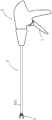
图1是本发明具体实施方式提供的施夹钳的结构示意图;Fig. 1 is a schematic structural view of a clip applier provided in a specific embodiment of the present invention;
图2是本发明具体实施方式提供的施夹钳的部分区域的剖视图;Fig. 2 is a cross-sectional view of a partial area of the clip applier provided by a specific embodiment of the present invention;
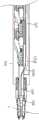
图3是本发明具体实施方式提供的施夹钳的杆身组件的剖视图,其中,推夹组件未与夹子抵接;Fig. 3 is a cross-sectional view of the shaft assembly of the clip applier provided by the specific embodiment of the present invention, wherein the push clip assembly is not in contact with the clip;
图4是本发明具体实施方式提供的施夹钳的杆身组件的剖视图,其中,推夹组件与夹子抵接并将夹子推至钳口组件中;Fig. 4 is a cross-sectional view of the shaft assembly of the clip applier provided by the specific embodiment of the present invention, wherein the push clip assembly abuts against the clip and pushes the clip into the jaw assembly;
图5是本发明具体实施方式提供的夹子的结构示意图;Fig. 5 is a schematic structural view of a clip provided by a specific embodiment of the present invention;
图6是现有技术中施夹钳的钳口组件的结构示意图;Fig. 6 is a schematic structural view of the jaw assembly of the clip applier in the prior art;
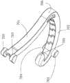
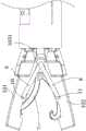
图7是本发明具体实施方式提供的钳口组件第一角度的结构示意图,其中钳口组件中具有夹子且钳口组件是打开状态;Fig. 7 is a schematic structural view of the first angle of the jaw assembly provided by the specific embodiment of the present invention, wherein there is a clip in the jaw assembly and the jaw assembly is in an open state;
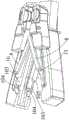
图8是本发明具体实施方式提供的钳口组件第一角度的结构示意图,其中钳口组件中具有夹子且钳口组件是闭合状态;Fig. 8 is a schematic structural view of the first angle of the jaw assembly provided by the specific embodiment of the present invention, wherein there is a clip in the jaw assembly and the jaw assembly is in a closed state;
图9是本发明具体实施方式提供的钳口组件第一角度的剖视图,其中钳口组件中具有夹子且钳口组件是闭合状态;Fig. 9 is a cross-sectional view at a first angle of the jaw assembly provided by a specific embodiment of the present invention, wherein the jaw assembly has a clip and the jaw assembly is in a closed state;
图10是本发明具体实施方式提供的钳口组件第二角度的结构示意图,其中钳口组件中具有夹子且钳口组件是打开状态;Fig. 10 is a schematic structural view of the second angle of the jaw assembly provided by the specific embodiment of the present invention, wherein the jaw assembly has a clip and the jaw assembly is in an open state;
图11是本发明具体实施方式提供的钳口组件第二角度的结构示意图,其中钳口组件中无夹子且钳口组件是打开状态;Fig. 11 is a schematic structural view of the second angle of the jaw assembly provided by the specific embodiment of the present invention, wherein there is no clip in the jaw assembly and the jaw assembly is in an open state;
图12是本发明具体实施方式提供的钳口组件第一角度的剖视图,其中钳口组件中无夹子且钳口组件是打开状态;Fig. 12 is a cross-sectional view of the jaw assembly provided by a specific embodiment of the present invention at a first angle, wherein there is no clip in the jaw assembly and the jaw assembly is in an open state;
图13是本发明具体实施方式提供的钳口组件第一角度的剖视图,其中钳口组件中无夹子且钳口组件是打开状态,并且钳口组件中未安装止挡件;Fig. 13 is a cross-sectional view at a first angle of the jaw assembly provided by a specific embodiment of the present invention, wherein there is no clip in the jaw assembly and the jaw assembly is in an open state, and no stopper is installed in the jaw assembly;
图14是本发明具体实施方式提供的钳口组件的第二钳臂的部分结构示意图;Fig. 14 is a partial structural schematic diagram of the second pliers arm of the jaw assembly provided in the specific embodiment of the present invention;
图15是本发明具体实施方式提供的夹子与止挡件配合方式的示意图;Fig. 15 is a schematic diagram of the cooperation mode of the clip and the stopper provided by the specific embodiment of the present invention;
图16是本发明释放机构运动原理示意图;Fig. 16 is a schematic diagram of the movement principle of the release mechanism of the present invention;
图17是本发明具体实施方式提供的止挡件的结构示意图;Fig. 17 is a schematic structural view of a stopper provided by a specific embodiment of the present invention;
图18是本发明具体实施方式提供的第二钳臂与释放元件配合的示意图;Fig. 18 is a schematic diagram of the cooperation between the second pliers arm and the release element provided by the specific embodiment of the present invention;
以上附图的附图标记:1-钳口组件;101-第一钳臂;102-第二钳臂;103-止挡件;1031-铰接部;1032-安装部;1033-限位部;104-凹陷部;105-底部;106-侧部;107-滑槽;108-缺口;The reference signs of the above drawings: 1-jaw assembly; 101-first tong arm; 102-second tong arm; 103-stopper; 1031-hinge part; 1032-installation part; 1033-limiting part; 104-sag; 105-bottom; 106-side; 107-chute; 108-notch;
2-扳手;201-抵推部;2-wrench; 201-resistance part;
3-壳体;3-shell;
4-杆身组件;401-套管;402-基座;4021-导向槽;4022-导向斜面;403-弹性推杆;404-推夹块;4-shaft assembly; 401-sleeve; 402-base; 4021-guide groove; 4022-guiding slope; 403-elastic push rod; 404-push clamp block;
5-驱动管;501-挡块;5-drive tube; 501-block;
6-弹性体;6 - elastomer;
7-夹子;701-第一夹臂;702-第二夹臂;703-第一耳部;704-第二耳部;705-卡合部;706-连接部;7-clip; 701-first clamping arm; 702-second clamping arm; 703-first ear; 704-second ear; 705-engaging part; 706-connecting part;
8-释放元件;9-第一销轴;10-第二销轴;11-第三销轴;12-移动件。8-release element; 9-first pin shaft; 10-second pin shaft; 11-third pin shaft; 12-moving member.
具体实施方式Detailed ways
为了使本发明的目的、技术方案及优点更加清楚明白,以下结合附图及实施例,对本发明进行进一步详细说明。应当理解,此处所描述的具体实施例仅用以解释本发明,并不用于限定本发明。基于本发明中的实施例,本领域普通技术人员在没有做出创造性劳动前提下所获得的所有其他实施例,都属于本发明保护的范围。In order to make the object, technical solution and advantages of the present invention clearer, the present invention will be further described in detail below in conjunction with the accompanying drawings and embodiments. It should be understood that the specific embodiments described here are only used to explain the present invention, not to limit the present invention. Based on the embodiments of the present invention, all other embodiments obtained by persons of ordinary skill in the art without making creative efforts belong to the protection scope of the present invention.
需要理解的是,本文所用术语“近”、“后”和“远”、“前”是相对于操纵施夹钳的手柄的临床医生而言的。术语“近”、“后”是指靠近临床医生的部分,术语“远”、“前”则是指远离临床医生的部分。即手柄为近端,钳口组件为远端,如某个零部件的近端表示相对靠近手柄的一端,远端则表示相对靠近钳口组件的一端。术语“上”、“下”是以钳口组件的第一钳臂和第二钳臂的相对位置为参考,具体的,第一钳臂在“上”,第二钳臂在“下”。然而,施夹钳可以在许多方向和位置使用,因此这些表达相对位置关系的术语并不是受限和绝对的。It should be understood that the terms "proximal", "rear" and "distal", "anterior" as used herein are relative to the clinician manipulating the handle of the clip applier. The terms "proximal" and "posterior" refer to the part close to the clinician, and the terms "distal" and "anterior" refer to the part away from the clinician. That is, the handle is the proximal end, and the jaw assembly is the distal end. For example, the proximal end of a component means the end relatively close to the handle, and the distal end means the end relatively close to the jaw assembly. The terms "upper" and "lower" refer to the relative positions of the first tong arm and the second tong arm of the jaw assembly, specifically, the first tong arm is "up", and the second tong arm is "down". However, the clip applier can be used in many orientations and positions, so these terms expressing relative positional relationships are not limiting and absolute.
在本发明中,除非另有明确的规定和限定,“相连”、“连接”等术语应做广义理解,例如,可以是固定连接,也可以是可拆卸地连接,还可以是可运动地连接,或成一体;可以是直接相连,也可以通过中间媒介间接相连,可以是两个元件内部的连通或两个元件的相互作用关系如抵接。对于本领域的普通技术人员而言,可以根据具体情况理解上述术语在本发明中的具体含义。需要说明的是,在“相连”、“连接”前有限定语时,其具有相应限定语所限定的含义,只排除明显需要排除的情形,不排除其它可能的情形。In the present invention, terms such as "connected" and "connected" should be interpreted in a broad sense unless otherwise clearly specified and limited, for example, they can be fixedly connected, detachably connected, or movably connected. , or integrated; it can be directly connected or indirectly connected through an intermediary, it can be the internal communication of two elements or the interaction relationship between two elements such as butting. Those of ordinary skill in the art can understand the specific meanings of the above terms in the present invention according to specific situations. It should be noted that when there are qualifiers before "connected" and "connected", it has the meaning defined by the corresponding qualifiers, and only the situations that obviously need to be excluded are excluded, and other possible situations are not excluded.
本文所用术语“轴向”是指套管401的长度方向。The term "axial" as used herein refers to the length direction of the
图1-4、7-14示出了本发明实施例的外科器械,具体是一种施夹钳,用于将夹子7施加到人体上,例如血管或除血管以外的其它组织。1-4, 7-14 show the surgical instrument of the embodiment of the present invention, specifically a clip applicator, which is used to apply the
重点参考图1-2,本实施例施夹钳包括操作组件、自操作组件延伸的杆身组件4、传动机构和设置于杆身组件4远端的钳口组件1。Focusing on FIGS. 1-2 , the clip applier in this embodiment includes an operating assembly, a shaft assembly 4 extending from the operating assembly, a transmission mechanism, and a jaw assembly 1 disposed at the distal end of the shaft assembly 4 .
操作组件包括壳体3和扳手2,扳手2可活动地安装在壳体3上。The operating assembly includes a
重点参考图3,杆身组件4包括夹盒、基座402、推夹组件和套设于夹盒、基座402、推夹组件的套管401。基座402具有较强的刚性,基座402上设有收容推夹组件且供其轴向运动的导向槽4021,导向槽4021的远端设有导向斜面4022,导向斜面4022与轴向呈角度设置。基座402与夹盒安装在一起时,导向斜面4022朝向远端且向夹盒倾斜。在施夹前,夹子7放置于夹盒中,夹盒的侧壁上设有与导向斜面4022对应的开口,推夹组件的远端能从开口处进入夹盒中并在夹子7的后端抵接夹子7以推动其前进。具体而言,推夹组件包括弹性推杆403和连接在弹性推杆403远端的推夹块404。弹性推杆403由多个金属薄片叠合而成,具有弹性,可以弯曲。弹性推杆403和推夹块404能够在导向槽4021内轴向移动。Referring to FIG. 3 , the shaft assembly 4 includes a cartridge case, a
重点参考图4,当弹性推杆403向远端移动至推夹块404抵触到导向斜面4022时,弹性推杆403开始弯曲,推夹块404沿着导向斜面4022倾斜地从夹盒开口处进入夹盒内,从而在夹盒内的夹子7的后端抵接夹子7来推动其前进,使得夹子7进入钳口组件1中。夹子7进入钳口组件1中后,弹性推杆403远端的推夹块404继续从夹子7的后端抵接夹子7,以防止夹子7在施夹过程中向近端(即向后)移动。钳口组件1闭合使得夹子7闭合,钳口组件1再次打开时,弹性推杆403在导向槽4021中沿轴向向近端运动,带动推夹块404沿着导向斜面4022从开口退回至导向槽4021中。在杆身组件4中设置有推夹驱动机构用以对弹性推杆403施力,推夹驱动机构能够推动弹性推杆403向远端(即向前)或近端移动。Referring to FIG. 4 , when the
参考图1-2,钳口组件1包括分别可枢转地相连于杆身组件4的第一钳臂101和第二钳臂102。传动机构包括钳口驱动机构。钳口驱动机构包括驱动管5和套管401。驱动管5收容于操作组件的壳体3内,套管401的近端与驱动管5连接,套管401的远端与钳口组件1相配合。具体而言,钳口组件1的两个钳臂之间具有弹性件,当套管401向远端移动时,钳口组件1能够从套管401的远端被收容于套管401内,此时弹性件被压缩,钳口组件1闭合,当套管401向近端移动时,钳口组件1能够从套管401的远端伸出,弹性件释放能量而使钳口组件1打开。弹性件可以选用弹簧。套管401也构成杆身组件4的一部分。Referring to FIGS. 1-2 , the jaw assembly 1 includes a
扳手2的一端设有抵推部201,抵推部201位于壳体3内。在驱动管5的近端设有移动件12,抵推部201与移动件12远离驱动管5的一端相抵接。由此,通过按压扳手2,能够使抵推部201推动移动件12向远端移动,从而移动件12推动驱动管5和套管401向远端移动。One end of the
驱动管5的外部套设有弹性体6。弹性体6的近端与驱动管5外表面上的挡块501抵接,弹性体6的远端与施夹钳的壳体3内壁抵接。当按压扳手2,使抵推部201推动驱动管5向远端移动时,能够使得套管401向远端移动以使第一钳臂101和第二钳臂102闭合,此时弹性体6储存能量。当松开扳手2时,弹性体6释放能量而使驱动管5向近端移动至复位,从而套管401向近端移动,以使第一钳臂101和第二钳臂102打开。本实施例中弹性体6可选用弹簧。The
本实施例中,施夹钳还包括被作用件,被作用件可操作地位于钳口组件1中。本实施例中被作用件为夹子7。第一钳臂101和第二钳臂102之间可支撑一个夹子7。钳口组件1在打开状态和闭合状态之间切换。钳口组件1的打开状态包括打开到底状态,此时第一钳臂101和第二钳臂102的远端在上、下方向的距离最大。钳口组件1在闭合状态下,第一钳臂101和第二钳臂102的远端在上、下方向的距离最小,钳口组件1的闭合使得夹子7由打开状态转变为闭合状态。In this embodiment, the clip applier further includes an applied part, which is operatively located in the jaw assembly 1 . In this embodiment, the affected part is the
参考图5,夹子7包括两个夹臂和位于两个夹臂之间的连接部706。两个夹臂即第一夹臂701和第二夹臂702。第一夹臂701与第二夹臂702可围绕连接部706彼此相对枢转。第一夹臂701远离连接部706的一端具有两个第一耳部703,一个第一耳部703设于第一夹臂701的一侧,另一个第一耳部703设于第一夹臂701相对的另一侧。第二夹臂702远离连接部706的一端具有卡合部705,第二夹臂702靠近卡合部705处设有两个第二耳部704,一个第二耳部704设于第二夹臂702的一侧,另一个第二耳部704设于第二夹臂702相对的另一侧。在施夹前,夹子7被放置于杆身组件4内的夹盒中,夹子7的第二耳部704能够和夹盒之间形成限位结构,以将夹子7夹持于夹盒中。Referring to FIG. 5 , the
在施夹时,弹性推杆403远端的推夹块404将夹子7推至钳口组件1中,使得夹子7的两个第一耳部703可操作的位于第一钳臂101中,两个第二耳部704可操作的位于第二钳臂102中。夹子7夹持于钳口组件1中后,闭合钳口组件1以闭合夹子7,再打开钳口组件1以使夹子7与钳口组件1脱离,即完成施夹。具体而言,第一钳臂101和第二钳臂102闭合时,带动钳口组件1中的夹子7由打开状态转变为闭合状态。在夹子7处于闭合状态时,第二夹臂702的卡合部705能够卡合于第一夹臂701的两个第一耳部703之间,以使得第一夹臂701和第二夹臂702充分夹紧,从而被置于第一夹臂701和第二夹臂702之间的血管或组织能被有效夹紧、止血。When clamping, the
由于在施夹前,夹子7被放置于施夹钳的杆身组件4中的夹盒中。受限于夹盒的尺寸和内部空间,夹子7被压缩后存储在夹盒中。被压缩是指夹子7的两个夹臂相互靠近,但未卡合。由于夹子7自装配至夹盒后至使用会持续一段时间,这段时间的被压缩,使得夹子7被推出至钳口组件1中后,仍然有保持被压缩后形状的趋势,对其使用造成了一定的影响。Because before clamping, the
图6为现有技术中的施夹钳的钳口组件,其第一钳臂101的结构与第二钳臂102的结构相同,本发明着重描述其第二钳臂102的结构。Fig. 6 is a jaw assembly of a clip applier in the prior art, the structure of the
第二钳臂102包括底部105、设置于底部105一侧的一个侧部106、设置于底部另一侧的另一个侧部106。第二钳臂102的远端对应于第二夹臂702的两个第二耳部704设置有两个凹陷部104,一个凹陷部104设置于第二钳臂102的一个侧部106,另一个凹陷部104设置于第二钳臂102的另一个侧部106。弹性推杆403远端的推夹块404将夹子7从杆身组件4的夹盒中被推至钳口组件1中后,每一个第一耳部703均容置于第一钳臂101中与其对应的凹陷部104内,每一个第二耳部704均容置于第二钳臂102中与其对应的凹陷部104内。为了克服夹子7被推出后仍然保持压缩后形状而影响其使用的技术问题,现有技术中的施夹钳,在第一钳臂101内设置了两个止挡件103,以分别与两个第一耳部703相配合。在第二钳臂102内也设置了两个止挡件103,以分别与两个第二耳部704相配合。每一个止挡件103均是具有弹性的。The
第二钳臂102中的每一个止挡件103大体上沿第二钳臂102的延伸方向设置。一个止挡件103靠近第二钳臂102的一个侧部106设置,且其近端与该侧部106固定连接,远端可上下活动。另一个止挡件103靠近第二钳臂102的另一个侧部106设置,且其近端与该侧部106固定连接,远端可上下活动。每一个止挡件103和第二钳臂102的底部105之间构成了导向空间。由此,夹子7在钳口组件1中运动时,第一夹臂701大体上在第一钳臂101中的两个止挡件103之间移动,第一夹臂701的每一个第一耳部703在与其对应的导向空间内移动。同样的,夹子7在钳口组件1中运动时,第二夹臂702大体上在第二钳臂102中的两个止挡件103之间移动,第二夹臂702的每一个第二耳部704在与其对应的导向空间内移动。从而,第一钳臂101中的每一个止挡件103能在第一夹臂701向远端移动的过程中对与其对应的第一耳部703起到止挡作用,第二钳臂102中的每一个止挡件103能在第二夹臂702向远端移动的过程中对与其对应的第二耳部704起到止挡作用,使得第一夹臂701和第二夹臂702能够逐渐展开至恢复其打开形状,从而克服夹子7被推出后仍然保持压缩后形状而影响其使用的技术问题。当每一个第一耳部703运动至第一钳臂101中与其对应的凹陷部104内,同时每一个第二耳部704运动至第二钳臂102中与其对应的凹陷部104内时,每一个止挡件103的远端与其所在钳臂中的与其对应的耳部相抵接,以将夹子7稳定的夹持于钳口组件1中。Each
现有技术中的施夹钳,第一钳臂101中的止挡件103的近端和与其对应的侧部106固定连接,止挡件103不能沿第一钳臂101的延伸方向运动,即止挡件103不能朝向近端或远端运动。同样的,第二钳臂102中的止挡件103也不能朝向近端或远端运动。由此,当钳口组件1闭合使得第一夹臂701和第二夹臂702闭合而使夹子7夹持于组织或血管上后,容易发生第一耳部703与止挡件103未脱离以及第二耳部704与止挡件103未脱离的现象,从而在钳口组件1打开时,止挡件103会对夹子7的夹臂产生作用力,导致夹子7难以从钳口组件1中脱离,从而夹子7对组织或血管造成撕扯,增加了微创手术的风险。In the clip applier in the prior art, the proximal end of the
为了克服现有技术中夹子7难以从钳口组件1中脱离的技术问题,本实施例对施夹钳进行了改进。In order to overcome the technical problem that the
参考图7-9,本实施例中,钳口组件1具有止挡件103和释放机构,止挡件103能和夹子抵接而使夹子保持于钳口组件1。由于止挡件103的限制,夹子难以脱离钳口组件1。因此,本实施例设置钳口组件1具有释放机构,释放机构能够驱动止挡件103移动,以使止挡件103与夹子脱离,从而能够解除止挡件103对夹子的限制作用,使夹子处于可脱离钳口组件的状态。夹子处于可脱离钳口组件的状态,是指被夹子不再受止挡件的限制,在被夹持物(组织或血管)的作用下可以自钳口组件1脱离,从而不会对被夹持物带来损伤。Referring to FIGS. 7-9 , in this embodiment, the jaw assembly 1 has a
本实施例中,第一钳臂101的结构与第二钳臂102的结构相同,本实施例着重描述第一钳臂101的结构。In this embodiment, the structure of the
重点参考图10、13、14,第一钳臂101具有底部105和两个侧部106,一个侧部106设于底部105的一侧,另一个侧部106设于底部105的另一侧。底部105和两个侧部106使得第一钳臂101的横截面大致为U形。10 , 13 , 14 , the
重点参考图10-14,为了使夹子7的第一耳部703能够更好的容置于第一钳臂101中,在第一钳臂101的远端设置有两个凹陷部104。一个凹陷部104设置于一个侧部106,另一个凹陷部104设置于另一个侧部106。一个第一耳部703能够可操作的容置于第一钳臂101的一个凹陷部104中,另一个第一耳部703能够可操作的容置于第一钳臂101的另一个凹陷部104中。同样的,一个第二耳部704能够可操作的容置于第二钳臂102的一个凹陷部104中,另一个第二耳部704能够可操作的容置于第二钳臂102的另一个凹陷部104中。Referring to FIGS. 10-14 , in order to better accommodate the
参考图10-12,第一钳臂101的每一个侧部106中均安装有一个止挡件103。重点参考图13,第一钳臂101的每一个侧部106的内壁均开设有滑槽107,每个滑槽107大体上沿其所在的侧部106的延伸方向设置。重点参考图13-14,第二钳臂102的每一个侧部106的内壁均开设有滑槽107,每个滑槽107大体上沿其所在的侧部106的延伸方向设置。具体而言,参考图17,每一个止挡件103包括安装部1032和限位部1033,安装部1032安装于与其对应的侧部106的滑槽107中,限位部1033位于与其对应的滑槽107的外部,限位部1033与底部105之间构成导向空间。对于第一钳臂101中的每个止挡件103,其限位部1033均与第一钳臂101的底部105之间构成了与第一耳部703相配合的导向空间,每一个止挡件103的安装部1032能在其所在的滑槽107中滑动,使得止挡件103整体能够在第一钳臂101的远端和近端之间滑动。同样的,对于第二钳臂102中的每个止挡件103,其限位部1033均与第二钳臂102的底部105之间构成了与第二耳部704相配合的导向空间,每一个止挡件103也能够在第二钳臂102的远端和近端之间滑动。Referring to FIGS. 10-12 , a
当钳口组件1处于打开状态时,每一个止挡件103的安装部1032的远端从其所在的滑槽107的远端伸出,使得滑槽107不会对止挡件103的安装部1032的远端产生上、下方向的限位,使得每一个止挡件103的远端能够上、下活动。具体的,参考图14,第二钳臂102的每个侧部106的内壁均设置有缺口108,缺口108设置于滑槽107的远端,止挡件103的安装部1032的远端从滑槽107的远端伸出而位于缺口108的上方。缺口108的设置使第二钳臂102的侧部106的内壁能避让止挡件103的安装部1032,使得第二钳臂102的侧部106不会对止挡件103的安装部1032的远端产生上、下方向的限位。同样的,第一钳臂101的侧部106也不会对止挡件103的安装部1032的远端产生上、下方向的限位。When the jaw assembly 1 was in the open state, the far end of the mounting
每一个止挡件103均是具有弹性的,即,止挡件103的安装部1032和限位部1033均是具有弹性的。本实施例中止挡件103的安装部1032和限位部1033是一体的。止挡件103具有弹性是指,止挡件103的材质具有弹性,材质包括但不限于金属。由于止挡件103具有弹性,因此夹子7的耳部在与其对应的导向空间内移动时能够受到限位部1033的约束,使夹子7在向远方移动的过程中能够保持在导向空间内,使得第一夹臂701和第二夹臂702能够逐渐展开至恢复其打开形状。由于在钳口组件1处于打开状态时,止挡件103的远端(能够上、下活动,从而限位部1033能够为与其对应的耳部让出空间使其顺利离开导向空间并进入钳臂的凹陷部104内。当每一个第一耳部703进入与其对应的凹陷部104内,同时每一个第二耳部704进入与其对应的凹陷部104内时,每一个止挡件103的远端和与其对应的耳部相抵。Each
由于每一个止挡件103能够在与其对应的钳臂的远端和近端之间滑动,因此,在钳口组件1闭合以闭合夹子7时,每一个止挡件103能够向钳口组件1的近端移动以远离夹子7的耳部,由此解除止挡件103对耳部的限制作用,从而在钳口组件1打开时,止挡件103不会对夹子7的夹臂产生作用力。Since each
为了带动止挡件103移动,本实施例钳口组件1设置有释放机构。以图1中施夹钳的放置角度作为参考,钳口组件1沿第二方向具有相对的第一侧和第二侧。第二方向为垂直于纸面的方向,第二方向垂直于套管401的轴向。In order to drive the
本实施例在钳口组件1的第一侧和第二侧均设置有释放机构。In this embodiment, a release mechanism is provided on both the first side and the second side of the jaw assembly 1 .
重点参考图7-11,每一个释放机构包括两个释放元件8。每一个释放机构中的两个释放元件8位于钳口组件1的同一侧。对于位于钳口组件1同一侧的两个释放元件8,其中一个释放元件8的远端与第一钳臂101的侧部106通过第二销轴10枢转连接,另一个释放元件8的远端与第二钳臂102的侧部106通过第三销轴11枢转连接,由此使得与第一钳臂101连接的释放元件8能够绕第二销轴10转动,与第二钳臂102连接的释放元件8能够绕第三销轴11转动。With emphasis on FIGS. 7-11 , each release mechanism comprises two
释放机构还包括第一销轴9。位于钳口组件1同一侧的两个释放元件8的近端通过第一销轴9实现枢转连接,由此使得两个释放元件8的近端均能够绕第一销轴9转动。具体而言,第一销轴9依次穿过两个释放元件8的近端,即,两个释放元件8是叠放的,从而能够使两个释放元件8的转动能够更加灵活而不会产生相互间的干涉。重点参考图10-11、图18,其中一个释放元件8设置于第一钳臂101的侧部106的外壁,另一个释放元件8设于第二钳臂102的侧部106的外壁。与第二钳臂102连接的释放元件8叠放于与第一钳臂101连接的释放元件8。对于与第二钳臂102连接的释放元件8,其与第二钳臂102侧部106的外壁之间沿第二方向具有第一预设距离S,以适应于与第一钳臂101连接的释放元件8的安装,由此与第二钳臂102连接的释放元件8不会挤压与第一钳臂101连接的释放元件8,避免两个释放元件8在转动时相互产生干涉。与第二钳臂102连接的释放元件8,其远端通过第三销轴11与第二钳臂102连接,通过调整第三销轴11,能够使得释放元件8的远端与第二钳臂102之间具有第一预设距离S。The release mechanism also includes a first pin 9 . The proximal ends of the two
由于第二销轴10和第三销轴11分别固定于第一钳臂101和第二钳臂102上,第一钳臂101和第二钳臂102能够分别带动两个释放元件8的远端运动,从而使得两个释放元件8的近端移动。具体而言,钳口组件1的第一钳臂101和第二钳臂102可枢转地相连于杆身组件4,每个钳臂的近端具有枢转点,每个钳臂的近端通过其枢转点联接至杆身组件4,第一钳臂101绕其枢转点转动,第二钳臂102也绕其枢转点转动,使得第一钳臂101和第二钳臂102闭合或打开。重点参考图16,响应于钳口组件1的闭合或打开,每一个释放元件8的远端绕其所在钳臂的枢转点运动,同步地,每一个释放元件8的近端沿第一方向移动。每一个释放元件8的远端的运动轨迹为弧形。以图1中施夹钳的放置方向和角度为参考,第一方向大体上和套管401的轴向平行。Since the
重点参考图16,响应于钳口组件1的闭合,两个释放元件8的远端相互靠近运动,每一个释放元件8的近端能够沿第一方向朝向钳口组件1的近端移动而产生位移d。16, in response to the closing of the jaw assembly 1, the distal ends of the two
具体而言,重点参考图7-8,第一钳臂101位于第二钳臂102的上方,钳口组件1闭合时,与第一钳臂101连接的每个释放元件8的远端均大体向下移动,与第二钳臂102连接的每个释放元件8的远端均大体向上移动,每一个释放元件8的近端均沿第一方向朝向钳口组件1的近端移动。钳口组件1打开时,与第一钳臂101连接的每个释放元件8的远端均大体向上移动以复位,与第二钳臂102连接的每个释放元件8的远端均大体向下移动以复位,每一个释放元件8的近端均沿第一方向朝向钳口组件1的远端移动以复位。7-8, the
重点参考图7、12,第一钳臂101中的一个止挡件103与第一钳臂101一侧的释放机构可操作地配合,另一个止挡件103与第一钳臂101另一侧的释放机构可操作地配合。第二钳臂102中的一个止挡件103与第二钳臂102一侧的释放机构可操作地配合,另一个止挡件103与第二钳臂102另一侧的释放机构可操作地配合。具体而言,靠近钳口组件1第一侧的每一个止挡件103和位于钳口组件1第一侧的至少一个释放元件8的近端可操作地配合,靠近钳口组件1第二侧的每一个止挡件103和位于钳口组件1第二侧的至少一个释放元件8的近端可操作地配合。由此,每一个释放元件8的近端朝向钳口组件1的近端移动时,能够带动每一个止挡件103朝向钳口组件1的近端移动,以使得止挡件103能够和与其对应的耳部脱离,进而解除其对耳部的限制,使得夹子7能够脱离钳臂。7 and 12, one
重点参考图7、9、15,第一钳臂101中的每一个止挡件103与第二钳臂102中与之对应的止挡件103相连接,具体的,第一钳臂101中靠近钳口组件1第一侧的止挡件103的近端与第二钳臂102中靠近钳口组件1第一侧的止挡件103的近端相连接,由此,靠近钳口组件1第一侧的两个止挡件103的近端形成了一个铰接部1031。铰接部1031可以为如图15所示的一体成型的弧形,也可以采用包括铰链在内的形式铰接。本实施例中铰接部1031为一体成型的弧形,即第一钳臂101中的每一个止挡件103与第二钳臂102中与之对应的止挡件103是一体的。同样的,第一钳臂101中靠近钳口组件1第二侧的止挡件103的近端和第二钳臂102中靠近钳口组件1第二侧的止挡件103的近端连接为一体。由此,靠近钳口组件1第二侧的两个止挡件103的近端也形成了一个同样结构的铰接部1031。7, 9, and 15, each
由于钳口组件1的第一侧和第二侧均设置释放机构,因此,钳口组件1的第一侧和第二侧均设有第一销轴9。位于钳口组件1第一侧的第一销轴9与靠近钳口组件1第一侧的铰接部1031可操作地配合,位于钳口组件1第二侧的第一销轴9与靠近钳口组件1第二侧的铰接部1031可操作地配合。Since both the first side and the second side of the jaw assembly 1 are provided with a release mechanism, the first side and the second side of the jaw assembly 1 are both provided with a first pin shaft 9 . The first pin shaft 9 located on the first side of the jaw assembly 1 is operatively matched with the
具体的,位于钳口组件1第一侧的第一销轴9与靠近钳口组件1第一侧的铰接部1031的配合方式为:位于钳口组件1第一侧的第一销轴9朝向靠近钳口组件1第一侧的铰接部1031延伸,使得第一销轴9至少部分的位于靠近钳口组件1第一侧的两个止挡件103之间,在钳口组件1打开状态时,第一销轴9与铰接部1031之间具有第二预设距离,由此,当钳口组件1闭合时,释放元件8带动第一销轴9向近端移动时,第一销轴9能够移动至与靠近钳口组件1第一侧的铰接部1031相抵接,进而带动该铰接部1031向近端移动。位于钳口组件1第二侧的第一销轴9与靠近钳口组件1第二侧的铰接部1031的配合方式和上述配合方式相同,此处不再赘述。需要说明的是,本实施例中第一销轴9与对应的铰接部1031之间具有第二预设距离,第二预设距离可以为0。Specifically, the first pin shaft 9 on the first side of the jaw assembly 1 cooperates with the
由此,响应于钳口组件1的闭合,每一个释放元件8的近端沿第一方向朝向钳口组件1的近端移动,使得与之连接的第一销轴9朝向钳口组件1的近端移动,从而带动与之连接的两个止挡件103朝向钳口组件1的近端移动,使得每一个止挡件103均能够与耳部脱离,使得夹子7能够脱离钳臂。Thus, in response to the closing of the jaw assembly 1, the proximal end of each
具体而言,当钳口组件1闭合时,位于钳口组件1同一侧的两个释放元件8的远端相互靠近运动,使得每一个释放元件8的近端沿平行于套管401轴向的方向朝向钳口组件1的近端移动,进而使得第一销轴9朝向钳口组件1的近端移动,由此使得每一个止挡件103能够在与其对应的第一销轴9的带动下朝向近端移动以脱离耳部。Specifically, when the jaw assembly 1 is closed, the distal ends of the two
当钳口组件1打开时,位于钳口组件1同一侧的两个释放元件8的远端相互远离运动,使得每一个释放元件8的近端沿平行于套管401轴向的方向朝向钳口组件1的远端移动,进而使得第一销轴9朝向钳口组件1的远端移动。由于每一个止挡件103是具有弹性的,且靠近钳口组件1同一侧的两个止挡件103是一体的,在钳口组件1闭合时,铰接部1031被压缩,当钳口组件1打开时,铰接部1031释放能量使得每一个止挡件103能够向远端移动以复位。When the jaw assembly 1 is opened, the distal ends of the two
在钳口组件1闭合时,夹子7固定在组织或血管上,此时止挡件103与夹子7的耳部是脱离的。在钳口组件1打开但未到达打开到底的状态时,止挡件103向远端移动但未复位,止挡件103和夹子7的耳部之间存在距离,因此止挡件103和耳部还是脱离的状态,止挡件103不会对夹子7的耳部产生限制作用,夹子7能够与钳口组件1脱离。钳口组件1到达打开到底的状态前,夹子7的夹臂已经与对应的钳臂脱离,当钳口组件1到达打开到底的状态时,止挡件103复位。When the jaw assembly 1 is closed, the
本实施例释放机构和与其对应的铰接部1031是不连接的,由此能够便于安装,简化安装步骤。在一个可选的实施方案中,位于钳口组件1第一侧的第一销轴9与靠近钳口组件1第一侧的铰接部1031相连接,位于钳口组件1第二侧的第一销轴9与靠近钳口组件1第二侧的铰接部1031相连接。由此,当钳口组件1闭合时,每一个第一销轴9朝向钳口组件1的近端移动,使得每一个止挡件103能够在与其对应的第一销轴9的带动下朝向钳口组件1的近端移动以脱离耳部。当钳口组件1打开时,铰接部1031释放能量使得每一个止挡件103能够向钳口组件1的远端移动,同时每一个第一销轴9朝向钳口组件1的远端移动,带动每一个止挡件103向钳口组件1的远端移动以复位。In this embodiment, the release mechanism and the
在钳口组件1闭合时,每个止挡件103向近端移动而脱离与其对应的夹子耳部,夹子7的两个第一耳部703和两个第二耳部704均始终置于对应的凹陷部104中,直到钳口组件1打开,两个第一耳部703和两个第二耳部704分别从对应的凹陷部104中脱离。并且钳口组件1的闭合是一个快速闭合的过程,若夹子7的耳部在钳口组件1完全闭合前与止挡件103脱离,自夹子7的耳部脱离止挡件103至钳口组件1达到完全闭合状态的时间差较小,夹子7的耳部在与止挡件103脱离后,仍然能够正常闭合。综上,在钳口组件1闭合的过程中,无论夹子7的耳部是何时与止挡件103脱离,均不会影响夹子7的闭合。止挡件103在朝向钳口组件1近端移动的过程中,其部分安装部1032会从其所在滑槽107的近端滑出,止挡件103在朝向远端移动时,其滑出的部分安装部1032会再进入滑槽107中,此过程中止挡件103会产生形变。由于每一个止挡件103是具有弹性的,能够满足止挡件103在移动过程中的形变。When the jaw assembly 1 is closed, each
本实施例在钳口组件1的第一侧和第二侧均设置释放机构是最优选择,在一些可选的实施方案中,仅在钳口组件1的其中一侧设置释放机构。此处以钳口组件1的第一侧具有释放机构而钳口组件1的第二侧不具有释放机构的情况进行说明:当钳口组件1闭合时,钳口组件1第一侧的释放机构带动两个止挡件103向近端移动,从而分别脱离与其对应的耳部,使得夹子7脱离钳口组件1的阻力变小,缓解了钳口组件1打开时夹子7对组织或血管的撕扯。释放机构的第一销轴9与两个止挡件103的铰接部1031可以是连接的,也可以是不连接的,均不会影响第一销轴9与铰接部1031之间的配合。In this embodiment, it is the optimal choice to provide the release mechanism on both the first side and the second side of the jaw assembly 1 , and in some alternative embodiments, the release mechanism is only provided on one side of the jaw assembly 1 . Here, the first side of the jaw assembly 1 has a release mechanism and the second side of the jaw assembly 1 does not have a release mechanism. When the jaw assembly 1 is closed, the release mechanism on the first side of the jaw assembly 1 drives The two
综上,本实施例通过在钳口组件1上设置了释放机构,同时设置止挡件103能够在钳口组件1的远端和近端之间滑动,使得钳口组件1闭合时,释放机构能够带动止挡件103朝向钳口组件1的近端移动以脱离夹子7的耳部,由此解除止挡件103对夹子的限制作用,从而当钳口组件1打开时,钳口组件1不会拉扯夹子7的夹臂,从而夹子7的夹臂不会拉扯组织或血管,降低了微创手术的风险。To sum up, in this embodiment, the release mechanism is provided on the jaw assembly 1, and the
应当理解,虽然本说明书按照实施方式加以描述,但并非每个实施方式仅包含一个独立的技术方案,说明书的这种叙述方式仅仅是为清楚起见,本领域技术人员应当将说明书作为一个整体,各实施方式中的技术方案也可以经适当组合,形成本领域技术人员可以理解的其他实施方式。It should be understood that although this description is described according to implementation modes, not each implementation mode only contains an independent technical solution, and this description in the description is only for clarity, and those skilled in the art should take the description as a whole, and each The technical solutions in the embodiments can also be properly combined to form other embodiments that can be understood by those skilled in the art.
上文所列出的一系列的详细说明仅仅是针对本发明的可行性实施方式的具体说明,它们并非用以限制本发明的保护范围,凡未脱离本发明技艺精神所作的等效实施方式或变更均应包含在本发明的保护范围之内。The series of detailed descriptions listed above are only specific descriptions for feasible implementations of the present invention, and they are not intended to limit the protection scope of the present invention. Any equivalent implementation or implementation that does not depart from the technical spirit of the present invention All changes should be included within the protection scope of the present invention.
Claims (16)
Priority Applications (2)
| Application Number | Priority Date | Filing Date | Title |
|---|---|---|---|
| CN202111339817.8ACN116115289A (en) | 2021-11-12 | 2021-11-12 | Clip applier |
| PCT/CN2022/131202WO2023083272A1 (en) | 2021-11-12 | 2022-11-10 | Clip applier |
Applications Claiming Priority (1)
| Application Number | Priority Date | Filing Date | Title |
|---|---|---|---|
| CN202111339817.8ACN116115289A (en) | 2021-11-12 | 2021-11-12 | Clip applier |
Publications (1)
| Publication Number | Publication Date |
|---|---|
| CN116115289Atrue CN116115289A (en) | 2023-05-16 |
Family
ID=86301379
Family Applications (1)
| Application Number | Title | Priority Date | Filing Date |
|---|---|---|---|
| CN202111339817.8APendingCN116115289A (en) | 2021-11-12 | 2021-11-12 | Clip applier |
Country Status (2)
| Country | Link |
|---|---|
| CN (1) | CN116115289A (en) |
| WO (1) | WO2023083272A1 (en) |
Families Citing this family (1)
| Publication number | Priority date | Publication date | Assignee | Title |
|---|---|---|---|---|
| CN119279679B (en)* | 2024-11-13 | 2025-07-04 | 苏州奥芮济医疗科技有限公司 | A clamp head with fixed springs |
Citations (12)
| Publication number | Priority date | Publication date | Assignee | Title |
|---|---|---|---|---|
| US5725538A (en)* | 1992-10-09 | 1998-03-10 | United States Surgical Corporation | Surgical clip applier |
| WO1999004702A1 (en)* | 1997-07-22 | 1999-02-04 | Karl Storz Gmbh & Co. | Surgical grasping and holding pliers |
| US20070073314A1 (en)* | 2005-09-29 | 2007-03-29 | Applied Medical Resources Corporation | Manually actuated surgical clip applier |
| CN203388909U (en)* | 2013-08-02 | 2014-01-15 | 杭州铭众生物科技有限公司 | Clip applier for ligature clip |
| CN104490447A (en)* | 2014-12-17 | 2015-04-08 | 成都快典科技有限公司 | Surgical ligation clip applier capable of realizing continuous shooting |
| CN105431094A (en)* | 2013-07-10 | 2016-03-23 | 波士顿科学国际有限公司 | A clamp device for grasping tissue and closing wounds |
| CN207012212U (en)* | 2016-11-30 | 2018-02-16 | 建德市康华医疗器材有限公司 | A kind of new upper clamp device |
| CN108784777A (en)* | 2018-07-26 | 2018-11-13 | 广州新诚生物科技有限公司 | clip applier |
| US20190046201A1 (en)* | 2017-08-10 | 2019-02-14 | Ethicon Llc | Surgical clip applier |
| US20190159782A1 (en)* | 2017-11-28 | 2019-05-30 | Covidien Lp | Surgical ligation clip with tissue stop member |
| CN110753519A (en)* | 2017-03-21 | 2020-02-04 | 泰利福医疗公司 | Clip applier with stabilizing member |
| US20200146686A1 (en)* | 2018-11-14 | 2020-05-14 | United States Endoscopy Group, Inc. | Clip and clip assembly |
Family Cites Families (4)
| Publication number | Priority date | Publication date | Assignee | Title |
|---|---|---|---|---|
| US8523882B2 (en)* | 2005-04-14 | 2013-09-03 | Ethicon Endo-Surgery, Inc. | Clip advancer mechanism with alignment features |
| KR102036055B1 (en)* | 2018-01-17 | 2019-10-24 | (주)엘에이치코리아 | An Applier for a Medical Clip |
| CN208926498U (en)* | 2018-07-26 | 2019-06-04 | 广东弘和医疗器械制造有限公司 | Clip Applier |
| CN112603451A (en)* | 2020-12-25 | 2021-04-06 | 江苏诺瑞思医疗器械有限公司 | Repeating clip applier |
- 2021
- 2021-11-12CNCN202111339817.8Apatent/CN116115289A/enactivePending
- 2022
- 2022-11-10WOPCT/CN2022/131202patent/WO2023083272A1/ennot_activeCeased
Patent Citations (13)
| Publication number | Priority date | Publication date | Assignee | Title |
|---|---|---|---|---|
| US5725538A (en)* | 1992-10-09 | 1998-03-10 | United States Surgical Corporation | Surgical clip applier |
| WO1999004702A1 (en)* | 1997-07-22 | 1999-02-04 | Karl Storz Gmbh & Co. | Surgical grasping and holding pliers |
| US20070073314A1 (en)* | 2005-09-29 | 2007-03-29 | Applied Medical Resources Corporation | Manually actuated surgical clip applier |
| CN105431094A (en)* | 2013-07-10 | 2016-03-23 | 波士顿科学国际有限公司 | A clamp device for grasping tissue and closing wounds |
| CN203388909U (en)* | 2013-08-02 | 2014-01-15 | 杭州铭众生物科技有限公司 | Clip applier for ligature clip |
| CN104490447A (en)* | 2014-12-17 | 2015-04-08 | 成都快典科技有限公司 | Surgical ligation clip applier capable of realizing continuous shooting |
| CN207012212U (en)* | 2016-11-30 | 2018-02-16 | 建德市康华医疗器材有限公司 | A kind of new upper clamp device |
| CN110753519A (en)* | 2017-03-21 | 2020-02-04 | 泰利福医疗公司 | Clip applier with stabilizing member |
| US20190046201A1 (en)* | 2017-08-10 | 2019-02-14 | Ethicon Llc | Surgical clip applier |
| US20190159782A1 (en)* | 2017-11-28 | 2019-05-30 | Covidien Lp | Surgical ligation clip with tissue stop member |
| CN109833073A (en)* | 2017-11-28 | 2019-06-04 | 柯惠Lp公司 | Surgical ligation folder with organized stop dog component |
| CN108784777A (en)* | 2018-07-26 | 2018-11-13 | 广州新诚生物科技有限公司 | clip applier |
| US20200146686A1 (en)* | 2018-11-14 | 2020-05-14 | United States Endoscopy Group, Inc. | Clip and clip assembly |
Also Published As
| Publication number | Publication date |
|---|---|
| WO2023083272A1 (en) | 2023-05-19 |
Similar Documents
| Publication | Publication Date | Title |
|---|---|---|
| EP3357436B1 (en) | Endoscopic surgical clip applier | |
| CN106466197B (en) | Surgical clip applier | |
| KR101075531B1 (en) | Hemostatic clip and hemostatic clip operation apparatus using the same | |
| RU2597771C2 (en) | Improved clip advancer | |
| US12070209B2 (en) | Medical device | |
| US20150018856A1 (en) | Aortic cross clamp | |
| CN111904527A (en) | Clip applier | |
| CN116115289A (en) | Clip applier | |
| KR101063579B1 (en) | Hemostatic clip and hemostatic clip operation apparatus using the same | |
| CN110123407A (en) | A kind of soft tissue jaw device | |
| CN104490438B (en) | Nail cartridge assembly and medical stapler using the same | |
| CN217827970U (en) | Platform components and staplers | |
| CN108784776A (en) | clip applier | |
| CN210903169U (en) | Medical instrument | |
| CN114680999A (en) | Clip applier | |
| WO2025073307A2 (en) | Body cavity blocking device and operating handle thereof | |
| WO2023066242A1 (en) | Clip applier | |
| WO2023125862A1 (en) | Clip cartridge and clip applier | |
| US11147557B1 (en) | Surgical clip applicator | |
| CN211723319U (en) | A soft tissue clamp device | |
| CN108420493B (en) | Flexible clip applier for surgical robot | |
| CN112451019A (en) | Jaw opening angle mechanism for endoscope cutting anastomat | |
| CN216455168U (en) | Clip applier | |
| TWI856869B (en) | Hemostatic clamps | |
| CN217366004U (en) | Laparoscope operation forceps with forceps mouth capable of being repeatedly separated from multiple connection |
Legal Events
| Date | Code | Title | Description |
|---|---|---|---|
| PB01 | Publication | ||
| PB01 | Publication | ||
| SE01 | Entry into force of request for substantive examination | ||
| SE01 | Entry into force of request for substantive examination |