CN116115113A - A handheld cleaning device - Google Patents
A handheld cleaning deviceDownload PDFInfo
- Publication number
- CN116115113A CN116115113ACN202211093630.9ACN202211093630ACN116115113ACN 116115113 ACN116115113 ACN 116115113ACN 202211093630 ACN202211093630 ACN 202211093630ACN 116115113 ACN116115113 ACN 116115113A
- Authority
- CN
- China
- Prior art keywords
- control module
- detection circuit
- handheld
- key
- handheld device
- Prior art date
- Legal status (The legal status is an assumption and is not a legal conclusion. Google has not performed a legal analysis and makes no representation as to the accuracy of the status listed.)
- Pending
Links
Images


Classifications
- A—HUMAN NECESSITIES
- A47—FURNITURE; DOMESTIC ARTICLES OR APPLIANCES; COFFEE MILLS; SPICE MILLS; SUCTION CLEANERS IN GENERAL
- A47L—DOMESTIC WASHING OR CLEANING; SUCTION CLEANERS IN GENERAL
- A47L11/00—Machines for cleaning floors, carpets, furniture, walls, or wall coverings
- A—HUMAN NECESSITIES
- A47—FURNITURE; DOMESTIC ARTICLES OR APPLIANCES; COFFEE MILLS; SPICE MILLS; SUCTION CLEANERS IN GENERAL
- A47L—DOMESTIC WASHING OR CLEANING; SUCTION CLEANERS IN GENERAL
- A47L11/00—Machines for cleaning floors, carpets, furniture, walls, or wall coverings
- A47L11/28—Floor-scrubbing machines, motor-driven
- A—HUMAN NECESSITIES
- A47—FURNITURE; DOMESTIC ARTICLES OR APPLIANCES; COFFEE MILLS; SPICE MILLS; SUCTION CLEANERS IN GENERAL
- A47L—DOMESTIC WASHING OR CLEANING; SUCTION CLEANERS IN GENERAL
- A47L11/00—Machines for cleaning floors, carpets, furniture, walls, or wall coverings
- A47L11/40—Parts or details of machines not provided for in groups A47L11/02 - A47L11/38, or not restricted to one of these groups, e.g. handles, arrangements of switches, skirts, buffers, levers
- A47L11/4002—Installations of electric equipment
- A47L11/4005—Arrangements of batteries or cells; Electric power supply arrangements
- A—HUMAN NECESSITIES
- A47—FURNITURE; DOMESTIC ARTICLES OR APPLIANCES; COFFEE MILLS; SPICE MILLS; SUCTION CLEANERS IN GENERAL
- A47L—DOMESTIC WASHING OR CLEANING; SUCTION CLEANERS IN GENERAL
- A47L11/00—Machines for cleaning floors, carpets, furniture, walls, or wall coverings
- A47L11/40—Parts or details of machines not provided for in groups A47L11/02 - A47L11/38, or not restricted to one of these groups, e.g. handles, arrangements of switches, skirts, buffers, levers
- A47L11/4002—Installations of electric equipment
- A47L11/4008—Arrangements of switches, indicators or the like
- A—HUMAN NECESSITIES
- A47—FURNITURE; DOMESTIC ARTICLES OR APPLIANCES; COFFEE MILLS; SPICE MILLS; SUCTION CLEANERS IN GENERAL
- A47L—DOMESTIC WASHING OR CLEANING; SUCTION CLEANERS IN GENERAL
- A47L11/00—Machines for cleaning floors, carpets, furniture, walls, or wall coverings
- A47L11/40—Parts or details of machines not provided for in groups A47L11/02 - A47L11/38, or not restricted to one of these groups, e.g. handles, arrangements of switches, skirts, buffers, levers
- A47L11/4011—Regulation of the cleaning machine by electric means; Control systems and remote control systems therefor
- A—HUMAN NECESSITIES
- A47—FURNITURE; DOMESTIC ARTICLES OR APPLIANCES; COFFEE MILLS; SPICE MILLS; SUCTION CLEANERS IN GENERAL
- A47L—DOMESTIC WASHING OR CLEANING; SUCTION CLEANERS IN GENERAL
- A47L5/00—Structural features of suction cleaners
- A47L5/12—Structural features of suction cleaners with power-driven air-pumps or air-compressors, e.g. driven by motor vehicle engine vacuum
- A47L5/22—Structural features of suction cleaners with power-driven air-pumps or air-compressors, e.g. driven by motor vehicle engine vacuum with rotary fans
- A47L5/24—Hand-supported suction cleaners
- A—HUMAN NECESSITIES
- A47—FURNITURE; DOMESTIC ARTICLES OR APPLIANCES; COFFEE MILLS; SPICE MILLS; SUCTION CLEANERS IN GENERAL
- A47L—DOMESTIC WASHING OR CLEANING; SUCTION CLEANERS IN GENERAL
- A47L9/00—Details or accessories of suction cleaners, e.g. mechanical means for controlling the suction or for effecting pulsating action; Storing devices specially adapted to suction cleaners or parts thereof; Carrying-vehicles specially adapted for suction cleaners
- A47L9/28—Installation of the electric equipment, e.g. adaptation or attachment to the suction cleaner; Controlling suction cleaners by electric means
- A47L9/2805—Parameters or conditions being sensed
- A—HUMAN NECESSITIES
- A47—FURNITURE; DOMESTIC ARTICLES OR APPLIANCES; COFFEE MILLS; SPICE MILLS; SUCTION CLEANERS IN GENERAL
- A47L—DOMESTIC WASHING OR CLEANING; SUCTION CLEANERS IN GENERAL
- A47L9/00—Details or accessories of suction cleaners, e.g. mechanical means for controlling the suction or for effecting pulsating action; Storing devices specially adapted to suction cleaners or parts thereof; Carrying-vehicles specially adapted for suction cleaners
- A47L9/28—Installation of the electric equipment, e.g. adaptation or attachment to the suction cleaner; Controlling suction cleaners by electric means
- A47L9/2857—User input or output elements for control, e.g. buttons, switches or displays
- G—PHYSICS
- G01—MEASURING; TESTING
- G01V—GEOPHYSICS; GRAVITATIONAL MEASUREMENTS; DETECTING MASSES OR OBJECTS; TAGS
- G01V3/00—Electric or magnetic prospecting or detecting; Measuring magnetic field characteristics of the earth, e.g. declination, deviation
- H—ELECTRICITY
- H02—GENERATION; CONVERSION OR DISTRIBUTION OF ELECTRIC POWER
- H02J—CIRCUIT ARRANGEMENTS OR SYSTEMS FOR SUPPLYING OR DISTRIBUTING ELECTRIC POWER; SYSTEMS FOR STORING ELECTRIC ENERGY
- H02J7/00—Circuit arrangements for charging or depolarising batteries or for supplying loads from batteries
- H02J7/0063—Circuit arrangements for charging or depolarising batteries or for supplying loads from batteries with circuits adapted for supplying loads from the battery
- H—ELECTRICITY
- H02—GENERATION; CONVERSION OR DISTRIBUTION OF ELECTRIC POWER
- H02M—APPARATUS FOR CONVERSION BETWEEN AC AND AC, BETWEEN AC AND DC, OR BETWEEN DC AND DC, AND FOR USE WITH MAINS OR SIMILAR POWER SUPPLY SYSTEMS; CONVERSION OF DC OR AC INPUT POWER INTO SURGE OUTPUT POWER; CONTROL OR REGULATION THEREOF
- H02M1/00—Details of apparatus for conversion
- H02M1/0003—Details of control, feedback or regulation circuits
- H02M1/0032—Control circuits allowing low power mode operation, e.g. in standby mode
Landscapes
- Engineering & Computer Science (AREA)
- Mechanical Engineering (AREA)
- Power Engineering (AREA)
- Life Sciences & Earth Sciences (AREA)
- Environmental & Geological Engineering (AREA)
- Geology (AREA)
- Remote Sensing (AREA)
- Physics & Mathematics (AREA)
- General Life Sciences & Earth Sciences (AREA)
- General Physics & Mathematics (AREA)
- Geophysics (AREA)
- Cleaning By Liquid Or Steam (AREA)
Abstract
Translated fromChinese
Description
Translated fromChinese技术领域technical field
本申请涉及家用电器技术领域,具体而言,涉及一种手持清洁设备。The present application relates to the technical field of household appliances, in particular, to a hand-held cleaning device.
背景技术Background technique
随着社会的发展,家用洗地机市场容量快速扩大,形成全新产业链。但是在现有技术中,洗地机的主要形态为一体式立式洗地机,其体型比较大,不便于清理床单、沙发及房屋边角等场所,当用户若需对此类场合进行清洁时,需要再去购买相应的吸尘类设备。因此,可以看出,现有技术中的洗地机等手持清洁设备利用率较低。为此,为解决此问题,现有技术中会将手持装置单独从手持清洁设备中拆卸下来使其不仅能与清洁机主机连接还可与其他配件连接实现多场景清洁扩展了手持清洁设备的利用率。然而,在此种方式中,针对不同场景的清洁需求不同,需要启用不同的清洁设备运转模式。With the development of society, the market capacity of household floor washing machines has rapidly expanded, forming a new industrial chain. However, in the prior art, the main form of the washing machine is an integrated vertical washing machine, which is relatively large in size and is not convenient for cleaning sheets, sofas, and corners of houses. If the user needs to clean such places , need to go to buy the corresponding vacuum equipment. Therefore, it can be seen that the utilization rate of hand-held cleaning equipment such as scrubbers in the prior art is low. For this reason, in order to solve this problem, in the prior art, the hand-held device is detached from the hand-held cleaning equipment so that it can be connected not only to the main unit of the cleaning machine but also to other accessories to achieve multi-scenario cleaning and expand the utilization of the hand-held cleaning equipment. Rate. However, in this manner, different cleaning requirements for different scenarios need to be activated in different operating modes of the cleaning equipment.
发明内容Contents of the invention
本申请的目的在于提供一种手持清洁设备,其能够兼具多种清洁模式,极大地提升了清洁设备的利用率。The purpose of the present application is to provide a handheld cleaning device, which can have multiple cleaning modes and greatly improve the utilization rate of the cleaning device.
本申请的实施例是这样实现的:The embodiment of the application is realized like this:
本申请提供一种手持清洁设备,包括手持装置、清洁机主体、配件及检测电路;其中,手持装置包括第一按键;清洁机主体和配件与手持装置可拆卸的连接;检测电路设于手持清洁设备上;手持装置中还设有与检测电路连接的控制模块,第一按键与控制模块电连接;控制模块还用于在检测到检测电路输出唤醒信号且预设时间内未检测到第一按键被触发时,确定与手持装置连接的为清洁机主体,控制手持装置以第一模式运转;控制模块用于在检测到检测电路输出唤醒信号且预设时间内检测到第一按键被触发时,确定与手持装置连接的为配件,控制手持装置以第二模式运转。The application provides a handheld cleaning device, including a handheld device, a cleaning machine body, accessories and a detection circuit; wherein, the handheld device includes a first button; the cleaning machine body and accessories are detachably connected to the handheld device; the detection circuit is set in the handheld cleaning device. On the device; the handheld device is also provided with a control module connected to the detection circuit, and the first button is electrically connected to the control module; the control module is also used to detect that the detection circuit outputs a wake-up signal and the first button is not detected within a preset time When triggered, it is determined that the main body of the cleaning machine is connected to the handheld device, and the handheld device is controlled to operate in the first mode; the control module is used to detect that the detection circuit outputs a wake-up signal and detects that the first button is triggered within a preset time, It is determined that the accessory is connected with the handheld device, and the handheld device is controlled to operate in the second mode.
于一实施例中,检测电路包括设于手持装置上的第一检测电路,手持清洁设备还包括第二按键;其中,第二按键设于清洁机主体上,且与第一检测电路电连接;第一检测电路用于在第一按键或者第二按键被触发时,输出唤醒信号。In one embodiment, the detection circuit includes a first detection circuit arranged on the handheld device, and the handheld cleaning device further includes a second button; wherein, the second button is arranged on the main body of the cleaning machine and is electrically connected to the first detection circuit; The first detection circuit is used for outputting a wake-up signal when the first key or the second key is triggered.
于一实施例中,第一检测电路包括第一支路及第二支路;其中,第一支路与控制模块连接;第二支路与控制模块连接,且第二支路中设有开关元件;第一按键与第一支路连接,第二按键与第二支路连接;第一检测电路还用于在第一按键被触发时,通过第一支路输出唤醒信号;第一检测电路还用于在第二按键被触发时,导通开关元件,并通过第二支路输出唤醒信号。In one embodiment, the first detection circuit includes a first branch and a second branch; wherein, the first branch is connected to the control module; the second branch is connected to the control module, and a switch is provided in the second branch Components; the first button is connected to the first branch, and the second button is connected to the second branch; the first detection circuit is also used to output a wake-up signal through the first branch when the first button is triggered; the first detection circuit It is also used for turning on the switching element when the second button is triggered, and outputting a wake-up signal through the second branch.
于一实施例中,第一支路包括二极管及电容;其中,二极管的阳极与控制模块连接,二极管的阴极与第一按键连接;电容的一端与第一按键连接,电容的另一端接地。In one embodiment, the first branch includes a diode and a capacitor; wherein, the anode of the diode is connected to the control module, and the cathode of the diode is connected to the first button; one end of the capacitor is connected to the first button, and the other end of the capacitor is grounded.
于一实施例中,开关元件为MOS管,MOS管的漏极与控制模块连接,MOS管的栅极与第二按键连接,MOS管的源极接地。In one embodiment, the switching element is a MOS transistor, the drain of the MOS transistor is connected to the control module, the gate of the MOS transistor is connected to the second button, and the source of the MOS transistor is grounded.
于一实施例中,第二支路还包括稳压二极管;其中,稳压二极管的阴极与MOS管的栅极连接,稳压二极管的阳极接地。In one embodiment, the second branch further includes a Zener diode; wherein, the cathode of the Zener diode is connected to the gate of the MOS transistor, and the anode of the Zener diode is grounded.
于一实施例中,检测电路还包括第二检测电路,第二检测电路包括第一连接端及第二连接端;其中,第一连接端设于手持装置上,且第一连接端与控制模块连接;第二连接端设于清洁机主体上,用于与第一连接端连接;第一连接端连接有一上拉电路,第二连接端连接有一下拉电路;第一连接端用于在与第二连接端连接时,产生电平变化信号;控制模块还用于在检测到唤醒信号和电平变化信号时,控制手持装置以第一模式运转。In one embodiment, the detection circuit further includes a second detection circuit, and the second detection circuit includes a first connection end and a second connection end; wherein, the first connection end is set on the handheld device, and the first connection end is connected to the control module connection; the second connection end is set on the main body of the cleaning machine for connecting with the first connection end; the first connection end is connected with a pull-up circuit, and the second connection end is connected with a pull-down circuit; the first connection end is used for connecting with the second connection end When the two connection ends are connected, a level change signal is generated; the control module is also used to control the handheld device to operate in the first mode when the wake-up signal and the level change signal are detected.
于一实施例中,手持清洁设备还包括第三连接端;其中,第三连接端设于手持装置上,且第三连接端与第二按键及控制模块连接;第三连接端用于在第二按键被触发时,输出检测信号;控制模块还用于在检测到唤醒信号及检测信号时,控制手持装置以第一模式运转。In one embodiment, the handheld cleaning device further includes a third connection end; wherein, the third connection end is provided on the handheld device, and the third connection end is connected to the second button and the control module; the third connection end is used for When the two buttons are triggered, a detection signal is output; the control module is also used to control the handheld device to operate in the first mode when the wake-up signal and the detection signal are detected.
于一实施例中,控制模块还用于在手持清洁设备工作时,基于手持装置的工作电流,判定手持装置连接的负载类型;其中,负载类型为清洁机主体或配件。In one embodiment, the control module is also used to determine the load type connected to the handheld device based on the operating current of the handheld device when the handheld cleaning device is working; wherein, the load type is the cleaning machine body or accessories.
于一实施例中,配件包括尘杯、电动床褥刷及电动地刷。In one embodiment, the accessories include a dust cup, an electric mattress brush and an electric floor brush.
本申请与现有技术相比的有益效果是:本申请中的手持清洁设备包括手持装置、清洁机主体、配件、检测电路、控制模块及第一按键;其中,第一按键设置在手持装置上,手持装置能够与清洁机主体相配合实现洗地机功能,同时手持装置也能够与配件相配合完成一般的吸尘类设备的功能。在实际进行使用时,控制模块可以通过检测电路的信号输出情况及第一按键的触发情况,确定当前连接在手持装置上的负载类型,从而最终基于不同的负载类型,控制手持装置工作在不同的清洁模式。进一步的,通过控制手持装置工作在不同的工作模式,使手持清洁设备能够根据应用场景的不同,以不同清洁模式进行运转。极大地提升了清洁设备的利用率,拓展了清洁设备的应用场景,提升了产品竞争力。The beneficial effect of this application compared with the prior art is: the handheld cleaning device in this application includes a handheld device, a cleaning machine main body, accessories, a detection circuit, a control module and a first button; wherein, the first button is arranged on the handheld device , The hand-held device can cooperate with the main body of the cleaning machine to realize the function of the floor scrubber, and at the same time, the hand-held device can also cooperate with accessories to complete the function of general dust-absorbing equipment. In actual use, the control module can determine the type of load currently connected to the handheld device by detecting the signal output of the circuit and the triggering of the first button, so as to finally control the handheld device to work in different load types based on different load types. cleaning mode. Further, by controlling the handheld device to work in different working modes, the handheld cleaning device can operate in different cleaning modes according to different application scenarios. It greatly improves the utilization rate of cleaning equipment, expands the application scenarios of cleaning equipment, and enhances product competitiveness.
附图说明Description of drawings
为了更清楚地说明本申请实施例的技术方案,下面将对实施例中所需要使用的附图作简单地介绍,应当理解,以下附图仅示出了本申请的某些实施例,因此不应被看作是对范围的限定,对于本领域普通技术人员来讲,在不付出创造性劳动的前提下,还可以根据这些附图获得其他相关的附图。In order to more clearly illustrate the technical solutions of the embodiments of the present application, the accompanying drawings that are required in the embodiments will be briefly introduced below. It should be understood that the following drawings only show some embodiments of the present application, and thus It should be regarded as a limitation on the scope, and those skilled in the art can also obtain other related drawings based on these drawings without creative work.
图1为本申请一实施例示出的手持清洁设备中各部件的连接示意图;Fig. 1 is a schematic diagram of connection of various components in a handheld cleaning device shown in an embodiment of the present application;
图2为本申请一实施例示出的第一检测电路的结构示意图;FIG. 2 is a schematic structural diagram of a first detection circuit shown in an embodiment of the present application;
图3为本申请另一实施例示出的第一检测电路的结构示意图;FIG. 3 is a schematic structural diagram of a first detection circuit shown in another embodiment of the present application;
图4为本申请一实施例示出的第一检测电路与控制模块的连接示意图;Fig. 4 is a schematic diagram of the connection between the first detection circuit and the control module shown in an embodiment of the present application;
图5为本申请一实施例示出的第二检测电路的结构示意图;FIG. 5 is a schematic structural diagram of a second detection circuit shown in an embodiment of the present application;
图6为本申请一实施例示出的清洁机主体与手持装置的连接示意图;Fig. 6 is a schematic diagram of the connection between the main body of the cleaning machine and the handheld device shown in an embodiment of the present application;
图7为本申请另一实施例示出的清洁机主体与手持装置的连接示意图。Fig. 7 is a schematic diagram of the connection between the main body of the cleaning machine and the handheld device according to another embodiment of the present application.
附图标记:Reference signs:
1-手持清洁设备;10-手持装置;11-第一按键;12-控制模块;13-第一连接端;14-第三连接端;15-供电模块;20-检测电路;210-第一检测电路;211-第一支路;212-第二支路;220-第二检测电路;30-清洁机主体;31-第二按键;32-触发电路;33-第二连接端;1-handheld cleaning equipment; 10-handheld device; 11-first button; 12-control module; 13-first connection terminal; 14-third connection terminal; 15-power supply module; 20-detection circuit; 210-first Detection circuit; 211-first branch; 212-second branch; 220-second detection circuit; 30-cleaning machine main body; 31-second button; 32-trigger circuit; 33-second connection end;
具体实施方式Detailed ways
术语“第一”、“第二”、“第三”等仅用于区分描述,并不表示排列序号,也不能理解为指示或暗示相对重要性。The terms "first", "second", "third" and so on are only used for distinguishing descriptions, and do not represent sequence numbers, nor can they be understood as indicating or implying relative importance.
此外,术语“水平”、“竖直”、“悬垂”等术语并不表示要求部件绝对水平或悬垂,而是可以稍微倾斜。如“水平”仅仅是指其方向相对“竖直”而言更加水平,并不是表示该结构一定要完全水平,而是可以稍微倾斜。In addition, the terms "horizontal", "vertical", "overhanging" and the like do not mean that the components are absolutely horizontal or overhanging, but may be slightly inclined. For example, "horizontal" only means that its direction is more horizontal than "vertical", and it does not mean that the structure must be completely horizontal, but can be slightly inclined.
在本申请的描述中,需要说明的是,术语“内”、“外”、“左”、“右”、“上”、“下”等指示的方位或位置关系为基于附图所示的方位或位置关系,或者是该申请产品使用时惯常摆放的方位或位置关系,仅是为了便于描述本申请和简化描述,而不是指示或暗示所指的装置或元件必须具有特定的方位、以特定的方位构造和操作,因此不能理解为对本申请的限制。In the description of the present application, it should be noted that the orientation or positional relationship indicated by the terms "inner", "outer", "left", "right", "upper", "lower" etc. are based on the Orientation or positional relationship, or the orientation or positional relationship that the application product is usually placed in use, is only for the convenience of describing the application and simplifying the description, rather than indicating or implying that the referred device or element must have a specific orientation, in order to Specific orientation configurations and operations, therefore, are not to be construed as limitations on the application.
在本申请的描述中,除非另有明确的规定和限定,术语“设置”、“安装”、“相连”、“连接”应做广义理解,例如,可以是固定连接,也可以是可拆卸连接,或一体地连接;可以是机械连接,也可以是电连接;可以是直接相连,也可以通过中间媒介间接相连,可以是两个元件内部的连通。In the description of this application, unless otherwise clearly stipulated and limited, the terms "installation", "installation", "connection" and "connection" should be understood in a broad sense, for example, it can be a fixed connection or a detachable connection , or integrally connected; it may be mechanically connected or electrically connected; it may be directly connected or indirectly connected through an intermediary, and it may be the internal communication of two components.
下面将结合附图对本申请的技术方案进行清楚、完整地描述。The technical solutions of the present application will be clearly and completely described below in conjunction with the accompanying drawings.
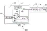
请参照图1,其为本申请一实施例示出的手持清洁设备1中各部件的连接示意图。如图1所示,本申请中的手持清洁设备1包括手持装置10(图1中未示出)、清洁机主体30(图1中未示出)、配件(图1中未示出)、检测电路20及控制模块12。其中,手持装置10上还设有第一按键11,第一按键11可以用于控制手持装置10的启动及关闭,或者,第一按键11可以用于控制手持装置10的工作挡位等。清洁机主体30和配件与手持装置10可拆卸连接,当清洁机主体30与手持装置10相配合时,可实现洗地机功能;当配件与手持装置10相配合时,可实现一般吸尘设备的功能。示例性的,配件可以为尘杯、电动床褥刷及电动地刷等,则此时可以根据吸尘场景的不同,选取相应的配件与手持装置10相配合。控制模块12与检测电路20相连接,控制模块12用于根据检测电路20的信号输出情况及第一按键11的触发情况,确定与手持装置10连接的负载类型,并基于上述负载类型,控制手持装置10工作在不同工作模式。具体的,如图1所示,本实施例中,第一按键11可以通过与检测电路20电连接的方式,与控制模块12间接连接,从而使得控制模块12能够通过硬件的方式对第一按键11的触发情况进行检测。Please refer to FIG. 1 , which is a schematic diagram of connection of various components in a
因本申请中的清洁设备是通过电池组等供电模块15供电的,故为使得供电模块15能长时间处于较好的状态,会在清洁设备处于不工作状态时,使供电模块15处于深度休眠状态;在清洁设备需要进入工作状态时,再将供电模块15从休眠状态唤醒,使供电模块15为清洁设备供电,从而正常执行清洁工作。具体的,唤醒供电模块15的方式为,通过检测电路20输出一唤醒信号至供电模块15中,从而使得供电模块15能够在接收到上述唤醒信号时,由休眠状态被唤醒。其中,因本实施例中的供电模块15与控制模块12是集成在一起的,故此时检测电路20可以通过向控制模块12输出唤醒信号的方式,唤醒供电模块15。Because the cleaning equipment in this application is powered by a
基于此原理,本申请中控制模块12可以基于上述唤醒信号的输出情况及第一按键11的触发情况,确定当前与手持装置10相连接的负载类型,从而基于上述负载类型的不同,控制手持装置10工作在不同的工作模式。进一步的,通过控制手持装置10工作在不同的工作模式,使手持清洁设备1能够根据应用场景的不同,以不同清洁模式进行运转。具体的,当控制模块12检测到检测电路20输出唤醒信号,且在预设时间内未检测到第一按键11被触发时,则可以确定当前与手持装置10连接的负载为清洁机主体30,此时可以控制手持装置10以洗地机模式(第一模式)运转。若控制模块12检测到检测电路20输出唤醒信号,且在预设时间内检测到第一按键11被触发,则可以确定当前与手持装置10连接的负载为配件,此时可以控制手持装置10以吸尘模式(第二模式)运转。示例性的,预设时间可以为5ms~10ms。Based on this principle, the
请参照图2,其为本申请一实施例示出的第一检测电路210的结构示意图。如图2所示,清洁机主体30上设有第二按键31,检测电路20包括设于手持装置10上的第一检测电路210。其中,第二按键31与第一检测电路210电连接,第二按键31可以用于控制清洁机主体30的开启或关闭,或者,第二按键31可以用于控制清洁机主体30的工作模式。第一检测电路210用于在第一按键11或者第二按键31被触发时,输出唤醒信号。Please refer to FIG. 2 , which is a schematic structural diagram of a
如图2所示,本实施例中的第一检测电路210包括第一支路211及第二支路212;其中,第一支路211与控制模块12及第一按键11连接,第二支路212与第二按键31及控制模块12连接,第二支路212与控制模块12及第二按键31连接。第一支路211包括二极管D1及电容C2,二极管D1的阳极与控制模块12连接,二极管D1的阴极与第一按键11连接;电容C2的一端与第一按键11连接,电容C2的另一端接地。第二支路212包括开关元件Q10及稳压二极管DZ1,稳压二极管DZ1的阴极与MOS管的栅极连接,稳压二极管DZ1的阳极接地。示例性的,开关元件Q10可以为MOS管,则此时MOS管的漏极D与控制模块12连接,MOS管的栅极G与第二按键31连接,MOS管的源极S接地。As shown in Figure 2, the
在一实施例中,如图2所示,第一支路211及第二支路212可以通过同一连接端与控制模块12连接,且第一支路211及第二支路212中还可以包括限流电阻R1、限流电阻R2及保护电阻R4。通过设置上述电阻,对电路进行保护。In one embodiment, as shown in FIG. 2 , the
下面结合图2中所示意出的第一检测电路210的结构,详细讲解第一检测电路210输出唤醒信号的原理:The principle of the wake-up signal output by the
当第一按键11被触发时,第一支路211导通,第一检测电路210通过第一支路211输出唤醒信号至控制模块12。当第二按键31被触发时,开关元件Q10导通,第二支路212导通,第一检测电路210通过第二支路212输出唤醒信号至控制模块12。When the
下面结合图2,详细讲解控制模块12驱动手持装置10工作的原理:Below in conjunction with Fig. 2, explain in detail the working principle of the
控制模块12在接收到唤醒信号且识别到第一按键11被触发时,控制手持装置10以吸尘模式运转。控制模块12在接收到唤醒信号且识别到第一按键11未被触发时,控制手持装置10以洗地机模式运转。When the
在另一实施例中,如图3所示,本实施例中,第二按键31可以通过触发电路32与第二支路212间接连接。此时,当第二按键31被触发时,触发电路32输出一电平变化信号,通过此电平变化信号使开关元件Q10导通。In another embodiment, as shown in FIG. 3 , in this embodiment, the
在另一实施例中,如图4所示,本实施例中,控制模块12与供电模块15是分开的,第一检测电路210通过与供电模块15连接的方式,与控制模块12间接连接。此时,控制模块12可以基于供电模块15当前的状态,检测第一检测电路210是否输出唤醒信号。具体的,当控制模块12识别到供电模块15被唤醒时,则可以认为第一检测电路210已经输出了唤醒信号;当控制模块12未识别到供电模块15被唤醒,则可以认为第一检测电路210仍未输出唤醒信号。在获知唤醒信号的输出情况之后,控制模块12即可再基于第一按键11的触发情况,确定手持装置10当前所连接的负载类型。In another embodiment, as shown in FIG. 4 , in this embodiment, the
下面结合图4,详细讲解控制模块12驱动手持装置10工作的原理:Below in conjunction with Fig. 4, explain in detail the working principle of the
控制模块12在检测到供电模块15被唤醒且识别到第一按键11被触发时,控制手持装置10以吸尘模式运转。控制模块12在检测到供电模块15被唤醒且识别到第一按键11未被触发时,控制手持装置10以洗地机模式运转。When the
请参照图5,其为本申请一实施例提供的第二检测电路220的结构示意图。如图5所示,本申请中的检测电路20还包括第二检测电路220;其中,第二检测电路220包括第一连接端13及第二连接端33;第一连接端13设于手持装置10上,且第一连接端13与控制模块12连接;第二连接端33设于清洁机主体30上,用于与第一连接端13连接;第一连接端13连接有一上拉电路,第二连接端33连接有一下拉电路;第二连接端33用于在与第一连接端13连接时,产生电平变化信号。示例性的,如图5所示,上拉电路中可以包括一上拉电阻R5,下拉电路中可以包括一下拉电阻R6。Please refer to FIG. 5 , which is a schematic structural diagram of the
在另一实施例中,第一连接端13可以连接有一下拉电路,第二连接端33可以连接有一上拉电路。In another embodiment, the
下面结合图5及图2,详细讲解控制模块12驱动手持装置10工作的原理:The working principle of the
控制模块12在接收到唤醒信号且识别到第一按键11被触发时,控制手持装置10以吸尘模式运转。控制模块12在接收到唤醒信号、电平变化信号且在预设时间内未识别到第一按键11被触发时,控制手持装置10以洗地机模式运转。When the
通过上述措施,使得控制模块12在同时接收到唤醒信号及电平变化信号后,再控制手持装置10以洗地机模式运转,充分保证了负载类型识别的准确性。Through the above measures, the
请参照图6,其为本申请一实施例示出的清洁机主体30与手持装置10的连接示意图。如图6所示,本实施例中,第二连接端33与控制模块12连接,第一连接端13设置在控制模块12上且与第一支路211的输出端连接。示例性的,如图3所示,此时第一连接端13可以位于图中的WKUP位置。Please refer to FIG. 6 , which is a schematic diagram of the connection between the cleaning machine
在本实施例中,当手持装置10与清洁机主体30连接时,第二连接端33可以直接输出唤醒信号至控制模块12;当手持装置10与配件连接时,可以通过触发第一按键11的方式,由第一连接端13输出唤醒信号至控制模块12。基于此,控制模块12可以通过判断唤醒信号是由第一连接端13还是第二连接端33输出的,确定手持装置10当前所连接的负载类型。In this embodiment, when the
值得注意的是,本实施例与图2中所示实施例的区别在于,本实施例中无需检测第一按键11是否被触发,只需检测唤醒信号是由第一连接端13还是第二连接端33输出的,即可确定手持装置10当前所连接的负载类型,识别方式简单。It should be noted that the difference between this embodiment and the embodiment shown in FIG. 2 is that in this embodiment, it is not necessary to detect whether the
请参照图7,其为本申请另一实施例示出的清洁机主体30与手持装置10的连接示意图。如图7所示,本实施例与图2中所示实施例的区别在于,本实施例中,手持清洁设备1还包括第三连接端14;第三连接端14设于手持装置10上,且与第二按键31及控制模块12连接,用于在第二按键31被触发时输出检测信号;其中,检测信号为一高低电平变化信号。Please refer to FIG. 7 , which is a schematic diagram of the connection between the cleaning machine
本实施例中,当手持装置10与清洁机主体30连接时,第三连接端14能够在第二按键31被触发时,输出检测信号至控制模块12,从而使得控制模块12能够在接收到上述检测信号后有效识别出位于清洁机主体30上的第二按键31被触发。进一步的,使得控制模块12能够在检测到第二按键31被触发及检测到第一检测电路210输出唤醒信号时,控制手持装置10以洗地机模式运转。其中,在手持装置10运转的同时,手持装置10给清洁机主体30供电,并通过清洁机主体30中的电控模块通讯电路,发送上述按键信息给清洁机主体,使清洁机主体30能够正确的响应上述按键指令。In this embodiment, when the
下面结合图7及图2,详细讲解控制模块12驱动手持装置10工作的原理:The working principle of the
控制模块12在接收到唤醒信号且识别到第一按键11被触发时,控制手持装置10以吸尘模式运转。控制模块12在接收到唤醒信号、检测到第二按键被触发且在预设时间内未识别到第一按键11被触发时,控制手持装置10以洗地机模式运转。When the
基于上述多个实施例可以看出,本申请中提供的手持清洁设备1包括手持装置10、清洁机主体30、配件、检测电路20、控制模块12及第一按键11;其中,控制模块12可以通过检测电路20的信号输出情况及第一按键11的触发情况,确定当前连接在手持装置10上的负载类型,从而最终基于不同的负载类型,控制手持装置10工作在不同的清洁模式。进一步的,通过控制手持装置10工作在不同的工作模式,使手持清洁设备1能够根据应用场景的不同,以不同清洁模式进行运转,这极大地提升了清洁设备的利用率,拓展了清洁设备的应用场景,提升了产品竞争力。Based on the above-mentioned multiple embodiments, it can be seen that the
在一实施例中,在手持清洁设备1工作的过程中,控制模块12还可以基于手持装置10的工作电流,判定手持装置10连接的负载类型。基于负载类型确定是否要对当前的负载供电,在不需要进行供电时,进行断电操作;在需要进行供电时,基于手持装置10当前的工作电流,为手持装置10设定相应的电流保护参数,从而通过此操作对负载进行保护。其中,各负载类型的电流保护参数的对应关系如表1所示。In an embodiment, during the working process of the
表1负载类型与电流保护参数对照表Table 1 Comparison Table of Load Type and Current Protection Parameters

以上所述仅为本申请的优选实施例而已,并不用于限制本申请,对于本领域的技术人员来说,本申请可以有各种更改和变化。凡在本申请的精神和原则之内,所作的任何修改、等同替换、改进等,均应包含在本申请的保护范围之内。The above descriptions are only preferred embodiments of the present application, and are not intended to limit the present application. For those skilled in the art, there may be various modifications and changes in the present application. Any modifications, equivalent replacements, improvements, etc. made within the spirit and principles of this application shall be included within the protection scope of this application.
Claims (10)
Priority Applications (1)
| Application Number | Priority Date | Filing Date | Title |
|---|---|---|---|
| CN202211093630.9ACN116115113A (en) | 2022-09-08 | 2022-09-08 | A handheld cleaning device |
Applications Claiming Priority (1)
| Application Number | Priority Date | Filing Date | Title |
|---|---|---|---|
| CN202211093630.9ACN116115113A (en) | 2022-09-08 | 2022-09-08 | A handheld cleaning device |
Publications (1)
| Publication Number | Publication Date |
|---|---|
| CN116115113Atrue CN116115113A (en) | 2023-05-16 |
Family
ID=86296140
Family Applications (1)
| Application Number | Title | Priority Date | Filing Date |
|---|---|---|---|
| CN202211093630.9APendingCN116115113A (en) | 2022-09-08 | 2022-09-08 | A handheld cleaning device |
Country Status (1)
| Country | Link |
|---|---|
| CN (1) | CN116115113A (en) |
Citations (18)
| Publication number | Priority date | Publication date | Assignee | Title |
|---|---|---|---|---|
| JPH07255654A (en)* | 1994-03-18 | 1995-10-09 | Hitachi Ltd | Vacuum cleaner |
| JP2004105273A (en)* | 2002-09-13 | 2004-04-08 | Matsushita Electric Ind Co Ltd | Rechargeable vacuum cleaner |
| US20100256812A1 (en)* | 2008-08-08 | 2010-10-07 | Yuko Tsusaka | Control device and control method for cleaner, cleaner, control program for cleaner, and integrated electronic circuit |
| KR20130012519A (en)* | 2011-07-25 | 2013-02-04 | 엘지전자 주식회사 | Robot cleaner and self testing method of the same |
| JP2013132510A (en)* | 2011-12-27 | 2013-07-08 | Toshiba Corp | Vacuum cleaner |
| JP2015097663A (en)* | 2013-11-19 | 2015-05-28 | アイリスオーヤマ株式会社 | Handy type vacuum cleaner and control method of the same |
| US20180177363A1 (en)* | 2015-06-02 | 2018-06-28 | Kingclean Electric Co., Ltd. | Rod handheld two-in-one split-type vacuum cleaner having independent dust-air separation and dust storage device |
| CN109464063A (en)* | 2018-12-10 | 2019-03-15 | 江苏美的清洁电器股份有限公司 | Cleaning equipment |
| US20190090702A1 (en)* | 2017-09-27 | 2019-03-28 | Ningbo Shijia Cleaning Tools Co.,Ltd. | Intelligent dust mop |
| CN211862680U (en)* | 2020-03-19 | 2020-11-06 | 佛山市优一家电制造有限公司 | Multi-mode cleaning device |
| CN112367070A (en)* | 2020-10-30 | 2021-02-12 | 武汉优炜星科技有限公司 | Key control method for handheld device |
| CN112826370A (en)* | 2020-12-31 | 2021-05-25 | 添可智能科技有限公司 | Working method and power source |
| CN113273937A (en)* | 2021-06-01 | 2021-08-20 | 深圳市银舍创新科技有限公司 | Cleaning device capable of being applied to multiple scenes |
| CN215016867U (en)* | 2021-05-27 | 2021-12-07 | 莱克电气股份有限公司 | Vacuuming, cleaning, handheld three-in-one dry and wet dual-use multi-functional handheld stick vacuum cleaner |
| CN114098551A (en)* | 2021-02-06 | 2022-03-01 | 曲阜信多达智能科技有限公司 | Cleaning machine system |
| CN215937267U (en)* | 2021-09-15 | 2022-03-04 | 追觅创新科技(苏州)有限公司 | Cleaning device |
| CN216262266U (en)* | 2020-09-30 | 2022-04-12 | 苏州宝时得电动工具有限公司 | Steam cleaning machine |
| CN217137940U (en)* | 2021-12-30 | 2022-08-09 | 尚科宁家(中国)科技有限公司 | Surface cleaning device with reliable structure |
- 2022
- 2022-09-08CNCN202211093630.9Apatent/CN116115113A/enactivePending
Patent Citations (18)
| Publication number | Priority date | Publication date | Assignee | Title |
|---|---|---|---|---|
| JPH07255654A (en)* | 1994-03-18 | 1995-10-09 | Hitachi Ltd | Vacuum cleaner |
| JP2004105273A (en)* | 2002-09-13 | 2004-04-08 | Matsushita Electric Ind Co Ltd | Rechargeable vacuum cleaner |
| US20100256812A1 (en)* | 2008-08-08 | 2010-10-07 | Yuko Tsusaka | Control device and control method for cleaner, cleaner, control program for cleaner, and integrated electronic circuit |
| KR20130012519A (en)* | 2011-07-25 | 2013-02-04 | 엘지전자 주식회사 | Robot cleaner and self testing method of the same |
| JP2013132510A (en)* | 2011-12-27 | 2013-07-08 | Toshiba Corp | Vacuum cleaner |
| JP2015097663A (en)* | 2013-11-19 | 2015-05-28 | アイリスオーヤマ株式会社 | Handy type vacuum cleaner and control method of the same |
| US20180177363A1 (en)* | 2015-06-02 | 2018-06-28 | Kingclean Electric Co., Ltd. | Rod handheld two-in-one split-type vacuum cleaner having independent dust-air separation and dust storage device |
| US20190090702A1 (en)* | 2017-09-27 | 2019-03-28 | Ningbo Shijia Cleaning Tools Co.,Ltd. | Intelligent dust mop |
| CN109464063A (en)* | 2018-12-10 | 2019-03-15 | 江苏美的清洁电器股份有限公司 | Cleaning equipment |
| CN211862680U (en)* | 2020-03-19 | 2020-11-06 | 佛山市优一家电制造有限公司 | Multi-mode cleaning device |
| CN216262266U (en)* | 2020-09-30 | 2022-04-12 | 苏州宝时得电动工具有限公司 | Steam cleaning machine |
| CN112367070A (en)* | 2020-10-30 | 2021-02-12 | 武汉优炜星科技有限公司 | Key control method for handheld device |
| CN112826370A (en)* | 2020-12-31 | 2021-05-25 | 添可智能科技有限公司 | Working method and power source |
| CN114098551A (en)* | 2021-02-06 | 2022-03-01 | 曲阜信多达智能科技有限公司 | Cleaning machine system |
| CN215016867U (en)* | 2021-05-27 | 2021-12-07 | 莱克电气股份有限公司 | Vacuuming, cleaning, handheld three-in-one dry and wet dual-use multi-functional handheld stick vacuum cleaner |
| CN113273937A (en)* | 2021-06-01 | 2021-08-20 | 深圳市银舍创新科技有限公司 | Cleaning device capable of being applied to multiple scenes |
| CN215937267U (en)* | 2021-09-15 | 2022-03-04 | 追觅创新科技(苏州)有限公司 | Cleaning device |
| CN217137940U (en)* | 2021-12-30 | 2022-08-09 | 尚科宁家(中国)科技有限公司 | Surface cleaning device with reliable structure |
Similar Documents
| Publication | Publication Date | Title |
|---|---|---|
| EP3654810B1 (en) | Vacuum cleaner and control method thereof | |
| US5353468A (en) | Vacuum cleaner comprising a suction tube and suction tube provided with a remote-control circuit comprising a capacitive sensor | |
| JP2013168386A (en) | Standby power cut-off device and control method therefor | |
| KR20190016795A (en) | Vacuum cleaner and controlling method of the vacuum cleaner | |
| JP5728220B2 (en) | Power supply interruption device | |
| CN116115113A (en) | A handheld cleaning device | |
| JP6741734B2 (en) | Battery powered vacuum cleaner | |
| CN102280021A (en) | Infrared remote control switch | |
| KR20060034851A (en) | Wired / Wireless Vacuum Cleaner | |
| JP6294102B2 (en) | Battery-powered electronics | |
| JP6195783B2 (en) | Battery-powered electronics | |
| CN213693665U (en) | Touch sliding switch circuit and display card | |
| JP6446664B2 (en) | Electric vacuum cleaner | |
| KR100559946B1 (en) | Power Management Device and Method | |
| CN208211979U (en) | A kind of sweeping robot | |
| CN112713888A (en) | Touch sliding switch circuit and display card | |
| CN214782697U (en) | Washing machine power supply circuit and washing machine | |
| JP6417489B2 (en) | Battery-powered electronics | |
| CN218356051U (en) | Interlock protection circuit and cleaning equipment | |
| CN222674293U (en) | Pulse reset circuit and electronic equipment | |
| CN220024933U (en) | Cleaning system | |
| CN109532027A (en) | 3D printer soft-off control circuit and 3D printing equipment | |
| CN217610826U (en) | Zero-power-consumption standby circuit of floor sweeping and mopping robot | |
| CN210323856U (en) | A no-power-consumption power supply circuit | |
| EP1455262A2 (en) | Electric device with power stoppage detection |
Legal Events
| Date | Code | Title | Description |
|---|---|---|---|
| PB01 | Publication | ||
| PB01 | Publication | ||
| SE01 | Entry into force of request for substantive examination | ||
| SE01 | Entry into force of request for substantive examination |