CN116111535A - Cable clamp for cable installation - Google Patents
Cable clamp for cable installationDownload PDFInfo
- Publication number
- CN116111535A CN116111535ACN202310402040.8ACN202310402040ACN116111535ACN 116111535 ACN116111535 ACN 116111535ACN 202310402040 ACN202310402040 ACN 202310402040ACN 116111535 ACN116111535 ACN 116111535A
- Authority
- CN
- China
- Prior art keywords
- cable
- plate
- fixedly connected
- rod
- splint
- Prior art date
- Legal status (The legal status is an assumption and is not a legal conclusion. Google has not performed a legal analysis and makes no representation as to the accuracy of the status listed.)
- Granted
Links
Images


Classifications
- H—ELECTRICITY
- H02—GENERATION; CONVERSION OR DISTRIBUTION OF ELECTRIC POWER
- H02G—INSTALLATION OF ELECTRIC CABLES OR LINES, OR OF COMBINED OPTICAL AND ELECTRIC CABLES OR LINES
- H02G3/00—Installations of electric cables or lines or protective tubing therefor in or on buildings, equivalent structures or vehicles
- H02G3/30—Installations of cables or lines on walls, floors or ceilings
- H02G3/32—Installations of cables or lines on walls, floors or ceilings using mounting clamps
- Y—GENERAL TAGGING OF NEW TECHNOLOGICAL DEVELOPMENTS; GENERAL TAGGING OF CROSS-SECTIONAL TECHNOLOGIES SPANNING OVER SEVERAL SECTIONS OF THE IPC; TECHNICAL SUBJECTS COVERED BY FORMER USPC CROSS-REFERENCE ART COLLECTIONS [XRACs] AND DIGESTS
- Y02—TECHNOLOGIES OR APPLICATIONS FOR MITIGATION OR ADAPTATION AGAINST CLIMATE CHANGE
- Y02E—REDUCTION OF GREENHOUSE GAS [GHG] EMISSIONS, RELATED TO ENERGY GENERATION, TRANSMISSION OR DISTRIBUTION
- Y02E10/00—Energy generation through renewable energy sources
- Y02E10/50—Photovoltaic [PV] energy
Landscapes
- Engineering & Computer Science (AREA)
- Architecture (AREA)
- Civil Engineering (AREA)
- Structural Engineering (AREA)
- Laying Of Electric Cables Or Lines Outside (AREA)
- Suspension Of Electric Lines Or Cables (AREA)
Abstract
Translated fromChinese
Description
Translated fromChinese技术领域technical field
本发明涉及电缆固定机构领域,尤其涉及一种电缆安装用电缆夹具。The invention relates to the field of cable fixing mechanisms, in particular to a cable clamp for cable installation.
背景技术Background technique
电缆夹具用来固定铺设的电缆,在房顶等平面铺设电缆时,通过夹具将电缆夹持固定,每间隔一端距离进行电缆的夹持固定,并且夹具通过栓件固定安装在安装面,但是由于仅仅通过栓件进行安装面的加固,在长久使用后,螺栓位置易发生松动的问题,尤其是后期发生腐蚀生锈等问题后,松动问题尤为明显,这就使得电缆的铺设不够稳定,另外的,在实际施工中,电缆的铺设并非为水平一条直线的铺设,经常会存在弯曲的位置,该位置通常需要夹具的进行加固,是加固的重点位,而由于电缆的弯曲,使得电缆与夹具间所成弯曲程度较大,长久使用后,易造成电缆破裂等问题发生。The cable clamp is used to fix the laid cable. When laying the cable on the roof and other planes, the cable is clamped and fixed by the clamp, and the cable is clamped and fixed at each end distance, and the clamp is fixed on the installation surface by a bolt. However, due to Only bolts are used to reinforce the mounting surface. After long-term use, the bolt position is prone to loosening, especially after corrosion and rust in the later stage, the loosening problem is particularly obvious, which makes the laying of cables not stable enough. , in actual construction, the laying of the cable is not a horizontal and straight line, and there is often a bent position, which usually needs to be reinforced by the fixture, which is the key point of reinforcement, and due to the bending of the cable, the distance between the cable and the fixture The degree of bending is relatively large, and after long-term use, it is easy to cause problems such as cable breakage.
发明内容Contents of the invention
本发明的目的是为了解决背景技术中存在的缺点,而提出的一种电缆安装用电缆夹具。The object of the present invention is to propose a cable clamp for cable installation in order to solve the shortcomings in the background technology.
为达到以上目的,本发明采用的技术方案为:一种电缆安装用电缆夹具,包括下夹板与上夹板,所述下夹板与上夹板的两侧边通过锁紧件进行固定,所述上夹板的上表面设置有两个中心对称的稳固环件,所述下夹板的下表面通过调距机构活动安装有底板,所述下夹板的下表面转动嵌装有若干个转动杆,所述底板的上表面靠近两边处贯穿设置有锚固杆;In order to achieve the above purpose, the technical solution adopted by the present invention is: a cable clamp for cable installation, including a lower splint and an upper splint, the two sides of the lower splint and the upper splint are fixed by locking pieces, and the upper splint The upper surface of the upper surface of the lower splint is provided with two center-symmetric stable rings, the lower surface of the lower splint is movably installed with a bottom plate through the distance adjustment mechanism, the lower surface of the lower splint is rotatably embedded with several rotating rods, and the bottom surface of the bottom splint Anchor rods are provided through the upper surface near both sides;
所述下夹板与上夹板夹持电缆后,两侧的稳固环件分别夹持住电缆的表面,对电缆出下夹板与上夹板之间处的弯曲弧度进行降低;After the cable is clamped by the lower splint and the upper splint, the stable rings on both sides respectively clamp the surface of the cable to reduce the bending arc of the cable between the lower splint and the upper splint;
所述转动杆转下后于底板与地面之间浇筑混凝土,混凝土凝固后转动杆位于内部。After the rotating rod is rotated down, concrete is poured between the bottom plate and the ground, and the rotating rod is located inside after the concrete is solidified.
优选的,所述锁紧件分别包括固定连接在上夹板与下夹板两边的延伸板,位于下方的所述延伸板的上表面固定连接有锁紧螺栓,所述锁紧螺栓滑动贯穿上方的延伸板且在端部套设有锁紧螺母,所述锁紧螺母与锁紧螺栓螺纹配合。Preferably, the locking parts respectively include extension plates fixedly connected to both sides of the upper splint and the lower splint, and the upper surface of the lower extension plate is fixedly connected with a locking bolt, and the locking bolt slides through the upper extension The plate is provided with a locking nut at the end, and the locking nut is threadedly matched with the locking bolt.
优选的,所述上夹板与下夹板的内壁上分别固定设置有软质垫,所述软质垫为橡胶材质。Preferably, the inner walls of the upper splint and the lower splint are respectively fixed with soft pads, and the soft pads are made of rubber.
优选的,所述稳固环件包括固定设置上夹板上表面的螺纹筒,所述螺纹筒的一端插装有相互螺纹配合的螺纹杆,所述螺纹杆的外表面滑动插装有插条,所述螺纹杆的一端贯穿设置有螺纹配合的旋动头,所述旋动头的端部抵在插条的表面,所述插条的一端设置有卡箍件。Preferably, the stabilizing ring includes a threaded cylinder fixedly arranged on the upper surface of the upper splint, one end of the threaded cylinder is inserted with a threaded rod that is threaded with each other, and the outer surface of the threaded rod is slidably inserted with an insertion strip, so One end of the threaded rod is penetrated with a threaded rotating head, and the end of the rotating head is against the surface of the insert, and one end of the insert is provided with a hoop.
优选的,所述卡箍件包括固定连接在插条一端的下夹环、一端与下夹环一端转动连接的上夹环,所述上夹环的另一端固定连接有上板,所述下夹环的另一端固定连接有下板,所述上板与下板之间通过螺固件进行连接。Preferably, the hoop includes a lower clamp ring fixedly connected to one end of the insertion strip, and an upper clamp ring rotatably connected to one end of the lower clamp ring, the other end of the upper clamp ring is fixedly connected to an upper plate, and the lower clamp ring The other end of the clamp ring is fixedly connected with the lower plate, and the upper plate and the lower plate are connected by screws.
优选的,所述螺固件包括通过转轴来与下板转动连接的转动块,所述转动块的上表面固定连接有限位栓,所述限位栓活动穿过上板且端部套设有螺纹配合的限位螺母。Preferably, the screw includes a rotating block that is rotatably connected to the lower plate through a rotating shaft, the upper surface of the rotating block is fixedly connected with a limit bolt, and the limit bolt moves through the upper plate and the end is sleeved with threads Fitting stop nut.
优选的,所述调距机构包括固定设置在底板上表面的两个第一固定座以及两个第二固定座,两个所述第一固定座之间固定连接有导杆,两个所述第二固定座之间转动连接有丝杆,所述丝杆的一端固定连接有旋柄,所述下夹板的下表面固定连接有滑座,所述滑座与导杆滑动配合,所述滑座与丝杆螺纹配合。Preferably, the distance adjustment mechanism includes two first fixed seats and two second fixed seats fixedly arranged on the upper surface of the bottom plate, a guide rod is fixedly connected between the two first fixed seats, and two described A threaded rod is rotatably connected between the second fixed seats, one end of the threaded rod is fixedly connected with a handle, the lower surface of the lower splint is fixedly connected with a sliding seat, and the sliding seat is slidably matched with the guide rod. The seat is matched with the screw thread.
优选的,所述转动杆设置为两组且分别位于底板以下的两侧处,位于一侧的一组所述转动杆的端部共同固定连接有连接轴,所述连接轴与藏入槽相转动配合,所述底板的下表面靠近中间位置处滑动设置有两个滑动条,所述滑动条的一侧凸设有若干个挡块,所述挡块拖住转动杆的下表面。Preferably, the rotating rods are set in two groups and are respectively located on both sides below the bottom plate, and the ends of a group of rotating rods located on one side are jointly fixedly connected with a connecting shaft, and the connecting shaft is connected to the storage groove. Rotational fit, the lower surface of the bottom plate is slidably provided near the middle position with two sliding bars, and a side of the sliding bar is protrudingly provided with several stoppers, and the stoppers drag the lower surface of the rotating rod.
优选的,所述底板的下表面靠近两个滑动条之间处转动连接有旋动柱,所述旋动柱的外表面固定设置有转动齿,所述滑动条的侧面设置有若干个凸齿,所述转动齿与凸齿相啮合,所述底板的前后边固定连接有导板,所述滑动条的端部与导板滑动配合。Preferably, the lower surface of the bottom plate is rotatably connected with a rotating column close to the place between the two sliding bars, the outer surface of the rotating column is fixedly provided with rotating teeth, and the side of the sliding bar is provided with several protruding teeth , the rotating teeth are meshed with the protruding teeth, the front and rear sides of the bottom plate are fixedly connected with guide plates, and the ends of the sliding bars are slidingly matched with the guide plates.
优选的,所述锚固杆的外表面固定设置有支撑板,所述锚固杆的上端固定连接有敲击头。Preferably, the outer surface of the anchor rod is fixedly provided with a support plate, and the upper end of the anchor rod is fixedly connected with a striking head.
与现有技术相比,本发明具有以下有益效果:Compared with the prior art, the present invention has the following beneficial effects:
1、该夹具在固定时出来锚固之外,还具备混凝土加固的方式,具备较好的安装稳定性,可以有效避免弯曲处弯曲过大而发生损坏的问题。1. In addition to being anchored when fixed, the fixture also has a concrete reinforcement method, which has better installation stability and can effectively avoid damage caused by excessive bending at the bend.
2、在旋下锁紧螺母后,可以将上夹板取下,从而将电缆经过上夹板与下夹板之间,之后再旋紧锁紧螺母,保障电缆夹紧的稳定,之后旋下限位螺母后,可以将限位栓从上板处移出,之后即可将下夹环与上夹环夹在电缆表面,之后再度旋上限位螺母,通过旋松旋动头后,可以将插条移动,即控制电缆从上夹板与下夹板经过后出来时的弯曲程度,使得电缆在弯曲铺设的过程中,固定位置的弯曲存在平缓的过渡带,从而表面了固定点电缆长久使用后损坏的问题发生。2. After unscrewing the lock nut, the upper splint can be removed, so that the cable passes between the upper splint and the lower splint, and then the lock nut is tightened to ensure the stability of the cable clamping, and then the limit nut is unscrewed , the limit bolt can be removed from the upper plate, and then the lower clamp ring and the upper clamp ring can be clamped on the surface of the cable, and then the upper limit nut can be screwed again, and the insert can be moved by loosening the screw head, that is, Control the bending degree of the cable when it passes through the upper splint and the lower splint, so that during the bending and laying process of the cable, there is a gentle transition zone in the bending of the fixed position, thus avoiding the problem of damage to the fixed point cable after long-term use.
3、在将底板固定在安装面处时,将锚固杆插入至安装面,直至到支撑板贴紧在安装面的表面时停止,再之后转动旋动柱,在转动齿与凸齿的配合下,使得两侧的滑动条移动,进而使得挡块移开,不再托举住转动杆,转动杆向下转动后,直至下端接触到安装面,之后向着底板与安装面之间填入混凝土,带混凝土冷却后完成加固,而内部由于转动杆的存在,起到了增加混凝土处强度的功能,因此,该夹具安装布置后更为稳定。3. When fixing the bottom plate on the installation surface, insert the anchor rod to the installation surface until the support plate is close to the surface of the installation surface and stop, then turn the rotating column, under the cooperation of the rotating teeth and the convex teeth , so that the sliding bars on both sides move, and then the stoppers are removed, and the rotating rod is no longer held. After the rotating rod is rotated downward, until the lower end touches the installation surface, concrete is filled between the bottom plate and the installation surface. The reinforcement is completed after the concrete is cooled, and because of the existence of the rotating rod inside, it has the function of increasing the strength of the concrete. Therefore, the fixture is more stable after installation.
4、通过转动旋柄,可以使得丝杆转动,进而可以使得滑座发生平移,配合两侧处下夹环与上夹环的配合,可以改变该段电缆的弯曲程度,从而完成电缆的弯曲铺设,减少该节点位置电缆的损坏问题。4. By turning the rotary handle, the screw rod can be rotated, and then the sliding seat can be translated. With the cooperation of the lower clamp ring and the upper clamp ring on both sides, the bending degree of the cable can be changed, so as to complete the bending laying of the cable , to reduce damage to the cable at the node.
附图说明Description of drawings
图1为本发明一种电缆安装用电缆夹具的结构示意图;Fig. 1 is a structural representation of a cable clamp for cable installation of the present invention;
图2为本发明一种电缆安装用电缆夹具的局部结构示意图;Fig. 2 is a partial structural schematic diagram of a cable clamp for cable installation of the present invention;
图3为本发明一种电缆安装用电缆夹具的底板处示意图;Fig. 3 is a schematic diagram of the bottom plate of a cable clamp for cable installation of the present invention;
图4为本发明一种电缆安装用电缆夹具的底板下方视角示意图;Fig. 4 is a schematic diagram of a view from the bottom of the bottom plate of a cable clamp for cable installation according to the present invention;
图5为本发明一种电缆安装用电缆夹具的图4中A处放大图;Fig. 5 is an enlarged view of A in Fig. 4 of a cable clamp for cable installation according to the present invention;
图6为本发明一种电缆安装用电缆夹具的底板处剖视图;Fig. 6 is a sectional view at the bottom plate of a cable clamp for cable installation according to the present invention;
图7为本发明一种电缆安装用电缆夹具的图6中B处放大图;Fig. 7 is an enlarged view of B in Fig. 6 of a cable clamp for cable installation according to the present invention;
图8为本发明一种电缆安装用电缆夹具的稳固环件处示意图;Fig. 8 is a schematic diagram of a stable ring part of a cable clamp for cable installation according to the present invention;
图9为本发明一种电缆安装用电缆夹具的图8中C处放大图。Fig. 9 is an enlarged view of C in Fig. 8 of a cable clamp for cable installation according to the present invention.
1、下夹板;2、上夹板;3、软质垫;4、延伸板;5、锁紧螺栓;6、锁紧螺母;7、底板;8、滑座;9、第一固定座;10、导杆;11、第二固定座;12、丝杆;13、旋柄;14、藏入槽;15、转动杆;16、连接轴;17、滑动条;18、挡块;19、旋动柱;20、转动齿;21、凸齿;22、导板;23、锚固杆;24、敲击头;25、支撑板;26、螺纹筒;27、螺纹杆;28、插条;29、旋动头;30、下夹环;31、上夹环;32、下板;33、转动块;34、转轴;35、上板;36、限位栓;37、限位螺母。1. Lower splint; 2. Upper splint; 3. Soft cushion; 4. Extension plate; 5. Locking bolt; 6. Locking nut; 7. Bottom plate; 8. Sliding seat; 9. First fixed seat; 10 , guide rod; 11, second fixed seat; 12, screw rod; 13, rotating handle; 14, hiding in the groove; 15, rotating rod; 16, connecting shaft; 17, sliding bar; 18, block; 19, rotating Moving column; 20, rotating tooth; 21, convex tooth; 22, guide plate; 23, anchor rod; 24, knocking head; 25, support plate; 30, lower clamp ring; 31, upper clamp ring; 32, lower plate; 33, rotating block; 34, rotating shaft; 35, upper plate; 36, limit bolt; 37, limit nut.
具体实施方式Detailed ways
以下描述用于揭露本发明以使本领域技术人员能够实现本发明。以下描述中的优选实施例只作为举例,本领域技术人员可以想到其他显而易见的变型。The following description serves to disclose the present invention to enable those skilled in the art to carry out the present invention. The preferred embodiments described below are only examples, and those skilled in the art can devise other obvious variations.
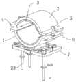
如图1-图9所示的一种电缆安装用电缆夹具,包括下夹板1与上夹板2,下夹板1与上夹板2的两侧边通过锁紧件进行固定,上夹板2的上表面设置有两个中心对称的稳固环件,下夹板1的下表面通过调距机构活动安装有底板7,下夹板1的下表面转动嵌装有若干个转动杆15,底板7的上表面靠近两边处贯穿设置有锚固杆23;A cable clamp for cable installation as shown in Figures 1-9, including a
下夹板1与上夹板2夹持电缆后,两侧的稳固环件分别夹持住电缆的表面,对电缆出下夹板1与上夹板2之间处的弯曲弧度进行降低;After the
转动杆15转下后于底板7与地面之间浇筑混凝土,混凝土凝固后转动杆15位于内部。Concrete is poured between the
该夹具在固定时出来锚固之外,还具备混凝土加固的方式,具备较好的安装稳定性,可以有效避免弯曲处弯曲过大而发生损坏的问题。In addition to being anchored when fixed, the fixture also has a concrete reinforcement method, which has better installation stability and can effectively avoid damage caused by excessive bending at the bend.
锁紧件分别包括固定连接在上夹板2与下夹板1两边的延伸板4,位于下方的延伸板4的上表面固定连接有锁紧螺栓5,锁紧螺栓5滑动贯穿上方的延伸板4且在端部套设有锁紧螺母6,锁紧螺母6与锁紧螺栓5螺纹配合。The locking parts respectively include
上夹板2与下夹板1的内壁上分别固定设置有软质垫3,软质垫3为橡胶材质,起到保护电缆表面的作用。
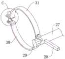
稳固环件包括固定设置上夹板2上表面的螺纹筒26,螺纹筒26的一端插装有相互螺纹配合的螺纹杆27,螺纹杆27的外表面滑动插装有插条28,螺纹杆27的一端贯穿设置有螺纹配合的旋动头29,旋动头29的端部抵在插条28的表面,插条28的一端设置有卡箍件。The stable ring includes a threaded
卡箍件包括固定连接在插条28一端的下夹环30、一端与下夹环30一端转动连接的上夹环31,上夹环31的另一端固定连接有上板35,下夹环30的另一端固定连接有下板32,上板35与下板32之间通过螺固件进行连接。螺固件包括通过转轴34来与下板32转动连接的转动块33,转动块33的上表面固定连接有限位栓36,限位栓36活动穿过上板35且端部套设有螺纹配合的限位螺母37。The hoop piece includes a
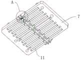
调距机构包括固定设置在底板7上表面的两个第一固定座9以及两个第二固定座11,两个第一固定座9之间固定连接有导杆10,两个第二固定座11之间转动连接有丝杆12,丝杆12的一端固定连接有旋柄13,下夹板1的下表面固定连接有滑座8,滑座8与导杆10滑动配合,滑座8与丝杆12螺纹配合,导杆10用来增加滑座8平移时的稳定性。The distance adjustment mechanism includes two first
转动杆15设置为两组且分别位于底板7以下的两侧处,位于一侧的一组转动杆15的端部共同固定连接有连接轴16,连接轴16与藏入槽14相转动配合,底板7的下表面靠近中间位置处滑动设置有两个滑动条17,滑动条17的一侧凸设有若干个挡块18,挡块18拖住转动杆15的下表面,防止转动杆15直接转下。The
底板7的下表面靠近两个滑动条17之间处转动连接有旋动柱19,旋动柱19的外表面固定设置有转动齿20,滑动条17的侧面设置有若干个凸齿21,转动齿20与凸齿21相啮合,底板7的前后边固定连接有导板22,滑动条17的端部与导板22滑动配合。The lower surface of the
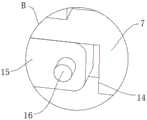
锚固杆23的外表面固定设置有支撑板25,锚固杆23的上端固定连接有敲击头24,用来将锚固杆23打入安装面。The outer surface of the
使用时,在旋下锁紧螺母6后,可以将上夹板2取下,从而将电缆经过上夹板2与下夹板1之间,之后再旋紧锁紧螺母6,保障电缆夹紧的稳定,之后旋下限位螺母37后,可以将限位栓36从上板35处移出,之后即可将下夹环30与上夹环31夹在电缆表面,之后再度旋上限位螺母37,通过旋松旋动头29后,可以将插条28移动,即控制电缆从上夹板2与下夹板1经过后出来时的弯曲程度,使得电缆在弯曲铺设的过程中,固定位置的弯曲存在平缓的过渡带,从而表面了固定点电缆长久使用后损坏的问题发生。在将底板7固定在安装面处时,将锚固杆23插入至安装面,直至到支撑板25贴紧在安装面的表面时停止,再之后转动旋动柱19,在转动齿20与凸齿21的配合下,使得两侧的滑动条17移动,进而使得挡块18移开,不再托举住转动杆15,转动杆15向下转动后,直至下端接触到安装面,之后向着底板7与安装面之间填入混凝土,带混凝土冷却后完成加固,而内部由于转动杆15的存在,起到了增加混凝土处强度的功能,因此,该夹具安装布置后更为稳定。通过转动旋柄13,可以使得丝杆12转动,进而可以使得滑座8发生平移,配合两侧处下夹环30与上夹环31的配合,可以改变该段电缆的弯曲程度,从而完成电缆的弯曲铺设,减少该节点位置电缆的损坏问题。When in use, after unscrewing the
以上显示和描述了本发明的基本原理、主要特征和本发明的优点。本行业的技术人员应该了解,本发明不受上述实施例的限制,上述实施例和说明书中描述的只是本发明的原理,在不脱离本发明精神和范围的前提下本发明还会有各种变化和改进,这些变化和改进都落入要求保护的本发明的范围内。本发明要求的保护范围由所附的权利要求书及其等同物界定。The basic principles, main features and advantages of the present invention have been shown and described above. Those skilled in the art should understand that the present invention is not limited by the above-mentioned embodiments. What are described in the above-mentioned embodiments and the description are only the principles of the present invention. Variations and improvements, which fall within the scope of the claimed invention. The scope of protection required by the present invention is defined by the appended claims and their equivalents.
Claims (10)
Priority Applications (1)
| Application Number | Priority Date | Filing Date | Title |
|---|---|---|---|
| CN202310402040.8ACN116111535B (en) | 2023-04-17 | 2023-04-17 | Cable clamp for cable installation |
Applications Claiming Priority (1)
| Application Number | Priority Date | Filing Date | Title |
|---|---|---|---|
| CN202310402040.8ACN116111535B (en) | 2023-04-17 | 2023-04-17 | Cable clamp for cable installation |
Publications (2)
| Publication Number | Publication Date |
|---|---|
| CN116111535Atrue CN116111535A (en) | 2023-05-12 |
| CN116111535B CN116111535B (en) | 2023-07-28 |
Family
ID=86264199
Family Applications (1)
| Application Number | Title | Priority Date | Filing Date |
|---|---|---|---|
| CN202310402040.8AExpired - Fee RelatedCN116111535B (en) | 2023-04-17 | 2023-04-17 | Cable clamp for cable installation |
Country Status (1)
| Country | Link |
|---|---|
| CN (1) | CN116111535B (en) |
Cited By (2)
| Publication number | Priority date | Publication date | Assignee | Title |
|---|---|---|---|---|
| CN117498052A (en)* | 2023-12-25 | 2024-02-02 | 国网山东省电力公司淄博供电公司 | A kind of power cable connector |
| CN117578296A (en)* | 2024-01-17 | 2024-02-20 | 江苏迈道通信科技有限公司 | An adaptive leaky cable feeder card |
Citations (6)
| Publication number | Priority date | Publication date | Assignee | Title |
|---|---|---|---|---|
| CN105870848A (en)* | 2016-05-20 | 2016-08-17 | 芜湖君禾电线电缆有限公司 | Cable Clamps to Prevent Cable Cracks |
| CN210838749U (en)* | 2019-12-14 | 2020-06-23 | 广东铭星电力工程有限公司 | Clamp for high-voltage cable |
| JP3226675U (en)* | 2019-11-13 | 2020-07-09 | 国网浙江省電力有限公司湖州供電公司Huzhou Electric Power Supply Company of State Grid Zhejiang Electric Power Co., Ltd. | Adjustable cable fixing support |
| US20210407703A1 (en)* | 2020-06-29 | 2021-12-30 | Panduit Corp. | Thermal expansion slide with cable clamp |
| DE202021107024U1 (en)* | 2021-12-22 | 2022-03-03 | State Grid Huzhou Power Supply Company | Adjustable cable attachment bracket |
| CN218415578U (en)* | 2022-11-01 | 2023-01-31 | 中建二局第二建筑工程有限公司 | High-rise building cable laying device |
- 2023
- 2023-04-17CNCN202310402040.8Apatent/CN116111535B/ennot_activeExpired - Fee Related
Patent Citations (6)
| Publication number | Priority date | Publication date | Assignee | Title |
|---|---|---|---|---|
| CN105870848A (en)* | 2016-05-20 | 2016-08-17 | 芜湖君禾电线电缆有限公司 | Cable Clamps to Prevent Cable Cracks |
| JP3226675U (en)* | 2019-11-13 | 2020-07-09 | 国网浙江省電力有限公司湖州供電公司Huzhou Electric Power Supply Company of State Grid Zhejiang Electric Power Co., Ltd. | Adjustable cable fixing support |
| CN210838749U (en)* | 2019-12-14 | 2020-06-23 | 广东铭星电力工程有限公司 | Clamp for high-voltage cable |
| US20210407703A1 (en)* | 2020-06-29 | 2021-12-30 | Panduit Corp. | Thermal expansion slide with cable clamp |
| DE202021107024U1 (en)* | 2021-12-22 | 2022-03-03 | State Grid Huzhou Power Supply Company | Adjustable cable attachment bracket |
| CN218415578U (en)* | 2022-11-01 | 2023-01-31 | 中建二局第二建筑工程有限公司 | High-rise building cable laying device |
Cited By (4)
| Publication number | Priority date | Publication date | Assignee | Title |
|---|---|---|---|---|
| CN117498052A (en)* | 2023-12-25 | 2024-02-02 | 国网山东省电力公司淄博供电公司 | A kind of power cable connector |
| CN117498052B (en)* | 2023-12-25 | 2024-04-02 | 国网山东省电力公司淄博供电公司 | A kind of power cable connector |
| CN117578296A (en)* | 2024-01-17 | 2024-02-20 | 江苏迈道通信科技有限公司 | An adaptive leaky cable feeder card |
| CN117578296B (en)* | 2024-01-17 | 2024-04-05 | 江苏迈道通信科技有限公司 | An adaptive leaky cable feeder card |
Also Published As
| Publication number | Publication date |
|---|---|
| CN116111535B (en) | 2023-07-28 |
Similar Documents
| Publication | Publication Date | Title |
|---|---|---|
| CN116111535A (en) | Cable clamp for cable installation | |
| CN206769395U (en) | A kind of inner corner trim support meanss of concrete blinding support | |
| CN212453611U (en) | A sloping roof formwork reinforcement device | |
| CN203247842U (en) | Reinforcing device of concrete structure expansion joint formwork | |
| CN202644965U (en) | Embedded adjustable wall connecting device of scaffold | |
| CN210165154U (en) | Quick installation device of colliery tunnel laser direction indicator | |
| CN207211735U (en) | Adjustable ring beam sizing fixture | |
| CN211313437U (en) | A steel structure building positioning device | |
| CN211286023U (en) | But prefabricated component steel bar connection box-packed putting of leveling | |
| CN208604980U (en) | Support for building engineering | |
| CN203475826U (en) | Adjustable type reinforced integral beam single-top support | |
| CN214768613U (en) | Reinforcing bar fixture for concrete pouring and concrete tower barrel | |
| CN214144739U (en) | Building templates connects locking mechanism based on BIM | |
| CN219033097U (en) | Slope anchoring device | |
| CN221119256U (en) | Reinforcing steel bar distributor | |
| CN220372113U (en) | Auxiliary screwing device for sleeve | |
| CN221143676U (en) | Novel reinforcing structure for civil building wall | |
| CN206376551U (en) | Bracing device | |
| CN222294971U (en) | Pile foundation steel reinforcement cage positioner | |
| CN217950421U (en) | A New Type of Angle Controller of Lock Foot Anchor Rod | |
| CN218748497U (en) | Pretensioning method prestress tension rod piece | |
| CN217916795U (en) | A3D printer unable adjustment base for handicraft processing | |
| CN219547814U (en) | Foundation pit support frame for construction | |
| CN208472572U (en) | A kind of drawoff structure for large area deck paving bar planting | |
| CN222139667U (en) | A revolving double-block ballastless integral track bed template reinforcement device |
Legal Events
| Date | Code | Title | Description |
|---|---|---|---|
| PB01 | Publication | ||
| PB01 | Publication | ||
| SE01 | Entry into force of request for substantive examination | ||
| SE01 | Entry into force of request for substantive examination | ||
| GR01 | Patent grant | ||
| GR01 | Patent grant | ||
| CF01 | Termination of patent right due to non-payment of annual fee | Granted publication date:20230728 | |
| CF01 | Termination of patent right due to non-payment of annual fee |