CN116107101A - Diffraction device based on cholesteric liquid crystal - Google Patents
Diffraction device based on cholesteric liquid crystalDownload PDFInfo
- Publication number
- CN116107101A CN116107101ACN202310093172.7ACN202310093172ACN116107101ACN 116107101 ACN116107101 ACN 116107101ACN 202310093172 ACN202310093172 ACN 202310093172ACN 116107101 ACN116107101 ACN 116107101A
- Authority
- CN
- China
- Prior art keywords
- light
- clc
- layer
- liquid crystal
- waveguide
- Prior art date
- Legal status (The legal status is an assumption and is not a legal conclusion. Google has not performed a legal analysis and makes no representation as to the accuracy of the status listed.)
- Pending
Links
Images


Classifications
- G—PHYSICS
- G02—OPTICS
- G02F—OPTICAL DEVICES OR ARRANGEMENTS FOR THE CONTROL OF LIGHT BY MODIFICATION OF THE OPTICAL PROPERTIES OF THE MEDIA OF THE ELEMENTS INVOLVED THEREIN; NON-LINEAR OPTICS; FREQUENCY-CHANGING OF LIGHT; OPTICAL LOGIC ELEMENTS; OPTICAL ANALOGUE/DIGITAL CONVERTERS
- G02F1/00—Devices or arrangements for the control of the intensity, colour, phase, polarisation or direction of light arriving from an independent light source, e.g. switching, gating or modulating; Non-linear optics
- G02F1/01—Devices or arrangements for the control of the intensity, colour, phase, polarisation or direction of light arriving from an independent light source, e.g. switching, gating or modulating; Non-linear optics for the control of the intensity, phase, polarisation or colour
- G02F1/13—Devices or arrangements for the control of the intensity, colour, phase, polarisation or direction of light arriving from an independent light source, e.g. switching, gating or modulating; Non-linear optics for the control of the intensity, phase, polarisation or colour based on liquid crystals, e.g. single liquid crystal display cells
- G02F1/137—Devices or arrangements for the control of the intensity, colour, phase, polarisation or direction of light arriving from an independent light source, e.g. switching, gating or modulating; Non-linear optics for the control of the intensity, phase, polarisation or colour based on liquid crystals, e.g. single liquid crystal display cells characterised by the electro-optical or magneto-optical effect, e.g. field-induced phase transition, orientation effect, guest-host interaction or dynamic scattering
- G02F1/13718—Devices or arrangements for the control of the intensity, colour, phase, polarisation or direction of light arriving from an independent light source, e.g. switching, gating or modulating; Non-linear optics for the control of the intensity, phase, polarisation or colour based on liquid crystals, e.g. single liquid crystal display cells characterised by the electro-optical or magneto-optical effect, e.g. field-induced phase transition, orientation effect, guest-host interaction or dynamic scattering based on a change of the texture state of a cholesteric liquid crystal
- G—PHYSICS
- G02—OPTICS
- G02B—OPTICAL ELEMENTS, SYSTEMS OR APPARATUS
- G02B27/00—Optical systems or apparatus not provided for by any of the groups G02B1/00 - G02B26/00, G02B30/00
- G02B27/0093—Optical systems or apparatus not provided for by any of the groups G02B1/00 - G02B26/00, G02B30/00 with means for monitoring data relating to the user, e.g. head-tracking, eye-tracking
- G—PHYSICS
- G02—OPTICS
- G02B—OPTICAL ELEMENTS, SYSTEMS OR APPARATUS
- G02B27/00—Optical systems or apparatus not provided for by any of the groups G02B1/00 - G02B26/00, G02B30/00
- G02B27/01—Head-up displays
- G02B27/017—Head mounted
- G02B27/0172—Head mounted characterised by optical features
- G—PHYSICS
- G02—OPTICS
- G02F—OPTICAL DEVICES OR ARRANGEMENTS FOR THE CONTROL OF LIGHT BY MODIFICATION OF THE OPTICAL PROPERTIES OF THE MEDIA OF THE ELEMENTS INVOLVED THEREIN; NON-LINEAR OPTICS; FREQUENCY-CHANGING OF LIGHT; OPTICAL LOGIC ELEMENTS; OPTICAL ANALOGUE/DIGITAL CONVERTERS
- G02F1/00—Devices or arrangements for the control of the intensity, colour, phase, polarisation or direction of light arriving from an independent light source, e.g. switching, gating or modulating; Non-linear optics
- G02F1/01—Devices or arrangements for the control of the intensity, colour, phase, polarisation or direction of light arriving from an independent light source, e.g. switching, gating or modulating; Non-linear optics for the control of the intensity, phase, polarisation or colour
- G02F1/011—Devices or arrangements for the control of the intensity, colour, phase, polarisation or direction of light arriving from an independent light source, e.g. switching, gating or modulating; Non-linear optics for the control of the intensity, phase, polarisation or colour in optical waveguides, not otherwise provided for in this subclass
- G—PHYSICS
- G02—OPTICS
- G02F—OPTICAL DEVICES OR ARRANGEMENTS FOR THE CONTROL OF LIGHT BY MODIFICATION OF THE OPTICAL PROPERTIES OF THE MEDIA OF THE ELEMENTS INVOLVED THEREIN; NON-LINEAR OPTICS; FREQUENCY-CHANGING OF LIGHT; OPTICAL LOGIC ELEMENTS; OPTICAL ANALOGUE/DIGITAL CONVERTERS
- G02F1/00—Devices or arrangements for the control of the intensity, colour, phase, polarisation or direction of light arriving from an independent light source, e.g. switching, gating or modulating; Non-linear optics
- G02F1/01—Devices or arrangements for the control of the intensity, colour, phase, polarisation or direction of light arriving from an independent light source, e.g. switching, gating or modulating; Non-linear optics for the control of the intensity, phase, polarisation or colour
- G02F1/13—Devices or arrangements for the control of the intensity, colour, phase, polarisation or direction of light arriving from an independent light source, e.g. switching, gating or modulating; Non-linear optics for the control of the intensity, phase, polarisation or colour based on liquid crystals, e.g. single liquid crystal display cells
- G02F1/133—Constructional arrangements; Operation of liquid crystal cells; Circuit arrangements
- G02F1/1333—Constructional arrangements; Manufacturing methods
- G02F1/1335—Structural association of cells with optical devices, e.g. polarisers or reflectors
- G02F1/133504—Diffusing, scattering, diffracting elements
- G—PHYSICS
- G02—OPTICS
- G02F—OPTICAL DEVICES OR ARRANGEMENTS FOR THE CONTROL OF LIGHT BY MODIFICATION OF THE OPTICAL PROPERTIES OF THE MEDIA OF THE ELEMENTS INVOLVED THEREIN; NON-LINEAR OPTICS; FREQUENCY-CHANGING OF LIGHT; OPTICAL LOGIC ELEMENTS; OPTICAL ANALOGUE/DIGITAL CONVERTERS
- G02F1/00—Devices or arrangements for the control of the intensity, colour, phase, polarisation or direction of light arriving from an independent light source, e.g. switching, gating or modulating; Non-linear optics
- G02F1/29—Devices or arrangements for the control of the intensity, colour, phase, polarisation or direction of light arriving from an independent light source, e.g. switching, gating or modulating; Non-linear optics for the control of the position or the direction of light beams, i.e. deflection
- G02F1/292—Devices or arrangements for the control of the intensity, colour, phase, polarisation or direction of light arriving from an independent light source, e.g. switching, gating or modulating; Non-linear optics for the control of the position or the direction of light beams, i.e. deflection by controlled diffraction or phased-array beam steering
- G—PHYSICS
- G06—COMPUTING OR CALCULATING; COUNTING
- G06F—ELECTRIC DIGITAL DATA PROCESSING
- G06F3/00—Input arrangements for transferring data to be processed into a form capable of being handled by the computer; Output arrangements for transferring data from processing unit to output unit, e.g. interface arrangements
- G06F3/01—Input arrangements or combined input and output arrangements for interaction between user and computer
- G06F3/03—Arrangements for converting the position or the displacement of a member into a coded form
- G06F3/033—Pointing devices displaced or positioned by the user, e.g. mice, trackballs, pens or joysticks; Accessories therefor
- G06F3/038—Control and interface arrangements therefor, e.g. drivers or device-embedded control circuitry
- G—PHYSICS
- G02—OPTICS
- G02B—OPTICAL ELEMENTS, SYSTEMS OR APPARATUS
- G02B27/00—Optical systems or apparatus not provided for by any of the groups G02B1/00 - G02B26/00, G02B30/00
- G02B27/01—Head-up displays
- G02B27/0101—Head-up displays characterised by optical features
- G02B2027/0132—Head-up displays characterised by optical features comprising binocular systems
- G02B2027/0134—Head-up displays characterised by optical features comprising binocular systems of stereoscopic type
- G—PHYSICS
- G02—OPTICS
- G02B—OPTICAL ELEMENTS, SYSTEMS OR APPARATUS
- G02B27/00—Optical systems or apparatus not provided for by any of the groups G02B1/00 - G02B26/00, G02B30/00
- G02B27/01—Head-up displays
- G02B27/0179—Display position adjusting means not related to the information to be displayed
- G02B2027/0185—Displaying image at variable distance
- G—PHYSICS
- G02—OPTICS
- G02F—OPTICAL DEVICES OR ARRANGEMENTS FOR THE CONTROL OF LIGHT BY MODIFICATION OF THE OPTICAL PROPERTIES OF THE MEDIA OF THE ELEMENTS INVOLVED THEREIN; NON-LINEAR OPTICS; FREQUENCY-CHANGING OF LIGHT; OPTICAL LOGIC ELEMENTS; OPTICAL ANALOGUE/DIGITAL CONVERTERS
- G02F2201/00—Constructional arrangements not provided for in groups G02F1/00 - G02F7/00
- G02F2201/34—Constructional arrangements not provided for in groups G02F1/00 - G02F7/00 reflector
- G02F2201/343—Constructional arrangements not provided for in groups G02F1/00 - G02F7/00 reflector cholesteric liquid crystal reflector
Landscapes
- Physics & Mathematics (AREA)
- Nonlinear Science (AREA)
- General Physics & Mathematics (AREA)
- Optics & Photonics (AREA)
- Engineering & Computer Science (AREA)
- Crystallography & Structural Chemistry (AREA)
- Chemical & Material Sciences (AREA)
- Theoretical Computer Science (AREA)
- General Engineering & Computer Science (AREA)
- Mathematical Physics (AREA)
- Human Computer Interaction (AREA)
- Liquid Crystal (AREA)
- Diffracting Gratings Or Hologram Optical Elements (AREA)
- Eyeglasses (AREA)
Abstract
Translated fromChinese
Description
Translated fromChinese本申请是申请日为2017年12月7日、PCT国际申请号为PCT/US2017/065182、中国国家阶段申请号为201780085689.4、发明名称为“基于胆甾型液晶的衍射装置”的申请的分案申请。This application is a divisional case of an application with a filing date of December 7, 2017, a PCT international application number of PCT/US2017/065182, a Chinese national phase application number of 201780085689.4, and an invention title of "Diffraction Device Based on Cholesteric Liquid Crystals" Apply.
相关申请的交叉引用Cross References to Related Applications
本申请要求2016年12月8日提交的名称为“DIFFRACTIVE DEVICES BASED ONCHOLESTERIC LIQUID CRYSTAL(基于胆甾型液晶的衍射装置)”的美国临时专利申请号62/431,752,以及2016年12月8日提交的名称为“DIFFRACTIVE DEVICES BASED ONCHOLESTERIC LIQUID CRYSTAL(基于胆甾型液晶的衍射装置)”的美国临时专利申请号62/431,745的优先权益,其全部内容通过引用并入本文中。This application claims U.S. Provisional Patent Application No. 62/431,752, filed December 8, 2016, entitled "DIFFRACTIVE DEVICES BASED ONCHOLESTERIC LIQUID CRYSTAL," filed December 8, 2016, and Priority benefit of U.S. Provisional Patent Application No. 62/431,745, entitled "DIFFRACTIVE DEVICES BASED ONCHOLESTERIC LIQUID CRYSTAL," the entire contents of which are incorporated herein by reference.
技术领域technical field
本公开涉及显示系统,更具体地说,涉及包括基于胆甾型液晶的衍射装置的增强现实显示系统。The present disclosure relates to display systems, and more particularly, to augmented reality display systems including cholesteric liquid crystal based diffractive devices.
背景技术Background technique
现代计算和显示技术促进了用于所谓的“虚拟现实”或“增强现实”体验的系统的开发,其中数字再现图像或其一部分以看起来是真实的或可以被感知为真实的方式呈现给用户。虚拟现实或“VR”场景通常涉及数字或虚拟图像信息的呈现而对其它实际的真实世界视觉输入不透明;增强现实或“AR”场景通常涉及将数字或虚拟图像信息呈现为对用户周围的实际世界的可视化的增强。混合现实或“MR”场景是“AR”类型的场景,并且通常涉及被整合到自然世界中且响应于自然世界的虚拟对象。例如,在MR场景中,AR图像内容可以被真实世界中的对象阻挡或者被感知为与与真实世界中的对象交互。Modern computing and display technologies have facilitated the development of systems for so-called "virtual reality" or "augmented reality" experiences, in which digitally reproduced images, or portions thereof, are presented to users in such a way that they appear real or can be perceived as real . Virtual reality or "VR" scenarios typically involve the presentation of digital or virtual image information opaque to otherwise actual real-world visual input; augmented reality or "AR" scenarios typically involve the presentation of digital or virtual image information as an image of the actual world around the user. Enhanced visualization. A mixed reality or "MR" scene is an "AR" type of scene and generally involves virtual objects that are integrated into and respond to the natural world. For example, in MR scenarios, AR image content may be blocked by or perceived as interacting with real-world objects.
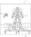
参考图1,示出了增强现实场景1,其中AR技术的用户看到以人、树木、背景中的建筑物和混凝土平台1120为特征的真实世界的公园状设置1100。除了这些物品之外,AR技术的用户还感知到他/她“看到”“虚拟内容”,例如站在真实世界平台1120上的机器人雕像1110,以及看起来是大黄蜂的化身的飞过的卡通式化身角色1130,即使这些元素1130、1110在真实世界中不存在。由于人类的视觉感知系统是复杂的,因此产生促进除其他虚拟或真实世界图像元素之外的虚拟图像元素的舒适的、感觉自然的、丰富的呈现的AR技术是具有挑战性的。Referring to FIG. 1 , an augmented
本文公开的系统和方法解决了与AR和VR技术相关的各种挑战。The systems and methods disclosed herein address various challenges associated with AR and VR technologies.
发明内容Contents of the invention
在一方面,一种衍射光栅包括胆甾型液晶(CLC)层,所述胆甾型液晶层包括多个手性结构,其中每个手性结构包括在层深度方向上延伸至少一个螺距并在第一旋转方向上连续旋转的多个液晶分子。所述螺距是所述层深度方向上的长度,其对应于所述手性结构的液晶分子在所述第一旋转方向上的一个完整旋转的净旋转角。所述手性结构的液晶分子的布置在与所述层深度方向垂直的横向方向上周期性地变化。In one aspect, a diffraction grating comprises a cholesteric liquid crystal (CLC) layer comprising a plurality of chiral structures, wherein each chiral structure comprises at least one pitch extending in the layer depth direction and at A plurality of liquid crystal molecules continuously rotating in the first rotation direction. The pitch is the length in the depth direction of the layer, which corresponds to the net rotation angle of one complete rotation of the liquid crystal molecules of the chiral structure in the first rotation direction. The arrangement of the liquid crystal molecules of the chiral structure changes periodically in a lateral direction perpendicular to the layer depth direction.
在另一方面,一种头戴式显示设备(HMD)被配置为将光投射到用户的眼睛以显示增强现实图像内容。所述HMD包括头戴式显示设备,所述头戴式显示设备包括框架,所述框架被配置为支撑在所述用户的头部上。所述HMD包括显示器,所述显示器被设置在所述框架上,其中所述显示器的至少一部分包括一个或多个波导。所述一个或多个波导是透明的并且在所述用户穿戴着所述头戴式显示设备时设置在用户眼睛前方的位置,使得所述透明部分将来自用户前方环境的一部分的光透射到所述用户眼睛,以提供所述用户前方环境的所述一部分的视图。所述显示器进一步包括一个或多个光源和至少一个衍射光栅,所述衍射光栅被配置为将来自所述光源的光耦入到所述一个或多个波导内或者将光耦出所述一个或多个波导,其中所述至少一个衍射光栅包括根据本说明书的其它地方描述的方面的衍射光栅。In another aspect, a head mounted display device (HMD) is configured to project light to a user's eyes to display augmented reality image content. The HMD includes a head-mounted display device including a frame configured to be supported on the user's head. The HMD includes a display disposed on the frame, wherein at least a portion of the display includes one or more waveguides. The one or more waveguides are transparent and positioned in front of the user's eyes when the user is wearing the head mounted display device such that the transparent portion transmits light from a portion of the environment in front of the user to the user. the user's eyes to provide a view of the portion of the environment in front of the user. The display further includes one or more light sources and at least one diffraction grating configured to couple light from the light sources into the one or more waveguides or out of the one or more waveguides. A plurality of waveguides, wherein the at least one diffraction grating comprises a diffraction grating according to aspects described elsewhere in this specification.
在另一方面,一种波导装置包括一个或多个胆甾型液晶(CLC)层,每个CLC层包括多个手性结构,其中每个手性结构包括在层深度方向上延伸并在第一旋转方向上连续旋转的多个液晶分子,其中所述手性结构的液晶分子的布置在与所述层深度方向垂直的横向方向上周期性地变化,使得所述一个或多个CLC层被配置为布拉格反射(Bragg-reflect)入射光。一个或多个波导形成在所述一个或多个CLC层上方并且被配置为光学耦合布拉格反射光,使得所述布拉格反射光经由全内反射(TIR)在与所述层深度方向垂直的横向方向上传播。所述一个或多个CLC层和所述一个或多个波导被配置为处于相同的光路中。In another aspect, a waveguide device includes one or more cholesteric liquid crystal (CLC) layers, each CLC layer includes a plurality of chiral structures, wherein each chiral structure includes A plurality of liquid crystal molecules continuously rotating in a rotation direction, wherein the arrangement of the liquid crystal molecules of the chiral structure is periodically changed in a lateral direction perpendicular to the layer depth direction, so that the one or more CLC layers are Configured to Bragg-reflect incident light. One or more waveguides are formed above the one or more CLC layers and are configured to optically couple Bragg reflected light such that the Bragg reflected light travels in a lateral direction perpendicular to the layer depth direction via total internal reflection (TIR). on spread. The one or more CLC layers and the one or more waveguides are configured to be in the same optical path.
在另一方面,一种波长选择性胆甾型液晶反射器(CLCR)包括一个或多个胆甾型液晶(CLC)层,每个CLC层包括多个手性结构,其中每个手性结构包括在层深度方向上延伸并在第一旋转方向上连续旋转的多个液晶分子。所述手性结构的液晶分子的布置在与所述层深度方向垂直的横向方向上周期性地变化,使得所述一个或多个CLC层被配置为基本上布拉格反射具有第一波长的第一入射光,同时基本上透射具有第二波长的第二入射光。In another aspect, a wavelength selective cholesteric liquid crystal reflector (CLCR) comprises one or more cholesteric liquid crystal (CLC) layers, each CLC layer comprising a plurality of chiral structures, wherein each chiral structure A plurality of liquid crystal molecules extending in a layer depth direction and continuously rotating in a first rotation direction are included. The arrangement of the liquid crystal molecules of the chiral structure varies periodically in a lateral direction perpendicular to the layer depth direction such that the one or more CLC layers are configured to substantially Bragg reflect a first light having a first wavelength. incident light while substantially transmitting a second incident light having a second wavelength.
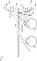
在另一方面,被配置为穿戴在用户头部上的头戴式显示器(HMD)包括框架,所述框架包括一对耳柄(ear stem);一对光学元件,其由所述框架支撑,使得所述一对光学元件中的每一者能够设置在所述用户的眼睛前方;前向成像器,其被安装到所述一对耳柄中的一者;以及胆甾型液晶(CLC)离轴反射镜(mirror),其包括一个或多个胆甾型液晶(CLC)层,每个CLC层包括多个手性结构。每个手性结构包括在层深度方向上延伸并在第一旋转方向上连续旋转的多个液晶分子,其中所述手性结构的液晶分子的布置在与所述层深度方向垂直的横向方向上周期性地变化,使得所述一个或多个CLC层被配置为布拉格反射入射光。所述胆甾型液晶(CLC)离轴反射镜被设置在所述一对光学元件中的一者之中或之上,并且被配置为朝着所述前向成像器反射红外光,所述前向成像器被配置为接收由所述反射元件反射的红外光。In another aspect, a head-mounted display (HMD) configured to be worn on a user's head includes a frame including a pair of ear stems; a pair of optical elements supported by the frame, enabling each of the pair of optical elements to be positioned in front of the user's eyes; a forward-facing imager mounted to one of the pair of ear stems; and a cholesteric liquid crystal (CLC) An off-axis mirror comprising one or more cholesteric liquid crystal (CLC) layers, each CLC layer comprising a plurality of chiral structures. Each chiral structure includes a plurality of liquid crystal molecules extending in a layer depth direction and continuously rotating in a first rotation direction, wherein the liquid crystal molecules of the chiral structure are arranged in a lateral direction perpendicular to the layer depth direction Vary periodically such that the one or more CLC layers are configured to Bragg reflect incident light. the cholesteric liquid crystal (CLC) off-axis mirror is disposed in or on one of the pair of optical elements and is configured to reflect infrared light toward the forward imager, the A forward-facing imager is configured to receive infrared light reflected by the reflective element.
在另一方面,一种波导装置包括一个或多个胆甾型液晶(CLC)层,每个CLC层包括多个手性结构,其中每个手性结构包括在层深度方向上延伸并在第一旋转方向上连续旋转的多个液晶分子,其中所述手性结构的液晶分子的布置在与所述层深度方向垂直的横向方向上周期性地变化,使得所述一个或多个CLC层被配置为布拉格反射入射光。所述波导装置另外包括一个或多个波导,这些波导形成在所述一个或多个CLC层上方并且被配置为光学耦合来自所述一个或多个CLC层的布拉格反射光,使得所述布拉格反射光经由全内反射(TIR)在与所述层深度方向垂直的横向方向上传播。所述波导装置被配置为具有视场(FOV),在该视场内,衍射效率大于25%,该视场超过20°。In another aspect, a waveguide device includes one or more cholesteric liquid crystal (CLC) layers, each CLC layer includes a plurality of chiral structures, wherein each chiral structure includes A plurality of liquid crystal molecules continuously rotating in a rotation direction, wherein the arrangement of the liquid crystal molecules of the chiral structure is periodically changed in a lateral direction perpendicular to the layer depth direction, so that the one or more CLC layers are Configured to Bragg reflect incident light. The waveguide arrangement additionally includes one or more waveguides formed over the one or more CLC layers and configured to optically couple Bragg reflected light from the one or more CLC layers such that the Bragg reflected light Light propagates via total internal reflection (TIR) in a lateral direction perpendicular to the layer depth direction. The waveguide is configured to have a field of view (FOV) within which the diffraction efficiency is greater than 25%, and the field of view exceeds 20°.
在又一方面,一种显示设备包括波导和形成在该波导上的耦入(incoupling)光学元件。耦入光学元件被配置为将入射在其上的光耦入到所述波导的第一侧中,其中耦入光学元件和所述波导被配置为使得被耦入到所述波导中的光经由全内反射(TIR)在所述波导中沿着所述波导的平面内方向传播。所述显示设备另外包括耦出(outcoupling)光学元件,所述耦出光学元件形成在所述波导上并且被配置为将入射在其上的光从所述波导耦出。所述光耦出元件包括胆甾型液晶(CLC)层,该CLC层包括多个手性结构,其中每个手性结构包括在所述CLC层的层深度方向上延伸并在第一旋转方向上连续旋转的多个液晶分子,其中所述手性结构的液晶分子的布置在与所述层深度方向垂直的横向方向上周期性地变化,使得所述一个或多个CLC层被配置为将入射在其上的光从所述波导布拉格反射到所述第一侧。In yet another aspect, a display device includes a waveguide and an incoupling optical element formed on the waveguide. The incoupling optical element is configured to couple light incident thereon into the first side of the waveguide, wherein the incoupling optical element and the waveguide are configured such that the light coupled into the waveguide passes through Total internal reflection (TIR) propagates in the waveguide along an in-plane direction of the waveguide. The display device additionally includes an outcoupling optical element formed on the waveguide and configured to couple light incident thereon out of the waveguide. The light outcoupling element comprises a cholesteric liquid crystal (CLC) layer comprising a plurality of chiral structures, wherein each chiral structure comprises a plurality of liquid crystal molecules continuously rotating on the surface, wherein the arrangement of the liquid crystal molecules of the chiral structure is periodically changed in a lateral direction perpendicular to the layer depth direction, so that the one or more CLC layers are configured to Light incident thereon is reflected from the waveguide Bragg to the first side.
本说明书中描述的主题的一个或多个实施方式的细节在附图和下面的描述中阐述。通过描述、附图和权利要求,其它特征、方面和优点将变得显而易见。本发明内容或下面的具体实施方式都并非旨在限定或限制本发明主题的范围。The details of one or more implementations of the subject matter described in this specification are set forth in the accompanying drawings and the description below. Other features, aspects, and advantages will be apparent from the description, drawings, and claims. Neither this summary nor the following detailed description is intended to define or limit the scope of the inventive subject matter.
附图说明Description of drawings
图1示出了用户通过AR设备观看的增强现实(AR)视图。FIG. 1 shows an Augmented Reality (AR) view viewed by a user through an AR device.
图2示出了可穿戴显示系统的示例。Figure 2 shows an example of a wearable display system.
图3示出了用于为用户模拟三维图像的传统显示系统。Fig. 3 shows a conventional display system for simulating a three-dimensional image for a user.
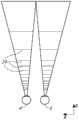
图4示出了使用多个深度平面模拟三维图像的方法的各方面。4 illustrates aspects of a method of simulating a three-dimensional image using multiple depth planes.
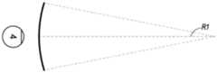
图5A至5C示出了曲率半径与焦半径之间的关系。5A to 5C show the relationship between the radius of curvature and the radius of focus.
图6示出了用于将图像信息输出给用户的波导堆叠的示例。Figure 6 shows an example of a waveguide stack for outputting image information to a user.
图7示出了由波导输出的出射光束的示例。Fig. 7 shows an example of an outgoing beam output by a waveguide.
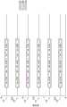
图8示出了堆叠波导组件的示例,其中每个深度平面包括使用多种不同分量颜色形成的图像。Figure 8 shows an example of a stacked waveguide assembly where each depth plane includes an image formed using a plurality of different component colors.
图9A示出了一组堆叠波导的示例的横截面侧视图,每个堆叠波导包括耦入光学元件。9A shows a cross-sectional side view of an example of a set of stacked waveguides, each stacked waveguide including an in-coupling optical element.
图9B示出了图9A的多个堆叠波导的示例的透视图。9B shows a perspective view of an example of the multiple stacked waveguides of FIG. 9A.
图9C示出了图9A和9B的多个堆叠波导的示例的俯视平面图。Figure 9C shows a top plan view of an example of the multiple stacked waveguides of Figures 9A and 9B.
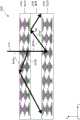
图10示出了具有多个均匀(uniform)手性结构的胆甾型液晶衍射光栅(CLCG)的示例的横截面侧视图。Figure 10 shows a cross-sectional side view of an example of a cholesteric liquid crystal diffraction grating (CLCG) with multiple uniform chiral structures.
图11示出了在横向方向上具有不同地布置的手性结构的CLCG的示例的横截面侧视图。Figure 11 shows a cross-sectional side view of an example of a CLCG with differently arranged chiral structures in the lateral direction.
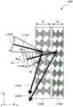
图12示出了被配置为以离轴入射角进行布拉格反射的CLC层的示例的横截面侧视图。12 shows a cross-sectional side view of an example of a CLC layer configured for Bragg reflection at off-axis incidence angles.
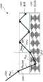
图13A示出了具有第一螺距并且被配置为以第一离轴入射角进行布拉格反射的CLC层的示例的横截面侧视图。13A shows a cross-sectional side view of an example of a CLC layer having a first pitch and configured for Bragg reflection at a first off-axis angle of incidence.
图13B示出了具有第二螺距并且被配置为以第二离轴入射角进行布拉格反射的CLC层的示例的横截面侧视图。13B shows a cross-sectional side view of an example of a CLC layer having a second pitch and configured for Bragg reflection at a second off-axis angle of incidence.
图13C示出了包括图13A和13B的CLC层的CLCG的示例的横截面侧视图,这些CLC层在堆叠配置中具有用于以多个离轴入射角以及高衍射带宽进行布拉格反射的不同螺距。Figure 13C shows a cross-sectional side view of an example of a CLCG comprising the CLC layers of Figures 13A and 13B in a stacked configuration with different pitches for Bragg reflection at multiple off-axis angles of incidence and high diffraction bandwidth .
图14示出了包括具有垂直区域的CLC层的CLCG的示例的横截面侧视图,这些垂直区域具有用于以多个离轴入射角以及高衍射带宽进行布拉格反射的沿深度方向的不同螺距。14 shows a cross-sectional side view of an example of a CLCG comprising a CLC layer with vertical regions with different pitches in depth for Bragg reflection at multiple off-axis angles of incidence and high diffraction bandwidth.
图15示出了包括具有横向区域的CLC层的CLCG的示例的横截面侧视图,这些横向区域具有用于进行在空间上变化的布拉格反射的沿横向方向的螺距。Figure 15 shows a cross-sectional side view of an example of a CLCG comprising a CLC layer with lateral regions having a pitch in the lateral direction for spatially varying Bragg reflection.
图16示出了光学波导装置的示例,该光学波导装置包括被耦合到CLCG并且被配置为经由全内反射(TIR)传播光的波导。Figure 16 shows an example of an optical waveguide arrangement comprising a waveguide coupled to a CLCG and configured to propagate light via total internal reflection (TIR).
图17A示出了光学波导装置的示例,该光学波导装置包括被耦合到CLCG并且被配置为经由全内反射(TIR)选择性地传播具有一波长的光的波导。17A shows an example of an optical waveguide device comprising a waveguide coupled to a CLCG and configured to selectively propagate light having a wavelength via total internal reflection (TIR).
图17B示出了在同一光路中的多个光学波导装置的示例,每个光学波导装置包括被耦合到CLCG并且被配置为经由全内反射(TIR)选择性地传播具有一波长的光的波导。17B shows an example of multiple optical waveguide devices in the same optical path, each optical waveguide device comprising a waveguide coupled to a CLCG and configured to selectively propagate light having a wavelength via total internal reflection (TIR) .
图17C示出了在同一光路中的多个光学波导装置的示例,每个光学波导装置包括被耦合到CLCG并且被配置为经由全内反射(TIR)选择性地传播具有一波长的光的波导。17C shows an example of multiple optical waveguide devices in the same optical path, each optical waveguide device comprising a waveguide coupled to a CLCG and configured to selectively propagate light having a wavelength via total internal reflection (TIR) .
图18示出了光学波导装置的示例,该光学波导装置包括被耦合到多个CLCG并且被配置为经由全内反射(TIR)选择性地传播具有多个波长的光的公共波导。18 shows an example of an optical waveguide arrangement comprising a common waveguide coupled to multiple CLCGs and configured to selectively propagate light having multiple wavelengths via total internal reflection (TIR).
图19示出了光学波导装置的示例,该光学波导装置包括被耦合到CLCG并且被配置为经由全内反射(TIR)传播光的波导。FIG. 19 shows an example of an optical waveguide device comprising a waveguide coupled to a CLCG and configured to propagate light via total internal reflection (TIR).
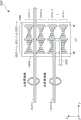
图20示出了光学波导装置的示例,该光学波导装置包括被耦合到CLCG的波导和偏振转换反射器,其中CLCG被配置为接收入射光,波导被配置为经由全内反射(TIR)传播从CLCG布拉格反射的光。20 shows an example of an optical waveguide device comprising a waveguide and a polarization converting reflector coupled to a CLCG, wherein the CLCG is configured to receive incident light and the waveguide is configured to propagate from Light reflected by CLCG Prague.
图21A示出了图20的光学波导装置,其中CLCG被配置为接收线性偏振或非偏振的入射光,并且其中波导被配置为经由全内反射(TIR)传播从CLCG布拉格反射的光和由反射器反射的光。21A shows the optical waveguide device of FIG. 20, wherein the CLCG is configured to receive linearly polarized or unpolarized incident light, and wherein the waveguide is configured to propagate light reflected from the CLCG Bragg and reflected by the reflected light via total internal reflection (TIR). reflector light.
图21B示出了图20的光学波导装置,其中CLCG被配置为接收被偏振成正交的椭圆或圆偏振光束的入射光,并且其中波导被配置为经由全内反射(TIR)传播从CLCG布拉格反射的光和由反射器反射的光。21B shows the optical waveguide device of FIG. 20, wherein the CLCG is configured to receive incident light polarized into orthogonal elliptically or circularly polarized beams, and wherein the waveguide is configured to propagate from the CLCG Bragg via total internal reflection (TIR). The reflected light and the light reflected by the reflector.
图22A示出了入射光束线性偏振或非偏振的状况下的光学波导装置的示例,该光学波导装置包括多个被耦合到公共波导的CLC层,这些CLC层包括第一CLC层和第二CLC层,第一CLC层包括具有第一旋转方向的手性结构,第二CLC层包括具有与第一旋转方向相反的第二旋转方向的手性结构。FIG. 22A shows an example of an optical waveguide device comprising a plurality of CLC layers coupled to a common waveguide, the CLC layers comprising a first CLC layer and a second CLC layer, in the case of a linearly polarized or unpolarized incident light beam. layers, the first CLC layer includes a chiral structure having a first rotation direction, and the second CLC layer includes a chiral structure having a second rotation direction opposite to the first rotation direction.
图22B示出了入射光被偏振成正交的椭圆或圆偏振光束的状况下的图22A的光学波导装置。Fig. 22B shows the optical waveguide device of Fig. 22A in the case where the incident light is polarized into orthogonal elliptically or circularly polarized beams.
图22C示出了入射光束线性偏振或非偏振的状况下的光学波导装置的示例,该光学波导装置包括多个被耦合到插在两个CLC层之间的公共波导的CLC层,这些CLC层包括第一CLC层和第二CLC层,第一CLC层包括具有第一旋转方向的手性结构,第二CLC层包括具有与第一旋转方向相反的第二旋转方向的手性结构。22C shows an example of an optical waveguide device comprising a plurality of CLC layers coupled to a common waveguide interposed between two CLC layers in the case of linearly polarized or unpolarized incident light beams, the CLC layers It includes a first CLC layer and a second CLC layer, the first CLC layer includes a chiral structure with a first rotation direction, and the second CLC layer includes a chiral structure with a second rotation direction opposite to the first rotation direction.
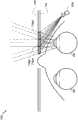
图23示出了包括前向相机的成像系统的示例,该前向相机被配置为使用胆甾型液晶(CLC)离轴反射镜对穿戴者的眼睛进行成像。23 illustrates an example of an imaging system including a forward-facing camera configured to image a wearer's eye using a cholesteric liquid crystal (CLC) off-axis mirror.
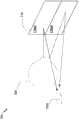
图24A至24F示出了包括前向相机的成像系统的示例,该前向相机被配置为使用CLC离轴反射镜对穿戴者的眼睛进行成像。24A to 24F illustrate an example of an imaging system including a forward-facing camera configured to image a wearer's eye using a CLC off-axis mirror.
图24G和24H示出了包括前向相机的成像系统的示例,该前向相机被配置为使用衍射光学元件对穿戴者的眼睛进行成像,该衍射光学元件包括多个包含一个或多个CLC离轴反射镜的区段(segment),其中每个区段可具有不同的光学特性。24G and 24H illustrate examples of imaging systems including a forward-facing camera configured to image a wearer's eye using a diffractive optical element comprising multiple Segments of an axicon mirror, where each segment may have different optical properties.
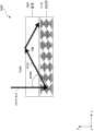
图25示出了针对宽视场范围而优化的示例光学波导装置,该光学波导装置包括被耦合到CLCG且被配置为经由全内反射(TIR)传播光的波导。25 illustrates an example optical waveguide optimized for a wide field of view comprising a waveguide coupled to a CLCG and configured to propagate light via total internal reflection (TIR).
图26示出了被配置作为耦出光学元件的示例光学波导装置,该光学波导装置包括被耦合到CLCG并且被配置为经由全内反射(TIR)传播光的波导。26 illustrates an example optical waveguide device configured as an outcoupling optical element, the optical waveguide device comprising a waveguide coupled to a CLCG and configured to propagate light via total internal reflection (TIR).
在整个附图中,可以重复使用参考标号来指示所提及的元件之间的对应关系。提供附图是为了说明本文描述的示例实施例,并且不旨在限制本公开的范围。Throughout the drawings, reference numerals may be re-used to indicate correspondence between mentioned elements. The drawings are provided to illustrate example embodiments described herein and are not intended to limit the scope of the present disclosure.
具体实施方式Detailed ways
AR系统可以向用户或观看者显示虚拟内容,同时仍然允许用户看到其周围的世界。优选地,该内容在头戴式显示器(例如作为眼镜的一部分)上显示,头戴式显示器将图像信息投射到用户的眼睛。另外,显示器还可以将来自周围环境的光透射到用户的眼睛,以允许观看该周围环境。如本文所使用的,应当理解,“头戴式”显示器是可以安装在观看者头部上的显示器。AR systems can display virtual content to a user or viewer, while still allowing the user to see the world around them. Preferably, the content is displayed on a head mounted display (eg as part of glasses) which projects image information to the user's eyes. In addition, the display may also transmit light from the surrounding environment to the user's eyes to allow viewing of the surrounding environment. As used herein, it should be understood that a "head-mounted" display is a display that may be mounted on a viewer's head.
图2示出了可穿戴显示系统80的示例。显示系统80包括显示器62,以及支持该显示器62的功能的各种机械和电子模块和系统。显示器62可以被耦接到框架64,该框架可由显示系统用户或观看者60穿戴,并且被配置为将显示器62定位在用户60的眼睛前方。在一些实施例中,显示器62可以被视为眼镜。在一些实施例中,扬声器66被耦接到框架64并且被定位在用户60的耳道附近(在一些实施例中,另一扬声器(未示出)被定位在用户的另一耳道附近以提供立体/可塑形的声音控制)。在一些实施例中,显示系统还可以包括一个或多个麦克风67或其它检测声音的设备。在一些实施例中,麦克风被配置为允许用户向系统80提供输入或命令(例如,语音菜单命令的选择、自然语言问题等)和/或可以允许与其它人(例如,与类似显示系统的其他用户)进行音频通信。麦克风还可以被配置为外围传感器以连续收集音频数据(例如,以被动地从用户和/或环境收集)。这种音频数据可以包括用户声音(诸如重呼吸)或环境声音(诸如指示附近事件的巨响)。显示系统还可以包括外围传感器30a,其可以与框架64分离并且被附接到用户60的身体(例如,在用户60的头部、躯干、四肢等上)。如本文进一步描述的,在一些实施例中,外围传感器30a可以被配置为获取表征用户60的生理状态的数据。例如,传感器30a可以是电极。FIG. 2 shows an example of a wearable display system 80 . Display system 80 includes
继续参考图2,显示器62通过通信链路68(例如通过有线引线或无线连接)可操作地耦接到本地数据处理模块70,本地数据处理模块70可以以各种配置被安装,例如固定地附接到框架64,固定地附接到用户所戴的头盔或帽子,嵌入耳机中,或以其它方式可移除地附接到用户60(例如,采取背包式配置,采取腰带耦接式配置)。类似地,传感器30a可通过通信链路30b(例如通过有线引线或无线连接)可操作地耦接到本地处理和数据模块70。本地处理和数据模块70可以包括硬件处理器,以及数字存储器,诸如非易失性存储器(例如,闪速存储器或硬盘驱动器),这两者都可被用于辅助数据的处理、缓存和存储。这些数据包括:a)从传感器(其例如可以可操作地耦接到框架64或以其它方式附接到用户60)捕获的数据,这些传感器例如为图像捕获设备(如相机)、麦克风、惯性测量单元、加速度计、指南针、GPS单元、无线电设备、陀螺仪和/或此处公开的其它传感器;和/或b)使用远程处理模块72和/或远程数据储存库74获取和/或处理的数据(包括与虚拟内容相关的数据),这些数据可能在被这样的处理或检索之后被传送到显示器62。本地处理和数据模块70可以通过通信链路76、78(诸如经由有线或无线通信链路)可操作地耦接到远程处理模块72和远程数据储存库74,使得这些远程模块72、74可操作地彼此耦接,并且作为资源可用于本地处理和数据模块70。在一些实施例中,本地处理和数据模块70可以包括图像捕获设备、麦克风、惯性测量单元、加速度计、指南针、GPS单元、无线电设备和/或陀螺仪中的一者或多者。在一些其它实施例中,这些传感器中的一者或多者可以附接到框架64,或者可以是通过有线或无线通信路径与本地处理和数据模块70通信的独立结构。With continued reference to FIG. 2 , the
继续参考图2,在一些实施例中,远程处理模块72可以包括被配置为分析和处理数据和/或图像信息的一个或多个处理器。在一些实施例中,远程数据储存库74可以包括数字数据存储设施,该设施可以通过因特网或“云”资源配置中的其它网络配置获得。在一些实施例中,远程数据储存库74可以包括一个或多个远程服务器,这些服务器向本地处理和数据模块70和/或远程处理模块72提供信息,例如用于生成增强现实内容的信息。在一些实施例中,所有数据都被存储,所有计算都在本地处理和数据模块中被执行,允许从远程模块完全自主地使用。With continued reference to FIG. 2 , in some embodiments,
可以通过向观看者的每只眼睛提供略微不同的图像呈现来实现将图像感知为“三维的”或“3D”。图3示出了用于模拟用户的三维图像的传统显示系统。向用户输出两个不同图像5、7,其中每个图像针对一只眼睛4、6。图像5、7沿着平行于观看者视线的光轴或z轴而与眼睛4、6相隔一距离10。图像5、7是平坦的,眼睛4、6可以通过假设单个调节状态而聚焦在这些图像上。这样的系统依赖于人类视觉系统来组合图像5、7以为组合图像提供深度感和/或缩放。Perceiving an image as "three-dimensional" or "3D" can be achieved by providing a slightly different presentation of the image to each eye of the viewer. FIG. 3 shows a conventional display system for simulating a three-dimensional image of a user. Two different images 5, 7 are output to the user, where each image is for one
然而,应当理解,人类视觉系统更复杂,并且提供逼真的深度感更具挑战性。例如,传统的“3-D”显示系统的许多观看者发现这样的系统不舒服或者根本不能感知到深度感。不受理论的限制,据信对象的观看者可由于聚散和调节的组合而将对象感知为“三维的”。两只眼睛相对于彼此的聚散运动(例如,眼睛的转动使得瞳孔朝向彼此或远离彼此运动以使眼睛的视线会聚以注视在对象上)与眼睛的晶状体和瞳孔的聚焦(或者调节)密切相关。在正常情况下,改变眼睛的晶状体的焦点或调节眼睛,以将焦点从一个对象改变到不同距离处的另一对象将根据被称为“调节-聚散反射”的关系以及瞳孔扩张或收缩而自动导致与同一距离匹配的聚散度变化。同样,在正常条件下,聚散度的变化将触发晶状体形状和瞳孔大小的匹配的调节变化。如本文所指出的,许多立体或“3-D”显示系统使用略微不同的呈现(以及,因此略微不同的图像)向每只眼睛显示场景,使得人类视觉系统感知到三维透视。然而,这样的系统对于许多观看者来说是不舒服的,因为它们除了其余内容之外简单地提供场景的不同呈现,而眼睛在单个调节状态下观看所有图像信息,并且违反“调节-聚散反射”起作用。在调节和聚散之间提供更好匹配的显示系统可以形成更逼真和舒适的三维图像模拟,从而有助于增加穿戴持续时间,进而遵从诊断和治疗协议。However, it should be appreciated that the human visual system is more complex and providing a realistic perception of depth is more challenging. For example, many viewers of conventional "3-D" display systems find such systems uncomfortable or incapable of perceiving a sense of depth at all. Without being bound by theory, it is believed that a viewer of an object may perceive the object as "three-dimensional" due to a combination of vergence and accommodation. The vergent movement of the two eyes relative to each other (for example, the rotation of the eyes so that the pupils move toward or away from each other to bring the eyes' sights together to fixate on an object) is closely related to the focusing (or accommodation) of the eye's lens and pupils . Under normal circumstances, changing the focus of the lens of the eye or accommodating the eye to change the focus from one object to another at a different distance will respond according to a relationship known as the "accommodation-vergence reflex" and pupil dilation or constriction Automatically results in vergence changes that match the same distance. Also, under normal conditions, changes in vergence will trigger matching accommodative changes in lens shape and pupil size. As noted herein, many stereoscopic or "3-D" display systems display a scene to each eye using slightly different presentations (and, therefore, slightly different images) such that the human visual system perceives three-dimensional perspective. However, such systems are uncomfortable for many viewers because they simply provide different presentations of the scene in addition to the rest, while the eye views all image information in a single accommodation state, and violates the "accommodation-vergence reflection" works. A display system that provides a better match between accommodation and vergence can result in a more realistic and comfortable 3D image simulation, helping to increase wear duration and thus adherence to diagnostic and therapeutic protocols.
图4示出了使用多个深度平面模拟三维图像的方法的各方面。参考图4,z轴上距眼睛4、6不同距离处的对象由眼睛4、6调节,以使这些对象焦点对准(in focus)。眼睛(4和6)呈现特定的调节状态,以使沿着z轴的不同距离处的对象进入焦点。因此,可以说特定的调节状态与深度平面14中的特定一个深度平面相关联,该特定深度平面具有相关联的焦距,以使得当眼睛处于针对该深度平面的调节状态时,特定深度平面中的对象或对象的部分焦点对准。在一些实施例中,可以通过为每只眼睛4、6提供图像的不同呈现来模拟三维图像,并且还可以通过提供与深度平面中每一个深度平面对应的图像的不同呈现来模拟三维图像。尽管为了清楚说明而示出为分离的,但应理解,例如,随着沿着z轴的距离增加,眼睛4、6的视野可以重叠。另外,尽管为了便于说明而示出为平坦的,但是应当理解,深度平面的轮廓可以在物理空间中弯曲,使得深度平面中的所有特征在眼睛处于特定调节状态时焦点对准。4 illustrates aspects of a method of simulating a three-dimensional image using multiple depth planes. Referring to Fig. 4, objects at different distances on the z-axis from the
对象与眼睛4或6之间的距离也可以改变来自该眼睛所看到的对象的光的发散量。图5A至5C示出了距离和光线发散之间的关系。对象与眼睛4之间的距离按照递减的次序由距离R1、R2和R3表示。如图5A至5C所示,随着到对象的距离减小,光线变得更加发散。随着距离的增加,光线变得更加准直。换句话说,可以说,由点(对象或对象的一部分)产生的光场具有球面波前曲率,其是该点距用户眼睛的距离的函数。随着对象与眼睛4之间的距离减小,曲率增大。因此,在不同的深度平面处,光线的发散度也不同,发散度随着深度平面与观看者眼睛4之间的距离的减小而增大。尽管为了在图5A至5C和本文中的其它图中清楚地说明而仅示出单只眼睛4,但是应当理解,关于眼睛4的讨论可以应用于观看者的双眼4和6。The distance between the object and the
不受理论的限制,据信人类眼睛通常可以解释有限数量的深度平面以提供深度感知。因此,通过向眼睛提供与这些有限数量的深度平面中的每一个深度平面对应的图像的不同呈现,可以实现感知深度的高度可信的模拟。不同的呈现可以由观看者的眼睛单独聚焦,从而有助于基于使位于不同深度平面上的场景的不同图像特征进入焦点所需的眼睛调节和/或基于观察到在不同深度平面上的不同图像特征的焦点没对准,为用户提供深度线索。Without being bound by theory, it is believed that the human eye can generally interpret a limited number of depth planes to provide depth perception. Thus, by providing the eye with a different presentation of the image corresponding to each of these limited number of depth planes, a highly reliable simulation of perceived depth can be achieved. Different presentations can be individually focused by the viewer's eyes, facilitating eye accommodation based on the need to bring different image features of the scene at different depth planes into focus and/or based on viewing different images at different depth planes Features are out of focus, giving users depth cues.
图6示出了用于将图像信息输出给用户的波导堆叠的示例。显示系统1000包括波导堆叠或堆叠波导组件178,其可用于使用多个波导1182、1184、1186、1188、1190向眼睛/大脑提供三维感知。在一些实施例中,显示系统1000是图2的系统80,图6更详细地示意性地示出了该系统80的一些部分。例如,波导组件1178可以是图2的显示器62的一部分。将理解,在一些实施例中,显示系统1000可以被视为光场显示器。Figure 6 shows an example of a waveguide stack for outputting image information to a user.
继续参考图6,波导组件1178还可以包括位于波导之间的多个特征1198、1196、1194、1192。在一些实施例中,特征1198、1196、1194、1192可以是一个或多个透镜。波导1182、1184、1186、1188、1190和/或多个透镜1198、1196、1194、1192可以被配置为以各种水平的波前曲率或光线发散度向眼睛发送图像信息。每个波导级可以与特定深度平面相关联,并且可以被配置为输出对应于该深度平面的图像信息。图像注入装置1200、1202、1204、1206、1208可以用作波导的光源,并且可用于将图像信息注入到波导1182、1184、1186、1188、1190中,如本文所述,每个波导可以被配置为将入射光分配穿过每个相应的波导以朝着眼睛4输出。光从图像注入装置1200、1202、1204、1206、1208的输出表面1300、1302、1304、1306、1308出射,并且注入到波导1182、1184、1186、1188、1190的相应输入表面1382、1384、1386、1388、1390中。在一些实施例中,输入表面1382、1384、1386、1388、1390中的每一者可以是相应波导的边,或者可以是相应波导的主表面(即,直接面向世界1144或观看者眼睛4的波导表面中的一者)的一部分。在一些实施例中,可以将单个光束(例如准直光束)注入到每个波导中,以便以与特定波导相关联的深度平面对应的特定角度(和发散量)输出朝向眼睛4定向的克隆准直光束的整个视野。在一些实施例中,图像注入装置1200、1202、1204、1206、1208的一者可以与多个波导1182、1184、1186、1188、1190(例如,其中的三个)相关联并将光注入到这些波导中。With continued reference to FIG. 6 , the
在一些实施例中,图像注入装置1200、1202、1204、1206、1208是离散显示器,每个离散显示器分别产生用于注入到对应的波导1182、1184、1186、1188、1190中的图像信息。在一些其它实施例中,图像注入装置1200、1202、1204、1206、1208是单个多路复用显示器的输出端,例如,多路复用显示器可以经由一个或多个光学导管(例如,光纤光缆)将图像信息通过管道传输到图像注入装置1200、1202、1204、1206、1208中的每一者。将理解,由图像注入装置1200、1202、1204、1206、1208提供的图像信息可以包括不同波长或颜色的光(例如,如本文所讨论的不同的分量颜色)。In some embodiments, the
在一些实施例中,注入到波导1182、1184、1186、1188、1190中的光由光投射器系统2000提供,光投射器系统2000包括光模块2040,光模块2040可以包括光发射器,例如发光二极管(LED)。来自光模块2040的光可以经由分束器2050而被引导到光调制器2030(例如,空间光调制器)以及被光调制器2030修改。光调制器2030可以被配置为改变注入到波导1182、1184、1186、1188、1190中的光的感知强度。空间光调制器的示例包括液晶显示器(LCD),其包括硅上液晶(LCOS)显示器。In some embodiments, the light injected into the
在一些实施例中,显示系统1000可以是包括一个或多个扫描光纤的扫描光纤显示器,扫描光纤被配置为以各种图案(例如,光栅扫描、螺旋扫描、利萨如图案等)将光投射到一个或多个波导1182、1184、1186、1188、1190中并最终投射到观看者的眼睛4。在一些实施例中,所示的图像注入装置1200、1202、1204、1206、1208可示意性地表示单个扫描光纤或扫描光纤束,单个扫描光纤或扫描光纤束被配置为将光注入到一个或多个波导1182、1184、1186、1188、1190中。在一些其它实施例中,所示的图像注入装置1200、1202、1204、1206、1208可以示意性地表示多个扫描光纤或多个扫描光纤束,这些扫描光纤或扫描光纤束中的每一者被配置为将光注入到波导1182、1184、1186、1188、1190中关联的一者中。应当理解,一个或多个光纤可以被配置为将光从光模块2040传输到一个或多个波导1182、1184、1186、1188、1190。应当理解,可以在一个或多个扫描光纤与一个或多个波导1182、1184、1186、1188、1190之间提供一个或多个居间光学结构,以例如将从扫描光纤出射的光重定向到一个或多个波导1182、1184、1186、1188、1190中。In some embodiments,
控制器1210控制堆叠波导组件1178中的一者或多者的操作,包括图像注入装置1200、1202、1204、1206、1208、光源2040和光调制器2030的操作。在一些实施例中,控制器1210是本地数据处理模块70的一部分。控制器1210包括编程(例如,非暂时性介质中的指令),该编程根据例如本文公开的各种方案中的任何方案,调节定时和向波导1182、1184、1186、1188、1190的图像信息提供。在一些实施例中,控制器可以是单个集成设备,或者是通过有线或无线通信信道连接的分布式系统。在一些实施例中,控制器1210可以是处理模块70或72(图1)的一部分。
继续参考图6,波导1182、1184、1186、1188、1190可以被配置为通过全内反射(TIR)在每个相应的波导内传播光。波导1182、1184、1186、1188、1190可以各自是平面的或具有另一形状(例如,弯曲的),具有顶部主表面和底部主表面以及在这些顶部主表面和底部主表面之间延伸的边缘。在所示的配置中,波导1182、1184、1186、1188、1190可各自包括耦出(outcoupling)光学元件1282、1284、1286、1288、1290,这些元件被配置为通过重定向光来从波导中提取光,在各自对应的波导内部传播,从波导出射以将图像信息输出到眼睛4。所提取的光也可以被称为耦出光,而耦出光学元件光也可以被称为光提取光学元件。在波导中传播的光照射到光提取光学元件的位置处,所提取的光束由波导输出。如本文进一步讨论的,耦出光学元件1282、1284、1286、1288、1290可以例如是光栅,光栅包括衍射光学特征。虽然为了便于描述和描绘清楚而被示出为设置在波导1182、1184、1186、1188、1190的底部主表面处,但是在一些实施例中,如本文进一步所讨论的,耦出光学元件1282、1284、1286、1288、1290可以被设置在顶部和/或底部主表面处,和/或可以被直接设置在波导1182、1184、1186、1188、1190的体中。在一些实施例中,耦出光学元件1282、1284、1286、1288、1290可以被形成在附接到透明基板的材料层中,以形成波导1182、1184、1186、1188、1190。在一些其它实施例中,波导1182、1184、1186、1188、1190可以是单片材料,且耦出光学元件1282、1284、1286、1288、1290可以被形成在该片材料的表面上和/或内部中。With continued reference to FIG. 6, the
继续参考图6,如本文所讨论的,每个波导1182、1184、1186、1188、1190被配置为输出光以形成对应于特定深度平面的图像。例如,最靠近眼睛的波导1182可以被配置为将注入到这种波导1182中的准直光传送到眼睛4。准直光可以代表光学无限远焦平面。下一个上行波导1184可以被配置为将穿过第一透镜1192(例如,负透镜)的准直光在其可以到达眼睛4之前发送出;这样的第一透镜1192可以被配置为产生微凸的波前曲率,使得眼睛/大脑将来自下一个上行波导1184的光解释为来自第一焦平面,该第一焦平面从光学无限远处更靠近向内朝向眼睛4。类似地,第三上行波导1186使其输出光在到达眼睛4之前通过第一透镜1192和第二透镜1194;第一透镜1192和第二透镜1194的组合光焦度(optical power)可被配置为产生另一增量的波前曲率,以使得眼睛/大脑将来自第三波导1186的光解释为来自第二焦平面,该第二焦平面从光学无穷远比来自下一个上行波导1184的光更靠近向内朝向人。Continuing with reference to FIG. 6 , as discussed herein, each
其它波导层1188、1190和透镜1196、1198被类似地配置,其中堆叠中的最高波导1190通过其与眼睛之间的所有透镜发送其输出,以获得代表与人最接近的焦平面的聚合焦度(aggregate focal power)。为了在观看/解释来自堆叠波导组件1178的另一侧上的世界1144的光时补偿透镜堆叠1198、1196、1194、1192,可以在堆叠的顶部设置补偿透镜层1180以补偿下面的透镜堆叠1198、1196、1194、1192的聚合焦度。这种配置提供与可用的波导/透镜配对一样多的感知焦平面。波导的耦出光学元件和透镜的聚焦方面都可以是静态的(即,不是动态的或电活性的)。在一些替代实施例中,它们中的一者或全部两者可以是使用电活性特征而动态的。The
在一些实施例中,波导1182、1184、1186、1188、1190中的两者或更多者可具有相同的相关深度平面。例如,多个波导1182、1184、1186、1188、1190可以被配置为将图像集输出到相同的深度平面,或者波导1182、1184、1186、1188、1190的多个子集可以被配置为将图像集输出到相同的多个深度平面,每个深度平面一个图像集。这可以提供形成平铺图像以在那些深度平面处提供扩展的视野的优势。In some embodiments, two or more of the
继续参考图6,耦出光学元件1282、1284、1286、1288、1290可以被配置为将光重定向到它们相应的波导之外并且针对与该波导相关联的特定深度平面输出具有适当的发散量或准直量的该光。结果,具有不同相关联深度平面的波导可具有不同的耦出光学元件1282、1284、1286、1288、1290的配置,这些耦出光学元件依赖于相关联的深度平面而输出具有不同发散量的光。在一些实施例中,光提取光学元件1282、1284、1286、1288、1290可以是体或表面特征,其可以被配置为以特定角度输出光。例如,光提取光学元件1282、1284、1286、1288、1290可以是体全息图、表面全息图和/或衍射光栅。在一些实施例中,特征1198、1196、1194、1192可以不是透镜;相反,它们可以简单地是间隔物(例如,包层和/或用于形成气隙的结构)。With continued reference to FIG. 6 , the outcoupling
在一些实施例中,耦出光学元件1282、1284、1286、1288、1290是形成衍射图案的衍射特征,或“衍射光学元件”(在本文中也被称为“DOE”)。优选地,DOE具有足够低的衍射效率(衍射光束强度与入射光束强度的比率),以使得光束的仅一部分光通过DOE的每一个交点而偏转向眼睛4,而其余部分经由全内反射而继续移动通过波导。携带图像信息的光因此被分成多个相关的出射光束,这些出射光束在多个位置处离开波导,并且结果对于在波导内反弹的该特定准直光束是朝向眼睛4的相当均匀图案的出射发射。In some embodiments, the outcoupling
在一些实施例中,一个或多个DOE可以在它们活跃地衍射的“开”状态与它们不显著衍射的“关”状态之间可切换。例如,可切换的DOE可以包括聚合物分散液晶层,其中微滴在主体介质中包含衍射图案,并且微滴的折射率可以被切换为基本上匹配主体材料的折射率(在这种情况下,图案不会明显地衍射入射光),或者微滴可以被切换为与主体介质的折射率不匹配的折射率(在这种情况下,该图案活跃地衍射入射光)。In some embodiments, one or more DOEs may be switchable between their actively diffracting "on" state and their insignificantly diffracting "off" state. For example, a switchable DOE can include a polymer-dispersed liquid crystal layer in which the droplets contain a diffractive pattern in the host medium, and the refractive index of the droplets can be switched to substantially match that of the host material (in this case, pattern does not significantly diffract incident light), or the droplet can be switched to a refractive index that does not match that of the host medium (in which case the pattern actively diffracts incident light).
在一些实施例中,可提供相机组件500(例如,数字相机,包括可见光和红外光相机)以捕获眼睛4和/或眼睛4周围的组织的图像,从而例如检测用户输入和/或监测用户的生理状态。如本文所使用的,相机可以是任何图像捕获设备。在一些实施例中,相机组件500可以包括图像捕获设备和光源,以将光(例如,红外光)投射到眼睛,然后光可以被眼睛反射并被图像捕获设备检测到。在一些实施例中,相机组件500可以被附接到框架64(图2)并且可以与处理模块70和/或72电通信,处理模块70和/或72可以处理来自相机组件500的图像信息,以做出关于例如用户的生理状态的各种确定,如本文所述的。应当理解,关于用户的生理状态的信息可被用于确定用户的行为或情绪状态。此类信息的示例包括用户的动作和/或用户的面部表情。然后可以利用所收集的环境和/或虚拟内容数据对用户的行为或情绪状态进行三角测量,以便确定行为或情绪状态、生理状态和环境或虚拟内容数据之间的关系。在一些实施例中,可以针对每只眼睛使用一个相机组件500以分别监测每只眼睛。In some embodiments, a camera assembly 500 (e.g., a digital camera, including visible and infrared cameras) may be provided to capture images of the
现在参考图7,其中示出了由波导输出的出射光束的示例。示出了一个波导,但是应当理解,波导组件1178(图6)中的其它波导可以类似地起作用,其中波导组件1178包括多个波导。光400在波导1182的输入表面1382处被注入到波导1182中,并通过TIR在波导1182内传播。在光400照射在DOE 282上的点处,一部分光作为出射光束402离开波导。出射光束402被示例为基本上平行,但是如本文所讨论的,依赖于与波导1182相关联的深度平面,出射光束402也可以以一角度(例如,形成发散的出射光束)被重定向以传播到眼睛4。应该理解,基本上平行的出射光束可以指示具有耦出光学元件的波导,所述耦出光学元件将光耦出以形成看起来被设置在距眼睛4较大距离(例如,光学无穷远)处的深度平面上的图像。其它波导或者其它耦出光学元件组可以输出更加发散的出射光束图案,这将需要眼睛4调节到更近距离以将其聚焦在视网膜上并且将被大脑解释为来自比光学无穷远更接近眼睛4的距离的光。Referring now to FIG. 7, there is shown an example of an exit beam output by a waveguide. One waveguide is shown, but it should be understood that other waveguides in waveguide assembly 1178 (FIG. 6), which includes multiple waveguides, may function similarly.
在一些实施例中,可以通过在分量颜色(例如,三种或更多种分量颜色)中的每一者中叠加图像来在每个深度平面处形成全色图像。图8示出了堆叠波导组件的示例,其中,每个深度平面包括使用多种不同分量颜色形成的图像。所示的实施例示出了深度平面14a-14f,但也可以预期更多或更少的深度。每个深度平面可以具有与其相关联的三个分量颜色图像:第一颜色G的第一图像;第二颜色R的第二图像;以及第三颜色B的第三图像。对于字母G,R和B之后的屈光度(dpt),在图中通过不同的数字表示不同的深度平面。仅作为示例,这些字母中的每一者后面的数字表示屈光度(1/m),或该深度平面距观看者的距离的倒数,并且图中的每个框表示单独的分量颜色图像。在一些实施例中,为了考虑眼睛对不同波长的光的聚焦的差异,不同分量颜色的深度平面的精确放置可以变化。例如,给定深度平面的不同分量颜色图像可以被放置在与距用户的不同距离相对应的深度平面上。这样的布置可以增加视敏度和用户舒适度,和/或可以减少色差。In some embodiments, a full-color image may be formed at each depth plane by superimposing images in each of component colors (eg, three or more component colors). Figure 8 shows an example of a stacked waveguide assembly where each depth plane includes an image formed using a plurality of different component colors. The illustrated embodiment shows
在一些实施例中,每种分量颜色的光可以由单个专用波导输出,因此,每个深度平面可以具有与其相关联的多个波导。在这样的实施例中,图中包括字母G、R或B的每个框可以被理解为表示单独的波导,并且每个深度平面可以提供三个波导,其中,每个深度平面提供三个分量颜色图像。尽管为了便于描述,在此图中与每个深度平面相关联的波导被示出为邻近彼此,但应当理解,在物理设备中,波导可以全部被布置为每层级一个波导的堆叠形式。在一些其他实施例中,多个分量颜色可以由相同的波导输出,使得例如每个深度平面可以仅提供单个波导。In some embodiments, each component color of light may be output by a single dedicated waveguide, thus, each depth plane may have multiple waveguides associated therewith. In such an embodiment, each box in the figure including the letter G, R, or B may be understood to represent a separate waveguide, and each depth plane may provide three waveguides, wherein each depth plane provides three component color image. Although the waveguides associated with each depth plane are shown adjacent to each other in this figure for ease of description, it should be understood that in a physical device the waveguides may all be arranged in a stack of one waveguide per level. In some other embodiments, multiple component colors may be output by the same waveguide, so that for example only a single waveguide may be provided per depth plane.
继续参考图8,在一些实施例中,G是绿色,R是红色,B是蓝色。在一些其他实施例中,除了红色、绿色或蓝色之外,可以使用与其他波长的光(包括品红色和青色)相关联的其他颜色,或者这些其他颜色可以替代红色,绿色或蓝色中的一种或多种。在一些实施例中,特征198、196、194和192可以是有源或无源光学滤波器,其被配置为阻挡来自周围环境的光或选择性地允许来自周围环境的光到达观看者的眼睛。Continuing to refer to FIG. 8 , in some embodiments, G is green, R is red, and B is blue. In some other embodiments, other colors associated with other wavelengths of light (including magenta and cyan) may be used in addition to, or instead of, red, green, or blue. one or more of . In some embodiments, features 198, 196, 194, and 192 may be active or passive optical filters configured to block light from the surrounding environment or selectively allow light from the surrounding environment to reach the viewer's eyes .
应当理解,本公开通篇对给定颜色的光的提及将被理解为包括在被观看者感知为具有该给定颜色的光的波长范围内的一个或多个波长的光。例如,红光可以包括在约620-780nm范围内的一个或多个波长的光,绿光可以包括在约492-577nm范围内的一个或多个波长的光,并且蓝光可以包括在约435-493nm范围内的一个或多个波长的光。It should be understood that references throughout this disclosure to light of a given color will be understood to include light of one or more wavelengths within the wavelength range perceived by a viewer as light of that given color. For example, red light may include light of one or more wavelengths in the range of about 620-780 nm, green light may include light of one or more wavelengths in the range of about 492-577 nm, and blue light may include light of one or more wavelengths in the range of about 435-577 nm. One or more wavelengths of light in the 493nm range.
在一些实施例中,光源2040(图6)可以被配置为发射观看者的视觉感知范围之外的一个或多个波长的光,例如红外和/或紫外波长的光。此外,显示器1000的波导的耦入、耦出和其它光重定向结构可以被配置为引导此光并使此光从显示器出射朝向用户的眼睛4,例如用于成像和/或用户激励应用。In some embodiments, light source 2040 (FIG. 6) may be configured to emit light at one or more wavelengths outside the range of visual perception of a viewer, such as infrared and/or ultraviolet wavelengths of light. Furthermore, the incoupling, outcoupling, and other light redirecting structures of the waveguides of the
现在参考图9A,在一些实施例中,可能需要将照射在波导上的光重定向以将该光耦入到波导中。可以使用耦入光学元件将光重定向并且耦入到其对应的波导中。图9A示出了多个堆叠波导或堆叠波导组1200的示例的横截面侧视图,每个波导包括耦入光学元件。波导可以被各自配置为输出一个或多个不同波长的光,或一个或多个不同波长范围的光。应当理解,堆叠1200可以对应于堆叠1178(图6),并且除了来自图像注入装置1200、1202、1204、1206、1208中的一者或多者的光从需要光被重定向以耦入的位置被注入到波导中之外,堆叠1200的所示波导可以对应于多个波导1182、1184、1186、1188、1190的一部分。Referring now to FIG. 9A, in some embodiments, it may be desirable to redirect light impinging on a waveguide to couple the light into the waveguide. Light may be redirected and coupled into its corresponding waveguide using incoupling optics. Figure 9A shows a cross-sectional side view of an example of a plurality of stacked waveguides or set of
所示的堆叠波导组1200包括波导1210、1220和1230。每个波导包括关联的耦入光学元件(其也可以被称为波导上的光输入区域),其中例如耦入光学元件1212被设置在波导1210的主表面(例如,顶部主表面)上,耦入光学元件1224被设置在波导1220的主表面(例如,顶部主表面)上,耦入光学元件1232被设置在波导1230的主表面(例如,顶部主表面)上。在一些实施例中,耦入光学元件1212、1222、1232中的一者或多者可以被设置在相应波导1210、1220、1230的底部主表面上(特别是在一个或多个耦入光学元件是反射性的偏转光学元件的情况下)。如图所示,耦入光学元件1212、1222、1232可以被设置在它们相应的波导1210、1220、1230(或下一下行波导的顶部)的顶部主表面上,特别是在那些耦入光学元件是透射性的偏转光学元件的情况下。在一些实施例中,耦入光学元件1212、1222、1232可以被设置在相应的波导1210、1220、1230的体中。在一些实施例中,如本文所讨论的,耦入光学元件1212、1222、1232是波长选择性的,使得它们选择性地重定向一个或多个波长的光,同时透射其他波长的光。尽管在它们相应的波导1210、1220、1230的一侧或角上示出,但是应当理解,在一些实施例中,耦入光学元件1212、1222、1232可以被设置在它们相应的波导1210、1220、1230的其它区域中。The illustrated set of
如图所示,耦入光学元件1212、1222、1232可以彼此横向偏移。在一些实施例中,每个耦入光学元件可以被偏移,使得耦入光学元件接收光,而该光无需传输通过另一耦入光学元件。例如,如图6所示,每个耦入光学元件1212、1222、1232可以被配置为从不同的图像注入装置1200、1202、1204、1206和1208接收光,并且可以与其它耦入光学元件1212、1222、1232分开(例如,横向间隔开),使得该耦入光学元件基本上不接收来自耦入光学元件1212、1222、1232中的其它耦入光学元件的光。As shown, the incoupling
每个波导还包括关联的光分布元件,其中,例如,光分布元件1214被设置在波导1210的主表面(例如,顶部主表面)上,光分布元件1224被设置在波导1220的主表面(例如,顶部主表面)上,光分布元件1234被设置在波导1230的主表面(例如,顶部主表面)上。在一些其它实施例中,光分布元件1214、1224、1234可以被分别设置在关联的波导1210、1220、1230的底部主表面上。在一些其它实施例中,光分布元件1214、1224、1234可以被分别设置在关联的波导1210、1220、1230的顶部主表面和底部主表面上;或者,光分布元件1214、1224、1234可以被分别设置在不同的关联的波导1210、1220、1230中的顶部主表面和底部主表面中的不同主表面上。Each waveguide also includes associated light distributing elements, where, for example, light distributing
波导1210、1220、1230可以被例如气体、液体和/或固体材料层间隔开并分隔开。例如,如图所示,层1218a可以使波导1210和1220分隔开;层1218b可以使波导1220和1230分隔开。在一些实施例中,层1218a和1218b由低折射率材料(即,具有比形成紧邻的波导1210、1220、1230中的一个波导的材料的折射率低的材料)形成。优选地,形成层1218a、1218b的材料的折射率比形成波导1210、1220、1230的材料的折射率小了0.05或更大,或小了0.10或更大。有利地,较低折射率层1218a、1218b可以作为包层,其促进通过波导1210、1220、1230的光的全内反射(TIR)(例如,在每个波导的顶部主表面与底部主表面之间的TIR)。在一些实施例中,层1218a、1218b由空气形成。尽管未示出,但应当理解,所示波导组1200的顶部和底部可包括紧邻的包层。The
优选地,为了便于制造和出于其它考虑,形成波导1210、1220、1230的材料相似或相同,并且形成层1218a、1218b的材料相似或相同。在一些实施例中,形成波导1210、1220、1230的材料在一个或多个波导之间可以是不同的,和/或形成层1218a、1218b的材料可以是不同的,同时仍然保持上述各种折射率关系。Preferably, for ease of manufacture and other considerations, the materials forming the
继续参考图9A,光线1240、1242、1244入射在波导组1200上。应当理解,光线1240、1242、1244可通过一个或多个图像注入装置1200、1202、1204、1206、1208(图6)而被注入到波导1210、1220、1230中。With continued reference to FIG. 9A ,
在一些实施例中,光线1240、1242、1244具有不同的特性,例如,不同的波长或不同的波长范围,这些波长或波长范围可以对应于不同的颜色。耦入光学元件1212、122、1232各自使入射光偏转,使得光通过TIR传播通过波导1210、1220、1230中的相应一者。In some embodiments, the
例如,耦入光学元件1212可以被配置为使具有第一波长或第一波长范围的光线1240偏转。类似地,透射光线1242照射在耦入光学元件1222上并被耦入光学元件1222偏转,该耦入光学元件1222被配置为使第二波长或第二波长范围的光偏转。同样,光线1244被耦入光学元件1232偏转,该耦入光学元件1232被配置为选择性地使第三波长或第三波长范围的光偏转。For example, incoupling
继续参考图9A,偏转的光线1240、1242、1244被偏转为使得它们传播通过对应的波导1210、1220、1230;也就是说,每个波导的耦入光学元件1212、1222、1232将光偏转到该对应的波导1210、1220、1230中,以将光耦入到该对应的波导中。光线1240、1242、1244以一定角度被偏转,所述角度使光通过TIR传播通过相应的波导1210、1220、1230。光线1240、1242、1244通过TIR传播通过相应的波导1210、1220、1230,直到照射到波导的对应的光分布元件1214、1224、1234上。With continued reference to FIG. 9A, the deflected
现在参考图9B,示出了图9A的多个堆叠波导的示例的透视图。如上所述,耦入的光线1240、1242、1244分别被耦入光学元件1212、1222、1232偏转,然后分别在波导1210、1220、1230内通过TIR传播。然后,光线1240、1242、1244分别照射在光分布元件1214、1224、1234上。光分布元件1214、1224、1234使光线1240、1242、1244偏转,使得光线1240、1242、1244分别朝向耦出光学元件1250、1252、1254传播。Referring now to FIG. 9B , a perspective view of an example of the multiple stacked waveguides of FIG. 9A is shown. As described above, the in-coupled
在一些实施例中,光分布元件1214、1224、1234是正交光瞳扩展器(OPE)。在一些实施例中,OPE既将光偏转或分布到耦出光学元件1250、1252、1254,也在光向耦出光学元件传播时增加此光的光束或光斑尺寸。在一些实施例中,例如,在光束尺寸已经是理想尺寸的实施例中,可以省略光分布元件1214、1224、1234,并且可以将耦入光学元件1212、1222、1232配置为将光直接偏转到耦出光学元件1250、1252、1254。例如,参考图9A,光分布元件1214、1224、1234可分别被耦出光学元件1250、1252、1254代替。在一些实施例中,耦出光学元件1250、1252、1254是出射光瞳(EP)或出射光瞳扩展器(EPE),其将光导入观看者的眼睛4(图7)中。In some embodiments, the
因此,参考图9A和9B,在一些实施例中,波导组1200包括:波导1210、1220、1230;耦入光学元件1212、1222、1232;光分布元件(例如,OPE)1214、1224、1234;以及耦出光学元件(例如,EP)1250、1252、1254,用于每种分量颜色。波导1210、1220、1230可以被堆叠有每个波导之间的气隙/包层。耦入光学元件1212、1222、1232将入射光(其中不同耦入光学元件接收不同波长的光)重定向或偏转到其波导中。然后光以一角度传播,该角度将导致相应波导1210、1220、1230内的TIR。在所示的示例中,以先前描述的方式,光线1240(例如,蓝光)被第一耦入光学元件1212偏转,然后继续沿波导反弹,与光分布元件(例如,OPE)1214和耦出光学元件(例如,EP)1250相互作用。光线1242和1244(例如,分别为绿光和红光)将传输通过波导1210,其中光线1242照射在耦入光学元件1222上并被耦入光学元件1222偏转。光线1242然后经由TIR沿波导1220反弹,前进到其光分布元件(例如,OPE)1224,然后前进到耦出光学元件(例如,EP)1252。最后,光线1244(例如,红光)传输通过波导1230而照射在波导1230的光耦入光学元件1232上。光耦入光学元件1232使光线1244偏转,使得该光线通过TIR传播到光分布元件(例如,OPE)1234,然后通过TIR传播到耦出光学元件(例如,EP)1254。然后,耦出光学元件1254最终将光线1244耦出到观看者,观看者还接收来自其它波导1210、1220的耦出光。Thus, referring to Figures 9A and 9B, in some embodiments,
图9C示出了图9A和9B的多个堆叠波导的示例的俯视平面图。如图所示,波导1210、1220、1230以及每个波导的关联的光分布元件1214、1224、1234和关联的耦出光学元件1250、1252、1254可以垂直对准。然而,如本文所讨论的,耦入光学元件1212、1222、1232不是垂直对准的;相反,耦入光学元件优选地是不重叠的(例如,当在俯视图中观看时横向间隔开)。如本文进一步讨论的,此不重叠的空间布置有助于将来自不同资源的光一对一地注入到不同波导中,从而允许特定光源被唯一地耦合到特定波导。在一些实施例中,包括不重叠的空间分离的耦入光学元件的布置可以被称为移位的光瞳系统,并且这些布置内的耦入光学元件可以与子光瞳对应。Figure 9C shows a top plan view of an example of the multiple stacked waveguides of Figures 9A and 9B. As shown, the
基于液晶的布拉格反射或衍射结构Liquid crystal based Bragg reflection or diffractive structures
通常,液晶具有介于常规流体和固体之间的物理特性。虽然液晶在某些方面是流体状的,但与大多数流体不同,液晶内的分子的排列呈现出一些结构顺序。不同类型的液晶包括热致液晶、溶致液晶和聚合物液晶。本文公开的热致液晶可以以各种物理状态实施,例如相,包括向列态/相、近晶态/相、手性向列态/相,或手性近晶态/相。In general, liquid crystals have physical properties intermediate between conventional fluids and solids. Although liquid crystals are fluid in some ways, unlike most fluids, the arrangement of molecules within liquid crystals exhibits some structural order. The different types of liquid crystals include thermotropic liquid crystals, lyotropic liquid crystals and polymer liquid crystals. The thermotropic liquid crystals disclosed herein can be implemented in various physical states, such as phases, including nematic states/phases, smectic states/phases, chiral nematic states/phases, or chiral smectic states/phases.
如本文所述,处于向列态或相的液晶可具有棒状(calamitic)(棍状)或盘状(圆盘状)有机分子,这些分子具有相对较小的位置顺序,同时具有长程方向顺序,其长轴大致平行。因此,有机分子可以自由流动,其质心位置在液体中随机分布,同时仍保持其长程方向顺序。在一些实施方式中,处于向列相的液晶可以是单轴的;即,液晶具有一个较长的优先轴,而另两个轴大致相等。在其它实施方式中,液晶可以是双轴的;即,除了定向其长轴之外,液晶还可以沿次轴定向。As described herein, liquid crystals in the nematic state or phase can have calamitic (rod-like) or discotic (disc-like) organic molecules that have relatively small positional order while having long-range directional order, Their long axes are roughly parallel. Thus, organic molecules can flow freely, with their centroid positions randomly distributed in the liquid, while still maintaining their long-range directional order. In some embodiments, liquid crystals in the nematic phase can be uniaxial; that is, the liquid crystal has one longer preferential axis and the other two axes are approximately equal. In other embodiments, the liquid crystal may be biaxial; that is, in addition to orienting its major axis, the liquid crystal may also be oriented along a minor axis.
如本文所述,处于近晶态或相的液晶可具有形成相对明确限定的层的有机分子,这些层可以一个在另一个之上滑动。在一些实施方式中,处于近晶相的液晶可沿一个方向在位置上有序。在一些实施方式中,分子的长轴可沿与液晶层的平面基本垂直的方向取向,而在其它实施方式中,分子的长轴可相对于与该层的平面垂直的方向倾斜。As described herein, liquid crystals in a smectic state or phase can have organic molecules that form relatively well-defined layers that can slide one over the other. In some embodiments, liquid crystals in the smectic phase can be positionally ordered along one direction. In some embodiments, the long axes of the molecules can be oriented in a direction substantially perpendicular to the plane of the liquid crystal layer, while in other embodiments, the long axes of the molecules can be tilted relative to the direction perpendicular to the plane of the layer.
在本文和整个公开内容中,向列型液晶由棒状分子组成,其中相邻分子的长轴彼此大致对准。为了描述这种各向异性结构,可以使用被称为指向矢(director)的无量纲单位矢量n来描述液晶分子的优先取向的方向。As used herein and throughout the disclosure, nematic liquid crystals consist of rod-like molecules in which the long axes of adjacent molecules are roughly aligned with each other. To describe this anisotropic structure, a dimensionless unit vectorn called a director can be used to describe the direction of preferential alignment of liquid crystal molecules.
在本文和整个公开中,倾角或预倾角Φ可以指在与液晶层或基板的主表面(在x-y平面中)垂直的平面(例如,x-z平面)中测量的以及在定向方向与该主表面或平行于该主表面的方向(例如x方向)之间测量的角。Here and throughout the disclosure, the tilt angle or pretilt angle Φ may refer to that measured in a plane (e.g., x-z plane) perpendicular to the major surface (in the x-y plane) of the liquid crystal layer or substrate and in the alignment direction relative to the major surface or The angle measured between directions parallel to the major surface (eg x-direction).
在本文和整个公开中,使用方位角或旋转角
在本文和整个公开中,当诸如旋转角
在本文和整个说明书中,占空比例如可以指具有使液晶分子在第一定向方向上定向的第一区域(region)的第一横向尺寸与包含该第一区域的区(zone)的光栅周期之间的比率。在适用的情况下,第一区域对应于其中液晶的定向在不同区之间不变的区域。Herein and throughout the specification, the duty cycle may refer, for example, to a grating having a first lateral dimension of a first region (region) that orients liquid crystal molecules in a first alignment direction and a region (zone) containing the first region. ratio between cycles. Where applicable, the first region corresponds to a region in which the orientation of the liquid crystal does not change between different regions.
如本文所述,向列态或近晶态的液晶也可以呈现出手性。这种液晶被称为处于手性相或胆甾相。在手性相或胆甾相中,液晶可以呈现出垂直于指向矢的分子扭转,其中分子轴平行于指向矢。相邻分子之间的有限扭转角是由于它们的不对称堆积,这导致更长范围的手性顺序。As described herein, liquid crystals in the nematic or smectic state can also exhibit chirality. Such liquid crystals are said to be in the chiral or cholesteric phase. In the chiral or cholesteric phase, liquid crystals can exhibit a molecular twist perpendicular to the director, where the molecular axis is parallel to the director. The limited twist angles between adjacent molecules are due to their asymmetric packing, which leads to a longer range of chiral order.
如本文所述,手性近晶态或相中的液晶可以被配置为使得液晶分子在层状结构中具有位置有序,其中分子相对于层法线倾斜有限角度。另外,手性可以引起从层法线方向上的一个液晶分子到下一个液晶分子的相对于与层法线垂直的方向的液晶分子的连续方位角扭转,从而产生沿层法线的分子轴的螺旋扭转。As described herein, liquid crystals in a chiral smectic state or phase can be configured such that the liquid crystal molecules have a positional order in a layered structure in which the molecules are tilted at a finite angle relative to the layer normal. In addition, chirality can induce successive azimuthal twists from one liquid crystal molecule in the direction of the layer normal to the next relative to the liquid crystal molecules in the direction perpendicular to the layer normal, resulting in a rotation of the molecular axis along the layer normal. Spiral twist.
如本文和整个公开内容所述,手性结构是指胆甾相中的多个液晶分子,这些分子在例如垂直于指向矢的方向(例如层深度方向)上延伸,并且在旋转方向上(例如,顺时针或逆时针)连续旋转或扭转。在一个方面,手性结构中的液晶分子的指向矢可以被表征为具有螺距的螺旋。As described herein and throughout the disclosure, a chiral structure refers to a plurality of liquid crystal molecules in the cholesteric phase that extend, for example, in a direction perpendicular to the director (e.g., layer depth direction) and in a rotational direction (e.g., , clockwise or counterclockwise) for continuous rotation or twisting. In one aspect, the director of a liquid crystal molecule in a chiral structure can be characterized as a helix with a pitch.
如本文所述,显示手性的胆甾相中的液晶可被描述为具有手性间距或螺距(p),其对应于层深度方向上的长度,该长度对应于手性结构的液晶分子在第一旋转方向上的一个完整旋转的净旋转角。换句话说,螺距是指液晶分子经过完全360°扭转的距离。螺距(p)例如可以在温度改变时或在其它分子被添加到液晶主体时(如果被掺杂有手性材料,则非手性液晶主体材料可以形成手性相)改变,从而允许相应地调整的给定材料的螺距(p)。在一些液晶系统中,螺距与可见光的波长具有相同的量级。如本文所述,显示手性的液晶也可以被描述为具有扭转角或旋转角
根据本文所述的各种实施例,上述具有各种态或相的液晶可以被配置为提供各种所需的材料特性,例如包括双折射、光学各向异性和使用薄膜工艺的可制造性。例如,通过改变液晶层的表面条件和/或混合不同的液晶材料,可以制成呈现出在空间上变化的衍射特性(例如,梯度衍射效率)的光栅结构。According to various embodiments described herein, the aforementioned liquid crystals having various states or phases can be configured to provide various desired material properties including, for example, birefringence, optical anisotropy, and manufacturability using thin film processes. For example, by varying the surface conditions of the liquid crystal layer and/or mixing different liquid crystal materials, grating structures exhibiting spatially varying diffraction characteristics (eg, gradient diffraction efficiency) can be fabricated.
如本文所述,“可聚合液晶”可以指可以被聚合(例如原位光聚合)的液晶材料,在本文中也可被描述为反应性液晶原(RM)。As used herein, "polymerizable liquid crystals" may refer to liquid crystal materials that can be polymerized (eg, in situ photopolymerized), and may also be described herein as reactive mesogens (RMs).
应当理解,在一些实施例中,液晶分子可以是可聚合的,并且,一旦被聚合,可以与其它液晶分子形成大的网络。例如,液晶分子可以通过化学键或链接性化学物质而与其它液晶分子链接。一旦被接合在一起,液晶分子可以形成液晶畴,这些液晶畴具有与链接在一起之前基本相同的取向和位置。为了便于描述,术语“液晶分子”在本文中用于既指聚合前的液晶分子,也指由这些分子在聚合后形成的液晶畴。It should be understood that in some embodiments, liquid crystal molecules may be polymerizable and, once polymerized, may form large networks with other liquid crystal molecules. For example, liquid crystal molecules can be linked with other liquid crystal molecules through chemical bonds or linking chemicals. Once bonded together, the liquid crystal molecules can form liquid crystal domains that have substantially the same orientation and position as before being bonded together. For ease of description, the term "liquid crystal molecule" is used herein to refer to both liquid crystal molecules before polymerization and liquid crystal domains formed by these molecules after polymerization.
根据本文所述的特定实施例,可光聚合的液晶材料可被配置为形成布拉格反射或衍射结构,例如衍射光栅,其材料特性(包括双折射,手性和易于多次涂覆性)可被用于产生具有不同材料特性(例如,双折射、手性和厚度)的衍射光栅,这可导致不同的光学特性,例如衍射效率、波长选择性和离轴衍射角选择性,这仅是几个例子。According to certain embodiments described herein, photopolymerizable liquid crystal materials can be configured to form Bragg reflective or diffractive structures, such as diffraction gratings, whose material properties (including birefringence, chirality, and ease of multiple coatings) can be adjusted. Used to generate diffraction gratings with different material properties (e.g., birefringence, chirality, and thickness), which can lead to different optical properties, such as diffraction efficiency, wavelength selectivity, and off-axis diffraction angle selectivity, to name a few example.
应当理解,如本文所述,“透射性”或“透明”结构(例如,透明基板)可以允许入射光的至少一部分(例如,至少20%、30%或50%)通过它。因此,在一些实施例中,透明基板可以是玻璃、蓝宝石或聚合物基板。相反,“反射性”结构(例如反射性基板)可以反射入射光的至少一部分(例如,至少20%、30%、50%、70%、90%或更多)以从其反射。It should be understood that, as described herein, a "transmissive" or "transparent" structure (eg, a transparent substrate) can allow at least a portion (eg, at least 20%, 30%, or 50%) of incident light to pass through it. Thus, in some embodiments, the transparent substrate may be a glass, sapphire, or polymer substrate. In contrast, a "reflective" structure (eg, a reflective substrate) can reflect at least a portion (eg, at least 20%, 30%, 50%, 70%, 90%, or more) of incident light for reflection therefrom.
光栅的光学特性由光栅的物理结构(例如,周期性、深度和占空比)以及光栅的材料特性(例如,折射率、吸收和双折射)确定。当使用液晶时,可以通过控制例如液晶材料的分子取向或分布来控制光栅的光学特性。例如,通过使液晶材料跨光栅区域的分子取向或分布变化,光栅可以呈现出渐变的衍射效率。下面参考附图描述这样的方法。The optical properties of a grating are determined by the grating's physical structure (eg, periodicity, depth, and duty cycle) and the grating's material properties (eg, refractive index, absorption, and birefringence). When using liquid crystals, the optical properties of the grating can be controlled by controlling, for example, the molecular orientation or distribution of the liquid crystal material. For example, a grating can exhibit a graded diffraction efficiency by varying the molecular orientation or distribution of the liquid crystal material across the region of the grating. Such a method is described below with reference to the accompanying drawings.
胆甾型液晶衍射光栅(CLCG)Cholesteric Liquid Crystal Grating (CLCG)
如上文参考图6和7所述,根据本文描述的各种实施例的显示系统可以包括光学元件,例如耦入光学元件、耦出光学元件和光分布元件,其可以包括衍射光栅。例如,如上面参考图7所述,在波导1182的输入表面1382处注入到波导1182中的光400经由全内反射(TIR)在波导1182内传播。在光400照射在耦出光学元件1282上的点处,一部分光作为出射光束402离开波导。在一些实施方式中,光学元件1182、1282或1382中的任何元件可被配置为衍射光栅。As described above with reference to FIGS. 6 and 7 , display systems according to various embodiments described herein may include optical elements, such as incoupling optical elements, outcoupling optical elements, and light distributing elements, which may include diffraction gratings. For example, as described above with reference to FIG. 7 , light 400 injected into
在设计基于波导的透明(see-through)显示器(例如,用于虚拟/增强/混合显示器应用)时,耦入到波导1182(或从波导1182耦出)的有效光可能是一个挑战。对于这些和其它应用,希望衍射光栅由其结构可配置为优化各种光学特性(包括衍射特性)的材料形成。除了其它特性之外,理想的衍射特性包括偏振选择性、光谱选择性、角度选择性、高光谱带宽和高衍射效率等。为了解决这些和其它需要,在本文公开的各种实施例中,光学元件1282被配置为胆甾型液晶衍射光栅(CLCG)。如下文所述,根据各种实施例的CLCG可以被配置为优化偏振选择性、带宽、相轮廓(phase profile)、衍射特性的空间变化、光谱选择性和高衍射效率等。Efficient light coupling into (or out of)
在下文中,描述了被配置为反射性液晶衍射光栅的CLCG的各种实施例,所述反射性液晶衍射光栅包括针对各种光学特性而优化的胆甾型液晶(CLC)。通常,衍射光栅具有周期性结构,其将光分裂并衍射成沿不同方向传播的若干光束。这些光束的方向尤其取决于周期性结构的周期和光的波长。为了优化某些光学特性(例如衍射效率),对于诸如耦出光学元件1282(图6、7)之类的某些应用,可以如下所述优化CLC的各种材料特性。In the following, various embodiments of a CLCG configured as a reflective liquid crystal diffraction grating comprising cholesteric liquid crystals (CLC) optimized for various optical properties are described. Typically, a diffraction grating has a periodic structure that splits and diffracts light into several beams traveling in different directions. The direction of these beams depends inter alia on the period of the periodic structure and the wavelength of the light. In order to optimize certain optical properties (eg, diffraction efficiency), for certain applications such as outcoupling optical element 1282 (FIGS. 6, 7), various material properties of the CLC can be optimized as described below.
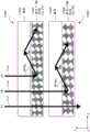
如上所述,手性(向列)相或胆甾相中的胆甾型液晶(CLC)层的液晶分子的特征在于多个液晶分子被布置为具有指向矢的连续方位角扭转,该扭转取决于膜在液晶层的法线方向或深度方向上的位置。如本文所述,被布置为具有连续方位角扭转的液晶分子在本文中统称为手性结构。如本文所述,方位角扭转或旋转的角度(φ)被描述为上述液晶分子的指向矢之间的角度,该角度是相对于与层法线平行的方向的。手性结构的液晶分子的在空间上变化的指向矢可以被描述为形成螺旋图案,其中螺距(p)被定义为如上所述指向矢旋转360°的距离(例如,在液晶层的层法线方向上)。如本文所述,被配置为衍射光栅的CLC层具有横向尺寸,通过该横向尺寸,液晶的分子结构在垂直于深度方向的横向方向上周期性地重复。横向方向上的这种周期被称为光栅周期(Λ)。As mentioned above, the liquid crystal molecules of a cholesteric liquid crystal (CLC) layer in the chiral (nematic) phase or in the cholesteric phase are characterized in that a plurality of liquid crystal molecules are arranged with a continuous azimuthal twist of the director depending on the The position of the film in the normal direction or depth direction of the liquid crystal layer. As described herein, liquid crystal molecules arranged to have a continuous azimuthal twist are collectively referred to herein as chiral structures. As described herein, the angle of azimuthal twist or rotation ([phi]) is described as the angle between the directors of the above-mentioned liquid crystal molecules relative to a direction parallel to the layer normal. The spatially varying directors of chiral-structured liquid crystal molecules can be described as forming a helical pattern, where the pitch (p) is defined as the distance over which the director rotates 360° as described above (e.g., at the layer normal of the liquid crystal layer direction). As described herein, a CLC layer configured as a diffraction grating has a lateral dimension by which a molecular structure of liquid crystal is periodically repeated in a lateral direction perpendicular to a depth direction. This period in the lateral direction is called the grating period (Λ).
根据本文描述的各种实施例,衍射光栅包括胆甾型液晶(CLC)层,该层包括多个手性结构,其中每个手性结构包括在层深度方向上延伸至少一个螺距并在第一旋转方向上连续旋转的多个液晶分子。螺距是层深度方向上的长度,其对应于手性结构的液晶分子在第一旋转方向上的一个完整旋转的净旋转角。手性结构的液晶分子的布置在与层深度方向垂直的横向方向上周期性地变化According to various embodiments described herein, the diffraction grating comprises a cholesteric liquid crystal (CLC) layer comprising a plurality of chiral structures, wherein each chiral structure comprises at least one pitch extending in the depth of the layer and at a first A plurality of liquid crystal molecules continuously rotating in the direction of rotation. The pitch is the length in the layer depth direction, which corresponds to the net rotation angle of one complete rotation of the liquid crystal molecules of the chiral structure in the first rotation direction. The arrangement of the liquid crystal molecules of the chiral structure changes periodically in the lateral direction perpendicular to the layer depth direction
图10示出了根据实施例的包括多个均匀手性结构的胆甾型液晶(CLC)层1004的横截面侧视图。CLC 1004包括CLC层1008,CLC层1008包括被布置为多个手性结构1012-1、1012-2、......1012-i的液晶分子,其中每个手性结构包括多个液晶分子,其中i是大于2的任何合适的整数。例如,手性结构1012-1包括多个液晶分子1012-1-1、1012-1-2、......1012-1-j,这些分子被布置为在层法线方向上延伸,例如,在所示的实施例中,在z方向上延伸,其中j是大于2的任何合适的整数。每个手性结构的液晶分子在第一旋转方向上连续旋转。在所示的实施例中,当在z轴的正向(即,轴箭头的方向)或入射光束1016-L、1016-R的传播方向观察时,液晶分子沿顺时针方向连续旋转。例如,在所示的实施例中,手性结构1012-1的液晶分子1012-1-1、1012-1-2、......1012-1-j例如相对于正x方向以旋转角φ1、φ2、......φj连续旋转。在所示的实施例中,为了说明的目的,在z方向上的相反两端之间的手性结构1012-1、1012-2、......1012-i中的每一者的多个液晶分子进行一个完整旋转或旋转一整圈,使得液晶分子的净旋转角为约360°。因此,手性结构1012-1、1012-2、......1012-i在z方向上具有与螺距p相同的长度L。然而,实施例不限于此,并且手性结构1012-1、1012-2、......1012-i可具有大于或小于1的任何数量的完整旋转,具有低于或高于360°的任何合适的净旋转角和/或短于或长于螺距p的在z方向上的任何合适的长度L。例如,在本文所述的各种实施例中,手性结构的完整旋转数可以在1和3之间,在2和4之间,在3和5之间,在4和6之间,在5和7之间,在6和8之间,在7和9之间,或在8和10之间,以及其它旋转数。10 shows a cross-sectional side view of a cholesteric liquid crystal (CLC)
仍然参考图10,根据一些实施例,z方向上的相邻液晶分子之间的连续旋转角φ1、φ2、......φj可以是相同的,或者根据一些其它实施例,它们可以是不同的。作为说明,在所示的实施例中,手性结构1012-1、1012-2、......1012-i的长度为约p,净旋转角为360°,使得z方向上的相邻液晶分子旋转约360°/(m-1),其中m是手性结构中的液晶分子数。例如,为了说明,手性结构1012-1、1012-2、......1012-i中的每一者具有13个液晶分子,使得z方向上的相邻液晶分子相对于彼此旋转约30°。当然,各种实施例中的手性结构可具有任何合适数量的液晶分子。Still referring to FIG. 10 , according to some embodiments, the successive rotation angles φ1, φ2, . . . φj between adjacent liquid crystal molecules in the z direction may be the same, or according to some other embodiments, they may be different. As an illustration, in the illustrated embodiment, the chiral structures 1012-1, 1012-2, ... 1012-i have a length of about p and a net rotation angle of 360° such that the phase Ortho liquid crystal molecules rotate about 360°/(m-1), where m is the number of liquid crystal molecules in the chiral structure. For example, for illustration, each of the chiral structures 1012-1, 1012-2, ... 1012-i has 13 liquid crystal molecules such that adjacent liquid crystal molecules in the z direction are rotated relative to each other by 30°. Of course, the chiral structures in various embodiments may have any suitable number of liquid crystal molecules.
因此,仍然参考图10,在横向方向(例如x方向)上相邻的手性结构具有类似地布置的液晶分子。在所示的实施例中,手性结构1012-1、1012-2、......1012-i被类似地配置,使得处于大约相同深度处的不同手性结构的液晶分子(例如最接近光入射表面1004S的液晶分子)具有相同的旋转角,以及处于大约相同深度处的连续液晶分子的连续旋转角,以及每个手性结构的液晶分子的净旋转角。Therefore, still referring to FIG. 10 , adjacent chiral structures in the lateral direction (eg, the x direction) have similarly arranged liquid crystal molecules. In the illustrated embodiment, chiral structures 1012-1, 1012-2, ... 1012-i are similarly configured such that liquid crystal molecules of different chiral structures (e.g., most Liquid crystal molecules close to the
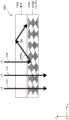
在下文中,根据实施例在操作中进一步描述图10中所示的CLC层1004。如所述的,CLC层1004包括手性结构1012-1、1012-2、......1012-i,其在横向方向(例如x方向)上具有均匀布置。在操作中,当具有左旋圆偏振的光束和具有右旋圆偏振的光束的组合的入射光入射在CLC层1008的表面1004S上时,通过布拉格反射或衍射,具有圆偏振旋向性之一的光由CLC层1004反射,而具有相反偏振旋向性的光在基本没有干扰的情况下透射通过CLC层1008。如本文和整个公开所述,旋向性被定义为在传播方向上观察。根据实施例,当光束1016-L、1016-R的偏振方向或偏振的旋向性匹配而使得它具有与手性结构1012-1、1012-2、......1012-i的液晶分子具有相同的旋转方向时,入射光被反射。如图所示,入射在表面1004S上的是具有左旋圆偏振的光束1016-L和具有右旋圆偏振的光束1016-R。在所示的实施例中,手性结构1012-1、1012-2、......1012-i的液晶分子在入射光束1016-L、1016-R传播的方向(即正x方向,该方向是与具有右旋圆偏振的光束1016-R相同的旋转方向)上连续地沿顺时针方向旋转。因此,具有右旋圆偏振的光束1016-R基本上被反射,而具有左旋圆偏振的光束1016-L基本透射通过CLC层1004。Hereinafter, the
不受任何理论的束缚,在布拉格反射或衍射条件下,入射光的波长(λ)可以与CLC层的均或平均折射率(n)以及螺距(p)成比例,在某些情况下可表示为满足以下条件:Without being bound by any theory, under Bragg reflection or diffraction conditions, the wavelength (λ) of incident light can be proportional to the average or average refractive index (n) and pitch (p) of the CLC layer, in some cases expressed as To meet the following conditions:

另外,布拉格反射或衍射波长的带宽(Δλ)可以与CLC层1004的双折射Δn(例如,不同光偏振之间的折射率差)和螺距(p)成比例,在某些情况下可表示为满足以下条件:Additionally, the bandwidth (Δλ) of the Bragg reflection or diffracted wavelengths can be proportional to the birefringence Δn (e.g., the difference in refractive index between different light polarizations) and the pitch (p) of the
Δλ=Δn·p [2]Δλ=Δn p [2]
在本文所述的各种实施例中,带宽Δλ为约60nm,约80nm或约100nm。In various embodiments described herein, the bandwidth Δλ is about 60 nm, about 80 nm, or about 100 nm.
根据各种实施例,在例如约390nm和约700nm之间的可见波长范围内,或者在例如约700nm和约2500nm之间的近红外波长范围内的峰值反射强度可以超过约60%,约70%,约80%或约90%。另外,根据各种实施例,半峰全宽(FWHM)可以小于约100nm,小于约70nm,小于约50nm或小于约20nm。According to various embodiments, the peak reflection intensity may exceed about 60%, about 70%, about 80% or about 90%. Additionally, according to various embodiments, the full width at half maximum (FWHM) may be less than about 100 nm, less than about 70 nm, less than about 50 nm, or less than about 20 nm.
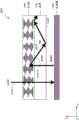
图11示出了根据实施例的CLC光栅(CLCG)1150的横截面侧视图,该CLC光栅在横向方向上具有不同地布置的手性结构,例如在横向方向上具有变化的扭转角的手性结构。类似于图10的CLC层1004,衍射光栅1150包括胆甾型液晶(CLC)层1158,CLC层1158包括被布置为多个手性结构1162-1、1162-2、......1162-i的液晶分子,其中每个手性结构包括多个液晶分子。例如,手性结构1162-1包括多个液晶分子1162-1-1、1162-1-2、......1162-1-j,这些液晶分子被布置为在层法线方向(在所示实施例中表示为z方向)上延伸。每个手性结构的液晶分子以与参考图10所述类似的方式在第一旋转方向上连续旋转。此外,手性结构的各种其它参数——包括长度L、由液晶分子做出的完整旋转次数以及每个手性结构的液晶分子数量——类似于上面关于图10描述的手性结构。11 shows a cross-sectional side view of a CLC grating (CLCG) 1150 having differently arranged chiral structures in the lateral direction, such as chiral structures with varying twist angles in the lateral direction, according to an embodiment. structure. Similar to the
然而,与图10所示的实施例形成对比,在图11所示的实施例中,在横向方向(例如x方向)上相邻的手性结构具有不同地布置的液晶分子。手性结构1162-1、1162-2、......1162-i在x方向上被不同地配置,使得处于大约相同深度处的不同手性结构的液晶分子具有不同的旋转角。例如,在所示的实施例中,手性结构1162-1、1162-2、......1162-i的最接近入射表面1158S的液晶分子1162-1-1、1162-2-1、......1162-i-1分别在相对于例如正x方向的正x轴方向上以旋转角φ1、φ2、......φi连续旋转。在所示的实施例中,跨与衍射光栅1150的周期对应的横向长度Λ最接近入射表面1158S的液晶分子1162-1-1、1162-2-1、......1162-i-1的净旋转角是约180°的旋转角。另外,设置在大约相同深度水平处的不同手性结构的液晶分子相对于各个最表面的液晶分子旋转大约相同的旋转角。However, in contrast to the example shown in FIG. 10 , in the example shown in FIG. 11 , adjacent chiral structures in the lateral direction (eg x-direction) have differently arranged liquid crystal molecules. The chiral structures 1162-1, 1162-2, ... 1162-i are configured differently in the x direction such that liquid crystal molecules of different chiral structures at about the same depth have different rotation angles. For example, in the illustrated embodiment, the liquid crystal molecules 1162-1-1, 1162-2-1 of the chiral structures 1162-1, 1162-2, ... 1162-i closest to the incident surface 1158S , . . . 1162-i-1 are continuously rotated at rotation angles φ1, φ2, . In the illustrated embodiment, the liquid crystal molecules 1162-1-1, 1162-2-1, . . . 1162-i- A net rotation angle of 1 is a rotation angle of about 180°. In addition, liquid crystal molecules of different chiral structures disposed at about the same depth level rotate about the same rotation angle with respect to the respective uppermost liquid crystal molecules.
仍然参考图11,根据一些实施例,在x方向上跨周期Λ处于相同深度水平的液晶分子的连续旋转角φ1、φ2、......φi可以是相同的,或者根据一些其它实施例,它们可以是不同的。在所示的实施例中,对于周期Λ,当净旋转角如所示实施例中那样为360°时,x方向上的相邻液晶分子旋转约360°/(m-1),其中m是周期Λ在x方向上所跨越的液晶分子的数量。例如,为了说明,跨周期Λ有7个液晶分子,使得在x方向上处于相同垂直水平(veticallevel)处的相邻液晶分子相对于彼此旋转大约30°。当然,各种实施例中的手性结构可具有任何合适数量的液晶分子。Still referring to FIG. 11 , according to some embodiments, the successive rotation angles φ1, φ2, . , they can be different. In the illustrated embodiment, for a period Λ, when the net rotation angle is 360° as in the illustrated embodiment, adjacent liquid crystal molecules in the x direction rotate about 360°/(m-1), where m is The number of liquid crystal molecules spanned by the period Λ in the x direction. For example, to illustrate, there are 7 liquid crystal molecules across the period Λ such that adjacent liquid crystal molecules at the same vetical level in the x-direction are rotated about 30° relative to each other. Of course, the chiral structures in various embodiments may have any suitable number of liquid crystal molecules.
应当理解,为了说明,CLC层1158被示出为仅具有一个周期Λ。当然,实施例不限于此,并且CLC层1158可以具有由x方向上的CLCG的横向尺寸确定的任何合适数量的周期。It should be understood that, for purposes of illustration, the
如由CLCG 1150所示,当横向方向(例如,x方向)上的手性结构被不同地布置(例如,连续旋转)时,连续旋转的手性结构引起反射光的相对相位沿x方向的变化。针对曲线图1170对此进行说明,曲线图1170绘制了由一个周期Λ内在x轴方向上以旋转角φ1、φ2、......φi连续旋转的手性结构导致的相位变化φ。不受任何理论的束缚,反射光1018的相对相位差(Δφ)可表示为Δφ(x)=(2πx/Λ),其中x是沿横向方向的位置,Λ是周期。带宽可以表示为Δλ≈Δn·p。As shown by
返回参考图10至11和等式[1]和[2],根据各种实施例,可以通过改变手性结构的螺距p来改变布拉格反射波长。在各种实施例中,不受任何理论的束缚,螺距p可以通过增大或减小螺旋扭转力(HTP)来改变,该扭转力是指手性化合物引发上述旋转角或扭转角的能力。可以通过相对于非手性化合物的量改变手性化合物的量来改变HTP。在各种实施例中,通过化学和/或机械地将手性化合物与非手性化合物(例如向列化合物)混合,布拉格反射波长以及颜色可以基于手性化合物的相对比例和螺距之间的关系而变化。在本文公开的各种实施例中,手性化合物的量与非手性化合物的量的重量比可为约20:1、10:1、5:1、4:1、3:1、2:1、1:1、1:2、1:3、1:4、1:5、1:10或约1:20。Referring back to FIGS. 10 to 11 and Equations [1] and [2], according to various embodiments, the Bragg reflection wavelength may be changed by changing the pitch p of the chiral structure. In various embodiments, without being bound by any theory, the pitch p can be changed by increasing or decreasing the helical twisting force (HTP), which refers to the ability of a chiral compound to induce the aforementioned rotation or twist angles. HTP can be varied by varying the amount of chiral compound relative to the amount of achiral compound. In various embodiments, by chemically and/or mechanically mixing a chiral compound with an achiral compound (such as a nematic compound), the Bragg reflection wavelength as well as the color can be based on the relationship between the relative proportions of the chiral compounds and the helical pitch And change. In various embodiments disclosed herein, the weight ratio of the amount of chiral compound to the amount of achiral compound can be about 20:1, 10:1, 5:1, 4:1, 3:1, 2: 1, 1:1, 1:2, 1:3, 1:4, 1:5, 1:10 or about 1:20.
在上文关于图10和11的描述中,入射光束1016-L、1016-R被示出为在平行于层法线的方向上传播,例如在z方向上传播。然而,对于各种应用,例如,如上面关于图6和7所述,在波导1182内传播的光(例如经由全内反射(TIR)传播)以一离轴角照射在耦出光学元件1282、1284、1286、1288、1290(例如,衍射光栅)上。如下所述,本文描述的衍射光栅可以被配置为使这种配置的带宽和衍射效率最大化。In the description above with respect to Figures 10 and 11, the incident light beams 1016-L, 1016-R were shown propagating in a direction parallel to the layer normal, eg in the z-direction. However, for various applications, for example, as described above with respect to FIGS. 1284, 1286, 1288, 1290 (eg, diffraction grating). As described below, the diffraction gratings described herein can be configured to maximize the bandwidth and diffraction efficiency of such configurations.
在上文关于图10和11的描述中,液晶分子被示出为未发生预倾斜。然而,实施例不限于此,并且液晶分子可以具有相对于与CLCG的主表面平行的方向(例如,相对于x-y平面)的预倾角Φ,根据一些实施例,该预倾角在约+/-60度和约+/-90度之间,或者在约+/-65度和约+/-85度之间,例如约+/-75度;在约+/-35度和约+/-65度之间或在约+/-40度和约+/-60度之间,例如约+/-50度;在约+/-10度和约+/-40度之间或在约+/-15度和约+/-35度之间,例如约+/-25度。根据一些其它实施例,预倾角Φ可以在约±15度之间或在约±10度之间或在约±5之间,例如0度。In the description above with respect to FIGS. 10 and 11 , the liquid crystal molecules were shown not to be pretilted. However, the embodiment is not limited thereto, and the liquid crystal molecules may have a pretilt angle Φ relative to a direction parallel to the main surface of the CLCG (for example, relative to the x-y plane), which according to some embodiments is in the range of about +/-60 degrees and about +/-90 degrees, or between about +/-65 degrees and about +/-85 degrees, such as about +/-75 degrees; between about +/-35 degrees and about +/-65 degrees or Between about +/-40 degrees and about +/-60 degrees, such as about +/-50 degrees; between about +/-10 degrees and about +/-40 degrees or between about +/-15 degrees and about +/- Between 35 degrees, eg about +/- 25 degrees. According to some other embodiments, the pretilt angle Φ may be between about ±15 degrees or between about ±10 degrees or between about ±5 degrees, for example 0 degrees.
被配置为以离轴入射角高带宽反射的CLCGCLCG configured for high bandwidth reflection at off-axis incident angles
图12示出了根据实施例的被配置为以一离轴入射角高带宽反射的CLC层1158的横截面侧视图。如本文所述,离轴入射角是指入射光束1216相对于层法线方向(例如,图12中的z方向)的入射角θinc,其具有非零值,从而导致反射角θ处的布拉格反射光束1220。在某些情况下,可以通过改变λ/Λ在一定程度上改变反射角。不受任何理论的限制,在某些情况下,可以基于以下关系描述离轴反射:Figure 12 shows a cross-sectional side view of a
n·sin(θ)=λ/Λ+sin(θinc) [3]n sin(θ)=λ/Λ+sin(θinc ) [3]
其中θinc是相对于层法线方向的入射角,θ是相对于层法线方向的反射角,n是反射光束在其中传播的介质的反射率。当用入射光束1216以一离轴角照射CLC层1158时,反射光谱可以朝向更短的波长移动。根据本文公开的各种实施例,比率λ/Λ可以具有0.5和0.8之间,0.6和0.9之间,0.7和1.0之间,0.8和1.1之间,0.9和1.2之间,1.0和1.6之间,1.1和1.5之间,或1.2和1.4之间的值。where θinc is the angle of incidence with respect to the layer normal direction, θ is the reflection angle with respect to the layer normal direction, and n is the reflectivity of the medium in which the reflected beam propagates. When the
不受任何理论的束缚,CLC层1158被配置为以高效率进行布拉格反射时的离轴角也可依赖于手性结构的螺距p。Without being bound by any theory, the off-axis angle at which the
图13A和13B示出了根据实施例的被配置为以一离轴入射角进行反射的CLC层的横截面侧视图。参考图13A,第一胆甾型液晶(CLC)层1358A包括具有第一螺距(p1)的第一多个手性结构。第一CLC层1358A具有第一螺距p1,使得当第一入射光束1316A以第一离轴角θinc,1被引导到CLC层1358A的入射表面时,布拉格反射最大,这导致第一反射角θ1处的第一反射光束1320A。如图所示,CLC层1358A还被配置为具有离轴入射角的第一范围1324A,在该第一范围1324A中可以获得相对高的衍射效率。第一范围1324A可以对应于一离轴入射角范围,在该范围之外,第一反射光束1320A的强度下降超过例如1/e。例如,第一范围1324A可以具有以下值:θinc,1±3°、θinc,1±5°、θinc,1±7°、θinc,1±10°或θinc,1±20°。13A and 13B illustrate cross-sectional side views of a CLC layer configured to reflect at an off-axis angle of incidence, according to embodiments. Referring to FIG. 13A, a first cholesteric liquid crystal (CLC)
参考图13B,与第一CLC层1358A不同的第二胆甾型液晶(CLC)层1358B包括第二多个手性结构,所述第二多个手性结构具有与图13A的第一CLC层1358A的第一螺距p1不同的第二螺距(p2)。Referring to FIG. 13B, a second cholesteric liquid crystal (CLC)
如图所示,第二CLC层1358B被配置为使得当第二入射光束1316B以不同于第一离轴角θinc,1的第二离轴角θinc,2被引导到CLC层1358B的入射表面时,产生具有不同于第一反射角θ1的第二反射角θ2的第二反射光束1320B。如图所示,CLC层1358B还被配置为具有离轴角的第二范围1324B,其类似于上面关于图13A描述的第一范围1324A。As shown, the
图13C示出了根据实施例的CLCG 1358的横截面侧视图,该CLCG1358包括多个CLC层,这些CLC层在堆叠配置中具有用于以多个离轴入射角以及高衍射带宽进行布拉格反射的不同螺距。根据实施例,CLCG1358包括分别在上面关于图13A和13B描述的CLC层1358A、1358B,这些CLC层1358A、1358B在彼此之上形成,例如以堆叠的配置和/或彼此接触的方式形成。可以改善或优化包括不同螺距的多个CLC层1358A、1358B的各种参数,以使得CLCG1358被配置为在比仅使用一个CLC获得的离轴角范围更宽的范围以多个离轴入射角和高衍射效率进行高效反射。例如,在所示的实施例中,可以选择p1和p2,以使得所得到的第一和第二范围1324A和1324B至少部分地重叠,以在包括第一和第二范围1324A和1324B的连续波长范围内提供高衍射效率。然而,在其它实施例中,可以将p1和p2选择为使得第一和第二范围1324A和1324B不重叠。Figure 13C shows a cross-sectional side view of a
在操作中,第一和第二CLC层1358A、1358B在彼此之上形成,使得当第一和第二入射光束1316A、1316B以第一和第二离轴角θinc1、θinc2被引导到第一CLC层1358A的入射表面时,第一入射光束1316A基本上由第一CLC层1358A以第一反射角θ1反射,而第二入射光束1358B朝向第二CLC层1358B的入射表面而基本上透射通过第一CLC层1358A,并且基本上由第二CLC层1358B以第二反射角θ2反射。应当理解,虽然为了清楚起见未示出,但是上述概念可以扩展到任何合适数量的CLC层。In operation, the first and second CLC layers 1358A, 1358B are formed on top of each other such that when the first and second incident light beams 1316A, 1316B are directed at first and second off-axis angles θinc1 , θinc2 When an incident surface of a
如本文和整个说明书中所述,“基本上透射”通过某层的光束可以指当光离开该层时入射光强度的至少20%、30%、50%、70%或90%保留下来的光。类似地,由某层“基本上反射”的光束可以指入射光强度的至少20%、30%、50%、70%或90%在反射光中保留下来的光。As used herein and throughout the specification, a light beam that is "substantially transmitted" through a layer may refer to light that retains at least 20%, 30%, 50%, 70%, or 90% of the intensity of the incident light when it leaves the layer . Similarly, a beam of light that is "substantially reflected" by a layer may refer to light in which at least 20%, 30%, 50%, 70%, or 90% of the intensity of the incident light remains in the reflected light.
仍然参考图13C,在各种实施例中,第一和第二CLC层1358A、1358B的液晶分子可以包括不同量的相同手性化合物,使得CLC层1358A、1358B具有不同的螺旋扭转力(HTP),如上所述。例如,第二CLC层1358B可以具有与第一CLC层1358A相比更高的相同手性化合物的量。在一些实施例中,螺距p可以与手性化合物相对于包含手性和非手性化合物的整体液晶化合物的分率(fraction)成反比。然而,实施例不限于此,并且第一和第二CLC层1358A、1358B可具有不同的手性化合物。Still referring to FIG. 13C, in various embodiments, the liquid crystal molecules of the first and second CLC layers 1358A, 1358B may include different amounts of the same chiral compound such that the CLC layers 1358A, 1358B have different helical twisting forces (HTPs). , as above. For example, the
另外,在各种实施例中,第一和第二CLC层1358A、1358B的液晶分子可以包括相同或不同的手性化合物,使得CLC层1358A、1358B分别具有不同的比率λ/Λ1和λ/Λ2,使得CLC层1358A、1358B可以被配置为实现不同入射角θinc1、θinc2处的高衍射效率,例如,根据等式[3]。Additionally, in various embodiments, the liquid crystal molecules of the first and second CLC layers 1358A, 1358B may include the same or different chiral compounds such that the CLC layers 1358A, 1358B have different ratios λ/Λ1 and λ/ Λ2 , such that the CLC layers 1358A, 1358B can be configured to achieve high diffraction efficiency at different angles of incidence θinc1 , θinc2 , eg, according to equation [3].
仍然参考图13C,根据一些实施例,第一和第二CLC层1358A、1358B可以直接在彼此的顶上制造。例如,第一CLC层1358A可以沉积在为第一CLC层1358A提供定向条件的定向层(alignment layer)上,并且随后,第二CLC层1358B可以沉积在第一CLC层1358B上。在这些制造条件下,第一CLC层1358A的表面可以为第二CLC层1358B提供定向条件。在一些其它实施例中,CLC层1358A、1358B中的每一者可以用单独的定向层制造。例如,第一CLC层1358A可以形成在第一定向层上,第二定向层可以形成在第一CLC层1358A上,第二CLC层1358B可以形成在第二定向层上。根据一些实施例,在形成第二定向层和/或第二CLC层1358B之前,可以在第一CLC层1358A上形成隔离层,例如薄氧化物层。在其它实施例中,两个CLC层1358A、1358B可以在不同的基板上被单独制造并随后被堆叠。在各种实施例中,可以在两个CLC层1358A、1358B之间形成中间层,例如以增强粘附性。Still referring to FIG. 13C , according to some embodiments, the first and second CLC layers 1358A, 1358B may be fabricated directly on top of each other. For example, a
以上关于具有被优化为实现不同离轴角处的最佳衍射效率的多个CLC层的CLCG描述的概念可以扩展到其它替代实施例。特别地,在一些实施例中,代替形成多个层,可以将单个CLC层配置为具有通过优化来实现不同离轴角处的最佳衍射效率的不同区域。The concepts described above for a CLCG with multiple CLC layers optimized to achieve the best diffraction efficiency at different off-axis angles can be extended to other alternative embodiments. In particular, in some embodiments, instead of forming multiple layers, a single CLC layer can be configured with different regions optimized to achieve the best diffraction efficiency at different off-axis angles.
图14示出了根据实施例的包括具有垂直区域的单个CLC层1404的CLCG 1400的横截面侧视图,这些垂直区域具有以不同垂直区域处的离轴入射角以及高衍射带宽进行布拉格反射的沿深度方向的不同螺距。CLC层1404具有多个垂直区域,这些垂直区域具有不同的参数,例如,不同的螺距,这些参数被优化以使得可以在比使用仅一个CLC层(该层在深度方向上具有均匀间距)获得的离轴角范围更宽的范围上获得高衍射效率。在所示的实施例中,单个CLC层1404包括多个垂直区域1404A、1404B、1404C和1404D,它们可以分别具有不同的螺距p1、p2、p3和p4。类似于上面关于图13C所描述的,可以选择螺距p1、p2、p3和p4,以使得多个垂直区域1404A、1404B、1404C和1404D分别被配置为实现入射角θincA、θincB、θincC和θincD处的最佳衍射效率,这分别导致在不同垂直深度上相应反射角θA、θB、θC和θD处的反射光束。此外,如上面关于图13C所述,CLC层1404还被配置为具有相应的离轴角范围,在所述离轴角范围内可以获得相对高的衍射效率。当然,虽然为了清楚起见示出了四个垂直区域,但是CLC层1404中可以包括任何合适数量的区域。此外,上面关于图13C的具有多个CLC层的CLCG1358描述的不同变化可以应用于CLCG 1400。14 shows a cross-sectional side view of a
在图14所示的实施例中,螺距p1、p2、p3和p4的值随着距入射表面1404S的深度的增加而减小,使得在深度方向(负z方向)上产生逐渐减小的螺距梯度。当随着z方向上的层深度而变化的螺距的减小率跨CLC层1404的整个厚度均匀时,可以获得表示深度与螺距之间的线性关系的曲线图1408。然而,实施例不限于此。例如,根据一些其它实施例,螺距p1、p2、p3和p4可以在任何深度处增大或减小,并且可以根据层深度而以不同的速率改变。In the embodiment shown in FIG. 14 , the values of the pitches p1 , p2 , p3 , and p4 decrease with increasing depth from the incident surface 1404S, so that a gradual Reduced pitch gradient. When the rate of decrease in pitch as a function of layer depth in the z-direction is uniform across the entire thickness of the
可以通过改变(例如,增大或减小)CLC层的不同深度处的液晶分子的螺旋扭转力(HTP)来制造具有螺距梯度的CLC层1404。通过改变手性化合物的相对量,HTP又可以在空间上变化。在各种实施例中,通过化学和/或机械地将手性化合物与非手性化合物(例如向列化合物)在不同的垂直深度处混合,垂直区域1404A、1404B、1404C和1404D的螺距可以被配置为基于手性化合物的相对分率和螺距之间的反比关系,分别实现不同的入射角θincA、θincB、θincC和θincD处的最佳衍射效率。例如,可以使用在UV辐射下以不同反应速率进行聚合过程的不同化学组分(例如,手性双丙烯酸酯单体和向列/非手性单丙烯酸酯单体)的混合物。附加地或替代地,通过改变CLC层的不同深度处的UV辐射的照射条件(包括曝光强度和/或曝光时间),可以使HTP在空间上变化。还可以通过改变UV聚合过程的前/后处理(包括UV辐射之前、之后和/或期间的热处理)而使HTP在空间上变化。例如,当将UV吸收染料添加到混合物中时,可以产生CLC层的不同深度处的UV光的强度梯度。例如,由于UV强度梯度,与CLC层的底部区域相比,表面附近的聚合可以以更快的速率进行。例如,当胆甾组分是双丙烯酸酯时,被并入到所得聚合物中的可能性可以高得多,例如,是向列单丙烯酸酯被并入到聚合物中的可能性的两倍高。在某些情况下,如果控制总聚合速率,使得CLC层的表面区域附近的手性双丙烯酸酯的消耗在CLC层的深度方向上产生双丙烯酸酯浓度梯度。这反过来使双丙烯酸酯开始向CLC层的表面区域扩散。完全光聚合后的结果可以是CLC层的表面区域包含更多手性材料,因此与CLC层的底部区域(其包含相对大量的非手性化合物)相比具有更短螺距。在某些其它情况下,UV辐射之前/之后或期间的热处理可以被添加到聚合过程中以控制螺距梯度。因此,通过在有或没有热处理的情况下控制两种不同液晶单体之间的比率和/或不同深度处的UV辐射的剂量,可以沿CLC层的深度方向实现螺距梯度。The
对于某些应用,可能希望使衍射光栅具有某些光学特性(例如偏角衍射效率、折射率、波长选择性、偏振选择性和相位选择性以及其它参数)沿着与层法线方向正交的横向方向变化。例如,当光栅与波导堆叠时(例如,如上面关于图6和7所示),希望有横向变化,使得光在横向方向上传播。然而,在这种配置下,光的强度可能随着其在波导(例如,图7中的1182)内传播而衰减。例如,还可能希望这样的配置,以有意地使光强度跨光栅(例如,图7中的1282)偏斜(skew),从而适应与人眼相关联的感测效率的空间和/或角度变化,以最大化用户体验。因此,需要具有在空间上变化的光学特性的光学元件,例如衍射光栅。For some applications, it may be desirable to have a diffraction grating with certain optical properties (such as off-angle diffraction efficiency, refractive index, wavelength selectivity, polarization selectivity, and phase selectivity, among other parameters) along the direction normal to the layer. Lateral orientation changes. For example, when a grating is stacked with a waveguide (eg, as shown above with respect to Figures 6 and 7), lateral variation is desired such that light propagates in a lateral direction. However, in this configuration, the intensity of the light may attenuate as it propagates within the waveguide (eg, 1182 in Figure 7). For example, it may also be desirable to configure such a configuration to intentionally skew the light intensity across the grating (e.g., 1282 in FIG. 7 ) to accommodate spatial and/or angular variations in sensing efficiency associated with the human eye. , to maximize the user experience. Therefore, optical elements with spatially varying optical properties, such as diffraction gratings, are required.
图15示出了根据实施例的包括具有横向区域的CLC层的CLCG的横截面侧视图,这些横向区域具有用于在空间上变化的布拉格反射的沿横向方向的不同螺距。CLC层1424具有多个横向区域,这些横向区域具有不同的液晶材料参数(例如螺距),使得可以获得横向变化的特性,例如用于布拉格反射的横向变化的离轴入射角。在所示的实施例中,CLC层1424包括多个横向区域1424A、1424B和1424C,每个横向区域具有周期Λ并且具有相应的螺距p1、p2和p3。可以选择螺距p1、p2和p3,使得多个垂直区域1424A、1424B和1404C被配置用于不同离轴入射角θincA、θincB和θincC处的最佳衍射效率,这分别导致相应的反射角θA、θB和θC处的反射光。此外,如上面关于图13C所述,CLC层1424的不同横向区域还被配置为具有相似的相应离轴角范围,在这些离轴角范围中可以获得相对高的衍射效率。当然,虽然为了清楚起见示出了三个垂直区域,但是在CLC层1424中可以包括任何合适数量的区域。15 shows a cross-sectional side view of a CLCG comprising a CLC layer with lateral regions with different pitches in the lateral direction for spatially varying Bragg reflections, according to an embodiment. The
在图15所示的实施例中,螺距p1、p2和p3的大小可以在横向方向上单调变化,从而产生螺距的梯度。当x方向上的螺距变化率在CLC层1424的宽度或长度上均匀时,可以获得长度或宽度和螺距之间的线性关系,如表示a的图形1428所示。然而,实施例不限于此。例如,根据各种其它实施例,螺距p1、p2和p3可以在任何横向位置处增大或减小,并且可以沿着长度或宽度在x方向上以不同的速率改变。In the embodiment shown in Fig. 15, the magnitudes of the pitchesp1 ,p2 andp3 may vary monotonically in the transverse direction, thereby creating a gradient of the pitches. When the rate of pitch change in the x-direction is uniform across the width or length of the
根据各种实施例,可以通过例如液晶分子的在空间上变化的定向特性或其它材料特性来将CLC层制造为具有在横向上变化的衍射特性。例如,以上文关于图14描述的类似方式,例如通过控制两种不同液晶单体之间的比率和/或不同横向区域中的UV辐射剂量,可以实现沿横向尺寸的横向螺距梯度。According to various embodiments, the CLC layer may be fabricated to have laterally varying diffractive properties by eg spatially varying orientation properties of liquid crystal molecules or other material properties. For example, a lateral pitch gradient along the lateral dimension can be achieved in a similar manner to that described above with respect to Figure 14, for example by controlling the ratio between the two different liquid crystal monomers and/or the UV radiation dose in the different lateral regions.
波导与CLCG耦合以实现波长选择性光耦合Waveguide coupled with CLCG for wavelength selective optical coupling
如上文所述,对于包括光的耦入和耦出的各种应用,波导装置可以被配置为经由全内反射(TIR)传播光。图16示出了光学波导装置1600的示例,其包括被耦合到CLCG 1150的波导1604。CLCG 1150包括以与上文关于图11描述的手性结构1162-1、1162-2、......1162-i类似的方式被布置为多个手性结构的液晶分子。波导1604被设置在CLCG1150上方并被光学耦合到CLCG 1150。当椭圆/圆偏振入射光1016-R/L具有与手性结构的液晶分子的旋转方向相匹配的偏振旋向性时,入射光1016-R/L由CLCG1150进行布拉格反射,并以一角度被耦合到波导1604中,使得耦合光经由全内反射(TIR)在横向方向(例如,x方向)上传播。不受任何理论的束缚,当衍射角θ大于波导的临界角θC时,可以满足TIR条件。在一些情况下,TIR条件可被表示为:As noted above, for various applications involving incoupling and outcoupling of light, the waveguide arrangement may be configured to propagate light via total internal reflection (TIR). FIG. 16 shows an example of an
sin(θC)=1/nt [4]sin(θC )=1/nt [4]
其中nt是波导1604的折射率。根据各种实施例,nt可以在约1和约2之间,在约1.4和约1.8之间,或者在约1.5和约1.7之间。例如,波导可以包括聚合物,例如聚碳酸酯或玻璃。where nt is the refractive index of the
图17A示出了第一光学波导装置1700A,该光学波导装置包括第一波导1704A,第一波导1704A被耦合到第一CLCG 1750A并且被配置为当θ>θc3时经由全内反射(TIR)传播具有第三波长λ3的光。第一CLCG 1750A具有第一周期Λ1和第一螺距p1。根据一些实施例,第一波导装置1700A可以被配置为经由TIR传播可见光谱(例如,波长在约400nm和700nm之间)内的光。根据一些其它实施例,第一波导装置1700A可以被配置为经由TIR传播红外光谱(例如,波长在约700nm和1400nm之间的光谱的近红外部分)内的光。如上面关于图10和11所述,布拉格反射发生在由上文的等式[1]表示的波长处,以及由上文的等式[2]表示的波长Δλ的带宽内。例如,第一CLCG 1750A可以被设计为经由TIR耦合第三入射光1736,第三入射光1736具有蓝色(例如约450nm)、绿色(例如约550nm)、红色(例如约650nm)之一或红外中的第三波长λ3。如图所示,当Δλ为约60nm、约80nm或约100nm时,如上文所述,具有第一和第二波长λ1、λ2的第一光和第二光1716和1726基本上被透射,这是因为对于这些由于不满足等式[4]而未被耦入到第一波导1704中的颜色,不满足等式[1]。Figure 17A shows a first
图17B示出了与上面关于图17A所示的第一光学波导装置1700A组合的第二光学波导装置1700B。光学波导装置1700B在光路中被设置在光学波导装置1700A之后,并且包括第二波导1704B,第二波导1704B被耦合到第二CLCG 1750B并且被配置为当θ>θc2时经由全内反射(TIR)传播具有第二波长λ2的光1726。第二CLCG 1750B具有第二周期Λ2和第二螺距p2。如上面关于图17A所述,具有第一和第二波长λ1、λ2的第一和第二光1716和1726基本上透射通过第一光学波导装置1700A。在所透射的第一和第二光1716和1726中,第二CLCG 1750B可以被设计为当θ>θc2时经由TIR耦合第二入射光1726,第二入射光1726具有在蓝色(例如,约450nm)、绿色(例如,约550nm)、红色(例如,约650nm)或红外之一中透射的第二波长λ2。因此,如图所示,当Δλ为约60nm、约80nm或约100nm时,如上文所述,具有第一波长λ1的第一光1716基本上进一步透射通过第二波导装置1700B。Figure 17B shows a second
图17C示出了与上面关于图17B所示的第一和第二光学波导装置1700A和1700B组合的第三光学波导装置1700C。第三光学波导装置1700C在光路中被设置在第一和第二光学波导装置1700A和1700B之后,并且包括第三波导1704C,第三波导1704C被耦合到第三CLCG1750C并且被配置为当θ>θc1时经由全内反射(TIR)传播具有第一波长λ2的第一光1716。第三CLCG 1750C具有第三周期Λ3和第三螺距p3。如上面关于图17B所述,具有第一波长λ1的第一光1716基本上透射通过第一和第二波导装置1700A和1700B。第三CLCG 1750C可以被设计为当θ>θc1时经由TIR耦合第一入射光1716,第一入射光1716具有在蓝色(例如,约450nm)、绿色(例如,约550nm)、红色(例如,约650nm)或红外之一中透射的第一波长λ1。因此,如图所示,当Δλ为约60nm、约80nm或约100nm时,如上文所述,因为满足等式[4],具有第一波长λ1的第一光1716基本上被耦合到第三波导1704C中。Figure 17C shows a third optical waveguide device 1700C combined with the first and second
因此,如上面关于图17A至17C所述,通过将第一、第二和第三光学波导装置1700A,1700B和1700C中的一者或多者放置在相同的光路中,具有不同波长λ1、λ2和λ3的第一、第二和第三光1716、1726和1736中的一者或多者可以被耦合而分别在第一、第二和第三波导1704A、1704B和1704C之一中经由TIR传播。虽然在图17A至17C中的每一者中,第一至第三光学波导装置1704A、1704B和1704C中的每一者分别具有专用的第一至第三波导1704A、1704B和1704C以及专用的第一至第三CLCG 1750A、1750B和1750C,但实施例不限于此。例如,单个波导可以经由TIR耦合来自多个CLCG的堆叠的布拉格反射光,如下文关于图18所示。此外,也可以组合大于三个(或小于三个)的任何合适数量的光学波导装置来通过布拉格反射进行进一步的选择性耦合。Thus, by placing one or more of the first, second and third
图18示出了光学波导装置1800,该光学波导装置包括被耦合到多个CLCG 1750的公共波导1704。多个CLCG 1750被配置为堆叠,该堆叠包括第一至第三CLCG 1750A至1750C并且被配置为经由全内反射(TIR)分别传播具有第三,第二和第一波长λ3、λ2和λ1的第三、第二和第一光1736、1726和1716。当第三、第二和第一光1736、1726和1716中的一者或多者分别满足条件θ>θc3、θ>θc2和θ>θc1时,以与上述关于图17A至17C描述的类似方式发生TIR。同样以类似的方式,第一、第二和第三CLCG 1750A、1750B和1750C被配置为当θ>θc3、θ>θc2和θ>θc1时分别选择性地布拉格反射第三、第二和第一光1736、1726和1716。当然,可以堆叠小于或大于三个(或小于三个)的任何合适数量的CLCG来通过布拉格反射进行进一步的选择性耦合。因此,与上面关于图17B和17C描述的实施例相比,通过采用公共波导1704可以获得更紧凑的波导装置1800。而且,代替三个不同的CLCG层(如图18所示),CLCG层的堆叠可以被布置为具有螺距梯度(包括从p1到p3的范围)的单个(或多个)层。FIG. 18 shows an
如上面关于图17A至18所述,第一至第三CLCG 1750、1750B、1750C分别具有第一至第三周期Λ1、Λ2和Λ3以及第一至第三螺距p1、p2和p3。在各种实施例中,每个CLCG可以被配置为使得波长/周期比λ/Λ在约0.3和2.3之间,在约0.8和1.8之间,或在约1.1和约1.5之间,例如约1.3。或者,与CLCG被配置用于布拉格反射的相应波长(λ)相比,周期(Λ)可以被配置为较小,减小的幅度在约1nm和250nm之间,在约50nm和200nm之间,或在约80nm和170nm之间。例如,当λ1、λ2和λ3在可见光范围内(例如,分别为约620nm至约780nm,例如约650nm(红色);约492nm至约577nm,例如550nm(绿色),以及约435nm至约493nm,例如约450nm(蓝色))时,相应的周期Λ1、Λ2和Λ3可以分别为约450nm至约550nm,例如约500nm;约373nm至约473nm,例如约423nm;以及约296nm至约396nm,例如约346nm。或者,当λ1、λ2和λ3在红外范围内(例如,在约750nm至约1400nm之间的近红外范围内,例如约850nm)时,相应的周期Λ1、Λ2和Λ3可以为约975nm至约1820nm,例如约1105nm。另外,在各种实施例中,每个CLCG可以被配置为使得波长/螺距比λ/p在约0.6和2.6之间,在约1.1和2.1之间,或在约1.4和约1.8之间,例如约1.6。或者,与CLCG被配置用于布拉格反射的相应波长(λ)相比,螺距(p)可以被配置为较小,减小的幅度在约50nm至350nm之间,在约100nm至300nm之间,或在约140nm至280nm之间。例如,当λ1、λ2和λ3分别为约620nm至约780nm,例如约650nm(红色);约492nm至约577nm,例如550nm(绿色),以及约435nm至约493nm,例如约450nm(蓝色))时,相应的螺距p1、p2和p3可以分别为约350nm至约450nm,例如约400nm;约290nm至约390nm,例如约340nm;以及约230nm至约330nm,例如约280nm。或者,当λ1、λ2和λ3在红外范围内(例如,在约750nm至约1400nm之间的近红外范围内,例如约850nm)时,相应的周期Λ1、Λ2和Λ3可以为约1200nm至约2240nm,例如约1360nm。As described above with respect to FIGS. 17A to 18 , the first to
波导与CLCG和反射镜耦合以实现波长选择性光耦合Waveguides coupled with CLCG and mirrors for wavelength selective optical coupling
图19示出了光学波导装置1900,该光学波导装置包括被耦合到CLCG1150的波导1604,其类似于上文关于图16描述的光学波导装置。如上文关于图10和11所述,在操作中,当椭圆/圆偏振入射光的偏振旋向性具有与CLCG 1150的手性结构的液晶分子相同的旋转方向时,CLCG 1150基本上反射入射光。如图所示,入射在表面1050S上的是具有左旋圆偏振的光束1016-L和具有右旋圆偏振的光束1016-R。在所示的实施例中,当观察入射光束1016-L、1016-R传播的方向(即负z方向)时,手性结构的液晶分子沿顺时针方向连续旋转,使得液晶分子的旋转方向与具有右旋圆偏振的光束1016-R的旋向性相匹配。因此,具有右旋圆偏振的光束1016-R基本上被CLCG 1150反射,而具有左旋圆偏振的光束1016-L基本上透射通过CLCG 1150。FIG. 19 shows an
对于某些应用,可能希望在类似于上面关于图19所述的耦入波导装置之前使椭圆或圆偏振光的偏振旋向性翻转。这种出现这种情况:例如,入射的椭圆或圆偏振光的偏振旋向性与CLCG中的手性结构的旋转方向不匹配,使得CLCG不被配置为按照上文所述使光布拉格反射以耦入到波导内。对于一些其它应用,由于入射的椭圆或圆偏振光的偏振旋向性与CLCG中的手性结构的旋转方向之间缺乏匹配,可能希望回收透射通过CLCG的光。为了解决这些和其它需求,在下文中,公开了采用偏振转换反射器来满足这些需求的波导装置的各种实施例。For some applications, it may be desirable to flip the polarization handedness of elliptically or circularly polarized light prior to coupling into a waveguide arrangement similar to that described above with respect to FIG. 19 . This arises when, for example, the polarization handedness of incident elliptically or circularly polarized light does not match the direction of rotation of the chiral structures in the CLCG such that the CLCG is not configured to Bragg reflect light as described above to coupled into the waveguide. For some other applications, it may be desirable to recycle light transmitted through the CLCG due to the lack of match between the polarization handedness of incident elliptically or circularly polarized light and the direction of rotation of the chiral structures in the CLCG. To address these and other needs, hereinafter, various embodiments of waveguide arrangements employing polarization converting reflectors to meet these needs are disclosed.
图20示出了根据实施例的光学波导装置2000,该光学波导装置包括被耦合到CLCG1604的波导1150和偏振转换反射器2004,其中CLCG1604被配置为接收入射光,波导1150被配置为经由全内反射(TIR)传播从CLCG布拉格反射的光。偏振转换反射器2004被配置为使得:在入射的椭圆或圆偏振光从该偏振转换反射器2004反射时,该入射的椭圆或圆偏振光的偏振旋向性被翻转为相反的偏振旋向性(例如,左旋到右旋,或者右旋到左旋)。波导装置2000类似于上面关于图19描述的波导装置1900,但不被配置为首先接收通过波导1150的入射光束,波导装置2000而是被配置为首先接收通过CLCG 1604的具有例如左旋圆偏振的入射光束2016-L。当在入射光束2016-L的传播方向(负z方向)上观察时,入射光束2016-L具有与CLCG 1604中的手性结构的旋转方向不匹配的偏振旋向性,使得它不被CLCG 1604布拉格反射。因此,入射光束2016-L基本上透射通过CLCG 1604,随后被偏振转换反射器2004反射。具有例如右旋圆偏振的反射光束2016-R由此成为波导1150的表面1150S上的入射光束。由于翻转的偏振旋向性,当在反射光束2016-R的传播方向(正z方向)上观察时,现在入射在波导1150的表面1150S上的反射光束2016-R具有与CLCG 1604中的手性结构的旋转方向匹配的偏振旋向性,使得它被CLCG1604布拉格反射。作为以相对于层法线方向(z轴)的角θ>θc反射的另一反射光束2018而被反射的反射光束2016-R在横向方向(例如,x方向)上耦合到并传播通过波导1150。20 shows an
图21A示出了在入射光束2116线性偏振或非偏振的情况下的上面关于图20描述的光学波导装置2000,其中每种情况下的入射光束2116可被视为既包括左旋圆偏振分量也包括右旋圆偏振分量。在这样的情况下,入射光束2116可以经由TIR在相反的横向方向上被耦入到波导内。例如,类似于上面关于图20所描述的,入射光束2116的具有与CLCG 1604中的手性结构的旋转方向不匹配的偏振旋向性(例如,左旋)的分量基本上透射通过CLCG 1604并随后被偏振转换反射器2004反射,以发生偏振旋向性翻转,例如翻转到右旋,并且在第一横向方向(例如,正x方向)上被耦入到波导1150内并且传播通过波导1150。另一方面,类似于上面关于图19所描述的,入射光束2116的具有与CLCG 1604中的手性结构的旋转方向匹配的偏振旋向性(例如,右旋)的分量基本上直接被CLCG 1604反射,并且随后在与第一横向方向相反的第二横向方向(例如,负x方向)上被耦入到波导1150内并且传播通过波导1150。21A shows the
图21B示出了在入射光被偏振成两个正交的椭圆或圆偏振光束(例如,具有左旋圆偏振的光束1016-L和具有右旋圆偏振的光束1016-R)的情况下的上面关于图21A描述的光学波导装置2000。在这样的情况下,入射光束1016-L、1016-R可以经由TIR被耦入到一波导内以在相反的横向方向上传播,其方式与上文关于图21A所述的方式类似。例如,具有与CLCG1604中的手性结构的旋转方向不匹配的偏振旋向性(例如,左旋)的光束1016-L基本上透射通过CLCG 1604并且随后被偏振转换反射器2004反射,以发生偏振旋向性翻转,例如翻转到右旋,并且在第一横向方向(例如,正x方向)上被耦入到波导1150内并且传播通过波导1150。另一方面,具有与CLCG 1604中的手性结构的旋转方向匹配的偏振旋向性(例如,右旋)的入射光束1016-R基本上直接被CLCG 1604反射,并且随后在与第一横向方向相反的第二横向方向(例如,负x方向)上被耦入到波导1150内并且传播通过波导1150。FIG. 21B shows the top view in the case where the incident light is polarized into two orthogonal elliptically or circularly polarized beams (e.g., beam 1016-L with left-handed circular polarization and beam 1016-R with right-handed circular polarization). The
图22A示出了根据实施例的光学波导装置2200,该光学波导装置2200包括被耦合到多个CLCG的公共波导2204,所述多个CLCG例如被布置为堆叠,该堆叠包括第一CLCG 2204和第二CLCG 2208,第一CLCG 2204的手性结构具有第一旋转方向,第二CLCG 2208的手性结构具有与第一旋转方向相反的第二旋转方向。如上文关于各种实施例所述,在操作中,当入射光束的偏振方向的方向与CLCG的手性结构的液晶分子的旋转方向匹配时,入射光被反射。所示的光学波导装置2200处于入射光束2116线性偏振或非偏振的状态。在这样的情况下,入射光束2116可以在两个相反的横向方向(正x方向和负x方向)上都经由TIR被耦入到波导内。在所示的实施例中,当在入射光2116传播的方向(即,负z方向)上观察时,第一CLCG2204的手性结构的液晶分子沿顺时针方向连续旋转,而第二CLCG 2204的手性结构的液晶分子在相反的逆时针方向上连续旋转。22A shows an
仍然参考图22A,椭圆或圆形入射光束2116的具有与第一CLCG 2204的手性结构的旋转方向(例如,顺时针方向)匹配的第一偏振旋向性的分量(例如,右旋偏振分量)基本上被第一CLCG 2204反射,从而以相对于层法线方向(z轴)的角θ>θc1产生第一反射光束2118A,并且在第一横向方向(例如,正x方向)上耦合到公共波导2204并传播通过公共波导2204。Still referring to FIG. 22A , the elliptical or
仍然参考图22A,另一方面,椭圆或圆形入射光束2116的具有与第一CLCG 2204的手性结构的旋转方向不匹配的第二偏振旋向性的分量(例如,左旋偏振分量)基本上透射通过第一CLCG 2204。在透射通过第一CLCG2204之后,具有与第二CLCG 2208的手性结构的旋转方向(例如,逆时针方向)不匹配的第二偏振旋向性2116的椭圆或圆形入射光束2116基本上被第二CLCG 2208反射,从而以相对于层法线方向(z轴)的角θ>θc2产生第二反射光束2118B,并且在第二横向方向(例如,负x方向)上耦合到公共波导2204内并传播通过公共波导2204。Still referring to FIG. 22A , on the other hand, the component of the elliptical or
图22B示出了在入射光被偏振成两个正交的椭圆或圆偏振光束(例如,具有例如左旋椭圆/圆偏振的光束1016-L和具有例如右旋椭圆/圆偏振的光束1016-R)的另一情况下的上面关于图22A描述的光学波导装置2000。在这样的情况下,入射光束1016-L、1016-R可以在相反的横向方向上经由TIR被耦入到公共波导2204内,其方式与上文关于图22A所述的用于耦合具有第一和第二偏振旋向性(例如,左旋和右旋)的入射光束1016-L、1016-R的方式类似。FIG. 22B shows that a beam 1016-L has, for example, a left-handed elliptical/circular polarization and a beam 1016-R has, for example, a right-handed elliptical/circular polarization. ) in another case of the
以上关于图21B和22B描述的实施例在某些应用(例如,其中不同的光信号(即图像)以正交的圆偏振被编码)中可以是特别有利的。在这种情况下,取决于偏振旋向性,光可以被耦入到相反的方向(例如,正x方向和负x方向)。The embodiments described above with respect to FIGS. 21B and 22B may be particularly advantageous in certain applications (eg, where different optical signals (ie, images) are encoded with orthogonal circular polarizations). In this case, depending on the polarization handedness, light can be coupled into opposite directions (eg, positive x-direction and negative x-direction).
图22C示出了根据实施例的光学波导装置2220,该光学波导装置2220包括被耦合到多个CLCG的公共波导2250,例如,所述多个CLCG被布置为堆叠,该堆叠包括第一CLCG2204和第二CLCG 2208,第一CLCG2204的手性结构具有第一旋转方向,第二CLCG 2208的手性结构具有与第一旋转方向相反的第二旋转方向。与关于图22A和22B描述的实施例不同,在波导装置2220中,公共波导2250被插在第一和第二CLCG层2204、2208之间。为了说明,所示的光学波导装置2220处于入射光束2116线性偏振或非偏振的状态。在这样的情况下,入射光束2116可以在相反的横向方向上经由TIR被耦入波导内。在所示的实施例中,当观察入射光2116传播的方向(即负z方向)时,第一CLCG 2204的手性结构的液晶分子沿顺时针方向连续旋转,而第二CLCG 2204的手性结构的液晶分子沿相反的逆时针方向连续旋转。当然,相反的布置也是可能的。22C shows an
仍然参考图22C,椭圆或圆形入射光束2116的具有与第一CLCG 2204的手性结构的旋转方向(例如,顺时针方向)匹配的第一偏振旋向性的分量(例如,右旋偏振分量)基本上被第一CLCG 2204反射,从而以相对于层法线方向(z轴)的角θ>θc1产生第一反射光束2118A,该第一反射光束2118A接着反射离开第一CLCG 2204的外表面,然后再在第一横向方向(例如,负x方向)上经由TIR耦合到公共波导2250内并传播通过公共波导2250。Still referring to FIG. 22C , the elliptical or
仍然参考图22C,另一方面,椭圆或圆形入射光束2116的具有与第一CLCG 2204的手性结构的旋转方向(例如,顺时针方向)不匹配的第二偏振旋向性的分量(例如,左旋偏振分量)基本上透射通过第一CLCG 2204,并进一步通过公共波导2204,然后基本上被第二CLCG 2208反射,从而以相对于层法线方向(z轴)的角θ>θc2产生第二反射光束2218B,并且在第二横向方向(例如,正x方向)上经由TIR耦合到公共波导2250并传播通过公共波导2250。Still referring to FIG. 22C , on the other hand, the elliptical or
胆甾型液晶离轴反射镜Cholesteric Liquid Crystal Off-Axis Mirrors
如上文关于各种实施例所述,通过使入射的椭圆或圆偏振光的偏振旋向性与CLC层的手性结构的液晶分子的旋转方向相匹配,可以将CLC层配置为布拉格反射器。此外,具有不同螺距的一个或多个CLC层可以被配置为具有高带宽的波长选择性布拉格反射器。基于本文关于各种实施例描述的概念,CLC层可被配置为离轴反射镜,该离轴反射镜被配置为选择性地反射第一波长范围,例如,红外波长(例如,近红外波长),同时透射另一波长范围,例如可见波长。在下文中,根据实施例,公开了在眼睛跟踪系统中实现的CLC离轴反射镜的各种实施例的应用。As described above with respect to various embodiments, the CLC layer can be configured as a Bragg reflector by matching the polarization handedness of incident elliptically or circularly polarized light to the direction of rotation of the liquid crystal molecules of the chiral structure of the CLC layer. Furthermore, one or more CLC layers with different pitches can be configured as wavelength selective Bragg reflectors with high bandwidth. Based on the concepts described herein with respect to various embodiments, the CLC layer can be configured as an off-axis mirror configured to selectively reflect a first wavelength range, e.g., infrared wavelengths (e.g., near-infrared wavelengths) , while transmitting another wavelength range, such as visible wavelengths. In the following, according to an embodiment, the application of various embodiments of the CLC off-axis mirror implemented in an eye tracking system is disclosed.
图23示出了根据各种实施例的采用胆甾型液晶反射器(CLCR)(例如,被配置为对观看者的眼睛302进行成像的波长选择性CLCR 1150)的眼睛跟踪系统2300的示例。眼睛跟踪可以是交互式视觉或控制系统中的关键特征,该交互式视觉或控制系统包括可穿戴显示器,例如图2中的可穿戴显示系统200或图24A至24H中描述的系统700,用于虚拟/增强/混合现实显示应用以及其它应用。为了实现良好的眼睛跟踪,可能需要以低透视角度获得眼睛302的图像,为此可能需要将眼睛跟踪相机702b设置在观看者眼睛的中心位置附近。然而,相机702b的这种定位可能干扰用户的视线。或者,可以将眼睛跟踪相机702b设置在较低位置或一侧。然而,由于以较陡的角度捕获眼睛图像,因此相机的这种定位可能增加获得稳健和精确的眼睛跟踪的难度。通过将CLCR 1150配置为选择性地从眼睛302反射红外(IR)光2308(例如,具有850nm的波长),同时透射来自世界(如图4所示)的可见光2304,可以在以法线视角或低视角捕获眼睛图像的同时将相机702b放置在远离用户视线的位置。由于可见光未被反射,因此这种配置不会干扰用户的视线。如图所示,相同的CLCR 1150也可以被配置为IR照射源2320。IR照射器的低视角可以导致较少的遮挡(occlusion),例如来自眼睫毛的遮挡,这种配置允许更稳健地检测镜面反射,这可以是现代眼睛跟踪系统中的关键特征。23 illustrates an example of an eye-tracking
仍然参考图23,根据各种实施例,如上文所述,CLCR 1150包括一个或多个胆甾型液晶(CLC)层,每个CLC层包括多个手性结构,其中每个手性结构包括在层深度方向(例如,z方向)上延伸并在第一旋转方向上连续旋转的多个液晶分子。手性结构的液晶分子的布置在与层深度方向垂直的横向方向上周期性地变化,使得一个或多个CLC层被配置为基本上布拉格反射具有第一波长(λ1)的第一入射光,同时基本上透射具有第二波长(λ2)的第二入射光。如本说明书中其它地方所述,一个或多个CLC层中的每一者被配置为当在层深度方向上观察时,基本上布拉格反射具有与第一旋转方向匹配的偏振旋向性的椭圆或圆偏振的第一和第二入射光,同时被配置为当在层深度方向上观察时,基本上透射具有与第一旋转方向相反的偏振旋向性的椭圆或圆偏振的第一和第二入射光。根据实施例,在横向方向上周期性变化的液晶分子的布置被布置为在横向方向上具有周期,使得第一波长和周期之间的比率在约0.5和约2.0之间。根据实施例,第一波长在约600nm和约1.4μm之间的近红外范围内,例如约850nm,并且第二波长在具有本说明书中的其它地方描述的一种或多种颜色的可见光范围内。根据实施例,手性结构的液晶分子相对于与层深度方向垂直的方向预倾斜。如所配置的,一个或多个CLC层被配置为使得第一入射光以相对于层深度方向(z方向)的角(θR)反射,基于例如上文描述的等式[3],该角相对于层深度方向超过约50°、约60°、约70°或约80°。Still referring to FIG. 23 , according to various embodiments, as described above,
返回参考图2,头戴式显示器(HMD)(例如,图2中的可穿戴显示系统200)的穿戴者的眼睛可以使用反射性离轴衍射光学元件(DOE)而被成像,该反射性离轴衍射光学元件例如可以是全息光学元件(HOE)。所得到的图像可被用于跟踪一只或两只眼睛,对视网膜进行成像,在三维中重建眼睛形状,从眼睛提取生物信息(例如,虹膜识别)等。Referring back to FIG. 2 , the eyes of a wearer of a head-mounted display (HMD) (eg, wearable display system 200 in FIG. 2 ) can be imaged using a reflective off-axis diffractive optical element (DOE), which The axis diffractive optical element may for example be a holographic optical element (HOE). The resulting images can be used to track one or both eyes, image the retina, reconstruct the shape of the eye in 3D, extract biological information from the eye (eg, iris recognition), etc.
头戴式显示器(HMD)使用关于穿戴者眼睛状态的信息的原因有多种。例如,该信息可被用于估计穿戴者的注视方向或用于生物识别。然而,这个问题具有挑战性,因为HMD和穿戴者的眼睛之间的距离很短。由于注视跟踪需要更大的视野,同时生物识别需要在虹膜上的目标上具有相对大量的像素,导致该问题进一步复杂化。对于试图实现这两个目标的成像系统,这两个任务的要求在很大程度上是不一致的。最后,眼睑和睫毛的遮挡使这两个问题进一步复杂化。本文描述的成像系统的实施例解决了这些问题中的一些或全部。本文关于图24A至24F描述的成像系统700的各种实施例可与包括本文描述的显示设备的HMD(例如,图2所示的可穿戴显示系统200和/或图6所示的显示系统1000)一起使用。There are several reasons why a head-mounted display (HMD) uses information about the state of the wearer's eyes. For example, this information could be used to estimate the wearer's gaze direction or for biometric identification. However, this problem is challenging due to the short distance between the HMD and the wearer's eyes. This problem is further complicated by the fact that gaze tracking requires a larger field of view, while biometric recognition requires a relatively large number of pixels on the target on the iris. For an imaging system that attempts to achieve both goals, the requirements of these two tasks are largely at odds. Finally, occlusion by eyelids and eyelashes further complicates both issues. Embodiments of the imaging systems described herein address some or all of these issues. Various embodiments of the
图24A示意性地示出了成像系统700的示例,该成像系统700包括成像器702b,成像器702b被用于观察眼睛304并且被安装在穿戴者的太阳穴附近(例如,位于图2中的可穿戴显示系统200的框架64上,例如位于耳柄上)。在其它实施例中,第二成像器被用于穿戴者的另一只眼睛302,使得每只眼睛被单独成像。成像器702b可以包括对红外辐射敏感的红外数字相机。成像器702b被安装为面向前方(在穿戴者的视线方向上),而不是面向后方并指向眼睛304(如与图6所示的相机500一起使用)。通过将成像器702b设置为更靠近穿戴者的耳朵,成像器702b的重量也更靠近耳朵,并且与其中成像器朝后并且被设置为更靠近HMD的前方(例如,接近图2中的显示器62)的HMD相比,该HMD更容易穿戴。另外,通过将前向成像器702b放置在穿戴者的太阳穴附近,从穿戴者的眼睛304到成像器的距离大约是设置在HMD前面附近的后向成像器的两倍(例如,与图4所示的相机500相比)。由于图像的景深与该距离大致成比例,因此前向成像器702b的景深大约是后向成像器的两倍。成像器702b的较大景深有利于对具有大的或突出的鼻子、眉骨等的穿戴者的眼睛区域进行成像。FIG. 24A schematically illustrates an example of an
成像器702b被定位为观察其它透明光学元件706的内表面704。光学元件706可以是HMD的显示器708的一部分(或一副眼镜中的镜片)。光学元件706可以透射入射在光学元件上的可见光的至少10%、20%、30%、40%、50%或更多。在其它实施例中,光学元件706不需要是透明的(例如,在虚拟现实显示器中)。光学元件706可以包括CLC离轴反射镜708。CLC离轴反射镜708可以是反射第一波长范围,同时基本上透射第二波长范围(不同于第一波长范围)的表面。第一波长范围可以在红外光范围内,第二波长范围可以在可见光范围内。例如,CLC离轴反射镜708可以包括热镜,其在透射可见光的同时反射红外光。在这样的实施例中,来自穿戴者的红外光710a、712a、714a传播到光学元件706并从光学元件706反射,从而产生可由成像器702b成像的反射的红外光710b、712b、714b。在一些实施例中,成像器702b可以对由CLC离轴反射镜708反射的第一波长范围的至少一个子集(诸如非空子集和/或少于全部的子集)敏感或能够捕获该子集。例如,CLC离轴反射镜708可以反射700nm至1.5μm范围内的红外光,并且成像器702b可以对波长为700nm至900nm的近红外光敏感或能够捕获该近红外光。作为另一示例,CLC离轴反射镜708可以反射700nm至1.5μm的范围内的红外光,并且成像器702b可以包括滤除900nm至1.5μm的范围内的红外光以使得成像器702b可以捕获波长为700nm至900nm的近红外光的滤光器。
来自外部世界(图6的1144)的可见光透射通过光学元件706并且可以被穿戴者感知。实际上,图24A中所示的成像系统700就像存在一虚拟成像器702c,该虚拟成像器702c向后指向穿戴者的眼睛304。虚拟成像器702c可以对通过光学元件706从穿戴者的眼睛704传播的虚拟红外光710c、712c、714c(如虚线所示)进行成像。虽然热镜(或本文所述的其它DOE)可以被设置在光学元件706的内表面704上,但是不限于此。在其它实施例中,热镜或DOE可以被设置在光学元件706的外表面上或光学元件706(例如,体积HOE)内。Visible light from the outside world (1144 of Figure 6) is transmitted through the
图24B示意性地示出了成像系统700的另一示例。在该实施例中,可以通过与成像器702b一起使用透视控制透镜组件716b(例如,移位透镜组件、倾斜透镜组件或倾斜-移位透镜组件)来减小或消除透视畸变。在一些实施例中,透视控制透镜组件716b可以是成像器702b的透镜的一部分。透视控制透镜716b可以被配置为使得成像器702b的法线基本上平行于包括DOE(或HOE)或热镜的表面704的区域的法线。实际上,图24B所示的成像系统700就像存在具有虚拟透视控制透镜组件716c的虚拟成像器702c,其向后指向穿戴者的眼睛304。Another example of an
附加地或替代地,如图24C中示意性地所示,光学元件706的CLC离轴反射镜708可在其表面704上具有用于反射光710a、712a、714a的离轴全息反射镜(OAHM),以便于通过捕获反射光710a、712a、714a的相机成像器702b来观察眼睛304。OAHM 708也可具有光焦度(optical power),在这种情况下,它可以是离轴体积衍射光学元件(OAVDOE),如图24D中示意性地所示。在图24D所示的示例中,虚拟相机702c的有效位置处于无限远处(并且未在图24D中示出)。Additionally or alternatively, as shown schematically in FIG. 24C , the CLC off-
在一些实施例中,HOE(例如,OAHM或OAVDOE)可以被分成多个区段(segment)。这些区段中的每一者可以具有不同的光学特性或特征,例如包括区段反射入射的(红外)光时的反射角或光焦度。这些区段可以被配置为使得光从每个区段朝向成像器702b反射。因此,由成像器702b获取的图像也将被分成相应数量的片段,每个片段有效地从不同角度观察眼睛。图24E示意性地示出了具有OAHM的显示系统700的示例,该OAHM具有三个区段718a1、718a2、718a3,每个区段用作在不同角度位置对眼睛304进行成像的相应的虚拟相机702c1、702c2、702c3。In some embodiments, an HOE (eg, OAHM or OAVDOE) may be divided into multiple segments. Each of these segments may have different optical properties or characteristics including, for example, the angle of reflection or optical power at which the segment reflects incident (infrared) light. The segments may be configured such that light is reflected from each segment towards
图24F示意性地示出了具有OAHM的显示系统700的另一示例,该OAHM具有三个区段718a1、718a2、718a3,每个区段具有光焦度(例如,分段的OAVDOE),每个区段在无限远处生成虚拟相机,虚拟相机在不同的角度位置处对眼睛304进行成像。尽管图24E和24F中示意性地示出了三个区段,但这仅用于说明而非限制。在其它实施例中,可以使用两个、四个、五个、六个、七个、八个、九个或更多个区段。HOE的这些区段中没有一个、这些区段中的部分或全部可以具有光焦度。FIG. 24F schematically illustrates another example of a
在图24E和24F中,三个区段718a1、718a2、718a3被示出为跨光学元件706水平间隔开。在其它实施例中,区段可以在光学元件706上垂直间隔开。例如,图24G示意性地示出了具有两个垂直间隔开的区段718a1和718a2的DOE 718,区段718a1包括被配置为将光朝向成像器702b反射回来的CLC离轴反射镜(其可以与区段718a1处于相同的大致水平的平面中),并且区段718a2被配置为向上朝向成像器702b反射光。类似于双焦点镜片,图24G所示的布置可以有利于允许成像系统700在穿戴者通过HMD的上部向前看(经由实箭头线示意性地示出)时使用由成像器702b从上面的区段718a1获取的反射图像,以及在穿戴者通过HMD的下部向下看(经由虚箭头线示意性地示出)时使用来自下部区段718a2的反射图像。In FIGS. 24E and 24F three segments 718a1 , 718a2 , 718a3 are shown horizontally spaced across
在其它实施例中可以使用水平间隔开和垂直间隔开的区段的混合。例如,图24H示出了HOE 718的另一示例,其具有3×3的区段阵列,每个区段包括CLC离轴反射镜。成像器702b可以从这九个区段中的每个区段获取反射数据,这九个区段表示来自眼睛区域的不同区域和角度方向的光线。从眼睛区域传播到HOE 718并反射回到成像器702b的两个示例光线被示为实线和虚线。成像系统700(或处理模块224或228)可以分析来自多个区段的反射数据,以多视觉地(multiscopically)计算眼睛的三维形状或眼睛的注视方向(例如,眼睛姿势)。A mix of horizontally spaced and vertically spaced segments may be used in other embodiments. For example, Figure 24H shows another example of an
利用区段的光学系统700的实施例可具有多个益处。例如,通过选择最适合特定任务的特定区段,可以个别地(individually)使用区段,或者可以集体地使用这些区段以多视觉地估计眼睛的三维形状或姿势。在前一种情况下,该选择性可被用于例如选择被眼睑或睫毛遮挡得最少的穿戴者的虹膜的图像。在后一种情况下,可以使用眼睛的三维重建来估计取向(通过估计例如角膜凸起的位置)或调节状态(通过估计例如瞳孔的表观位置上的由晶状体引起的变形)。Embodiments of
波导与针对视野优化的CLCG耦合Waveguide coupled with CLCG optimized for field of view
具有取决于光的偏振和传播方向的折射率的介质被称为双折射介质(或重折射介质)。如整个说明书中所描述并且在相关工业中理解的,其偏振与双折射介质的光轴垂直的光被描述为受寻常折射率(no)的影响,其偏振与双折射介质的光轴平行的光被描述为受非常折射率(ne)的影响,并且在双折射介质材料中观察到的折射率差ne-no被描述为具有双折射率Δn。如本文所述,双折射CLCG的平均折射率nLC可被表示为:A medium that has a refractive index that depends on the polarization and propagation direction of light is called a birefringent medium (or a birefringent medium). As described throughout this specification and understood in the relevant industry, light whose polarization is perpendicular to the optical axis of a birefringent medium is described as being affected by the ordinary index of refraction (no ), whose polarization is parallel to the optical axis of the birefringent medium The light of is described as being affected by an extraordinary refractive index (ne ), and the refractive index difference ne-no observed in a birefringent dielectric material is described as having a birefringence Δn. As described herein, the average refractive index nLC of a birefringent CLCG can be expressed as:

根据本文所述的各种实施例,胆甾型液晶(CLC)层可具有以下平均、局部、均值、中值、最大或最小双折射率(Δn):0.05-0.10、0.15-0.20、0.20-0.25、0.25-0.30、0.30-0.35、0.35-0.40、0.40-0.45、0.45-0.50、0.50-0.55、0.55-0.60、0.60-0.65、0.65-0.70,或由这些值中的任何值限定的范围内的值。According to various embodiments described herein, the cholesteric liquid crystal (CLC) layer may have the following average, local, mean, median, maximum or minimum birefringence (Δn): 0.05-0.10, 0.15-0.20, 0.20- 0.25, 0.25-0.30, 0.30-0.35, 0.35-0.40, 0.40-0.45, 0.45-0.50, 0.50-0.55, 0.55-0.60, 0.60-0.65, 0.65-0.70, or within a range defined by any of these values value.
如本文所述,具有双折射率Δn的材料介质中的光的相位延迟(Г)可被表示为Г=2πΔnd/λ,其中λ是光的波长,d是介质的厚度。另外,诸如具有液晶的层的双折射介质的衍射效率(η)可被表示为η=sin2(πΔnd/λ),其中Δn为双折射率,λ为波长,d为介质的厚度。因为对于传统的双折射介质,传播通过衍射部件的光的相位延迟随着波长而变化,所以包括衍射光栅的一些衍射部件可以在衍射效率相对高的可见光谱内显示有限的波长范围或带宽。As described herein, the phase retardation (Γ) of light in a material medium with birefringence Δn can be expressed as Γ = 2πΔnd/λ, where λ is the wavelength of the light and d is the thickness of the medium. In addition, the diffraction efficiency (η) of a birefringent medium such as a layer with liquid crystals can be expressed as η = sin2 (πΔnd/λ), where Δn is the birefringence index, λ is the wavelength, and d is the thickness of the medium. Because the phase retardation of light propagating through a diffractive component varies with wavelength for conventional birefringent media, some diffractive components including diffraction gratings may exhibit a limited wavelength range or bandwidth within the visible spectrum where diffraction efficiency is relatively high.
根据各种实施例,本文描述的各种CLC层和CLCG可以被配置为使得它们在特定的入射角范围(有时被称为接受角范围或视场(FOV))内以相对高的效率衍射入射在其上的光。如本文所述,FOV可以包括跨相对于FOV的中心线波长的入射角的负值和正值的角度范围,在此范围之外,相对于FOV的中心线波长处的衍射效率,或相对于与FOV内的峰值效率对应的波长处的衍射效率,衍射效率下降幅度超过10%,超过25%,超过50%,超过75%,或超过由任何这些值限定的范围内的值。另外说明,在FOV内,CLC层和CLCG被配置为使得相对于FOV的中心线波长处的衍射效率,或相对于与FOV内的峰值效率对应的波长处的衍射效率,衍射效率大于25%,大于50%,大于75%,大于90%或大于由任何这些值限定的范围内的值。具有衍射效率相对恒定的FOV是理想的,例如,在FOV内均匀强度的衍射光是理想的。According to various embodiments, the various CLC layers and CLCGs described herein can be configured such that they diffract incident light with relatively high efficiency within a particular range of incident angles (sometimes referred to as acceptance angle range or field of view (FOV)). light on it. As described herein, a FOV may include an angular range spanning both negative and positive values of the angle of incidence relative to the centerline wavelength of the FOV, outside of which, diffraction efficiency at the centerline wavelength of the FOV, or relative to Diffraction efficiency at wavelengths corresponding to peak efficiency within the FOV, the decrease in diffraction efficiency exceeds 10%, exceeds 25%, exceeds 50%, exceeds 75%, or exceeds a value within the range defined by any of these values. Further stating that within the FOV, the CLC layer and the CLCG are configured such that the diffraction efficiency is greater than 25% relative to the diffraction efficiency at the centerline wavelength of the FOV, or relative to the diffraction efficiency at a wavelength corresponding to the peak efficiency within the FOV, Greater than 50%, greater than 75%, greater than 90%, or greater than a value within the range defined by any of these values. A FOV with relatively constant diffraction efficiency is ideal, eg, a uniform intensity of diffracted light within the FOV is ideal.
申请人已经认识到,通过选择具有适当双折射的CLC层和CLCG(请参见例如等式[6]),可以针对与上述CLC层和CLCG耦合的波导的各种实施例增加或优化CLC层和CLCG的FOV。图25示出了根据实施例的针对相对高的FOV优化的示例光学波导装置2500。光学波导装置2500包括被耦合到CLCG 1150的波导1604。与本文所述的各种实施例类似,CLCG 1150包括以与上文例如关于图11描述的手性结构1162-1、1162-2、......1162-i类似的方式被布置为多个手性结构的液晶分子。波导1604被设置在CLCG 1150之上并与其光学耦合。Applicants have recognized that by selecting CLC layers and CLCGs with appropriate birefringence (see e.g. Equation [6]), the CLC layers and The FOV of the CLCG. FIG. 25 shows an example
当具有右/左(R/L)旋向性的椭圆/圆偏振入射光2504以相对于波导1604的层法线的角θinc入射在波导1604上时,入射光2504作为光2508而被耦入到波导1604内,光2508以相对于层法线的角θinc WG入射在CLCG1150上。当被耦入到波导1604内的光2508具有与CLCG1150中的手性结构的液晶分子的旋转方向匹配的偏振旋向性(R/L)时,光2508被CLCG1150布拉格反射成光2512,光2512具有相对于层法线的角θLC。反射光2512随后作为光2516以相对于层法线的角θWG被耦合回到波导1604中,使得光2516经由全内反射(TIR)在横向方向(例如,x方向)上传播。不受任何理论的束缚,当角θWG大于临界角时,可以满足TIR条件。When elliptically/circularly polarized incident light 2504 with right/left (R/L) handedness is incident on
不受任何理论的束缚,传播角范围可以由传播介质的材料折射率限制为:Without being bound by any theory, the range of propagation angles can be limited by the material refractive index of the propagation medium as:

当入射角是对称的时,|sinθinc|<(n-1)/2,并且给定FOV的最小折射率满足n>2sinθinc+1。当光衍射并传播通过CLCG层时,该条件也在CLCG层中有效。由于CLCG层是双折射层,因此传播光经历LC材料的平均折射率nLC。假设(不要求)no固定,则最小双折射率Δn与FOV的入射角相关,如下:When the incident angle is symmetric, |sinθinc |<(n-1)/2, and the minimum refractive index for a given FOV satisfies n>2sinθinc +1. This condition is also valid in the CLCG layer when light diffracts and propagates through the CLCG layer. Since the CLCG layer is birefringent, the propagating light experiences the average refractive indexnLC of the LC material. Assuming (not required) that no is fixed, the minimum birefringence Δn is related to the incident angle of the FOV as follows:
Δn>2(2sinθinc-no+1) [6]Δn>2(2sinθinc -no +1) [6]
CLCG层的LC材料可以基于等式[6]来选择,以提供所需的FOV。当CLCG 1150内的液晶分子根据等式[6]而被配置时,FOV可具有超过20°、30°、36°、40°、44°、50°的角度范围或由任何这些值限定的角度范围内的角度范围。例如,以下FOV入射角可以与平均折射率相关联:


在各种实施例中,当波导1604由折射率nt在约1和约2之间,在约1.4和约1.8之间,或在约1.5和约1.7之间的合适材料形成时,可获得上面公开的FOV值。例如,波导可包括诸如聚碳酸酯的聚合物或玻璃。In various embodiments, the above- disclosed FOV value. For example, the waveguide may comprise a polymer such as polycarbonate or glass.
波导与被配置为耦出光学元件的CLCG耦合The waveguide is coupled to the CLCG configured to outcouple the optics
如上文关于图9B和9C所述,本文公开的显示设备的各种实施例包括耦出光学元件1250、1252、1254,这些耦出光学元件可以被配置为引导观看者眼睛4中的光的出射光瞳扩展器(EPE)(图7)。在本文描述的各种实施例中,诸如透镜、反射镜和光栅之类的各种光学部件可以被配置为特定于某个光传播方向和/或某种光偏振,例如右旋或左旋圆偏振光。如本文所述,在各种实施例中,CLC层和CLCG包括多个手性结构,其中每个手性结构包括在层深度方向上延伸至少一个螺距并在旋转方向上连续旋转的多个液晶分子。CLC层或CLCG可以有利地被配置为基本上布拉格反射具有与液晶分子的旋转方向匹配的偏振旋向性的椭圆或圆偏振光,同时被配置为基本上透射具有与液晶分子的旋转方向相反的偏振旋向性的椭圆或圆偏振光。基于CLC层和CLCG的这些特性,本文公开的显示设备的各种实施例具有包括一个或多个CLC层或CLCG的光学元件1250、1252、1254。As described above with respect to FIGS. 9B and 9C , various embodiments of display devices disclosed herein include outcoupling
图26示出了根据实施例的被配置为诸如EPE之类的耦出光学元件的示例光学波导装置2600。波导装置2600包括被耦合到CLCG 1150并且被配置为经由全内反射(TIR)传播光的波导1604。类似于本文所述的各种实施例,CLCG 1150包括以与上文关于例如图11描述的手性结构1162-1、1162-2、......1162-i类似的方式布置为多个手性结构的液晶分子。Figure 26 shows an example
仍然参考图26,被耦合到波导1604的CLCG 1150可以表示被耦合到波导1210、1220、1230中的相应一者的耦出光学元件1250、1252、1254(如图9B、9C所示)中的任一者,但与在相应波导1210、1220、1230的光出射侧上形成的耦出光学元件1250、1252、1254不同,CLCG 1150形成在与波导1604的光出射侧相反的一侧上。因此,根据一些实施例,耦出光学元件1250、1252、1254中的每一者和耦入光学元件1212、1222、1232中的相应一者形成在波导1210、1220、1230中的相应一者的相反两侧上。在操作中,由例如耦入光学元件1212、1222、1232(图9A至9C)耦入的光分别在波导1210、1220、1230(图9A至9C)内经由TIR在层面内方向上传播。然后,耦入光可以照射在光分布元件1214、1224、1234(图9A至9C)上(如果存在),这些光分布元件可以使光偏转而使得光朝着耦出光学元件1250、1252、1254传播。接近耦出光学元件1250、1252、1254的光可以由图26中的光2604表示。当照射在CLCG 1150上时,光2604的至少一些可以被CLCG 1150衍射为衍射光2608,该衍射光2608例如可以被引导到观看者的眼睛4(图7)内。Still referring to FIG. 26 , the
仍然参考图26,所示的CLCG 1150的液晶分子在旋转方向上连续旋转,并且手性结构的液晶分子的布置在与层深度方向垂直的横向方向上周期性地变化。由于液晶分子的旋转布置,当光2604是具有与手性结构的液晶分子的旋转方向匹配的偏振旋向性(例如,左旋或右旋之一)的椭圆/圆偏振光时,光2604被CLCG 1150布拉格反射。也就是说,CLCG 1150中的液晶分子的旋转布置使得CLCG 1150选择性地布拉格反射具有一种旋向性的光,同时非布拉格反射或透射具有相反旋向性的光。另外,因为布拉格反射在衍射条件下发生,所以布拉格反射光2608是单向的(例如,大部分光在耦出时指向一个方向,例如由图26中的箭头2608所示的方向)。耦出光可以保持均匀的偏振态,该偏振态对应于CLC材料的手性。因此,当被配置为光学耦出元件时,CLCG 1150用作偏振器和单向反射器,其允许与本文所述的各种显示系统内的其它光学部件的有效集成。例如,光学元件2600可以用作基于波导的AR显示器中的出射光瞳扩展器,以在单个方向上投射具有受控偏振态的虚拟图像。Still referring to FIG. 26 , the liquid crystal molecules of the shown
其它方面other aspects
在第1方面,一种衍射光栅包括胆甾型液晶(CLC)层,所述CLC层包括多个手性结构,其中每个手性结构包括在层深度方向上延伸至少一个螺距并在第一旋转方向上连续旋转的多个液晶分子。所述螺距是所述层深度方向上的长度,该长度对应于所述手性结构的液晶分子在所述第一旋转方向上的一个完整旋转的净旋转角。所述手性结构的液晶分子的布置在与所述层深度方向垂直的横向方向上周期性地变化。In a first aspect, a diffraction grating comprises a cholesteric liquid crystal (CLC) layer comprising a plurality of chiral structures, wherein each chiral structure comprises at least one pitch extending in the layer depth direction and at a first A plurality of liquid crystal molecules continuously rotating in the direction of rotation. The pitch is the length in the depth direction of the layer, which corresponds to the net rotation angle of one complete rotation of the liquid crystal molecules of the chiral structure in the first rotation direction. The arrangement of the liquid crystal molecules of the chiral structure changes periodically in a lateral direction perpendicular to the layer depth direction.
在第2方面,在根据第1方面所述的衍射光栅中,每个手性结构包括至少三个沿不同的伸长方向伸长的棒状液晶分子。In the second aspect, in the diffraction grating according to the first aspect, each chiral structure includes at least three rod-shaped liquid crystal molecules elongated in different elongation directions.
在第3方面,在根据第1至第2方面中任一项所述的衍射光栅中,所述CLC层被配置为当在层法线方向上观察时,基本上布拉格反射具有与所述第一旋转方向匹配的偏振旋向的椭圆或圆偏振光,同时被配置为当在所述层深度方向上观察时,基本上透射具有与所述第一旋转方向相反的偏振旋向的椭圆或圆偏振光。In a 3rd aspect, in the diffraction grating according to any one of the 1st to 2nd aspects, the CLC layer is configured such that, when viewed in the layer normal direction, substantially Bragg reflection has the same elliptically or circularly polarized light of a rotation direction matched polarization handedness, while being configured to substantially transmit elliptically or circularly polarized light having a polarization handedness opposite to said first direction of rotation when viewed in said layer depth direction polarized light.
在第4方面,在根据第1至第3方面中任一项所述的衍射光栅中,其中在所述横向方向上周期性地变化的液晶分子的布置使得在所述层深度方向上大约相同深度处的连续横向相邻的手性结构的液晶分子在第二旋转方向上连续旋转360°/n,其中n是整数。In a 4th aspect, in the diffraction grating according to any one of the 1st to 3rd aspects, wherein the liquid crystal molecules periodically changing in the lateral direction are arranged so as to be approximately the same in the layer depth direction Liquid crystal molecules of consecutive laterally adjacent chiral structures at depth rotate continuously in the second rotation direction by 360°/n, where n is an integer.
在第5方面,在根据第1至第4方面中任一项所述的衍射光栅中,在所述横向上周期性地变化的液晶分子的布置使得由所述横向相邻的手性结构布拉格反射的椭圆或圆偏振光在所述横向相邻的手性结构之间相移一角度,该角度与所述第二旋转方向上的旋转角成比例。In the fifth aspect, in the diffraction grating according to any one of the first to fourth aspects, the arrangement of the liquid crystal molecules periodically changing in the lateral direction is such that the chiral structure Braggs adjacent to the lateral direction Reflected elliptically or circularly polarized light is phase-shifted between said transversely adjacent chiral structures by an angle proportional to the rotation angle in said second direction of rotation.
在第6方面,在根据第1至第5方面中任一项所述的衍射光栅中,所述手性结构具有基本相同的螺距。In a sixth aspect, in the diffraction grating according to any one of the first to fifth aspects, the chiral structures have substantially the same pitch.
在第7方面,在根据第1至第4方面中任一项所述的衍射光栅中,所述手性结构包括:第一多个手性结构,所述第一多个手性结构中的每个手性结构包括在层深度方向上延伸至少第一螺距并在所述第一旋转方向上连续旋转的多个第一液晶分子;以及第二多个手性结构,所述第二多个手性结构中的每个手性结构包括在所述层深度方向上延伸至少第二螺距并在所述第一旋转方向上连续旋转的多个第二液晶分子。所述第一螺距和所述第二螺距使得所述第一手性结构和所述第二手性结构被配置为布拉格反射具有不同的离轴入射角的光。In aspect 7, in the diffraction grating according to any one of
在第8方面,在根据第7方面所述的衍射光栅中,所述第一多个手性结构形成在第一胆甾型液晶(CLC)层中,并且其中所述第二多个手性结构形成在第二胆甾型液晶(CLC)层中,所述第二CLC层形成在所述第一CLC层之上并且在所述层深度方向上堆叠。In an 8th aspect, in the diffraction grating according to the 7th aspect, the first plurality of chiral structures are formed in a first cholesteric liquid crystal (CLC) layer, and wherein the second plurality of chiral structures A structure is formed in a second cholesteric liquid crystal (CLC) layer formed above the first CLC layer and stacked in the layer depth direction.
在第9方面,在根据第7方面所述的衍射光栅中,所述第一多个手性结构形成在所述胆甾型液晶(CLC)层的第一区域中,并且其中所述第二多个手性结构形成在所述胆甾型液晶(CLC)层的第二区域中,所述第二区域在所述层深度方向上形成在所述第一区域上方。In a ninth aspect, in the diffraction grating according to the seventh aspect, the first plurality of chiral structures are formed in a first region of the cholesteric liquid crystal (CLC) layer, and wherein the second A plurality of chiral structures are formed in a second region of the cholesteric liquid crystal (CLC) layer, the second region being formed above the first region in the layer depth direction.
在第10方面,在根据第7方面所述的衍射光栅中,所述第一多个手性结构形成在所述胆甾型液晶(CLC)层的第一区域中,并且所述第二多个手性结构形成在所述胆甾型液晶(CLC)层的第二区域中,其中所述第一和第二区域是所述横向方向上横向相邻的区域。In a tenth aspect, in the diffraction grating according to the seventh aspect, the first plurality of chiral structures are formed in the first region of the cholesteric liquid crystal (CLC) layer, and the second plurality of chiral structures A chiral structure is formed in a second region of the cholesteric liquid crystal (CLC) layer, wherein the first and second regions are laterally adjacent regions in the lateral direction.
在第11方面,在根据第7至第10方面中任一项所述的衍射光栅中,所述第一和第二手性结构中的一者或全部两者在所述层深度方向和所述横向方向中的一者或全部两者上形成螺距梯度。In the eleventh aspect, in the diffraction grating according to any one of the seventh to tenth aspects, one or both of the first and second chiral structures are in the layer depth direction and the A pitch gradient is formed in one or both of the transverse directions.
在第12方面,一种波导装置包括一个或多个胆甾型液晶(CLC)层,每个CLC层包括多个手性结构,其中每个手性结构包括在层深度方向上延伸并在第一旋转方向上连续旋转的多个液晶分子。所述手性结构的液晶分子的布置在与所述层深度方向垂直的横向方向上周期性地变化,使得所述一个或多个CLC层被配置为布拉格反射入射光。所述波导装置另外包括一个或多个波导,其形成在所述一个或多个CLC层上方并且被配置为光学耦合来自所述一个或多个CLC层的布拉格反射光,使得所述布拉格反射光经由全内反射(TIR)在与所述层深度方向垂直的横向方向上传播。所述一个或多个CLC层和所述一个或多个波导被配置为处于相同的光路中。In a twelfth aspect, a waveguide device comprises one or more cholesteric liquid crystal (CLC) layers, each CLC layer comprising a plurality of chiral structures, wherein each chiral structure comprises A plurality of liquid crystal molecules continuously rotating in one direction of rotation. The arrangement of the liquid crystal molecules of the chiral structure varies periodically in a lateral direction perpendicular to the layer depth direction such that the one or more CLC layers are configured to Bragg reflect incident light. The waveguide arrangement additionally includes one or more waveguides formed over the one or more CLC layers and configured to optically couple Bragg reflected light from the one or more CLC layers such that the Bragg reflected light Propagates in a transverse direction perpendicular to the depth direction of the layer via total internal reflection (TIR). The one or more CLC layers and the one or more waveguides are configured to be in the same optical path.
在第13方面,在根据第12方面所述的波导装置中,所述多个手性结构中的每一者在层深度方向上延伸至少一个螺距,其中所述螺距是所述层深度方向上的长度,该长度对应于所述手性结构的液晶分子在所述第一旋转方向上的一个完整旋转的净旋转角。In a 13th aspect, in the waveguide device according to the 12th aspect, each of the plurality of chiral structures extends in a layer depth direction by at least one pitch, wherein the pitch is in the layer depth direction The length corresponds to the net rotation angle of one complete rotation of the liquid crystal molecules of the chiral structure in the first rotation direction.
在第14方面,根据第12至第13方面中任一项所述的波导装置包括多个CLC层,其中所述CLC层中的每个CLC层具有不同地布置的手性结构,所述手性结构被配置为以不同于所述CLC层中的其它CLC层的布拉格反射角选择性地布拉格反射波长不同于所述CLC层中的其它CLC层的波长的入射光。In a 14th aspect, the waveguide device according to any one of the 12th to 13th aspects comprises a plurality of CLC layers, wherein each of the CLC layers has a differently arranged chiral structure, the chiral The sexual structure is configured to selectively Bragg reflect incident light having a wavelength different from that of the other of the CLC layers at a different Bragg reflection angle than the other of the CLC layers.
在第15方面,在根据第12至第14方面中任一项所述的波导装置中,液晶层的所述周期性地变化的横向布置由周期表征,其中所述CLC层中的每个CLC层具有与所述CLC层中的其它CLC层不同的周期。In aspect 15, in the waveguide device according to any one of aspects 12 to 14, the periodically varying lateral arrangement of the liquid crystal layer is characterized by a period, wherein each CLC in the CLC layer A layer has a different period than the other CLC layers in the CLC layer.
在第16方面,在根据第12至第15方面中任一项所述的波导装置中,所述CLC层中的每个CLC层被配置为选择性地布拉格反射具有在可见光谱中的波长的入射光。In a 16th aspect, in the waveguide device according to any one of the 12th to 15th aspects, each of the CLC layers is configured to selectively Bragg reflect light having a wavelength in the visible spectrum incident light.
在第17方面,在根据第12至第15方面中任一项所述的波导装置中,所述CLC层中的每个CLC层被配置为选择性地布拉格反射具有在红外光谱中的波长的入射光,同时透射具有在所述可见光谱中的波长的光。In a seventeenth aspect, in the waveguide device according to any one of aspects 12 to 15, each of the CLC layers is configured to selectively Bragg reflect light having a wavelength in the infrared spectrum incident light while transmitting light having wavelengths in the visible spectrum.
在第18方面,根据第12至第17方面中任一项所述的波导装置包括多个波导,其中每个波导被光学耦合到在其上形成的所述CLC层之一。In an 18th aspect, the waveguide arrangement according to any one of the 12th to 17th aspects comprises a plurality of waveguides, wherein each waveguide is optically coupled to one of the CLC layers formed thereon.
在第19方面,在根据第12至第18方面中任一项所述的波导装置中,所述多个CLC层形成堆叠,并且单个波导被光学耦合到所述堆叠中的每个CLC层。In a nineteenth aspect, in the waveguide device according to any one of aspects 12 to 18, the plurality of CLC layers form a stack, and a single waveguide is optically coupled to each CLC layer in the stack.
在第20方面,根据第12至第19方面中任一项所述的波导装置进一步包括偏振反射器,其中所述一个或多个波导被插在所述一个或多个CLC层和所述偏振反射器之间,并且被配置为使得透射通过所述一个或多个CLC层并且进一步透射通过所述波导的椭圆或圆偏振入射光被所述偏振反射器反射作为反射光,所述反射光具有相对于所述椭圆或圆偏振入射光的相反偏振旋向。In aspect 20, the waveguide device according to any one of aspects 12 to 19 further comprising a polarizing reflector, wherein said one or more waveguides are inserted between said one or more CLC layers and said polarizing reflectors, and is configured such that elliptically or circularly polarized incident light transmitted through the one or more CLC layers and further transmitted through the waveguide is reflected by the polarized reflector as reflected light having Opposite polarization handedness relative to the elliptically or circularly polarized incident light.
在第21方面,根据第12至第20方面中任一项所述的波导装置包括与波导形成堆叠的第一CLC层和第二CLC层,其中所述第一CLC层和所述第二CLC层的手性结构在相反的旋转方向上连续旋转。In a 21st aspect, the waveguide device according to any one of the 12th to 20th aspects comprises a first CLC layer and a second CLC layer forming a stack with the waveguide, wherein the first CLC layer and the second CLC layer The chiral structure of the layers rotates continuously in opposite rotational directions.
在第22方面,在根据第21方面所述的波导装置中,所述第一和第二CLC层堆叠在所述波导上。In a 22nd aspect, in the waveguide device according to the 21st aspect, the first and second CLC layers are stacked on the waveguide.
在第23方面,在根据第21方面所述的波导装置中,所述波导插在所述第一CLC层和所述第二CLC层之间。In a 23rd aspect, in the waveguide device according to the 21st aspect, the waveguide is interposed between the first CLC layer and the second CLC layer.
在第24方面,在根据第12至23方面中任一项所述的波导装置中,所述一个或多个CLC层中的每一者具有超过1.35的平均折射率(nLC),其中nLC具有寻常折射率(no)和非常折射率(ne)的平均值。In a 24th aspect, in the waveguide device according to any one of aspects 12 to 23, each of the one or more CLC layers has an average refractive index (nLC ) exceeding 1.35, where nLC has an average of ordinary refractive index (no ) and extraordinary refractive index (ne ).
在第25方面,在根据第24方面所述的波导装置中,所述一个或多个波导被配置为当入射光以相对于所述层深度方向的入射角入射在所述一个或多个CLC层上时光学耦合来自所述一个或多个CLC层的布拉格反射光,其中所述入射角在视场(FOV)内,在所述视场内,衍射效率大于25%,横跨至少20°。In aspect 25, in the waveguide device according to aspect 24, the one or more waveguides are configured such that when incident light is incident on the one or more CLCs at an incident angle relative to the layer depth direction Optically coupling Bragg reflected light from the one or more CLC layers while on the layer, wherein the angle of incidence is within the field of view (FOV) within which the diffraction efficiency is greater than 25% across at least 20° .
在第26方面,在根据第24或25方面中任一项所述的波导装置中,所述一个或多个CLC层中的每一者具有在约0.05和0.70之间的双折射率(Δn)。在第24至26方面中的任一项中,所述一个或多个CLC层中的任一者可以具有大于2(2sinθinc-no+1)的双折射率Δn,其中θinc是所述波导装置的视场(FOV)的入射角,no是所述一个或多个CLC层的寻常折射率。In a 26th aspect, in the waveguide device according to any one of the 24th or 25th aspects, each of the one or more CLC layers has a birefringence (Δn ). In any one of aspects 24 to 26, any of the one or more CLC layers may have a birefringence Δn greater than 2(2sinθinc −no +1), where θinc is the The angle of incidence of the field of view (FOV) of the waveguide device, no is the ordinary refractive index of the one or more CLC layers.
在第27方面,一种头戴式显示设备被配置为将光投射到用户的眼睛以显示增强现实图像内容。所述头戴式显示设备包括框架,其被配置为支撑在所述用户的头部上。所述头戴式显示设备另外包括显示器,其被设置在所述框架上,其中所述显示器的至少一部分包括一个或多个波导。所述一个或多个波导是透明的并且在所述用户穿戴着所述头戴式显示设备时设置在用户眼睛前方的位置,使得所述透明部分将来自所述用户的前方环境的一部分的光透射到所述用户眼睛,以提供所述用户的前方环境的所述一部分的视图。所述显示器进一步包括一个或多个光源和至少一个衍射光栅,所述衍射光栅被配置为将来自所述光源的光耦合到所述一个或多个波导中或者将光耦出所述一个或多个波导,其中所述至少一个衍射光栅包括根据第1至第11方面中任一项所述的衍射光栅。In a twenty seventh aspect, a head mounted display device configured to project light to a user's eyes to display augmented reality image content. The head-mounted display device includes a frame configured to be supported on the user's head. The head mounted display device additionally includes a display disposed on the frame, wherein at least a portion of the display includes one or more waveguides. The one or more waveguides are transparent and positioned in front of the user's eyes when the user is wearing the head mounted display device, such that the transparent portion reflects light from a portion of the environment in front of the user transmission to the user's eye to provide a view of the portion of the environment in front of the user. The display further includes one or more light sources and at least one diffraction grating configured to couple light from the light sources into the one or more waveguides or out of the one or more waveguides. waveguides, wherein the at least one diffraction grating comprises a diffraction grating according to any one of
在第28方面,在根据第27方面所述的头戴式设备中,所述一个或多个光源包括光纤扫描投影仪。In a 28th aspect, in the head mounted device of the 27th aspect, the one or more light sources comprise a fiber optic scanning projector.
在第29方面,根据第27至第28方面中任一项所述的头戴式设备被配置为将光投射到所述用户的眼睛中,以便在多个深度平面上向所述用户呈现图像内容。In a 29th aspect, the head mounted device according to any one of the 27th to 28th aspects is configured to project light into the eyes of the user to present images to the user in multiple depth planes content.
在第30方面,一种波长选择性胆甾型液晶反射器(CLCR)包括一个或多个胆甾型液晶(CLC)层,每个层包括多个手性结构,其中每个手性结构包括在层深度方向上延伸并在第一旋转方向上连续旋转的多个液晶分子。所述手性结构的液晶分子的布置在与所述层深度方向垂直的横向方向上周期性地变化,使得所述一个或多个CLC层被配置为基本上布拉格反射具有第一波长的第一入射光,同时基本上透射具有第二波长的第二入射光。In a 30th aspect, a wavelength selective cholesteric liquid crystal reflector (CLCR) comprises one or more cholesteric liquid crystal (CLC) layers, each layer comprising a plurality of chiral structures, wherein each chiral structure comprises A plurality of liquid crystal molecules extending in the layer depth direction and continuously rotating in the first rotation direction. The arrangement of the liquid crystal molecules of the chiral structure varies periodically in a lateral direction perpendicular to the layer depth direction such that the one or more CLC layers are configured to substantially Bragg reflect a first light having a first wavelength. incident light while substantially transmitting a second incident light having a second wavelength.
在第31方面,在根据第30方面所述的波长选择性CLCR中,所述一个或多个CLC层中的每一者被配置为当在所述层深度方向上观察时,基本上布拉格反射具有与所述第一旋转方向匹配的偏振旋向的椭圆或圆偏振的第一或第二入射光,同时被配置为当在所述层深度方向上观察时,基本上透射具有与所述第一旋转方向相反的偏振旋向的椭圆或圆偏振的第一或第二入射光。In a 31st aspect, in the wavelength selective CLCR according to aspect 30, each of the one or more CLC layers is configured to substantially Bragg reflect when viewed in the layer depth direction Elliptically or circularly polarized first or second incident light having a polarization handedness matching said first direction of rotation, while being configured to substantially transmit light having a polarization handedness corresponding to said first direction of rotation, when viewed in said layer depth direction. An elliptically or circularly polarized first or second incident light is rotated in an opposite polarization handedness.
在第32方面,在根据第30至第31方面中任一项所述的波长选择性CLCR中,在所述横向方向上周期性变化的所述液晶分子的布置被布置为在所述横向方向上具有周期,使得所述第一波长和所述周期之间的比率在约1.1和约1.5之间。In a 32nd aspect, in the wavelength-selective CLCR according to any one of the 30th to 31st aspects, the arrangement of the liquid crystal molecules periodically changing in the lateral direction is arranged so that in the lateral direction has a period such that the ratio between the first wavelength and the period is between about 1.1 and about 1.5.
在第33方面,在根据第30至第32方面中任一项所述的波长选择性CLCR中,所述第一波长在约750nm和约1400nm之间的近红外范围内,所述第二波长在所述可见光范围内。In a 33rd aspect, in the wavelength selective CLCR according to any one of the 30th to 32nd aspects, the first wavelength is in the near infrared range between about 750 nm and about 1400 nm, and the second wavelength is in the near infrared range within the visible light range.
在第34方面,在根据第30至第32方面中任一项所述的波长选择性CLCR中,所述一个或多个CLC层被配置为使得所述第一入射光以相对于所述层深度方向超过60度的角被反射。In a 34th aspect, in the wavelength selective CLCR according to any one of the 30th to 32nd aspects, the one or more CLC layers are configured such that the first incident light is Angles exceeding 60 degrees in the depth direction are reflected.
在第35方面,在根据第30至第32方面中任一项所述的波长选择性CLCR中,所述手性结构的所述多个液晶分子相对于与所述层深度方向垂直的方向预倾斜。In a 35th aspect, in the wavelength-selective CLCR according to any one of the 30th to 32nd aspects, the plurality of liquid crystal molecules of the chiral structure are preset with respect to a direction perpendicular to the layer depth direction. tilt.
在第36方面,一种被配置为穿戴在用户头部上的头戴式显示器(HMD)包括框架,所述框架包括一对耳柄。所述HMD另外包括由所述框架支撑的一对光学元件,使得所述一对光学元件中的每一者能够被设置在所述用户的眼睛前方。所述HMD另外包括前向成像器,其被安装到所述一对耳柄中的一者。所述HMD还包括根据第30至第35方面中任一项所述的胆甾型液晶(CLC)离轴反射镜。所述胆甾型液晶(CLC)离轴反射镜被设置在所述一对光学元件中的一者之中或之上,并且被配置为朝着所述前向成像器反射红外光,所述前向成像器被配置为接收由所述反射元件反射的红外光。In a 36th aspect, a head mounted display (HMD) configured to be worn on a user's head includes a frame including a pair of ear stems. The HMD additionally includes a pair of optical elements supported by the frame such that each of the pair of optical elements can be positioned in front of the user's eyes. The HMD additionally includes a forward-facing imager mounted to one of the pair of ear stems. The HMD further comprises a cholesteric liquid crystal (CLC) off-axis mirror according to any one of aspects 30 to 35. the cholesteric liquid crystal (CLC) off-axis mirror is disposed in or on one of the pair of optical elements and is configured to reflect infrared light toward the forward imager, the A forward-facing imager is configured to receive infrared light reflected by the reflective element.
在第37方面,在第36方面所述的HMD中,所述CLC离轴反射镜包括多个CLC层,其中每个CLC层具有不同地布置的手性结构,所述手性结构被配置为以不同于所述CLC层中的其它CLC层的布拉格反射角选择性地布拉格反射具有与所述CLC层中的其它CLC层不同的波长的入射光。In a 37th aspect, in the HMD of aspect 36, the CLC off-axis mirror comprises a plurality of CLC layers, wherein each CLC layer has a differently arranged chiral structure configured to Incident light having a wavelength different from that of the other of the CLC layers is selectively Bragg reflected at a Bragg reflection angle different from that of the other of the CLC layers.
在第38方面,在根据第36至第37方面中任一项所述的HMD中,液晶层的所述周期性地变化的横向布置由周期表征,其中所述CLC层中的每个CLC层具有与所述CLC层中的其它CLC层不同的周期。In a 38th aspect, in the HMD according to any one of the 36th to 37th aspects, the periodically varying lateral arrangement of the liquid crystal layer is characterized by a period, wherein each of the CLC layers has a different period from the other CLC layers in the CLC layer.
在第39方面,在根据第36至第38方面中任一项所述的HMD中,所述CLC层中的每个CLC层被配置为选择性地布拉格反射具有在红外光谱中的波长的入射光,同时透射具有在可见光谱中的波长的入射光。In a 39th aspect, in the HMD according to any one of aspects 36 to 38, each of the CLC layers is configured to selectively Bragg reflect incident light having a wavelength in the infrared spectrum. light while transmitting incident light having wavelengths in the visible spectrum.
在第40方面,在根据第36至第39方面中任一项所述的HMD中,所述一对光学元件中的每一者对可见光是透明的。In a 40th aspect, in the HMD according to any one of the 36th to 39th aspects, each of the pair of optical elements is transparent to visible light.
在第41方面,在根据第36至第40方面中任一项所述的HMD中,所述一对光学元件中的每一者被配置为向所述用户显示图像。In a 41st aspect, in the HMD according to any one of the 36th to 40th aspects, each of the pair of optical elements is configured to display an image to the user.
在第42方面,一种波导装置包括一个或多个胆甾型液晶(CLC)层,每个CLC层包括多个手性结构,其中每个手性结构包括在层深度方向上延伸并在第一旋转方向上连续旋转的多个液晶分子,其中所述手性结构的液晶分子的布置在与所述层深度方向垂直的横向方向上周期性地变化,使得所述一个或多个CLC层被配置为布拉格反射入射光。所述波导装置另外包括一个或多个波导,所述波导形成在所述一个或多个CLC层上方并且被配置为光学耦合来自所述一个或多个CLC层的布拉格反射光,使得所述布拉格反射光经由全内反射(TIR)在与所述层深度方向垂直的横向方向上传播。所述波导装置被配置为具有视场(FOV),在所述FOV内,衍射效率大于25%,所述FOV超过20°。In a 42nd aspect, a waveguide device comprises one or more cholesteric liquid crystal (CLC) layers, each CLC layer comprising a plurality of chiral structures, wherein each chiral structure comprises A plurality of liquid crystal molecules continuously rotating in a rotation direction, wherein the arrangement of the liquid crystal molecules of the chiral structure is periodically changed in a lateral direction perpendicular to the layer depth direction, so that the one or more CLC layers are Configured to Bragg reflect incident light. The waveguide arrangement additionally includes one or more waveguides formed over the one or more CLC layers and configured to optically couple Bragg reflected light from the one or more CLC layers such that the Bragg The reflected light propagates via total internal reflection (TIR) in a lateral direction perpendicular to the depth direction of the layer. The waveguide is configured to have a field of view (FOV) within which diffraction efficiency is greater than 25%, and the FOV exceeds 20°.
在第43方面,在根据第42方面所述的波导装置中,所述一个或多个CLC层中的每一者具有超过1.35的平均折射率(nLC),其中nLC具有作为寻常折射率(no)和非常折射率(ne)的平均值的值。In a 43rd aspect, in the waveguide device according to aspect 42, each of the one or more CLC layers has an average refractive index (nLC ) exceeding 1.35, wherein nLC has an ordinary refractive index as (no ) and the average value of the extraordinary refractive index (ne ).
在第44方面,在根据第42至第43方面中任一项所述的波导装置中,所述一个或多个CLC层中的每一者具有在约0.05和0.70之间的双折射率(Δn)。In a 44th aspect, in the waveguide device of any one of aspects 42-43, each of the one or more CLC layers has a birefringence of between about 0.05 and 0.70 ( Δn).
在第45方面,一种显示设备包括波导和形成在所述波导上的耦入光学元件,所述耦入光学元件被配置为将入射在其上的光耦入到所述波导的第一侧中,其中所述耦入光学元件和所述波导被配置为使得耦入到所述波导中的光经由全内反射(TIR)在所述波导中在所述波导的平面内方向上传播。所述显示设备另外包括耦出光学元件,所述耦出光学元件形成在所述波导上并且被配置为将入射在其上的光耦出所述波导。所述光耦出元件包括胆甾型液晶(CLC)层,所述CLC层包括多个手性结构,其中每个所述手性结构包括在所述CLC层的层深度方向上延伸并在第一旋转方向上连续旋转的多个液晶分子,其中所述手性结构的液晶分子的布置在与所述层深度方向垂直的横向方向上周期性地变化,使得所述一个或多个CLC层被配置为将入射在其上的光从所述波导布拉格反射到所述第一侧。In aspect 45, a display device includes a waveguide and an incoupling optical element formed on the waveguide, the incoupling optical element configured to couple light incident thereon to a first side of the waveguide wherein the incoupling optical element and the waveguide are configured such that light coupled into the waveguide propagates in the waveguide via total internal reflection (TIR) in an in-plane direction of the waveguide. The display device additionally includes an outcoupling optical element formed on the waveguide and configured to couple light incident thereon out of the waveguide. The light outcoupling element includes a cholesteric liquid crystal (CLC) layer, and the CLC layer includes a plurality of chiral structures, wherein each of the chiral structures includes a layer extending in a layer depth direction of the CLC layer and A plurality of liquid crystal molecules continuously rotating in a rotation direction, wherein the arrangement of the liquid crystal molecules of the chiral structure is periodically changed in a lateral direction perpendicular to the layer depth direction, so that the one or more CLC layers are configured to reflect light incident thereon from the waveguide Bragg to the first side.
在第46方面,在根据第45方面所述的显示设备中,所述耦出光学元件和所述耦入光学元件形成在所述波导的相反侧上。In a 46th aspect, in the display device according to the 45th aspect, the outcoupling optical element and the incoupling optical element are formed on opposite sides of the waveguide.
在第47方面,在根据第45方面所述的显示设备中,所述光耦出光学元件被配置为选择性地布拉格反射具有右旋圆偏振或左旋圆偏振之一的光。In a 47th aspect, in the display device according to the 45th aspect, the light outcoupling optical element is configured to selectively Bragg reflect light having one of right-handed circular polarization or left-handed circular polarization.
在第48方面,在根据第45方面所述的显示设备中,其中所述光耦出光学元件被配置为选择性地布拉格反射具有与所述第一旋转方向相同的偏振方向的光。In aspect 48, in the display device according to aspect 45, wherein the light outcoupling optical element is configured to selectively Bragg reflect light having the same polarization direction as the first rotation direction.
在第49方面,在根据第45方面所述的显示设备中,所述光耦入光学元件包括液晶层。In a 49th aspect, in the display device according to the 45th aspect, the light incoupling optical element includes a liquid crystal layer.
在第50方面,在根据第49方面所述的显示设备中,其中所述液晶层包括第二CLC层,所述第二CLC层包括多个手性结构,其中每个所述手性结构包括在所述第二CLC层的层深度方向上延伸并在所述第一旋转方向上连续旋转的多个液晶分子,其中所述手性结构的液晶分子的布置在所述横向方向上周期性地变化。In aspect 50, in the display device according to aspect 49, wherein the liquid crystal layer includes a second CLC layer, the second CLC layer includes a plurality of chiral structures, wherein each of the chiral structures includes A plurality of liquid crystal molecules extending in a layer depth direction of the second CLC layer and continuously rotating in the first rotation direction, wherein the arrangement of the liquid crystal molecules of the chiral structure is periodically in the lateral direction Variety.
其它考虑事项other considerations
在上述实施例中,结合特定实施例描述了增强现实显示系统,更具体地,在空间上变化的衍射光栅。然而,应该理解,实施例的原理和优点可以被用于需要在空间上变化的衍射光栅的任何其它系统、装置或方法。在前文中,应当理解,任一实施例的任何特征可以与任何其它实施例的任何其它特征组合和/或被任何其它实施例的任何其它特征替代。In the above embodiments, an augmented reality display system is described in conjunction with specific embodiments, more specifically, a spatially varying diffraction grating. It should be understood, however, that the principles and advantages of the embodiments may be applied to any other system, apparatus or method that requires a spatially varying diffraction grating. In the foregoing, it should be understood that any feature of any embodiment may be combined with and/or replaced by any other feature of any other embodiment.
除非上下文另外明确要求,否则在整个说明书和权利要求书中,词语“包括”、“包含”、“含有”、“内含”等应以包含性的含义,而不是排他性或独占的含义来解释,也就是说,以“包括但不限于”的含义解释。如本文通常使用的,词语“耦接”是指可以直接连接或通过一个或多个中间元件连接的两个或更多个元件。同样地,如本文通常使用的,词语“连接”是指可以直接连接或通过一个或多个中间元件连接的两个或更多个元件。另外,当在本申请中使用时,词语“本文”、“上面”、“下面”、“下文”、“上文”和类似含义的词语应当指该申请整体而不是本申请的任何特定部分。在上下文允许的情况下,上述具体实施方式中使用单数或复数的词语也可以分别包括复数或单数。关于两个或更多个项的列表的词语“或”表示该单词涵盖了该单词的以下所有解释:列表中的任一项、列表中的所有项,以及列表中的一个或多个项的任意组合。此外,在本申请和所附权利要求中使用的冠词“一”、“一个”和“所述”应被解释为表示“一个或多个”或“至少一个”,除非另外明确指出。Throughout the specification and claims, unless the context clearly requires otherwise, the words "comprises," "comprises," "comprises," "includes," etc., are to be construed in an inclusive sense rather than an exclusive or exclusive sense , that is, interpreted in the sense of "including but not limited to". As generally used herein, the word "coupled" refers to two or more elements that may be connected directly or through one or more intervening elements. Likewise, as generally used herein, the word "connected" refers to two or more elements that may be connected directly or through one or more intervening elements. Additionally, the words "herein," "above," "below," "below," "above," and words of similar import, when used in this application, shall refer to this application as a whole and not to any particular portions of this application. Where the context permits, words using singular or plural in the above specific embodiments may also include plural or singular, respectively. The word "or" in reference to a list of two or more items means that the word covers all of the following interpretations of the word: any of the items in the list, all of the items in the list, and any of the items in the list random combination. Furthermore, the articles "a", "an" and "the" as used in this application and the appended claims should be construed to mean "one or more" or "at least one" unless expressly stated otherwise.
如本文所使用的,指代项列表中的“至少一个”的短语是指这些项的任意组合,包括单个成员。例如,“A、B或C中的至少一者”旨在涵盖:A、B、C、A和B、A和C、B和C,以及A、B和C。除非另外特别说明,否则诸如短语“X、Y和Z中的至少一者”之类的连接语言另外通过通常使用的上下文进行理解,以表达项、术语等可以是X、Y或Z中的至少一者。因此,这种连接语言通常不旨在暗示某些实施例需要X中的至少一个、Y中的至少一个和Z中的至少一个各自存在。As used herein, a phrase referring to "at least one" of a list of items refers to any combination of those items, including individual members. For example, "at least one of A, B, or C" is intended to cover: A, B, C, A and B, A and C, B and C, and A, B, and C. Unless specifically stated otherwise, linking language such as the phrase "at least one of X, Y, and Z" is otherwise understood by the context of ordinary use to express that an item, term, etc. may be at least one of X, Y, or Z. one. Thus, such linking language is generally not intended to imply that certain embodiments require the presence of each of at least one of X, at least one of Y, and at least one of Z.
此外,除非另有明确说明或者在所使用的上下文内另有理解,否则本文使用的条件语,例如,“可”、“可以”、“可能”、“也许”、“例如”、“比如”、“诸如”等通常旨在表达某些实施例包括,而其它实施例不包括某些特征、元件和/或状态。因此,这种条件语通常不旨在暗示一个或多个实施例以任何方式需要这些特征、元件和/或状态,或者暗示这些特征、元件和/或状态被包括在任何特定实施例中或者在任何特定实施例中执行。In addition, unless expressly stated otherwise or otherwise understood within the context in which it is used, conditional words such as "may", "may", "may", "may", "for example", "such as" are used herein , "such as", etc. are generally intended to mean that certain embodiments include, while other embodiments do not include, certain features, elements and/or states. Accordingly, such conditionals are generally not intended to imply that one or more embodiments in any way require such features, elements, and/or states, or that such features, elements, and/or states are included in any particular embodiment or in any particular implementation in any particular embodiment.
虽然已经描述了某些实施例,但是这些实施例仅作为示例给出,并且不旨在限制本公开的范围。实际上,这里描述的新颖装置、方法和系统可以以各种其它形式体现;此外,在不脱离本公开的精神的情况下,可以对这里描述的方法和系统的形式进行各种省略、替换和改变。例如,虽然以给定布置呈现了各个框,但是备选实施例可以通过不同的部件和/或电路拓扑执行类似功能,并且可以删除、移动、添加、细分、组合和/或修改某些框。这些框中的每一者可以以各种不同的方式实现。可以组合上述各种实施例的元件和动作的任何合适组合以提供进一步的实施例。上述各种特征和过程可以彼此独立地实现,或者可以以各种方式组合。没有任何元件或元件组合是对于所有实施例而言必需或不可或缺的。本公开的特征的所有合适的组合和子组合旨在落入本公开的范围内。While certain embodiments have been described, these embodiments have been presented by way of example only, and are not intended to limit the scope of the disclosure. Indeed, the novel devices, methods, and systems described herein may be embodied in a variety of other forms; furthermore, various omissions, substitutions, and variations in the form of the methods and systems described herein may be made without departing from the spirit of the present disclosure. Change. For example, although various blocks are presented in a given arrangement, alternative embodiments may perform similar functions through different components and/or circuit topologies, and certain blocks may be deleted, moved, added, subdivided, combined, and/or modified. . Each of these blocks can be implemented in a variety of different ways. Any suitable combination of the elements and acts of the various above-described embodiments may be combined to provide further embodiments. The various features and processes described above can be implemented independently of each other, or can be combined in various ways. No element or combination of elements is required or integral to all embodiments. All suitable combinations and subcombinations of the features of this disclosure are intended to fall within the scope of this disclosure.
Claims (10)
Applications Claiming Priority (6)
| Application Number | Priority Date | Filing Date | Title |
|---|---|---|---|
| US201662431745P | 2016-12-08 | 2016-12-08 | |
| US201662431752P | 2016-12-08 | 2016-12-08 | |
| US62/431,752 | 2016-12-08 | ||
| US62/431,745 | 2016-12-08 | ||
| PCT/US2017/065182WO2018106963A1 (en) | 2016-12-08 | 2017-12-07 | Diffractive devices based on cholesteric liquid crystal |
| CN201780085689.4ACN110249256B (en) | 2016-12-08 | 2017-12-07 | Diffraction device based on cholesteric liquid crystals |
Related Parent Applications (1)
| Application Number | Title | Priority Date | Filing Date |
|---|---|---|---|
| CN201780085689.4ADivisionCN110249256B (en) | 2016-12-08 | 2017-12-07 | Diffraction device based on cholesteric liquid crystals |
Publications (1)
| Publication Number | Publication Date |
|---|---|
| CN116107101Atrue CN116107101A (en) | 2023-05-12 |
Family
ID=62489196
Family Applications (2)
| Application Number | Title | Priority Date | Filing Date |
|---|---|---|---|
| CN202310093172.7APendingCN116107101A (en) | 2016-12-08 | 2017-12-07 | Diffraction device based on cholesteric liquid crystal |
| CN201780085689.4AActiveCN110249256B (en) | 2016-12-08 | 2017-12-07 | Diffraction device based on cholesteric liquid crystals |
Family Applications After (1)
| Application Number | Title | Priority Date | Filing Date |
|---|---|---|---|
| CN201780085689.4AActiveCN110249256B (en) | 2016-12-08 | 2017-12-07 | Diffraction device based on cholesteric liquid crystals |
Country Status (9)
| Country | Link |
|---|---|
| US (4) | US10466561B2 (en) |
| EP (2) | EP4002000B1 (en) |
| JP (3) | JP7069160B2 (en) |
| KR (4) | KR102483263B1 (en) |
| CN (2) | CN116107101A (en) |
| AU (2) | AU2017371047B2 (en) |
| CA (1) | CA3045663A1 (en) |
| IL (3) | IL304304B2 (en) |
| WO (1) | WO2018106963A1 (en) |
Families Citing this family (67)
| Publication number | Priority date | Publication date | Assignee | Title |
|---|---|---|---|---|
| NZ773836A (en) | 2015-03-16 | 2022-07-01 | Magic Leap Inc | Methods and systems for diagnosing and treating health ailments |
| EP3308220B1 (en) | 2015-06-15 | 2020-11-18 | Magic Leap, Inc. | Display system with optical elements for in-coupling multiplexed light streams |
| HK1256792A1 (en) | 2015-09-23 | 2019-10-04 | Magic Leap, Inc. | Eye imaging with an off-axis imager |
| JP6923552B2 (en) | 2016-04-08 | 2021-08-18 | マジック リープ, インコーポレイテッドMagic Leap,Inc. | Augmented reality systems and methods with varifocal lens elements |
| CN115469458B (en) | 2016-11-18 | 2025-06-03 | 奇跃公司 | Spatially variable liquid crystal diffraction grating |
| CN115685626A (en) | 2016-11-18 | 2023-02-03 | 奇跃公司 | Multilayer liquid crystal diffraction grating for redirecting light with a wide range of incident angles |
| US11067860B2 (en) | 2016-11-18 | 2021-07-20 | Magic Leap, Inc. | Liquid crystal diffractive devices with nano-scale pattern and methods of manufacturing the same |
| EP3542213B1 (en) | 2016-11-18 | 2025-10-08 | Magic Leap, Inc. | Waveguide light multiplexer using crossed gratings |
| JP6857384B2 (en)* | 2016-11-24 | 2021-04-14 | 国立大学法人大阪大学 | Optical element |
| CN116107101A (en) | 2016-12-08 | 2023-05-12 | 奇跃公司 | Diffraction device based on cholesteric liquid crystal |
| US10895784B2 (en) | 2016-12-14 | 2021-01-19 | Magic Leap, Inc. | Patterning of liquid crystals using soft-imprint replication of surface alignment patterns |
| EP4250242A3 (en) | 2017-01-23 | 2023-11-29 | Magic Leap, Inc. | Eyepiece for virtual, augmented, or mixed reality systems |
| IL311431A (en) | 2017-02-23 | 2024-05-01 | Magic Leap Inc | Display system with variable power reflector |
| KR102699560B1 (en) | 2017-03-21 | 2024-08-27 | 매직 립, 인코포레이티드 | Stacked waveguides with different diffraction gratings for combined fields of view |
| EP3602175A4 (en) | 2017-03-21 | 2021-04-21 | Magic Leap, Inc. | EYE IMAGING DEVICE USING OPTICAL DIFFRACTION ELEMENTS |
| EP3685215B1 (en) | 2017-09-21 | 2024-01-03 | Magic Leap, Inc. | Augmented reality display with waveguide configured to capture images of eye and/or environment |
| US10852547B2 (en) | 2017-12-15 | 2020-12-01 | Magic Leap, Inc. | Eyepieces for augmented reality display system |
| JP6975258B2 (en)* | 2017-12-27 | 2021-12-01 | 富士フイルム株式会社 | Optical elements and sensors |
| JP7030847B2 (en)* | 2017-12-27 | 2022-03-07 | 富士フイルム株式会社 | Optical elements, light guide elements and image display devices |
| JP6985501B2 (en)* | 2018-03-29 | 2021-12-22 | 富士フイルム株式会社 | Optical elements, light guide elements and image display devices |
| JP6980901B2 (en)* | 2018-03-29 | 2021-12-15 | 富士フイルム株式会社 | Optical elements, light guide elements and image display devices |
| WO2020069037A1 (en) | 2018-09-26 | 2020-04-02 | Magic Leap, Inc. | Eyewear with pinhole and slit cameras |
| CN113168009A (en) | 2018-09-26 | 2021-07-23 | 奇跃公司 | Diffractive optical element with refractive power |
| WO2020075738A1 (en)* | 2018-10-12 | 2020-04-16 | 富士フイルム株式会社 | Optical laminate, light-guiding element, and image display device |
| EP3884337A4 (en) | 2018-11-20 | 2022-08-17 | Magic Leap, Inc. | Eyepieces for augmented reality display system |
| WO2020110806A1 (en)* | 2018-11-30 | 2020-06-04 | 富士フイルム株式会社 | Reflecting sheet and light-emitting device |
| CN113168016B (en)* | 2018-12-11 | 2023-06-09 | 富士胶片株式会社 | Light guide element, image display device and sensor device |
| US11107972B2 (en) | 2018-12-11 | 2021-08-31 | Facebook Technologies, Llc | Nanovoided tunable optics |
| WO2020122119A1 (en)* | 2018-12-11 | 2020-06-18 | 富士フイルム株式会社 | Liquid crystal diffraction element and light guide element |
| WO2020191170A1 (en) | 2019-03-20 | 2020-09-24 | Magic Leap, Inc. | System for providing illumination of the eye |
| US12055721B2 (en) | 2019-03-20 | 2024-08-06 | Magic Leap, Inc. | System for collecting light |
| WO2020226080A1 (en)* | 2019-05-09 | 2020-11-12 | 富士フイルム株式会社 | Liquid crystal diffraction element and layered diffraction element |
| JP7166445B2 (en)* | 2019-05-10 | 2022-11-07 | 富士フイルム株式会社 | sensor |
| US11650423B2 (en) | 2019-06-20 | 2023-05-16 | Magic Leap, Inc. | Eyepieces for augmented reality display system |
| US12311584B2 (en) | 2019-07-30 | 2025-05-27 | Magic Leap, Inc. | Angularly segmented hot mirror for eye tracking |
| EP4029014A4 (en)* | 2019-09-13 | 2023-03-29 | Light Field Lab, Inc. | LIGHT FIELD DISPLAY SYSTEM FOR ADULT APPLICATIONS |
| CN114761861B (en)* | 2019-11-26 | 2023-11-10 | 富士胶片株式会社 | Light guide element and image display device |
| WO2021132615A1 (en)* | 2019-12-26 | 2021-07-01 | 国立大学法人大阪大学 | Solar cell device and optical device |
| EP4100772A4 (en) | 2020-02-06 | 2024-03-06 | Valve Corporation | Correction polarization compensation optic for display systems |
| WO2021188926A1 (en) | 2020-03-20 | 2021-09-23 | Magic Leap, Inc. | Systems and methods for retinal imaging and tracking |
| EP4127820A1 (en)* | 2020-03-23 | 2023-02-08 | InterDigital CE Patent Holdings, SAS | Waveguide display system with wide field of view |
| CN115698782A (en) | 2020-03-25 | 2023-02-03 | 奇跃公司 | Optical device with a single-way mirror |
| WO2021200228A1 (en)* | 2020-04-01 | 2021-10-07 | 富士フイルム株式会社 | Light guide element |
| CN115398317A (en)* | 2020-04-03 | 2022-11-25 | 富士胶片株式会社 | Optical element and image display device |
| US11624864B2 (en)* | 2020-04-15 | 2023-04-11 | Meta Platforms Technologies, Llc | Optical device including optically anisotropic molecules having intermediate pretilt angles |
| WO2021230856A1 (en)* | 2020-05-12 | 2021-11-18 | Google Llc | Eyebox steering and field of view expansion using a beam steering element |
| US11592681B2 (en) | 2020-09-23 | 2023-02-28 | Meta Platforms Technologies, Llc | Device including diffractive optical element |
| JP2022068695A (en)* | 2020-10-22 | 2022-05-10 | 株式会社ジャパンディスプレイ | Solar cell device |
| WO2022147547A1 (en)* | 2021-01-04 | 2022-07-07 | Meta Platforms Technologies, Llc | Layered pupil-replicating waveguide |
| US11656464B2 (en) | 2021-01-04 | 2023-05-23 | Meta Platforms Technologies, Llc | Layered pupil-replicating waveguide |
| US11619774B2 (en) | 2021-07-22 | 2023-04-04 | Meta Platforms Technologies LLC | Talbot pattern illuminator and display based thereon |
| WO2023013215A1 (en)* | 2021-08-04 | 2023-02-09 | 株式会社ジャパンディスプレイ | Liquid crystal optical element |
| JP2024125441A (en)* | 2021-08-04 | 2024-09-19 | 株式会社ジャパンディスプレイ | Liquid crystal optical element |
| JP2024125440A (en)* | 2021-08-04 | 2024-09-19 | 株式会社ジャパンディスプレイ | Liquid crystal optical element and method for manufacturing the same |
| KR102701041B1 (en) | 2021-08-04 | 2024-08-29 | 국립금오공과대학교 산학협력단 | Circularly Polarized Light-Emitting Compounds with Cholesteric Liquid Crystal and Method for Preparing the same |
| JP7551584B2 (en)* | 2021-09-14 | 2024-09-17 | 株式会社日立エルジーデータストレージ | Head-mounted display |
| EP4381340A4 (en)* | 2021-09-22 | 2024-11-20 | Samsung Electronics Co., Ltd. | AUGMENTED REALITY DEVICE BASED ON A VARIABLE CURVATURE WAVEGUIDE, METHOD OF OPERATING THE AUGMENTED REALITY DEVICE, AUGMENTED REALITY GLASSES, OPTICAL COMPENSATOR |
| US12332524B2 (en) | 2021-09-22 | 2025-06-17 | Alphamicron Incorporated | Color-preserving variable transmission optical device |
| US12222623B2 (en)* | 2021-09-22 | 2025-02-11 | Alphamicron Incorporated | Laser-protection variable transmission optical device |
| CN114428376B (en)* | 2021-12-29 | 2024-07-02 | 歌尔股份有限公司 | Optical waveguide system and augmented reality device |
| CN114236819B (en)* | 2021-12-29 | 2022-09-27 | 东南大学 | Waveguide display two-dimensional pupil expanding method based on polarizer holographic grating |
| US12282163B2 (en)* | 2021-12-30 | 2025-04-22 | Goertek Inc. | Optical waveguide system and electronic device |
| US20230221555A1 (en)* | 2022-01-11 | 2023-07-13 | Meta Platforms Technologies, Llc | Transmissive optical element based on reflective volumetric gratings |
| US20230359041A1 (en)* | 2022-05-04 | 2023-11-09 | Meta Platforms Technologies, Llc | Light guide display system including freeform volume grating |
| JPWO2024057917A1 (en)* | 2022-09-12 | 2024-03-21 | ||
| WO2024158552A1 (en)* | 2023-01-23 | 2024-08-02 | The Penn State Research Foundation | Cpc fabrication method |
| WO2024251648A1 (en)* | 2023-06-05 | 2024-12-12 | Universiteit Gent | Optical outcoupling component, waveguide device and method for manufacturing said optical outcoupling component |
Family Cites Families (261)
| Publication number | Priority date | Publication date | Assignee | Title |
|---|---|---|---|---|
| US4693544A (en)* | 1982-12-14 | 1987-09-15 | Nippon Sheet Glass Co., Ltd. | Optical branching device with internal waveguide |
| GB8318863D0 (en) | 1983-07-12 | 1983-08-10 | Secr Defence | Thermochromic liquid crystal displays |
| JPS62269174A (en) | 1986-05-18 | 1987-11-21 | Ricoh Co Ltd | Optical path splitting and color separating optical device in color copying machine |
| US4991924A (en) | 1989-05-19 | 1991-02-12 | Cornell Research Foundation, Inc. | Optical switches using cholesteric or chiral nematic liquid crystals and method of using same |
| JPH0384516A (en) | 1989-08-29 | 1991-04-10 | Fujitsu Ltd | 3D display device |
| US5082354A (en) | 1989-08-29 | 1992-01-21 | Kaiser Aerospace And Electronics Corporation | Optical switch and color selection assembly |
| GB2249387B (en) | 1990-10-11 | 1995-01-25 | Holtronic Technologies Ltd | Apparatus for and a method of transverse position measurement in proximity lithographic systems |
| EP0549283B1 (en) | 1991-12-20 | 1997-07-23 | Fujitsu Limited | Liquid crystal display device with differing alignment domains |
| US6222525B1 (en) | 1992-03-05 | 2001-04-24 | Brad A. Armstrong | Image controllers with sheet connected sensors |
| US6219015B1 (en) | 1992-04-28 | 2001-04-17 | The Board Of Directors Of The Leland Stanford, Junior University | Method and apparatus for using an array of grating light valves to produce multicolor optical images |
| FR2707781B1 (en) | 1993-07-16 | 1995-09-01 | Idmatic Sa | Flexible card equipped with a validity control device. |
| JP2925064B2 (en) | 1993-12-02 | 1999-07-26 | 矢崎総業株式会社 | Tunable wavelength filter |
| JP3335248B2 (en) | 1994-03-31 | 2002-10-15 | セントラル硝子株式会社 | Holographic display device |
| US5544268A (en) | 1994-09-09 | 1996-08-06 | Deacon Research | Display panel with electrically-controlled waveguide-routing |
| US6014197A (en) | 1995-02-28 | 2000-01-11 | U.S. Philips Corporation | Electro-optical device wherein orientation layers have grating structure and comprises birefringent material with refractive indices equal to electro-optic medium |
| US5825448A (en) | 1995-05-19 | 1998-10-20 | Kent State University | Reflective optically active diffractive device |
| US5670988A (en) | 1995-09-05 | 1997-09-23 | Interlink Electronics, Inc. | Trigger operated electronic device |
| JP3649818B2 (en) | 1996-09-19 | 2005-05-18 | 富士通ディスプレイテクノロジーズ株式会社 | Liquid crystal display |
| US6028656A (en) | 1996-10-09 | 2000-02-22 | Cambridge Research & Instrumentation Inc. | Optical polarization switch and method of using same |
| US5915051A (en) | 1997-01-21 | 1999-06-22 | Massascusetts Institute Of Technology | Wavelength-selective optical add/drop switch |
| IL121067A0 (en) | 1997-06-12 | 1997-11-20 | Yeda Res & Dev | Compact planar optical correlator |
| US6181393B1 (en) | 1997-12-26 | 2001-01-30 | Kabushiki Kaisha Toshiba | Liquid crystal display device and method of manufacturing the same |
| JP3393072B2 (en) | 1998-08-27 | 2003-04-07 | 日本電信電話株式会社 | Display device |
| US6188462B1 (en)* | 1998-09-02 | 2001-02-13 | Kent State University | Diffraction grating with electrically controlled periodicity |
| US6690845B1 (en) | 1998-10-09 | 2004-02-10 | Fujitsu Limited | Three-dimensional opto-electronic modules with electrical and optical interconnections and methods for making |
| US6785447B2 (en) | 1998-10-09 | 2004-08-31 | Fujitsu Limited | Single and multilayer waveguides and fabrication process |
| US6334960B1 (en) | 1999-03-11 | 2002-01-01 | Board Of Regents, The University Of Texas System | Step and flash imprint lithography |
| US6723396B1 (en) | 1999-08-17 | 2004-04-20 | Western Washington University | Liquid crystal imprinting |
| JP2001091715A (en) | 1999-09-27 | 2001-04-06 | Nippon Mitsubishi Oil Corp | Compound diffraction element |
| JP3420136B2 (en) | 1999-10-27 | 2003-06-23 | 日本電気株式会社 | Connection control circuit |
| US6873087B1 (en) | 1999-10-29 | 2005-03-29 | Board Of Regents, The University Of Texas System | High precision orientation alignment and gap control stages for imprint lithography processes |
| GB9928126D0 (en) | 1999-11-30 | 2000-01-26 | Secr Defence | Bistable nematic liquid crystal device |
| US7460200B2 (en) | 2000-03-27 | 2008-12-02 | Helwett-Packard Development Company, L.P. | Liquid crystal alignment |
| WO2002003129A1 (en) | 2000-07-05 | 2002-01-10 | Sony Corporation | Image display element, and image display device |
| IL137625A0 (en) | 2000-08-01 | 2001-10-31 | Sensis Ltd | Detector for an electrophoresis apparatus |
| TW540228B (en) | 2000-11-03 | 2003-07-01 | Actuality Systems Inc | Three-dimensional display systems |
| US6390845B1 (en) | 2001-01-10 | 2002-05-21 | M/A-Com Private Radio Systems, Inc. | Electrical connector for a portable radio |
| US6795138B2 (en) | 2001-01-11 | 2004-09-21 | Sipix Imaging, Inc. | Transmissive or reflective liquid crystal display and novel process for its manufacture |
| EP1227347A1 (en) | 2001-01-29 | 2002-07-31 | Rolic AG | Optical device and method for manufacturing same |
| US6735224B2 (en) | 2001-03-01 | 2004-05-11 | Applied Optoelectronics, Inc. | Planar lightwave circuit for conditioning tunable laser output |
| US20020131694A1 (en)* | 2001-03-19 | 2002-09-19 | Vincent So | Wavelength tunable reflector |
| GB2374081B (en) | 2001-04-06 | 2004-06-09 | Central Research Lab Ltd | A method of forming a liquid crystal polymer layer |
| KR100701442B1 (en) | 2001-05-10 | 2007-03-30 | 엘지.필립스 엘시디 주식회사 | Inkjet liquid crystal coating method |
| US6542671B1 (en) | 2001-12-12 | 2003-04-01 | Super Light Wave Corp. | Integrated 3-dimensional multi-layer thin-film optical couplers and attenuators |
| US6998196B2 (en) | 2001-12-28 | 2006-02-14 | Wavefront Technology | Diffractive optical element and method of manufacture |
| GB0201132D0 (en) | 2002-01-18 | 2002-03-06 | Epigem Ltd | Method of making patterned retarder |
| JP3768901B2 (en) | 2002-02-28 | 2006-04-19 | 松下電器産業株式会社 | Manufacturing method of three-dimensional optical waveguide |
| GB0215153D0 (en) | 2002-07-01 | 2002-08-07 | Univ Hull | Luminescent compositions |
| US6900881B2 (en) | 2002-07-11 | 2005-05-31 | Molecular Imprints, Inc. | Step and repeat imprint lithography systems |
| US7070405B2 (en) | 2002-08-01 | 2006-07-04 | Molecular Imprints, Inc. | Alignment systems for imprint lithography |
| US6982818B2 (en) | 2002-10-10 | 2006-01-03 | Nuonics, Inc. | Electronically tunable optical filtering modules |
| US20060035086A1 (en) | 2002-10-17 | 2006-02-16 | Qinetiq Limited | Liquid crystal alignment layer |
| JP3551187B2 (en) | 2002-11-28 | 2004-08-04 | セイコーエプソン株式会社 | Optical element, illumination device, and projection display device |
| TW556031B (en) | 2003-01-17 | 2003-10-01 | Chunghwa Picture Tubes Ltd | Non-rubbing liquid crystal alignment method |
| JP2004247947A (en) | 2003-02-13 | 2004-09-02 | Olympus Corp | Optical apparatus |
| US7341348B2 (en) | 2003-03-25 | 2008-03-11 | Bausch & Lomb Incorporated | Moiré aberrometer |
| KR101386971B1 (en) | 2003-06-06 | 2014-04-18 | 더 제너럴 하스피탈 코포레이션 | Process and apparatus for a wavelength tunning source |
| US7400447B2 (en) | 2003-09-03 | 2008-07-15 | Canon Kabushiki Kaisha | Stereoscopic image display device |
| US7058261B2 (en) | 2003-09-04 | 2006-06-06 | Sioptical, Inc. | Interfacing multiple wavelength sources to thin optical waveguides utilizing evanescent coupling |
| WO2005036211A2 (en) | 2003-10-17 | 2005-04-21 | Explay Ltd. | Optical system and method for use in projection systems |
| US7122482B2 (en) | 2003-10-27 | 2006-10-17 | Molecular Imprints, Inc. | Methods for fabricating patterned features utilizing imprint lithography |
| ATE445860T1 (en) | 2003-11-27 | 2009-10-15 | Asahi Glass Co Ltd | OPTICAL ELEMENT COMPRISING A LIQUID CRYSTAL WITH OPTICAL ISOTROPY |
| US7385660B2 (en) | 2003-12-08 | 2008-06-10 | Sharp Kabushiki Kaisha | Liquid crystal display device for transflector having opening in a first electrode for forming a liquid crystal domain and openings at first and second corners of the domain on a second electrode |
| US7430355B2 (en) | 2003-12-08 | 2008-09-30 | University Of Cincinnati | Light emissive signage devices based on lightwave coupling |
| KR101067228B1 (en) | 2003-12-30 | 2011-09-26 | 엘지디스플레이 주식회사 | Compensation film, manufacturing method of compensation film and liquid crystal display device using same |
| US20050271325A1 (en) | 2004-01-22 | 2005-12-08 | Anderson Michael H | Liquid crystal waveguide having refractive shapes for dynamically controlling light |
| US8076386B2 (en) | 2004-02-23 | 2011-12-13 | Molecular Imprints, Inc. | Materials for imprint lithography |
| GB2411735A (en) | 2004-03-06 | 2005-09-07 | Sharp Kk | Control of liquid crystal alignment in an optical device |
| US20050232530A1 (en)* | 2004-04-01 | 2005-10-20 | Jason Kekas | Electronically controlled volume phase grating devices, systems and fabrication methods |
| US7140861B2 (en) | 2004-04-27 | 2006-11-28 | Molecular Imprints, Inc. | Compliant hard template for UV imprinting |
| JP4631308B2 (en) | 2004-04-30 | 2011-02-16 | ソニー株式会社 | Image display device |
| JP2005316314A (en) | 2004-04-30 | 2005-11-10 | Casio Comput Co Ltd | Imaging device |
| KR101193918B1 (en) | 2004-06-03 | 2012-10-29 | 몰레큘러 임프린츠 인코퍼레이티드 | Fluid dispensing and drop-on-demand dispensing for nano-scale menufacturing |
| USD514570S1 (en) | 2004-06-24 | 2006-02-07 | Microsoft Corporation | Region of a fingerprint scanning device with an illuminated ring |
| US20060017876A1 (en) | 2004-07-23 | 2006-01-26 | Molecular Imprints, Inc. | Displays and method for fabricating displays |
| US8248458B2 (en) | 2004-08-06 | 2012-08-21 | University Of Washington Through Its Center For Commercialization | Variable fixation viewing distance scanned light displays |
| JP4372648B2 (en) | 2004-09-13 | 2009-11-25 | シャープ株式会社 | Liquid crystal display device and manufacturing method thereof |
| JP4720424B2 (en) | 2004-12-03 | 2011-07-13 | コニカミノルタホールディングス株式会社 | Optical device manufacturing method |
| US7206107B2 (en) | 2004-12-13 | 2007-04-17 | Nokia Corporation | Method and system for beam expansion in a display device |
| ATE552524T1 (en) | 2004-12-13 | 2012-04-15 | Nokia Corp | SYSTEM AND METHOD FOR EXPANSION OF NEAR FOCUS RADIANT IN A DISPLAY DEVICE |
| KR101110131B1 (en) | 2004-12-30 | 2012-01-31 | 엘지디스플레이 주식회사 | Side driving liquid crystal display |
| US7585424B2 (en) | 2005-01-18 | 2009-09-08 | Hewlett-Packard Development Company, L.P. | Pattern reversal process for self aligned imprint lithography and device |
| CN101133348B (en)* | 2005-03-01 | 2010-09-08 | 荷兰聚合物研究所 | Polarization Gratings in Mesogenic Films |
| US8537310B2 (en) | 2005-03-01 | 2013-09-17 | North Carolina State University | Polarization-independent liquid crystal display devices including multiple polarization grating arrangements and related devices |
| US7573640B2 (en) | 2005-04-04 | 2009-08-11 | Mirage Innovations Ltd. | Multi-plane optical apparatus |
| US20080043334A1 (en) | 2006-08-18 | 2008-02-21 | Mirage Innovations Ltd. | Diffractive optical relay and method for manufacturing the same |
| US11428937B2 (en) | 2005-10-07 | 2022-08-30 | Percept Technologies | Enhanced optical and perceptual digital eyewear |
| US20070081123A1 (en) | 2005-10-07 | 2007-04-12 | Lewis Scott W | Digital eyewear |
| US8696113B2 (en) | 2005-10-07 | 2014-04-15 | Percept Technologies Inc. | Enhanced optical and perceptual digital eyewear |
| JP2007219106A (en) | 2006-02-16 | 2007-08-30 | Konica Minolta Holdings Inc | Optical device for expanding diameter of luminous flux, video display device and head mount display |
| JP2007265581A (en) | 2006-03-30 | 2007-10-11 | Fujinon Sano Kk | Diffraction element |
| ITTO20060303A1 (en) | 2006-04-26 | 2007-10-27 | Consiglio Nazionale Ricerche | LETTER OF ASSIGNMENT FOLLOWS |
| JP2007304227A (en) | 2006-05-10 | 2007-11-22 | Konica Minolta Holdings Inc | Video display device and video photographing apparatus |
| US20080043166A1 (en) | 2006-07-28 | 2008-02-21 | Hewlett-Packard Development Company Lp | Multi-level layer |
| WO2008023375A1 (en) | 2006-08-23 | 2008-02-28 | Mirage Innovations Ltd. | Diffractive optical relay device with improved color uniformity |
| JP4779887B2 (en) | 2006-09-01 | 2011-09-28 | ソニー株式会社 | Image display device |
| WO2008071830A1 (en) | 2006-12-14 | 2008-06-19 | Nokia Corporation | Display device having two operating modes |
| US8160411B2 (en) | 2006-12-28 | 2012-04-17 | Nokia Corporation | Device for expanding an exit pupil in two dimensions |
| US20110002143A1 (en) | 2006-12-28 | 2011-01-06 | Nokia Corporation | Light guide plate and a method of manufacturing thereof |
| CN101222009A (en) | 2007-01-12 | 2008-07-16 | 清华大学 | led |
| US7394841B1 (en) | 2007-01-18 | 2008-07-01 | Epicrystals Oy | Light emitting device for visual applications |
| JP4765962B2 (en) | 2007-02-27 | 2011-09-07 | セイコーエプソン株式会社 | Manufacturing method of liquid crystal device |
| US9298041B2 (en) | 2007-04-16 | 2016-03-29 | North Carolina State University | Multi-twist retarders for broadband polarization transformation and related fabrication methods |
| EP2388625B1 (en) | 2007-04-16 | 2013-01-09 | North Carolina State University | Low-twist chiral liquid crystal polarization gratings and related fabrication methods |
| WO2008130561A1 (en) | 2007-04-16 | 2008-10-30 | North Carolina State University | Multi-layer achromatic liquid crystal polarization gratings and related fabrication methods |
| EP2158518B1 (en) | 2007-06-14 | 2015-01-14 | Nokia Corporation | Displays with integrated backlighting |
| US20140300695A1 (en) | 2007-08-11 | 2014-10-09 | Massachusetts Institute Of Technology | Full-Parallax Acousto-Optic/Electro-Optic Holographic Video Display |
| EP2215513B1 (en) | 2007-10-18 | 2015-05-20 | BAE Systems PLC | Improvements in or relating to head mounted display systems |
| JP4395802B2 (en) | 2007-11-29 | 2010-01-13 | ソニー株式会社 | Image display device |
| WO2009077802A1 (en) | 2007-12-18 | 2009-06-25 | Nokia Corporation | Exit pupil expanders with wide field-of-view |
| US8757812B2 (en) | 2008-05-19 | 2014-06-24 | University of Washington UW TechTransfer—Invention Licensing | Scanning laser projection display devices and methods for projecting one or more images onto a surface with a light-scanning optical fiber |
| JP4706737B2 (en) | 2008-08-18 | 2011-06-22 | ソニー株式会社 | Image display device |
| KR101542251B1 (en)* | 2008-10-09 | 2015-08-05 | 노쓰 캐롤라이나 스테이트 유니버시티 | Polarization-independent liquid crystal display devices including multiple polarization grating arrangements and related devices |
| JP5295714B2 (en) | 2008-10-27 | 2013-09-18 | 株式会社ソニー・コンピュータエンタテインメント | Display device, image processing method, and computer program |
| US10274660B2 (en) | 2008-11-17 | 2019-04-30 | Luminit, Llc | Holographic substrate-guided wave-based see-through display |
| EP2373924B2 (en) | 2008-12-12 | 2022-01-05 | BAE Systems PLC | Improvements in or relating to waveguides |
| NL2004265A (en) | 2009-04-01 | 2010-10-04 | Asml Netherlands Bv | Imprint lithography apparatus and method. |
| US8611014B2 (en) | 2009-04-14 | 2013-12-17 | Bae Systems Plc | Optical waveguide and display device |
| JP2010271565A (en) | 2009-05-22 | 2010-12-02 | Seiko Epson Corp | Head-mounted display device |
| JP5609871B2 (en) | 2009-07-08 | 2014-10-22 | 旭硝子株式会社 | Di (meth) acrylate compound, polymerizable liquid crystal composition, optically anisotropic material, optical element, and optical information recording / reproducing apparatus |
| US8178011B2 (en) | 2009-07-29 | 2012-05-15 | Empire Technology Development Llc | Self-assembled nano-lithographic imprint masks |
| JP2011071500A (en) | 2009-08-31 | 2011-04-07 | Fujifilm Corp | Pattern transfer apparatus and pattern forming method |
| US11320571B2 (en) | 2012-11-16 | 2022-05-03 | Rockwell Collins, Inc. | Transparent waveguide display providing upper and lower fields of view with uniform light extraction |
| US8233204B1 (en) | 2009-09-30 | 2012-07-31 | Rockwell Collins, Inc. | Optical displays |
| JP5059079B2 (en) | 2009-10-21 | 2012-10-24 | キヤノン株式会社 | Laminated diffractive optical element and optical system |
| US20120249797A1 (en) | 2010-02-28 | 2012-10-04 | Osterhout Group, Inc. | Head-worn adaptive display |
| US20110213664A1 (en) | 2010-02-28 | 2011-09-01 | Osterhout Group, Inc. | Local advertising content on an interactive head-mounted eyepiece |
| US20120206485A1 (en) | 2010-02-28 | 2012-08-16 | Osterhout Group, Inc. | Ar glasses with event and sensor triggered user movement control of ar eyepiece facilities |
| US8467133B2 (en) | 2010-02-28 | 2013-06-18 | Osterhout Group, Inc. | See-through display with an optical assembly including a wedge-shaped illumination system |
| JP5631776B2 (en) | 2010-03-03 | 2014-11-26 | 株式会社東芝 | LIGHTING DEVICE AND LIQUID CRYSTAL DISPLAY DEVICE HAVING THE SAME |
| WO2011107831A1 (en) | 2010-03-04 | 2011-09-09 | Nokia Corporation | Optical apparatus and method for expanding an exit pupil |
| US9063358B2 (en)* | 2010-05-03 | 2015-06-23 | Kent State University | Smart photochromic chiral nematic liquid crystal window |
| NL2006747A (en) | 2010-07-26 | 2012-01-30 | Asml Netherlands Bv | Imprint lithography alignment method and apparatus. |
| US20120069232A1 (en) | 2010-09-16 | 2012-03-22 | Qualcomm Mems Technologies, Inc. | Curvilinear camera lens as monitor cover plate |
| WO2012062681A1 (en) | 2010-11-08 | 2012-05-18 | Seereal Technologies S.A. | Display device, in particular a head-mounted display, based on temporal and spatial multiplexing of hologram tiles |
| US9304319B2 (en) | 2010-11-18 | 2016-04-05 | Microsoft Technology Licensing, Llc | Automatic focus improvement for augmented reality displays |
| US10156722B2 (en) | 2010-12-24 | 2018-12-18 | Magic Leap, Inc. | Methods and systems for displaying stereoscopy with a freeform optical system with addressable focus for virtual and augmented reality |
| WO2012088478A1 (en) | 2010-12-24 | 2012-06-28 | Chunyu Gao | An ergonomic head mounted display device and optical system |
| CA2824148C (en) | 2011-01-14 | 2016-01-05 | Jx Nippon Oil & Energy Corporation | Method for producing mold for minute pattern transfer, method for producing diffraction grating using the same, and method for producing organic el element including the diffraction grating |
| WO2012111558A1 (en) | 2011-02-15 | 2012-08-23 | シャープ株式会社 | Liquid crystal display device |
| US9046729B2 (en)* | 2011-03-24 | 2015-06-02 | The Hong Kong University Of Science And Technology | Cholesteric liquid crystal structure |
| US9188778B2 (en) | 2011-04-08 | 2015-11-17 | Sharp Kabushiki Kaisha | Display device |
| AU2012253797B2 (en) | 2011-05-06 | 2017-06-22 | Magic Leap, Inc. | Massive simultaneous remote digital presence world |
| US8548290B2 (en) | 2011-08-23 | 2013-10-01 | Vuzix Corporation | Dynamic apertured waveguide for near-eye display |
| US10795448B2 (en) | 2011-09-29 | 2020-10-06 | Magic Leap, Inc. | Tactile glove for human-computer interaction |
| GB201117480D0 (en) | 2011-10-10 | 2011-11-23 | Palikaras George | Filter |
| US8885161B2 (en) | 2011-10-12 | 2014-11-11 | Spectroclick, Inc. | Energy dispersion device |
| CN106484115B (en) | 2011-10-28 | 2019-04-19 | 奇跃公司 | Systems and methods for augmented and virtual reality |
| WO2013066306A1 (en) | 2011-10-31 | 2013-05-10 | Hewlett-Packard Development Company, L.P. | Luminescent stacked waveguide display |
| BR112014012615A2 (en) | 2011-11-23 | 2017-06-13 | Magic Leap Inc | three-dimensional augmented reality and virtual reality display system |
| US9575366B2 (en) | 2011-12-29 | 2017-02-21 | The Hong Kong University Of Science And Technology | Fast switchable and high diffraction efficiency grating ferroelectric liquid crystal cell |
| JP5957972B2 (en) | 2012-03-07 | 2016-07-27 | セイコーエプソン株式会社 | Virtual image display device |
| US9239415B2 (en) | 2012-03-08 | 2016-01-19 | Google Inc. | Near-to-eye display with an integrated out-looking camera |
| US8848289B2 (en) | 2012-03-15 | 2014-09-30 | Google Inc. | Near-to-eye display with diffractive lens |
| JP2013200467A (en) | 2012-03-26 | 2013-10-03 | Seiko Epson Corp | Virtual image display device |
| US9871948B2 (en) | 2012-03-29 | 2018-01-16 | Ecole polytechnique fédérale de Lausanne (EPFL) | Methods and apparatus for imaging with multimode optical fibers |
| WO2013152205A1 (en) | 2012-04-05 | 2013-10-10 | Augmented Vision Inc. | Wide-field of view (fov) imaging devices with active foveation capability |
| CN106125308B (en) | 2012-04-25 | 2019-10-25 | 罗克韦尔柯林斯公司 | Device and method for displaying images |
| CN102683803B (en) | 2012-04-28 | 2015-04-22 | 深圳光启高等理工研究院 | Commercial liquid crystal display screen based on metamaterial satellite antenna |
| US20130314765A1 (en) | 2012-05-25 | 2013-11-28 | The Trustees Of Boston College | Metamaterial Devices with Environmentally Responsive Materials |
| US8989535B2 (en) | 2012-06-04 | 2015-03-24 | Microsoft Technology Licensing, Llc | Multiple waveguide imaging structure |
| CN115494654B (en) | 2012-06-11 | 2025-08-01 | 奇跃公司 | Multi-depth planar three-dimensional display using waveguide reflector array projector |
| US9671566B2 (en) | 2012-06-11 | 2017-06-06 | Magic Leap, Inc. | Planar waveguide apparatus with diffraction element(s) and system employing same |
| US10578946B2 (en) | 2012-07-27 | 2020-03-03 | Seereal Technologies S.A. | Polarization gratings for oblique incidence angles |
| US8911080B2 (en) | 2012-08-27 | 2014-12-16 | Johnson & Johnson Vision Care, Inc. | Usage compliance indicator for contact lenses |
| US8885997B2 (en) | 2012-08-31 | 2014-11-11 | Microsoft Corporation | NED polarization system for wavelength pass-through |
| US9810948B2 (en) | 2012-09-05 | 2017-11-07 | Sharp Kabushiki Kaisha | Spatial light modulator comprising a liquid crystal device having reduced stray light |
| US9345402B2 (en) | 2012-09-11 | 2016-05-24 | Augmented Vision, Inc. | Compact eye imaging and eye tracking apparatus |
| KR20150054967A (en) | 2012-09-11 | 2015-05-20 | 매직 립, 인코포레이티드 | Ergonomic head mounted display device and optical system |
| US9933684B2 (en) | 2012-11-16 | 2018-04-03 | Rockwell Collins, Inc. | Transparent waveguide display providing upper and lower fields of view having a specific light output aperture configuration |
| WO2014120325A2 (en) | 2012-11-19 | 2014-08-07 | The Arizona Board Of Regents On Behalf Of The Universiy Of Arizona | Optical elements comprising cholesteric liquid crystal polymers |
| WO2014080155A1 (en) | 2012-11-20 | 2014-05-30 | Milan Momcilo Popovich | Waveguide device for homogenizing illumination light |
| EP2929378A1 (en) | 2012-12-10 | 2015-10-14 | BAE Systems PLC | Display comprising an optical waveguide and switchable diffraction gratings and method of producing the same |
| EP3865921A1 (en) | 2013-01-15 | 2021-08-18 | Magic Leap, Inc. | Ultra-high resolution scanning fiber display |
| US8873149B2 (en) | 2013-01-28 | 2014-10-28 | David D. Bohn | Projection optical system for coupling image light to a near-eye display |
| KR102067759B1 (en) | 2013-02-15 | 2020-01-17 | 삼성전자주식회사 | Fiber scanning projector |
| JP6499154B2 (en) | 2013-03-11 | 2019-04-10 | マジック リープ, インコーポレイテッドMagic Leap,Inc. | Systems and methods for augmented and virtual reality |
| CN107632709B (en) | 2013-03-15 | 2021-06-08 | 奇跃公司 | Display system and method |
| US9392129B2 (en) | 2013-03-15 | 2016-07-12 | John Castle Simmons | Light management for image and data control |
| WO2014155288A2 (en) | 2013-03-25 | 2014-10-02 | Ecole Polytechnique Federale De Lausanne (Epfl) | Method and apparatus for head worn display with multiple exit pupils |
| WO2014156167A1 (en) | 2013-03-28 | 2014-10-02 | パナソニック株式会社 | Image display device |
| WO2014172252A1 (en) | 2013-04-15 | 2014-10-23 | Kent State University | Patterned liquid crystal alignment using ink-jet printed nanoparticles and use thereof to produce patterned, electro-optically addressable devices; ink-jet printable compositions |
| JP2014224846A (en) | 2013-05-15 | 2014-12-04 | セイコーエプソン株式会社 | Display device |
| US10209517B2 (en) | 2013-05-20 | 2019-02-19 | Digilens, Inc. | Holographic waveguide eye tracker |
| DE102013105246B4 (en) | 2013-05-22 | 2017-03-23 | Leonhard Kurz Stiftung & Co. Kg | Optically variable element |
| US9874749B2 (en) | 2013-11-27 | 2018-01-23 | Magic Leap, Inc. | Virtual and augmented reality systems and methods |
| US10262462B2 (en) | 2014-04-18 | 2019-04-16 | Magic Leap, Inc. | Systems and methods for augmented and virtual reality |
| US9664905B2 (en) | 2013-06-28 | 2017-05-30 | Microsoft Technology Licensing, Llc | Display efficiency optimization by color filtering |
| US10228242B2 (en) | 2013-07-12 | 2019-03-12 | Magic Leap, Inc. | Method and system for determining user input based on gesture |
| WO2015012280A1 (en) | 2013-07-24 | 2015-01-29 | コニカミノルタ株式会社 | Sight line detection device |
| KR102089661B1 (en) | 2013-08-27 | 2020-03-17 | 삼성전자주식회사 | Wire grid polarizer and liquid crystal display panel and liquid crystal display device having the same |
| JP6379443B2 (en) | 2013-09-27 | 2018-08-29 | エルジー・ケム・リミテッド | OPTICAL FILM, OPTICAL LAMINATE, OPTICAL FILM MANUFACTURING METHOD, AND DISPLAY DEVICE |
| AU2014337171B2 (en) | 2013-10-16 | 2018-11-15 | Magic Leap, Inc. | Virtual or augmented reality headsets having adjustable interpupillary distance |
| JP6268941B2 (en) | 2013-11-06 | 2018-01-31 | 凸版印刷株式会社 | Device for preventing forgery and method for manufacturing the same |
| IL313875A (en) | 2013-11-27 | 2024-08-01 | Magic Leap Inc | Virtual and augmented reality systems and methods |
| KR102067229B1 (en) | 2013-11-27 | 2020-02-12 | 엘지디스플레이 주식회사 | Liquid crystal display apparatus and manufacturing method of the same |
| US9857591B2 (en) | 2014-05-30 | 2018-01-02 | Magic Leap, Inc. | Methods and system for creating focal planes in virtual and augmented reality |
| JP6234208B2 (en) | 2013-12-18 | 2017-11-22 | マイクロソフト テクノロジー ライセンシング,エルエルシー | NED polarization system for wavelength passage |
| CN106030375B (en) | 2013-12-19 | 2019-10-18 | Bae系统公共有限公司 | Waveguide Improvements |
| US9459451B2 (en) | 2013-12-26 | 2016-10-04 | Microsoft Technology Licensing, Llc | Eye tracking apparatus, method and system |
| US9836122B2 (en) | 2014-01-21 | 2017-12-05 | Osterhout Group, Inc. | Eye glint imaging in see-through computer display systems |
| CN110376743B (en) | 2014-01-31 | 2022-03-04 | 奇跃公司 | Multi-focus display system and method |
| EP4099274B1 (en) | 2014-01-31 | 2024-03-06 | Magic Leap, Inc. | Multi-focal display system and method |
| US9958167B2 (en) | 2014-02-05 | 2018-05-01 | Hti Technology And Industries, Inc. | Electromechanical assembly for appliance door latching |
| JP6341270B2 (en) | 2014-02-21 | 2018-06-13 | 旭硝子株式会社 | Light guide element and video display device |
| US10203762B2 (en) | 2014-03-11 | 2019-02-12 | Magic Leap, Inc. | Methods and systems for creating virtual and augmented reality |
| US9465215B2 (en) | 2014-03-28 | 2016-10-11 | Google Inc. | Lightguide with multiple in-coupling holograms for head wearable display |
| CA2946693A1 (en) | 2014-04-16 | 2015-10-22 | David E. Roberts | Methods and apparatus for human vision correction using diffractive waveplate lenses |
| JP2015213226A (en) | 2014-05-02 | 2015-11-26 | コニカミノルタ株式会社 | Wearable display and display control program therefor |
| WO2016018487A2 (en) | 2014-05-09 | 2016-02-04 | Eyefluene, Inc. | Systems and methods for biomechanically-based eye signals for interacting with real and virtual objects |
| USD759657S1 (en) | 2014-05-19 | 2016-06-21 | Microsoft Corporation | Connector with illumination region |
| CA2950432C (en) | 2014-05-30 | 2022-01-04 | Magic Leap, Inc. | Methods and systems for generating virtual content display with a virtual or augmented reality apparatus |
| USD752529S1 (en) | 2014-06-09 | 2016-03-29 | Comcast Cable Communications, Llc | Electronic housing with illuminated region |
| US9606354B2 (en) | 2014-07-17 | 2017-03-28 | Google Inc. | Heads-up display with integrated display and imaging system |
| EP3123215B1 (en)* | 2014-07-31 | 2023-03-29 | ImagineOptix Corporation | Bragg liquid crystal polarization gratings |
| US10746994B2 (en) | 2014-08-07 | 2020-08-18 | Microsoft Technology Licensing, Llc | Spherical mirror having a decoupled aspheric |
| KR102213662B1 (en) | 2014-08-22 | 2021-02-08 | 삼성전자주식회사 | Acousto-optic element array |
| US20160077338A1 (en) | 2014-09-16 | 2016-03-17 | Steven John Robbins | Compact Projection Light Engine For A Diffractive Waveguide Display |
| US9494799B2 (en) | 2014-09-24 | 2016-11-15 | Microsoft Technology Licensing, Llc | Waveguide eye tracking employing switchable diffraction gratings |
| CN112925100B (en) | 2014-09-29 | 2023-10-31 | 奇跃公司 | Optical system |
| US20160097930A1 (en) | 2014-10-06 | 2016-04-07 | Steven John Robbins | Microdisplay optical system having two microlens arrays |
| US10330981B2 (en) | 2014-11-11 | 2019-06-25 | Samsung Display Co., Ltd. | Liquid crystal display device |
| EP3224673B1 (en) | 2014-11-24 | 2021-04-28 | LensVector Inc. | Liquid crystal beam control device with improved zone transition and method of manufacture thereof |
| US9880421B2 (en) | 2014-12-10 | 2018-01-30 | Samsung Display Co., Ltd | Curved liquid crystal display |
| US20180275402A1 (en) | 2015-01-12 | 2018-09-27 | Digilens, Inc. | Holographic waveguide light field displays |
| CN104536088B (en) | 2015-01-24 | 2018-05-08 | 上海理湃光晶技术有限公司 | Tooth form inlays planar waveguide optical device |
| EP3062142B1 (en) | 2015-02-26 | 2018-10-03 | Nokia Technologies OY | Apparatus for a near-eye display |
| NZ773836A (en) | 2015-03-16 | 2022-07-01 | Magic Leap Inc | Methods and systems for diagnosing and treating health ailments |
| US10591869B2 (en) | 2015-03-24 | 2020-03-17 | Light Field Lab, Inc. | Tileable, coplanar, flat-panel 3-D display with tactile and audio interfaces |
| CA2981652C (en) | 2015-04-02 | 2023-08-22 | University Of Rochester | Freeform nanostructured surface for virtual and augmented reality near eye display |
| USD758367S1 (en) | 2015-05-14 | 2016-06-07 | Magic Leap, Inc. | Virtual reality headset |
| WO2016194961A1 (en) | 2015-06-04 | 2016-12-08 | 国立大学法人大阪大学 | Reflective structure, device, and manufacturing method for reflective structure |
| EP3308220B1 (en) | 2015-06-15 | 2020-11-18 | Magic Leap, Inc. | Display system with optical elements for in-coupling multiplexed light streams |
| KR102390375B1 (en) | 2015-08-26 | 2022-04-25 | 삼성전자주식회사 | Backlight unit and 3D image display apparatus |
| HK1256792A1 (en) | 2015-09-23 | 2019-10-04 | Magic Leap, Inc. | Eye imaging with an off-axis imager |
| NZ742518A (en) | 2015-11-04 | 2019-08-30 | Magic Leap Inc | Dynamic display calibration based on eye-tracking |
| KR102404944B1 (en) | 2015-11-06 | 2022-06-08 | 삼성디스플레이 주식회사 | Display substrate and liquid crystal display comprising the same |
| DE102015122055B4 (en) | 2015-12-17 | 2018-08-30 | Carl Zeiss Ag | Optical system and method for transmitting a source image |
| CN109073889B (en) | 2016-02-04 | 2021-04-27 | 迪吉伦斯公司 | Holographic waveguide optical tracker |
| USD805734S1 (en) | 2016-03-04 | 2017-12-26 | Nike, Inc. | Shirt |
| USD794288S1 (en) | 2016-03-11 | 2017-08-15 | Nike, Inc. | Shoe with illuminable sole light sequence |
| US20170373459A1 (en) | 2016-06-27 | 2017-12-28 | University Of Central Florida Research Foundation, Inc. | Volume polarization grating, methods of making, and applications |
| JP2018004950A (en) | 2016-07-01 | 2018-01-11 | フォーブ インコーポレーテッド | Video display system, video display method, and video display program |
| CN106125194B (en) | 2016-09-06 | 2018-11-06 | 北京耐德佳显示技术有限公司 | Waveguide type element and use its head-mounted display apparatus |
| US10551622B2 (en) | 2016-10-26 | 2020-02-04 | Microsoft Technology Licensing, Llc | Field of view tiling in waveguide-based near-eye displays |
| EP3542213B1 (en) | 2016-11-18 | 2025-10-08 | Magic Leap, Inc. | Waveguide light multiplexer using crossed gratings |
| US11067860B2 (en) | 2016-11-18 | 2021-07-20 | Magic Leap, Inc. | Liquid crystal diffractive devices with nano-scale pattern and methods of manufacturing the same |
| CN115469458B (en) | 2016-11-18 | 2025-06-03 | 奇跃公司 | Spatially variable liquid crystal diffraction grating |
| CN115685626A (en) | 2016-11-18 | 2023-02-03 | 奇跃公司 | Multilayer liquid crystal diffraction grating for redirecting light with a wide range of incident angles |
| CN116107101A (en) | 2016-12-08 | 2023-05-12 | 奇跃公司 | Diffraction device based on cholesteric liquid crystal |
| US10895784B2 (en) | 2016-12-14 | 2021-01-19 | Magic Leap, Inc. | Patterning of liquid crystals using soft-imprint replication of surface alignment patterns |
| US10746999B2 (en) | 2016-12-28 | 2020-08-18 | Magic Leap, Inc. | Dual depth exit pupil expander |
| US10545346B2 (en) | 2017-01-05 | 2020-01-28 | Digilens Inc. | Wearable heads up displays |
| CN110476090B (en) | 2017-01-27 | 2023-04-25 | 奇跃公司 | Antireflective coating for supersurfaces |
| US11243450B2 (en) | 2017-01-30 | 2022-02-08 | The Charles Stark Draper Laboratory, Inc. | Saw modulator having optical power component for extended angular redirection of light |
| IL311431A (en) | 2017-02-23 | 2024-05-01 | Magic Leap Inc | Display system with variable power reflector |
| KR102699560B1 (en) | 2017-03-21 | 2024-08-27 | 매직 립, 인코포레이티드 | Stacked waveguides with different diffraction gratings for combined fields of view |
| EP3602175A4 (en) | 2017-03-21 | 2021-04-21 | Magic Leap, Inc. | EYE IMAGING DEVICE USING OPTICAL DIFFRACTION ELEMENTS |
| US10409074B2 (en) | 2017-05-03 | 2019-09-10 | Microsoft Technology Licensing, Llc | Near-to-eye display with steerable phased arrays |
| EP3685215B1 (en) | 2017-09-21 | 2024-01-03 | Magic Leap, Inc. | Augmented reality display with waveguide configured to capture images of eye and/or environment |
| CN113168009A (en) | 2018-09-26 | 2021-07-23 | 奇跃公司 | Diffractive optical element with refractive power |
- 2017
- 2017-12-07CNCN202310093172.7Apatent/CN116107101A/enactivePending
- 2017-12-07KRKR1020217027703Apatent/KR102483263B1/enactiveActive
- 2017-12-07CACA3045663Apatent/CA3045663A1/enactivePending
- 2017-12-07USUS15/835,108patent/US10466561B2/enactiveActive
- 2017-12-07KRKR1020237033197Apatent/KR102862205B1/enactiveActive
- 2017-12-07EPEP21217541.8Apatent/EP4002000B1/enactiveActive
- 2017-12-07KRKR1020227045720Apatent/KR102585679B1/enactiveActive
- 2017-12-07CNCN201780085689.4Apatent/CN110249256B/enactiveActive
- 2017-12-07AUAU2017371047Apatent/AU2017371047B2/enactiveActive
- 2017-12-07KRKR1020197018226Apatent/KR102298018B1/enactiveActive
- 2017-12-07EPEP17879066.3Apatent/EP3552057B1/enactiveActive
- 2017-12-07WOPCT/US2017/065182patent/WO2018106963A1/ennot_activeCeased
- 2017-12-07ILIL304304Apatent/IL304304B2/enunknown
- 2017-12-07JPJP2019528848Apatent/JP7069160B2/enactiveActive
- 2017-12-07ILIL298620Apatent/IL298620B2/enunknown
- 2019
- 2019-05-27ILIL266919Apatent/IL266919B2/enunknown
- 2019-11-04USUS16/673,652patent/US10976632B2/enactiveActive
- 2021
- 2021-04-09USUS17/227,058patent/US11256153B2/enactiveActive
- 2021-12-21AUAU2021290255Apatent/AU2021290255A1/ennot_activeAbandoned
- 2022
- 2022-01-18JPJP2022005582Apatent/JP7659511B2/enactiveActive
- 2022-02-16USUS17/673,587patent/US11668989B2/enactiveActive
- 2022-05-10JPJP2022077376Apatent/JP7539941B2/enactiveActive
Also Published As
Similar Documents
| Publication | Publication Date | Title |
|---|---|---|
| CN110249256B (en) | Diffraction device based on cholesteric liquid crystals | |
| CN110537122B (en) | A variable-focus virtual image device based on polarization conversion | |
| CN115576048A (en) | Stacked waveguides with different diffraction gratings for combined fields of view | |
| NZ795171A (en) | Diffractive devices based on cholesteric liquid crystal |
Legal Events
| Date | Code | Title | Description |
|---|---|---|---|
| PB01 | Publication | ||
| PB01 | Publication | ||
| SE01 | Entry into force of request for substantive examination | ||
| SE01 | Entry into force of request for substantive examination |