CN116101794A - A lift-type step-by-step splitting device for lithium battery trays - Google Patents
A lift-type step-by-step splitting device for lithium battery traysDownload PDFInfo
- Publication number
- CN116101794A CN116101794ACN202310263197.7ACN202310263197ACN116101794ACN 116101794 ACN116101794 ACN 116101794ACN 202310263197 ACN202310263197 ACN 202310263197ACN 116101794 ACN116101794 ACN 116101794A
- Authority
- CN
- China
- Prior art keywords
- lithium battery
- plate
- guide
- rotating
- shaped
- Prior art date
- Legal status (The legal status is an assumption and is not a legal conclusion. Google has not performed a legal analysis and makes no representation as to the accuracy of the status listed.)
- Pending
Links
Images


Classifications
- B—PERFORMING OPERATIONS; TRANSPORTING
- B65—CONVEYING; PACKING; STORING; HANDLING THIN OR FILAMENTARY MATERIAL
- B65G—TRANSPORT OR STORAGE DEVICES, e.g. CONVEYORS FOR LOADING OR TIPPING, SHOP CONVEYOR SYSTEMS OR PNEUMATIC TUBE CONVEYORS
- B65G59/00—De-stacking of articles
- B65G59/02—De-stacking from the top of the stack
- B65G59/026—De-stacking from the top of the stack with a stepwise upward movement of the stack
- B—PERFORMING OPERATIONS; TRANSPORTING
- B65—CONVEYING; PACKING; STORING; HANDLING THIN OR FILAMENTARY MATERIAL
- B65G—TRANSPORT OR STORAGE DEVICES, e.g. CONVEYORS FOR LOADING OR TIPPING, SHOP CONVEYOR SYSTEMS OR PNEUMATIC TUBE CONVEYORS
- B65G23/00—Driving gear for endless conveyors; Belt- or chain-tensioning arrangements
- B65G23/02—Belt- or chain-engaging elements
- B65G23/04—Drums, rollers, or wheels
- B—PERFORMING OPERATIONS; TRANSPORTING
- B65—CONVEYING; PACKING; STORING; HANDLING THIN OR FILAMENTARY MATERIAL
- B65G—TRANSPORT OR STORAGE DEVICES, e.g. CONVEYORS FOR LOADING OR TIPPING, SHOP CONVEYOR SYSTEMS OR PNEUMATIC TUBE CONVEYORS
- B65G23/00—Driving gear for endless conveyors; Belt- or chain-tensioning arrangements
- B65G23/22—Arrangements or mountings of driving motors
- B—PERFORMING OPERATIONS; TRANSPORTING
- B65—CONVEYING; PACKING; STORING; HANDLING THIN OR FILAMENTARY MATERIAL
- B65G—TRANSPORT OR STORAGE DEVICES, e.g. CONVEYORS FOR LOADING OR TIPPING, SHOP CONVEYOR SYSTEMS OR PNEUMATIC TUBE CONVEYORS
- B65G47/00—Article or material-handling devices associated with conveyors; Methods employing such devices
- B65G47/74—Feeding, transfer, or discharging devices of particular kinds or types
- B65G47/82—Rotary or reciprocating members for direct action on articles or materials, e.g. pushers, rakes, shovels
Landscapes
- Engineering & Computer Science (AREA)
- Mechanical Engineering (AREA)
- Secondary Cells (AREA)
Abstract
Translated fromChinese
Description
Translated fromChinese技术领域technical field
本发明涉及锂电池托盘拆分技术领域,具体为一种用于锂电池托盘的升降式梯次拆分装置。The invention relates to the technical field of dismantling of lithium battery trays, in particular to an elevating step-by-step dismantling device for lithium battery trays.
背景技术Background technique
锂电池是一类由锂金属或锂合金为正/负极材料、使用非水电解质溶液的电池,且锂电池已经成为了主流电池,而锂电池托盘拆分装置是一种将叠放的锂电池托盘实现逐一拆分与送出的装置。Lithium battery is a kind of battery that uses lithium metal or lithium alloy as the positive/negative electrode material and uses non-aqueous electrolyte solution, and lithium battery has become the mainstream battery, and the lithium battery tray splitting device is a kind of lithium battery that will be stacked A device that separates and sends out pallets one by one.
但是现有的锂电池托盘拆分装置在使用时还存在一定的不足:现有锂电池托盘拆分装置大多采用人工拆卸,然而人工拆卸存在浪费人力以及拆分效率与拆分可靠性较低的缺陷。However, the existing lithium battery tray dismantling devices still have certain deficiencies in use: most of the existing lithium battery tray dismantling devices use manual disassembly, but manual disassembly has the disadvantages of wasting manpower, disassembly efficiency and disassembly reliability. defect.
针对上述问题,发明人提出一种用于锂电池托盘的升降式梯次拆分装置用于解决上述问题。In view of the above problems, the inventor proposes an elevating step-by-step splitting device for lithium battery trays to solve the above problems.
发明内容Contents of the invention
为了解决现有锂电池托盘拆分装置采用人工拆卸存在浪费人力以及拆分效率与拆分可靠性较低的问题;本发明的目的在于提供一种用于锂电池托盘的升降式梯次拆分装置。In order to solve the problems that the existing lithium battery tray disassembly device adopts manual disassembly, there is a waste of manpower and the disassembly efficiency and disassembly reliability are low; .
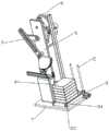
为解决上述技术问题,本发明采用如下技术方案:一种用于锂电池托盘的升降式梯次拆分装置,包括安装底板,安装底板的顶端一侧固定安装有导向机构,且导向机构上固定连接有输送机构,输送机构上可拆卸设有阵列分布的锂电池托盘本体,安装底板的顶端另一侧固定安装有Z型安装板,且Z型安装板的上端设有与输送机构配合使用的升降机构,Z型安装板上设有与升降机构以及锂电池托盘本体配合使用的拆分机构。In order to solve the above-mentioned technical problems, the present invention adopts the following technical solution: a lift-type step dismantling device for lithium battery trays, including a mounting base plate, a guiding mechanism is fixedly installed on the top side of the mounting base plate, and the guiding mechanism is fixedly connected to There is a conveying mechanism, and the lithium battery tray body distributed in an array is detachable on the conveying mechanism, and a Z-shaped mounting plate is fixedly installed on the other side of the top of the installation bottom plate, and the upper end of the Z-shaped mounting plate is provided with a lift for use with the conveying mechanism Mechanism, the Z-shaped mounting plate is equipped with a split mechanism that is used in conjunction with the lifting mechanism and the lithium battery tray body.
优选地,导向机构包括垂向导杆,垂向导杆设置有两个,且垂向导杆固定安装在安装底板上,垂向导杆上滑动套接有导向横板,且导向横板上贯穿开设有导向穿孔,导向穿孔的内壁上开设有阵列分布的第一卡孔,且第一卡孔内活动卡接有第一滚珠,垂向导杆滑动插设在导向穿孔内,且第一滚珠与垂向导杆的外壁活动接触,输送机构包括U型输送架,U型输送架与两个导向横板固定连接,且U型输送架靠近导向横板的一端转动插设有第一输送辊,U型输送架远离导向横板的一端转动插接有第二输送辊,且第二输送辊与第一输送辊的外侧传动套接有输送带,锂电池托盘本体能够与输送带滑动贴合,且U型输送架远离锂电池托盘本体的一端固定安装有第一支架,第一支架的内侧固定插接有第一伺服电机,且第一伺服电机输出端的末端与第一输送辊固定连接。Preferably, the guide mechanism includes a vertical guide rod. There are two vertical guide rods, and the vertical guide rods are fixedly installed on the installation base plate. Perforation, the inner wall of the guide perforation is provided with an array of first clamping holes, and the first clamping hole is movably clamped with the first ball, the vertical guide rod is slidably inserted in the guide perforation, and the first ball and the vertical guide rod The outer wall of the U-shaped conveyor is in movable contact, and the conveying mechanism includes a U-shaped conveying frame. The end away from the guide horizontal plate is rotated and inserted with the second conveyor roller, and the conveyor belt is sleeved on the outer drive of the second conveyor roller and the first conveyor roller. The lithium battery tray body can slide and fit with the conveyor belt, and the U-shaped conveyor The end of the rack away from the lithium battery tray body is fixedly installed with a first bracket, the inner side of the first bracket is fixedly plugged with a first servo motor, and the end of the output end of the first servo motor is fixedly connected with the first conveying roller.
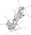
优选地,升降机构包括第二支架与第一转杆,第二支架固定安装在Z型安装板上,且第二支架的内侧固定插接有第二伺服电机,第二伺服电机输出端的末端固定连接有第二转杆,且第二转杆转动插设在Z型安装板上,第二转杆上固定套接有驱动凸轮,且驱动凸轮靠近第二伺服电机的一侧固定安装有配合使用的弧形限位板与驱动推杆,第一转杆转动插设在Z型安装板的上端,Z型安装板的上端贯穿开设有第一转孔与第二转孔,第一转杆转动插设在第一转孔内,且第二转杆转动插设在第二转孔内,且第一转杆上固定套接有Y型从动板,Y型从动板上开设有阵列分布的弧形限位槽与驱动凹槽,且弧形限位槽与驱动凹槽呈交错分布,弧形限位板的外壁能够与弧形限位槽的内壁相贴合,且驱动推杆能够活动插设在驱动凹槽内,第一转杆的末端固定套设有第一齿轮,且安装底板上滑动安装有第一齿条,安装底板上固定安装有导向滑杆,且第一齿条上贯穿开设有导向滑孔,导向滑杆滑动插设在导向滑孔内,第一齿条与第一齿轮相啮合,且第一齿条的下端固定安装有Z型连接杆,Z型连接杆与U型输送架固定连接。Preferably, the lifting mechanism includes a second bracket and a first rotating rod, the second bracket is fixedly installed on the Z-shaped mounting plate, and the inner side of the second bracket is fixedly plugged with a second servo motor, and the end of the output end of the second servo motor is fixed The second rotating rod is connected, and the second rotating rod is rotated and inserted on the Z-shaped mounting plate. The driving cam is fixedly sleeved on the second rotating rod, and the driving cam is fixedly installed on the side close to the second servo motor. The arc-shaped limit plate and the drive push rod, the first rotating rod is rotated and inserted on the upper end of the Z-shaped mounting plate, and the upper end of the Z-shaped mounting plate is provided with a first rotating hole and a second rotating hole, and the first rotating rod rotates Inserted in the first rotating hole, and the second rotating rod is rotated and inserted in the second rotating hole, and the first rotating rod is fixedly sleeved with a Y-shaped driven plate, and the Y-shaped driven plate is provided with an array distribution The arc-shaped limiting groove and the driving groove are distributed alternately, the outer wall of the arc-shaped limiting plate can fit the inner wall of the arc-shaped limiting groove, and the driving push rod can It is movably inserted in the drive groove, the end of the first rotating rod is fixedly sleeved with the first gear, and the first rack is slidably installed on the installation base, and the guide slide bar is fixedly installed on the installation base, and the first rack A guide slide hole is opened on the top, and the guide slide rod is slid and inserted in the guide slide hole. The first rack is meshed with the first gear, and the lower end of the first rack is fixedly installed with a Z-shaped connecting rod. The Z-shaped connecting rod It is fixedly connected with the U-shaped conveyor frame.
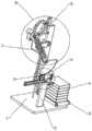
优选地,拆分机构包括推动转板与第三转杆,推动转板固定套设在第二转杆的末端,且推动转板远离第二转杆的一端转动安装有推动转柱,第三转杆转动插设在Z型安装板上,且第三转杆的末端转动套接有从动转板,从动转板上贯穿开设有推动穿槽,且推动转柱活动插设在推动穿槽内,从动转板的底端固定安装有半面齿轮,Z型安装板上转动插设有第四转杆,Z型安装板上贯穿开设有第三转孔与第四转孔,第三转杆转动插设在第三转孔内,且第四转杆转动插设在第四转孔内,且第四转杆上转动套设有第二齿轮,第二齿轮与半面齿轮相啮合,Z型安装板上滑动安装有第二齿条,Z型安装板上固定安装有导向滑轨,且导向滑轨上滑动套设有导向滑板,导向滑板与第二齿条固定连接,且第二齿条与第二齿轮相啮合,第二齿条的一端固定连接有横向推杆,且横向推杆的末端固定连接有固定导环,固定导环内滑动插设有垂向滑杆,且垂向滑杆的顶端固定套接有固定套环,固定套环的底端固定安装有复位弹簧,复位弹簧活动套设在垂向滑杆上,且复位弹簧的底端与固定导环固定连接,垂向滑杆的底端固定连接有拆分推板,且拆分推板能够与锂电池托盘本体相接触,拆分推板的底端开设有阵列分布的第二卡孔,且第二卡孔内活动卡接有与锂电池托盘本体配合使用的第二滚珠。Preferably, the disassembly mechanism includes a push rotating plate and a third rotating rod, the pushing rotating plate is fixedly sleeved at the end of the second rotating rod, and a pushing rotating column is installed on the end of the pushing rotating plate away from the second rotating rod, and the third The rotary rod is rotated and inserted on the Z-shaped mounting plate, and the end of the third rotary rod is rotated and sleeved with a driven rotary plate. In the groove, a half-face gear is fixedly installed on the bottom end of the driven rotating plate, a fourth rotating rod is inserted on the Z-shaped mounting plate, and a third rotating hole and a fourth rotating hole are opened on the Z-shaped mounting plate. The rotating rod is rotatably inserted in the third rotating hole, and the fourth rotating rod is rotatably inserted in the fourth rotating hole, and the fourth rotating rod is rotatably provided with a second gear, the second gear meshes with the half-face gear, A second rack is slidably installed on the Z-shaped mounting plate, and a guide rail is fixedly installed on the Z-shaped mounting plate, and a guide slide is provided on the slide sleeve on the guide slide, and the guide slide is fixedly connected with the second rack, and the second The rack is meshed with the second gear, one end of the second rack is fixedly connected with a horizontal push rod, and the end of the horizontal push rod is fixedly connected with a fixed guide ring, and a vertical slide bar is slid and inserted in the fixed guide ring. A fixed collar is fixedly sleeved to the top of the slide bar, and a return spring is fixedly installed at the bottom of the fixed collar, and the return spring is movably sleeved on the vertical slide bar, and the bottom end of the return spring is fixedly connected with the fixed guide ring, The bottom end of the vertical slide bar is fixedly connected with a detachable push plate, and the detachable push plate can be in contact with the lithium battery tray body. A second ball used in conjunction with the lithium battery tray body is movable in the hole.
与现有技术相比,本发明的有益效果在于:Compared with prior art, the beneficial effect of the present invention is:
1、通过升降机构的设置使用,能够通过第一转杆带动第一齿轮做一百二十度的间歇性转动,从而能够带动第一齿条做间歇性的上移运动,进而能够通过Z型连接杆带动输送机构做间歇性的上移运动,进一步能够带动待拆分的堆叠锂电池托盘本体做间歇性上移运动,从而便于将其进行梯次拆分,无需人工作业;1. Through the setting and use of the lifting mechanism, the first gear can be driven to do intermittent rotation of 120 degrees through the first rotating rod, so that the first rack can be driven to move up intermittently, and then can be passed through the Z-type The connecting rod drives the conveying mechanism to move up intermittently, which can further drive the stacked lithium battery tray body to be disassembled to move up intermittently, so that it can be disassembled step by step without manual work;
2、通过拆分机构的设置使用,能够带动第二齿轮做循环往复转动,从而能够带动第二齿条做循环往复移动,进而能够通过横向推杆、固定导环与垂向滑杆带动拆分推板做循环往复移动,进一步能够将最上层的锂电池托盘本体依次进行拆分移送,从而节省了人力,且提高了拆分效率与拆分可靠性;2. Through the setting and use of the split mechanism, it can drive the second gear to rotate reciprocatingly, thereby driving the second rack to move reciprocatingly, and then drive the split through the horizontal push rod, fixed guide ring and vertical slide bar The push plate moves back and forth in a cycle, which can further disassemble and transfer the uppermost lithium battery tray body in sequence, thus saving manpower and improving disassembly efficiency and reliability;
3、通过导向机构与输送机构的配合使用,能够将待拆分的堆叠锂电池托盘本体移至合适位置并能够保障其稳步上移,从而能够保障拆分作业的稳步开展。3. Through the combined use of the guide mechanism and the conveying mechanism, the stacked lithium battery tray body to be disassembled can be moved to a suitable position and can be guaranteed to move up steadily, thereby ensuring the steady development of the disassembly operation.
附图说明Description of drawings
为了更清楚地说明本发明实施例或现有技术中的技术方案,下面将对实施例或现有技术描述中所需要使用的附图作简单地介绍,显而易见地,下面描述中的附图仅仅是本发明的一些实施例,对于本领域普通技术人员来讲,在不付出创造性劳动的前提下,还可以根据这些附图获得其他的附图。In order to more clearly illustrate the technical solutions in the embodiments of the present invention or the prior art, the following will briefly introduce the drawings that need to be used in the description of the embodiments or the prior art. Obviously, the accompanying drawings in the following description are only These are some embodiments of the present invention. Those skilled in the art can also obtain other drawings based on these drawings without creative work.
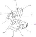
图1为本发明结构示意图;Fig. 1 is a structural representation of the present invention;
图2为本发明中拆分机构安装示意图;Fig. 2 is the schematic diagram of disassembling mechanism installation in the present invention;
图3为本发明图2中A处结构放大示意图;Fig. 3 is the enlarged schematic view of the structure at A place in Fig. 2 of the present invention;
图4为本发明图2中B处结构放大示意图;Fig. 4 is the enlarged schematic view of the structure at B place in Fig. 2 of the present invention;
图5为本发明中升降机构安装示意图;Fig. 5 is the installation schematic diagram of lifting mechanism in the present invention;
图6为本发明图5中C处结构放大示意图;Fig. 6 is the enlarged schematic view of the structure at C in Fig. 5 of the present invention;
图7为本发明图5中D处结构放大示意图;Fig. 7 is the enlarged schematic view of the structure at D in Fig. 5 of the present invention;
图8为本发明图5中E处结构放大示意图;Figure 8 is an enlarged schematic view of the structure at E in Figure 5 of the present invention;
图9为本发明中升降机构连接示意图。Fig. 9 is a schematic diagram of connection of the lifting mechanism in the present invention.
图中:1、安装底板;2、导向机构;21、垂向导杆;22、导向横板;23、导向穿孔;24、第一卡孔;25、第一滚珠;3、输送机构;31、U型输送架;32、第一输送辊;33、第二输送辊;34、输送带;35、第一支架;36、第一伺服电机;4、锂电池托盘本体;5、Z型安装板;51、第一转孔;52、第二转孔;53、第三转孔;54、第四转孔;6、升降机构;61、第二支架;62、第一转杆;63、第二伺服电机;64、第二转杆;65、驱动凸轮;66、弧形限位板;67、驱动推杆;68、Y型从动板;69、弧形限位槽;610、驱动凹槽;611、第一齿轮;612、第一齿条;613、Z型连接杆;614、导向滑杆;615、导向滑孔;7、拆分机构;71、推动转板;72、第三转杆;73、推动转柱;74、从动转板;75、推动穿槽;76、半面齿轮;77、第四转杆;78、第二齿轮;79、第二齿条;710、横向推杆;711、固定导环;712、垂向滑杆;713、固定套环;714、复位弹簧;715、拆分推板;716、导向滑轨;717、导向滑板;718、第二卡孔;719、第二滚珠。In the figure: 1. Base plate installation; 2. Guide mechanism; 21. Vertical guide rod; 22. Guide horizontal plate; 23. Guide perforation; 24. First card hole; 25. First ball; 3. Conveying mechanism; U-shaped conveyor frame; 32. First conveyor roller; 33. Second conveyor roller; 34. Conveyor belt; 35. First bracket; 36. First servo motor; 4. Lithium battery tray body; 5. Z-shaped mounting plate ;51, the first rotating hole; 52, the second rotating hole; 53, the third rotating hole; 54, the fourth rotating hole; 6, the lifting mechanism; 61, the second bracket; 62, the first rotating rod; 63, the first Two servo motors; 64, the second rotating rod; 65, driving cam; 66, arc-shaped limiting plate; 67, driving push rod; 68, Y-shaped driven plate; 69, arc-shaped limiting groove; 610, driving concave Groove; 611, the first gear; 612, the first rack; 613, Z-shaped connecting rod; 614, guide slide bar; 615, guide slide hole; 7, split mechanism; Rotary rod; 73, promote rotating column; 74, driven rotating plate; 75, push through slot; 76, half-face gear; 77, fourth rotating rod; 78, second gear; 79, second rack; Push rod; 711, fixed guide ring; 712, vertical slide bar; 713, fixed collar; 714, return spring; 715, split push plate; 716, guide slide rail; 717, guide slide plate; 718, second card Hole; 719, the second ball.
具体实施方式Detailed ways
下面将结合本发明实施例中的附图,对本发明实施例中的技术方案进行清楚、完整地描述,显然,所描述的实施例仅仅是本发明一部分实施例,而不是全部的实施例。基于本发明中的实施例,本领域普通技术人员在没有做出创造性劳动前提下所获得的所有其他实施例,都属于本发明保护的范围。The following will clearly and completely describe the technical solutions in the embodiments of the present invention with reference to the accompanying drawings in the embodiments of the present invention. Obviously, the described embodiments are only some, not all, embodiments of the present invention. Based on the embodiments of the present invention, all other embodiments obtained by persons of ordinary skill in the art without making creative efforts belong to the protection scope of the present invention.
实施例:如图1-9所示,本发明提供了一种用于锂电池托盘的升降式梯次拆分装置,包括安装底板1,安装底板1的顶端一侧固定安装有导向机构2,且导向机构2上固定连接有输送机构3,输送机构3上可拆卸设有阵列分布的锂电池托盘本体4,安装底板1的顶端另一侧固定安装有Z型安装板5,且Z型安装板5的上端设有与输送机构3配合使用的升降机构6,Z型安装板5上设有与升降机构6以及锂电池托盘本体4配合使用的拆分机构7,安装底板1上设有与输送机构3配合使用的导料机构与传料机构,从而能够将待拆分的堆叠锂电池托盘本体4导至输送机构3上并将拆分后的锂电池托盘本体4逐个移送走,此为现有技术,此处不做过多赘述。Embodiment: As shown in Figures 1-9, the present invention provides a lift-type step-by-step disassembly device for lithium battery trays, including a mounting base plate 1, a guide mechanism 2 is fixedly installed on the top side of the mounting base plate 1, and The guide mechanism 2 is fixedly connected with the conveying
导向机构2包括垂向导杆21,垂向导杆21设置有两个,且垂向导杆21固定安装在安装底板1上,垂向导杆21上滑动套接有导向横板22,且导向横板22上贯穿开设有导向穿孔23,导向穿孔23的内壁上开设有阵列分布的第一卡孔24,且第一卡孔24内活动卡接有第一滚珠25,垂向导杆21滑动插设在导向穿孔23内,且第一滚珠25与垂向导杆21的外壁活动接触,第一滚珠25的设置使用为导向横板22的滑动调节提供了便利,且通过垂向导杆21、导向横板22与第一滚珠25的配合使用,对U型输送架31的稳定移送提供了保障,输送机构3包括U型输送架31,U型输送架31与两个导向横板22固定连接,且U型输送架31靠近导向横板22的一端转动插设有第一输送辊32,U型输送架31远离导向横板22的一端转动插接有第二输送辊33,且第二输送辊33与第一输送辊32的外侧传动套接有输送带34,锂电池托盘本体4能够与输送带34滑动贴合,且U型输送架31远离锂电池托盘本体4的一端固定安装有第一支架35,第一支架35的内侧固定插接有第一伺服电机36,且第一伺服电机36输出端的末端与第一输送辊32固定连接。The guide mechanism 2 includes a
通过采用上述技术方案,使用时,使用者可将导料机构与第一伺服电机36打开,从而能够将待拆分的堆叠锂电池托盘本体4逐步向输送机构3移送,与此同时,第一伺服电机36将带动第一输送辊32转动,从而能够配合第二输送辊33的使用带动输送带34转动,进而能够在堆叠锂电池托盘本体4从导料机构移至输送带34上时将其继续移送,直至将堆叠的锂电池托盘本体4移至合适位置时关闭导料机构与第一伺服电机36。By adopting the above technical solution, when in use, the user can open the material guide mechanism and the
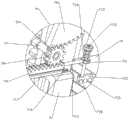
升降机构6包括第二支架61与第一转杆62,第二支架61固定安装在Z型安装板5上,且第二支架61的内侧固定插接有第二伺服电机63,第二伺服电机63输出端的末端固定连接有第二转杆64,且第二转杆64转动插设在Z型安装板5上,第二转杆64上固定套接有驱动凸轮65,且驱动凸轮65靠近第二伺服电机63的一侧固定安装有配合使用的弧形限位板66与驱动推杆67,第一转杆62转动插设在Z型安装板5的上端,Z型安装板5的上端贯穿开设有第一转孔51与第二转孔52,第一转杆62转动插设在第一转孔51内,且第二转杆64转动插设在第二转孔52内,第一转孔51与第二转孔52的设置使用为第一转杆62与第二转杆64的稳定转动提供了保障,且第一转杆62上固定套接有Y型从动板68,Y型从动板68上开设有阵列分布的弧形限位槽69与驱动凹槽610,且弧形限位槽69与驱动凹槽610呈交错分布,弧形限位板66的外壁能够与弧形限位槽69的内壁相贴合,且驱动推杆67能够活动插设在驱动凹槽610内,第一转杆62的末端固定套设有第一齿轮611,且安装底板1上滑动安装有第一齿条612,安装底板1上固定安装有导向滑杆614,且第一齿条612上贯穿开设有导向滑孔615,导向滑杆614滑动插设在导向滑孔615内,通过导向滑杆614与导向滑孔615的配合使用,对第一齿条612的移动调节起到了限位及导向作用,第一齿条612与第一齿轮611相啮合,且第一齿条612的下端固定安装有Z型连接杆613,Z型连接杆613与U型输送架31固定连接。The
通过采用上述技术方案,使用时,驱动凸轮65将带动弧形限位板66与驱动推杆67转动,当弧形限位板66与对应弧形限位槽69分离时,驱动推杆67将卡入对应驱动凹槽610内,随后驱动推杆67将沿着对应驱动凹槽610的内壁做一次往复滑动,且当驱动推杆67与对应驱动凹槽610分离时,弧形限位板66将卡入下一弧形限位槽69内,之后将重复上述步骤,从而能够带动Y型从动板68做一百二十度的间歇性转动,进而能够通过第一转杆62带动第一齿轮611做一百二十度的间歇性转动,进一步能够带动第一齿条612做间歇性的上移运动,从而能够通过Z型连接杆613带动输送机构3做间歇性的上移运动,进一步能够带动待拆分的堆叠锂电池托盘本体4做间歇性上移。By adopting the above-mentioned technical scheme, during use, the driving
拆分机构7包括推动转板71与第三转杆72,推动转板71固定套设在第二转杆64的末端,且推动转板71远离第二转杆64的一端转动安装有推动转柱73,第三转杆72转动插设在Z型安装板5上,且第三转杆72的末端转动套接有从动转板74,从动转板74上贯穿开设有推动穿槽75,且推动转柱73活动插设在推动穿槽75内,从动转板74的底端固定安装有半面齿轮76,Z型安装板5上转动插设有第四转杆77,Z型安装板5上贯穿开设有第三转孔53与第四转孔54,第三转杆72转动插设在第三转孔53内,且第四转杆77转动插设在第四转孔54内,第三转孔53与第四转孔54的配合使用,对第三转杆72与第四转杆77的稳定转动提供了保障,且第四转杆77上转动套设有第二齿轮78,第二齿轮78与半面齿轮76相啮合,Z型安装板5上滑动安装有第二齿条79,Z型安装板5上固定安装有导向滑轨716,且导向滑轨716上滑动套设有导向滑板717,导向滑板717与第二齿条79固定连接,通过导向滑轨716与导向滑板717的配合使用,对第二齿条79的移动调节起到了限位及导向作用,且第二齿条79与第二齿轮78相啮合,第二齿条79的一端固定连接有横向推杆710,且横向推杆710的末端固定连接有固定导环711,固定导环711内滑动插设有垂向滑杆712,且垂向滑杆712的顶端固定套接有固定套环713,固定套环713的底端固定安装有复位弹簧714,复位弹簧714活动套设在垂向滑杆712上,且复位弹簧714的底端与固定导环711固定连接,垂向滑杆712的底端固定连接有拆分推板715,且拆分推板715能够与锂电池托盘本体4相接触,拆分推板715的底端开设有阵列分布的第二卡孔718,且第二卡孔718内活动卡接有与锂电池托盘本体4配合使用的第二滚珠719,第二滚珠719的设置使用为拆分推板715与锂电池托盘本体4的相对滑动提供了便利。The
通过采用上述技术方案,使用时,推动转板71能够带动推动转柱73转动,进一步能够使推动转柱73沿着推动穿槽75的内壁进行循环滚动,从而能够使从动转板74沿着第三转杆72做循环往复摆动,进而能够带动半面齿轮76做循环往复摆动,进一步能够配合第四转杆77的使用带动第二齿轮78做循环往复转动,从而能够带动第二齿条79做循环往复移动,且在第二齿条79初始移动时将通过横向推杆710带动固定导环711向远离导向滑轨716的一侧移动,从而能够带动固定导环711以及垂向滑杆712向远离导向滑轨716的一侧移动,进而能够带动拆分推板715向远离导向滑轨716的一侧移动并将最上层的锂电池托盘本体4推至传料机构上进行移送。By adopting the above-mentioned technical scheme, when in use, the pushing rotating
工作原理:使用时,使用者可将导料机构与第一伺服电机36打开,从而能够将待拆分的堆叠锂电池托盘本体4逐步向输送机构3移送,与此同时,第一伺服电机36将带动第一输送辊32转动,从而能够配合第二输送辊33的使用带动输送带34转动,进而能够在堆叠锂电池托盘本体4从导料机构移至输送带34上时将其继续移送,直至将堆叠的锂电池托盘本体4移至合适位置时关闭导料机构与第一伺服电机36;Working principle: When in use, the user can open the material guide mechanism and the
随后可将传料机构与第二伺服电机63打开,此时第二伺服电机63将带动第二转杆64转动,从而能够带动驱动凸轮65与推动转板71转动,进而能够带动推动转柱73转动,进一步能够使推动转柱73沿着推动穿槽75的内壁进行循环滚动,从而能够使从动转板74沿着第三转杆72做循环往复摆动,进而能够带动半面齿轮76做循环往复摆动,进一步能够配合第四转杆77的使用带动第二齿轮78做循环往复转动,从而能够带动第二齿条79做循环往复移动,且在第二齿条79初始移动时将通过横向推杆710带动固定导环711向远离导向滑轨716的一侧移动,从而能够带动固定导环711以及垂向滑杆712向远离导向滑轨716的一侧移动,进而能够带动拆分推板715向远离导向滑轨716的一侧移动并将最上层的锂电池托盘本体4推至传料机构上进行移送;Then the material transfer mechanism and the
与此同时,驱动凸轮65将带动弧形限位板66与驱动推杆67转动,当弧形限位板66与对应弧形限位槽69分离时,驱动推杆67将卡入对应驱动凹槽610内,随后驱动推杆67将沿着对应驱动凹槽610的内壁做一次往复滑动,且当驱动推杆67与对应驱动凹槽610分离时,弧形限位板66将卡入下一弧形限位槽69内,之后将重复上述步骤,从而能够带动Y型从动板68做一百二十度的间歇性转动,进而能够通过第一转杆62带动第一齿轮611做一百二十度的间歇性转动,进一步能够带动第一齿条612做间歇性的上移运动,从而能够通过Z型连接杆613带动输送机构3做间歇性的上移运动,进一步能够带动待拆分的堆叠锂电池托盘本体4做间歇性上移,在此期间,当待拆分堆叠锂电池托盘本体4开始上移时最上层的锂电池托盘本体4已完成拆分并进行移送,且此时拆分推板715将进行复位,而当待拆分堆叠锂电池托盘本体4的最上端与第二滚珠719相接触时能够推动拆分推板715上移,且此时第二滚珠719将沿着待拆分堆叠锂电池托盘本体4的最上端滚动,从而能够通过固定套环713拉伸复位弹簧714,当拆分推板715复位后,此时拆分推板715将与待拆分的堆叠锂电池托盘本体4完全分离,且此时复位弹簧714将带动拆分推板715下移并复位,之后将重复上述步骤,从而能够堆叠的锂电池托盘本体4逐步拆分并进行移送,之后可将输送机构3等复位并重复上述步骤进行后续待拆分堆叠锂电池托盘本体4的拆分作业。At the same time, the driving
显然,本领域的技术人员可以对本发明进行各种改动和变型而不脱离本发明的精神和范围。这样,倘若本发明的这些修改和变型属于本发明权利要求及其等同技术的范围之内,则本发明也意图包含这些改动和变型在内。Obviously, those skilled in the art can make various changes and modifications to the present invention without departing from the spirit and scope of the present invention. Thus, if these modifications and variations of the present invention fall within the scope of the claims of the present invention and their equivalent technologies, the present invention also intends to include these modifications and variations.
Claims (10)
Translated fromChinesePriority Applications (1)
| Application Number | Priority Date | Filing Date | Title |
|---|---|---|---|
| CN202310263197.7ACN116101794A (en) | 2023-03-17 | 2023-03-17 | A lift-type step-by-step splitting device for lithium battery trays |
Applications Claiming Priority (1)
| Application Number | Priority Date | Filing Date | Title |
|---|---|---|---|
| CN202310263197.7ACN116101794A (en) | 2023-03-17 | 2023-03-17 | A lift-type step-by-step splitting device for lithium battery trays |
Publications (1)
| Publication Number | Publication Date |
|---|---|
| CN116101794Atrue CN116101794A (en) | 2023-05-12 |
Family
ID=86267438
Family Applications (1)
| Application Number | Title | Priority Date | Filing Date |
|---|---|---|---|
| CN202310263197.7APendingCN116101794A (en) | 2023-03-17 | 2023-03-17 | A lift-type step-by-step splitting device for lithium battery trays |
Country Status (1)
| Country | Link |
|---|---|
| CN (1) | CN116101794A (en) |
Cited By (3)
| Publication number | Priority date | Publication date | Assignee | Title |
|---|---|---|---|---|
| CN117022780A (en)* | 2023-10-09 | 2023-11-10 | 南通实创电子科技有限公司 | Packaging machine for new energy battery production |
| CN118373219A (en)* | 2024-06-21 | 2024-07-23 | 珠海市申科谱工业科技有限公司 | Tray feeding and discharging trolley |
| CN120573397A (en)* | 2025-08-05 | 2025-09-02 | 内蒙古自治区烟草公司通辽市公司 | Auxiliary lifting carrying frame device for cigarette warehouse-in |
Citations (6)
| Publication number | Priority date | Publication date | Assignee | Title |
|---|---|---|---|---|
| CN205151211U (en)* | 2015-10-23 | 2016-04-13 | 江苏拓新天机器人科技有限公司 | Lithium battery tray separator |
| CN110733876A (en)* | 2019-10-16 | 2020-01-31 | 浙江圣奥家具制造有限公司 | furniture board production line loading attachment |
| CN213230383U (en)* | 2020-07-23 | 2021-05-18 | 菏泽盘德信息技术有限公司 | Material conveying device for composite board production |
| CN114420612A (en)* | 2022-01-21 | 2022-04-29 | 张祥 | Thick film hybrid integrated circuit multi-module pin insertion machine |
| CN114950216A (en)* | 2022-04-07 | 2022-08-30 | 安徽高芯众科半导体有限公司 | Preparation equipment of oxidation nail dispersion liquid applied to ceramic coating |
| CN115608813A (en)* | 2022-10-19 | 2023-01-17 | 南通晋弘钢结构工程有限公司 | Steel construction processing orthotic devices |
- 2023
- 2023-03-17CNCN202310263197.7Apatent/CN116101794A/enactivePending
Patent Citations (6)
| Publication number | Priority date | Publication date | Assignee | Title |
|---|---|---|---|---|
| CN205151211U (en)* | 2015-10-23 | 2016-04-13 | 江苏拓新天机器人科技有限公司 | Lithium battery tray separator |
| CN110733876A (en)* | 2019-10-16 | 2020-01-31 | 浙江圣奥家具制造有限公司 | furniture board production line loading attachment |
| CN213230383U (en)* | 2020-07-23 | 2021-05-18 | 菏泽盘德信息技术有限公司 | Material conveying device for composite board production |
| CN114420612A (en)* | 2022-01-21 | 2022-04-29 | 张祥 | Thick film hybrid integrated circuit multi-module pin insertion machine |
| CN114950216A (en)* | 2022-04-07 | 2022-08-30 | 安徽高芯众科半导体有限公司 | Preparation equipment of oxidation nail dispersion liquid applied to ceramic coating |
| CN115608813A (en)* | 2022-10-19 | 2023-01-17 | 南通晋弘钢结构工程有限公司 | Steel construction processing orthotic devices |
Cited By (4)
| Publication number | Priority date | Publication date | Assignee | Title |
|---|---|---|---|---|
| CN117022780A (en)* | 2023-10-09 | 2023-11-10 | 南通实创电子科技有限公司 | Packaging machine for new energy battery production |
| CN117022780B (en)* | 2023-10-09 | 2023-12-26 | 南通实创电子科技有限公司 | Packaging machine for new energy battery production |
| CN118373219A (en)* | 2024-06-21 | 2024-07-23 | 珠海市申科谱工业科技有限公司 | Tray feeding and discharging trolley |
| CN120573397A (en)* | 2025-08-05 | 2025-09-02 | 内蒙古自治区烟草公司通辽市公司 | Auxiliary lifting carrying frame device for cigarette warehouse-in |
Similar Documents
| Publication | Publication Date | Title |
|---|---|---|
| CN116101794A (en) | A lift-type step-by-step splitting device for lithium battery trays | |
| WO2023236599A1 (en) | Tea leaf rolling processing apparatus for tea pretreatment, and processing method thereof | |
| CN209889777U (en) | Material tray conveying device and feeding device | |
| CN110202965B (en) | Stamping tool for accountants | |
| CN206500844U (en) | Accurate haulage gear for driving pallet | |
| CN103050717A (en) | Automatic ring buckling device for cathodes of button cells | |
| CN105034625B (en) | A kind of automatic stamping machine and its method of work | |
| CN219657703U (en) | Lithium battery detection device | |
| CN206838813U (en) | Gantry rotation formula web-like Plate Bending Machine | |
| CN206322781U (en) | Liquid injection device for soft pack lithium battery | |
| CN105109927B (en) | Automatic transfer machine structure for cylindrical work | |
| CN107261956A (en) | A kind of automated processing equipment of food processing field | |
| CN209448329U (en) | A kind of lateral cable trench cover automatic laying device | |
| CN216824901U (en) | A extraction cauldron for preparing 2, 6-dihydroxy benxolic acid | |
| CN217850544U (en) | Poria cocos strain inoculating machine | |
| CN217560985U (en) | Lithium battery pole piece scraping and sampling device | |
| CN206720290U (en) | A kind of cell safety feeding device | |
| CN208943984U (en) | A kind of medical manufacture test tube oscillating uniform device | |
| CN108970506A (en) | A high-efficiency mixing and stirring device for architectural coatings | |
| CN115305798A (en) | A marking device for shipyard site division | |
| CN113134483A (en) | Dust brushing equipment for production and processing of lithium battery pole pieces | |
| CN110812065A (en) | an automatic dispensing machine | |
| CN213382321U (en) | Forming equipment is used in production of hollow net weight of pottery | |
| CN216125985U (en) | Automatic glue dispenser for miniature transformer | |
| CN118362360B (en) | Sampling device for lake water quality detection |
Legal Events
| Date | Code | Title | Description |
|---|---|---|---|
| PB01 | Publication | ||
| PB01 | Publication | ||
| SE01 | Entry into force of request for substantive examination | ||
| SE01 | Entry into force of request for substantive examination |