CN116096481A - Spiral Wound Membrane Module with Sensor and Emitter - Google Patents
Spiral Wound Membrane Module with Sensor and EmitterDownload PDFInfo
- Publication number
- CN116096481A CN116096481ACN202180061639.9ACN202180061639ACN116096481ACN 116096481 ACN116096481 ACN 116096481ACN 202180061639 ACN202180061639 ACN 202180061639ACN 116096481 ACN116096481 ACN 116096481A
- Authority
- CN
- China
- Prior art keywords
- end cap
- spiral wound
- cap assembly
- wound module
- feed
- Prior art date
- Legal status (The legal status is an assumption and is not a legal conclusion. Google has not performed a legal analysis and makes no representation as to the accuracy of the status listed.)
- Pending
Links
Images


Classifications
- B—PERFORMING OPERATIONS; TRANSPORTING
- B01—PHYSICAL OR CHEMICAL PROCESSES OR APPARATUS IN GENERAL
- B01D—SEPARATION
- B01D63/00—Apparatus in general for separation processes using semi-permeable membranes
- B01D63/10—Spiral-wound membrane modules
- B—PERFORMING OPERATIONS; TRANSPORTING
- B01—PHYSICAL OR CHEMICAL PROCESSES OR APPARATUS IN GENERAL
- B01D—SEPARATION
- B01D61/00—Processes of separation using semi-permeable membranes, e.g. dialysis, osmosis or ultrafiltration; Apparatus, accessories or auxiliary operations specially adapted therefor
- B01D61/02—Reverse osmosis; Hyperfiltration ; Nanofiltration
- B01D61/10—Accessories; Auxiliary operations
- B—PERFORMING OPERATIONS; TRANSPORTING
- B01—PHYSICAL OR CHEMICAL PROCESSES OR APPARATUS IN GENERAL
- B01D—SEPARATION
- B01D61/00—Processes of separation using semi-permeable membranes, e.g. dialysis, osmosis or ultrafiltration; Apparatus, accessories or auxiliary operations specially adapted therefor
- B01D61/02—Reverse osmosis; Hyperfiltration ; Nanofiltration
- B01D61/12—Controlling or regulating
- B—PERFORMING OPERATIONS; TRANSPORTING
- B01—PHYSICAL OR CHEMICAL PROCESSES OR APPARATUS IN GENERAL
- B01D—SEPARATION
- B01D61/00—Processes of separation using semi-permeable membranes, e.g. dialysis, osmosis or ultrafiltration; Apparatus, accessories or auxiliary operations specially adapted therefor
- B01D61/14—Ultrafiltration; Microfiltration
- B01D61/20—Accessories; Auxiliary operations
- B—PERFORMING OPERATIONS; TRANSPORTING
- B01—PHYSICAL OR CHEMICAL PROCESSES OR APPARATUS IN GENERAL
- B01D—SEPARATION
- B01D61/00—Processes of separation using semi-permeable membranes, e.g. dialysis, osmosis or ultrafiltration; Apparatus, accessories or auxiliary operations specially adapted therefor
- B01D61/14—Ultrafiltration; Microfiltration
- B01D61/22—Controlling or regulating
- B—PERFORMING OPERATIONS; TRANSPORTING
- B01—PHYSICAL OR CHEMICAL PROCESSES OR APPARATUS IN GENERAL
- B01D—SEPARATION
- B01D63/00—Apparatus in general for separation processes using semi-permeable membranes
- B01D63/10—Spiral-wound membrane modules
- B01D63/12—Spiral-wound membrane modules comprising multiple spiral-wound assemblies
- B—PERFORMING OPERATIONS; TRANSPORTING
- B01—PHYSICAL OR CHEMICAL PROCESSES OR APPARATUS IN GENERAL
- B01D—SEPARATION
- B01D65/00—Accessories or auxiliary operations, in general, for separation processes or apparatus using semi-permeable membranes
- B01D65/08—Prevention of membrane fouling or of concentration polarisation
- G—PHYSICS
- G01—MEASURING; TESTING
- G01L—MEASURING FORCE, STRESS, TORQUE, WORK, MECHANICAL POWER, MECHANICAL EFFICIENCY, OR FLUID PRESSURE
- G01L13/00—Devices or apparatus for measuring differences of two or more fluid pressure values
- G01L13/02—Devices or apparatus for measuring differences of two or more fluid pressure values using elastically-deformable members or pistons as sensing elements
- G01L13/025—Devices or apparatus for measuring differences of two or more fluid pressure values using elastically-deformable members or pistons as sensing elements using diaphragms
- G—PHYSICS
- G01—MEASURING; TESTING
- G01L—MEASURING FORCE, STRESS, TORQUE, WORK, MECHANICAL POWER, MECHANICAL EFFICIENCY, OR FLUID PRESSURE
- G01L19/00—Details of, or accessories for, apparatus for measuring steady or quasi-steady pressure of a fluent medium insofar as such details or accessories are not special to particular types of pressure gauges
- G01L19/0007—Fluidic connecting means
- B—PERFORMING OPERATIONS; TRANSPORTING
- B01—PHYSICAL OR CHEMICAL PROCESSES OR APPARATUS IN GENERAL
- B01D—SEPARATION
- B01D2313/00—Details relating to membrane modules or apparatus
- B01D2313/60—Specific sensors or sensor arrangements
- B—PERFORMING OPERATIONS; TRANSPORTING
- B01—PHYSICAL OR CHEMICAL PROCESSES OR APPARATUS IN GENERAL
- B01D—SEPARATION
- B01D2313/00—Details relating to membrane modules or apparatus
- B01D2313/70—Control means using a programmable logic controller [PLC] or a computer
- B01D2313/702—Control means using a programmable logic controller [PLC] or a computer comprising telecommunication features, e.g. modems or antennas
- B—PERFORMING OPERATIONS; TRANSPORTING
- B01—PHYSICAL OR CHEMICAL PROCESSES OR APPARATUS IN GENERAL
- B01D—SEPARATION
- B01D2313/00—Details relating to membrane modules or apparatus
- B01D2313/90—Additional auxiliary systems integrated with the module or apparatus
- B01D2313/903—Integrated control or detection device
- B—PERFORMING OPERATIONS; TRANSPORTING
- B01—PHYSICAL OR CHEMICAL PROCESSES OR APPARATUS IN GENERAL
- B01D—SEPARATION
- B01D2319/00—Membrane assemblies within one housing
- B01D2319/02—Elements in series
Landscapes
- Chemical & Material Sciences (AREA)
- Engineering & Computer Science (AREA)
- Water Supply & Treatment (AREA)
- Chemical Kinetics & Catalysis (AREA)
- Nanotechnology (AREA)
- Physics & Mathematics (AREA)
- General Physics & Mathematics (AREA)
- Separation Using Semi-Permeable Membranes (AREA)
Abstract
Description
Translated fromChinese技术领域technical field
本发明总体上涉及具有传感器和发射器的螺旋卷式膜模块,以及可用于流体中成分的分离或浓缩的相关组件。The present invention generally relates to spiral-wound membrane modules having sensors and emitters, and related assemblies useful for the separation or concentration of components in fluids.
背景技术Background technique
螺旋卷式膜模块用于若干流体分离应用中,包括反渗透、纳滤、超滤和微滤。在典型的工业实践中,螺旋卷式膜模块(“元件”)串联地连接在共用的压力容器内。设施通常包括多连串和/或多级容器,每个容器包括4至8个螺旋卷式膜模块。特别是对于高渗透性膜,比如微滤和超滤,在整个容器中维持均匀的通量分布可能是个问题。在模块内和沿容器向下的模块之间,进料侧和渗透物侧上的压力均在轴向和径向两个方向上变化。净驱动压力的差异会改变通量,进而影响分离性能、结垢、以及随后清洁模块的能力。在一些情况下,对于进料或渗透流体的水质测量(例如电导率、浑浊度、荧光反应)可以指示膜的泄露、变脏、结垢、或改变。在其他情形下,进料侧或渗透侧流体的变化的流量可以指示异常行为,和/或可以使用测得的值来针对这些操作条件将渗透物品质归一化。Spiral wound membrane modules are used in several fluid separation applications including reverse osmosis, nanofiltration, ultrafiltration and microfiltration. In typical industrial practice, spiral wound membrane modules ("elements") are connected in series within a common pressure vessel. Facilities typically include multiple series and/or multi-stage vessels, each vessel comprising 4 to 8 spiral wound membrane modules. Especially for highly permeable membranes, such as microfiltration and ultrafiltration, maintaining a uniform flux distribution throughout the vessel can be problematic. The pressure on both the feed side and the permeate side varies in both axial and radial directions, both within a module and between modules down the vessel. Differences in net driving pressure alter flux, which in turn affects separation performance, fouling, and subsequent ability to clean the module. In some cases, water quality measurements (eg, conductivity, turbidity, fluorescence response) on the feed or permeate fluid may indicate leaking, fouling, fouling, or alteration of the membrane. In other cases, varying flow rates of feed-side or permeate-side fluids may indicate abnormal behavior, and/or measured values may be used to normalize permeate quality to these operating conditions.
监测组件中的各个点处的压力、流量、电导率、浑浊度和/或荧光反应可以提供允许操作者采取适当措施(例如,选择性地更换模块、增加对进料流体的预处理、更积极地清洁模块)的信息。然而,由于模块被密封在压力容器内,监测进料流体和渗透流体、不同点处的流量、绝对压力、以及压力损失是困难的。然而,已经开发了各种技术,参见例如:US2014/0180610、US 8808539、US 8617397、US 8568596、US 8519559、US 8272251、US8210042、US 7886582、US 2011/10114561、WO 2012/117669以及JP 2016/019932。也已经对其他类型的过滤装置使用类似技术,例如,US 6936160、US 7048775和US 8221522。期望不太复杂的监测系统,包括提供以下一项或多项的那些监测系统:i)提高的准确性、ii)极少修改现有的模块和压力容器、iii)使用更少或更简单的传感器、以及iv)避开可缩回的探针。Monitoring pressure, flow, conductivity, turbidity, and/or fluorescent responses at various points in the assembly can provide information that allows the operator to take appropriate action (e.g., selectively replace modules, increase pre-treatment of feed fluids, more aggressive ground cleaning module) information. However, monitoring feed and permeate fluids, flow at various points, absolute pressure, and pressure loss is difficult because the module is sealed within a pressure vessel. However, various techniques have been developed, see for example: US2014/0180610, US 8808539, US 8617397, US 8568596, US 8519559, US 8272251, US8210042, US 7886582, US 2011/10114561, WO 2012/11766 9 and JP 2016/019932 . Similar techniques have also been used for other types of filtration devices, eg US 6936160, US 7048775 and US 8221522. Less complex monitoring systems are desired, including those that provide one or more of: i) increased accuracy, ii) minimal modifications to existing modules and pressure vessels, iii) use fewer or simpler The sensor, and iv) avoid the retractable probe.
发明内容Contents of the invention
本发明包括螺旋卷式膜模块和包括压力容器的相关组件、它们的制造和使用方法、以及此类组件的组合。螺旋卷式膜模块优选地包括围绕渗透物收集管卷绕的至少一个包膜。The present invention includes spiral wound membrane modules and related assemblies including pressure vessels, methods of their manufacture and use, and combinations of such assemblies. The spiral wound membrane module preferably comprises at least one envelope wound around a permeate collection tube.
本发明涉及一种螺旋卷式模块(2),其包括:The invention relates to a spiral wound module (2) comprising:
a)至少一个包膜(4),所述至少一个包膜围绕中空渗透物收集管(8)卷绕以形成具有第一卷面(30)、相反卷面(32)、以及外周边表面(3)的圆筒;a) At least one envelope (4) wrapped around a hollow permeate collection tube (8) to form a first wrap (30), an opposite wrap (32), and an outer peripheral surface ( 3) cylinder;
b)所述渗透物收集管(8)的多孔中心段(15),所述多孔中心段在轴向上位于所述渗透物收集管(8)的、靠近所述第一卷面(30)的第一远侧段(25)与所述渗透物收集管(8)的、靠近所述相反卷面(32)的相反远侧段(23)之间,其中,所述多孔中心段(15)包含孔洞(24),所述孔洞从所述渗透物收集管(8)的内表面(5)延伸至外表面(7)、并且将所述包膜(4)内的渗透物通道(12)连接至所述中空渗透物收集管(8)的内部空腔(9);b) the porous central section (15) of the permeate collection pipe (8), which is located axially on the permeate collection pipe (8) close to the first volume (30) Between the first distal section (25) of the permeate collection tube (8) and the opposite distal section (23) close to the opposite rolling surface (32), wherein the porous central section (15 ) contains holes (24) that extend from the inner surface (5) to the outer surface (7) of the permeate collection tube (8) and connect the permeate channels (12) in the envelope (4) ) connected to the inner cavity (9) of said hollow permeate collection pipe (8);
c)邻近于所述包膜(4)的进料通道(6),其中,所述进料通道适合使进料在所述第一卷面(30)与所述相反卷面(32)之间流经所述螺旋卷式膜模块(2),以及c) a feed channel (6) adjacent to said envelope (4), wherein said feed channel is adapted to feed material between said first lap (30) and said opposite lap (32) between flows through the spiral wound membrane module (2), and
d)至少一个端盖组件(31),所述至少一个端盖组件附连至所述螺旋卷式模块(2)并且邻近于所述第一卷面(30);d) at least one end cap assembly (31 ) attached to said spiral wound module (2) and adjacent to said first coil (30);
其中,所述螺旋卷式模块组件的特征在于:Wherein, the spiral wound module assembly is characterized in that:
所述端盖组件(31)包括微处理器、天线、LoRa发射器、以及连接至所述微处理器的至少一个传感器,其中,所述传感器适合测量对应于压力、压差、流量、电导率、声强度或光强度的值,并且其中,所述LoRa发射器适合通过以400MHz至1000MHz之间的射频提供顺序线性调频信号来发射所述测得的值。The end cap assembly (31) includes a microprocessor, an antenna, a LoRa transmitter, and at least one sensor connected to the microprocessor, wherein the sensor is suitable for measuring the corresponding pressure, differential pressure, flow rate, conductivity , a value of sound intensity or light intensity, and wherein said LoRa transmitter is adapted to transmit said measured value by providing a sequential chirp signal at a radio frequency between 400 MHz and 1000 MHz.
本发明进一步涉及一种螺旋卷式模块组件(21),其包括:The invention further relates to a spiral wound modular assembly (21) comprising:
a)压力容器(40),所述压力容器包括:腔室(41),所述腔室包括沿着轴线(X)在第一容器端(38)与第二容器端(38')之间延伸的内周边表面(60),以及至少一个进料入口(42)、浓缩物出口(42')和渗透物出口(44);a) A pressure vessel (40) comprising: a chamber (41) comprising, along axis (X), between a first vessel end (38) and a second vessel end (38') an extended inner peripheral surface (60), and at least one feed inlet (42), concentrate outlet (42') and permeate outlet (44);
b)位于所述腔室(41)内的第一螺旋卷式模块(2’),所述第一螺旋卷式模块(2’)包括:b) a first spiral wound module (2') located within said chamber (41), said first spiral wound module (2') comprising:
i)至少一个第一包膜(4’),所述至少一个第一包膜围绕中空第一渗透物收集管(8’)卷绕以形成具有第一卷面(30’)、第一相反卷面(32’)、以及第一外周边表面(3’)的圆筒;i) At least one first envelope (4') wound around a hollow first permeate collection tube (8') to form a first roll (30'), a first opposite roll surface (32'), and the cylinder of the first outer peripheral surface (3');
ii)所述第一渗透物收集管(8’)的第一多孔中心段(15’),所述第一多孔中心段在轴向上位于两个第一远侧段(23’,25’)之间,其中,所述第一多孔中心段(15’)包含第一组孔洞(24’),所述第一组孔洞从所述第一渗透物收集管(8’)的第一内表面(5’)延伸至第一外表面(7’)、并且将所述第一包膜(4’)内的第一渗透物通道(12’)连接至所述第一渗透物收集管(8’)的第一内部空腔(9’);ii) a first porous central section (15') of said first permeate collection tube (8'), said first porous central section being located axially between the two first distal sections (23', 25'), wherein the first porous central section (15') contains a first set of holes (24') from the first permeate collection tube (8') The first inner surface (5') extends to the first outer surface (7') and connects the first permeate channel (12') in the first envelope (4') to the first permeate the first internal cavity (9') of the collection tube (8');
iii)邻近于所述第一包膜(4’)的第一进料通道(6’),其中,所述第一进料通道(6’)适合使进料在所述第一卷面(30’)与所述第一相反卷面(32’)之间流经所述第一螺旋卷式模块(2’);以及iii) a first feed channel (6') adjacent to said first envelope (4'), wherein said first feed channel (6') is adapted to allow feeding on said first roll ( 30') and said first opposite coil surface (32') through said first spiral wound module (2'); and
iv)第一端盖组件(31’),所述第一端盖组件附连至所述第一螺旋卷式模块(2’)并且抵接所述第一卷面(30’),所述第一端盖组件(31’)包括第一外环(33’),所述第一外环限定了所述第一端盖组件(31’)的第一外周边(36’);iv) a first end cap assembly (31') attached to said first spiral wound module (2') and abutting said first roll face (30'), said The first end cap assembly (31') includes a first outer ring (33') defining a first outer perimeter (36') of the first end cap assembly (31');
c)与所述第一螺旋卷式模块(2’)相邻的第二螺旋卷式模块(2”),所述第二螺旋卷式模块(2”)包括:c) a second spiral wound module (2") adjacent to said first spiral wound module (2'), said second spiral wound module (2") comprising:
i)至少一个第二包膜(4”),所述至少一个第二包膜围绕中空第二渗透物收集管(8”)卷绕以形成具有第而卷面(30”)、第二相反卷面(32”)、以及第二外周边表面(3”)的圆筒;i) at least one second envelope (4") wrapped around a hollow second permeate collection tube (8") to form a second roll surface (30"), second opposite roll surface (32"), and a cylinder with a second outer peripheral surface (3");
ii)所述第二渗透物收集管(8’)的第二多孔中心段(15”),所述第二多孔中心段在轴向上位于所述第二渗透物收集管(8’)的第二远侧段(23”,25”)之间,其中,所述第二多孔中心段(15”)包含第二组第二孔洞(24”),所述第二组第二孔洞从所述第二渗透物收集管(8”)的第二内表面(5”)延伸至第二外表面(7”)、并且将所述第二包膜(4”)内的第二渗透物通道(12”)连接至所述第二渗透物收集管(8’)的第二内部空腔(9”);ii) the second porous central section (15") of said second permeate collection pipe (8'), said second porous central section axially located in said second permeate collection pipe (8' ) between second distal sections (23", 25"), wherein said second porous central section (15") comprises a second set of second holes (24"), said second set of second Holes extend from the second inner surface (5") of the second permeate collection tube (8") to the second outer surface (7") and separate the second a permeate channel (12") connected to the second inner cavity (9") of said second permeate collection pipe (8');
iii)邻近于所述第二包膜(4”)的第二进料通道(6”),其中,所述第二进料通道(6”)适合使进料在所述第二卷面(30”)与所述第二相反卷面(32”)之间流经所述第二螺旋卷式模块(2”);以及iii) a second feed channel (6") adjacent to said second envelope (4"), wherein said second feed channel (6") is adapted to feed material on said second lap ( 30") and said second opposite coil (32") through said second spiral wound module (2"); and
iv)第二端盖组件(31”),所述第二端盖组件附连至所述第二螺旋卷式模块(2”)并且抵接所述第二卷面(30”);iv) a second end cap assembly (31") attached to said second spiral wound module (2") and abutting said second coil (30");
其中,所述第一端盖组件(31’)与所述第二端盖组件(32”)相邻;进料流体路径(61)穿过位于所述第一卷面(30’)与所述第二卷面(30”)之间的中心区域(63)、并且将所述第一进料通道(6’)与所述第二进料通道(6”)相连;所述进料流体路径(61)包括在所述第一卷面(30’)处连接至所述第一进料通道(6’)的进料流体进出路径(65);并且所述第一外环(33’)环绕所述进料流体进出路径(65)并且包括径向延伸的环形进料流动阻器(19),所述进料流动阻器接触所述腔室(41)的内周边表面(60);以及Wherein, the first end cover assembly (31') is adjacent to the second end cover assembly (32"); the feed fluid path (61) passes through the first rolling surface (30') and the The central region (63) between the second rolling surface (30"), and the first feed channel (6') is connected with the second feed channel (6 "); the feed fluid The path (61) includes a feed fluid in and out path (65) connected to the first feed channel (6') at the first volume (30'); and the first outer ring (33' ) surrounds the feed fluid inlet and outlet path (65) and includes a radially extending annular feed flow resistor (19) that contacts the inner peripheral surface (60) of the chamber (41) ;as well as
其中,所述螺旋卷式模块组件(21)的特征在于:Wherein, the spiral wound module assembly (21) is characterized in that:
仪表化端盖组件(59),所述仪表化端盖组件选自所述第一端盖组件(31’)和所述第二端盖组件(31”),其中,所述仪表化端盖组件(59)包括微处理器、天线、LoRa发射器、以及连接至所述微处理器的至少一个传感器,其中,所述传感器适合测量对应于压力、压差、流量、电导率、声强度或光强度的值,并且其中,所述LoRa发射器适合通过以400MHz至1000MHz之间的射频提供顺序线性调频信号来发射所述测得的值。an instrumented end cap assembly (59), said instrumented end cap assembly being selected from said first end cap assembly (31') and said second end cap assembly (31"), wherein said instrumented end cap The assembly (59) includes a microprocessor, an antenna, a LoRa transmitter, and at least one sensor connected to the microprocessor, wherein the sensor is adapted to measure A value of light intensity, and wherein said LoRa transmitter is adapted to transmit said measured value by providing a sequential chirp signal at a radio frequency between 400 MHz and 1000 MHz.
附图说明Description of drawings
附图未按比例绘制并且包括理想化的视图以方便描述。在可能的情况下,在所有附图和书面描述中使用了相似的附图标记来表示相同或相似的特征。一些图和说明在数字后包括单引号或双引号,以指示对应于两个相邻模块中的第一或第二模块的特征。在其他情况下,单引号用于表明不同位置、例如在渗透物管或容器的另一端的类似物。The figures are not drawn to scale and include idealized views to facilitate description. Wherever possible, like reference numbers have been used throughout the drawings and written description to refer to the same or like features. Some figures and descriptions include single or double quotation marks after a number to indicate a feature corresponding to the first or second of two adjacent modules. In other cases, single quotation marks are used to indicate a different location, eg, the like at the other end of a permeate tube or vessel.
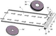
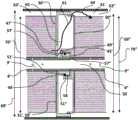
图1是部分组装的螺旋卷式膜模块的部分剖切透视图,其中包括用于指示轴向进料流动和径向向内的渗透物流动的箭头。Figure 1 is a perspective view, partially cut away, of a partially assembled spiral wound membrane module including arrows to indicate axial feed flow and radially inward permeate flow.
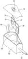
图2a是透视图,展示了从渗透物管退卷的膜片、以及端盖,端盖可以用于覆盖相反卷面的一部分以引起从外周边表面到在下游端上且靠近渗透物管的区域的径向流动。Figure 2a is a perspective view showing the membrane unwound from the permeate tube, and an end cap that may be used to cover a portion of the opposing roll to induce a gap from the outer peripheral surface to the membrane on the downstream end near the permeate tube. Regional radial flow.
图2b是透视图,展示了卷起的螺旋卷式模块(对应于图2a)以及部分地遮挡卷面并且引起径向流动的端盖。箭头展示了进料径向流动,其中浓缩物在渗透物管附近从进料通道区域中移除。Figure 2b is a perspective view showing the coiled spiral wound module (corresponding to Figure 2a) and the end caps partially shielding the coil and inducing radial flow. Arrows illustrate feed radial flow where concentrate is removed from the feed channel region near the permeate tube.
图3是螺旋卷式膜模块组件的部分剖切透视图,示出了位于压力容器内的螺旋卷式膜模块,其包括相邻的第一和第二螺旋卷式模块。3 is a partially cutaway perspective view of a spiral wound membrane module assembly showing the spiral wound membrane module within a pressure vessel including adjacent first and second spiral wound modules.
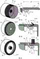
图4a、图4b、和图4c示出了在穿过外环的导管位置处,具有三个不同端盖组件的螺旋卷式模块末端的透视图(左侧)以及对应的截面(右侧)。对于这三个图,环上的进料流动阻器相应地包括a)围绕其外直径的连续螺纹;b)柔性盐水密封件;以及c)扩展的重叠开口环。Figures 4a, 4b, and 4c show perspective views (left) and corresponding cross-sections (right) of the end of a spiral wound module with three different end cap assemblies at the location of the conduit through the outer ring . For these three figures, the feed flow resistors on the rings respectively include a) a continuous thread around its outer diameter; b) a flexible brine seal; and c) an expanding overlapping split ring.
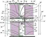
图5a、图5b、和图5c示出了穿过三对不同的相邻端盖组件的截面,每对端盖组件进一步包括至少一个传导导管,该至少一个传导导管穿过端盖组件的内环并且将渗透物收集管的内部空腔连接至压差传感器。每个图展示了进料流体进出路径,其包括在一个卷面的中心附近的开口以及在另一卷面周围的周边路径。Figures 5a, 5b, and 5c show sections through three different pairs of adjacent end cap assemblies, each pair of end cap assemblies further comprising at least one conductive conduit passing through the interior of the end cap assembly. ring and connect the interior cavity of the permeate collection tube to the differential pressure sensor. Each figure shows the feed fluid entry and exit path, which includes an opening near the center of one roll and a peripheral path around the other roll.
图5d是两个相邻端盖组件和在相邻卷面之间且穿过其中的进料流体进出路径的截面。两个不同的连接导管径向地穿过内环和外环中的每一个,每个连接导管流体地连接至压差传感器。Figure 5d is a cross-section of two adjacent end cap assemblies and the feed fluid entry and exit paths between and through adjacent laps. Two different connecting conduits run radially through each of the inner and outer rings, each connecting conduit being fluidly connected to a differential pressure sensor.
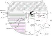
图6a是螺旋卷式膜模块在压力容器内的剖视图。模块包括穿过端盖组件的外环的连接导管、以及在外环内的压差传感器。Figure 6a is a cross-sectional view of a spiral wound membrane module inside a pressure vessel. The module includes connecting conduits passing through the outer ring of the end cap assembly, and a differential pressure sensor within the outer ring.
图6b是容器、模块、和端盖组件在连接导管与压差传感器的位置处的截面。连接导管将压差传感器流体地连接至模块与容器之间的周边空间。Figure 6b is a cross-section of the container, module, and end cap assembly at the location where the conduit connects to the differential pressure sensor. A connecting conduit fluidly connects the differential pressure sensor to the peripheral space between the module and the container.
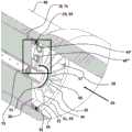
图7a是包括两个连接导管的螺旋卷式膜模块的剖视图,每个连接导管流体地连接至压差传感器。渗透物限流器位于渗透物收集管的内部空腔内、在渗透物收集管的密封构件与多孔段之间。Figure 7a is a cross-sectional view of a spiral wound membrane module comprising two connection conduits, each fluidly connected to a differential pressure sensor. A permeate flow restrictor is located within the interior cavity of the permeate collection tube between the sealing member and the porous section of the permeate collection tube.
图7b提供了图7a中的区域的放大透视图。Figure 7b provides an enlarged perspective view of the area in Figure 7a.
图8是示出端盖组件的另一个实施例的截面图,示出了包括可拉伸薄膜的压力传感器的另一个实施例,所述可拉伸薄膜防止流过连接导管并且包括电阻应变仪。8 is a cross-sectional view showing another embodiment of an end cap assembly showing another embodiment of a pressure sensor including a stretchable membrane that prevents flow through a connecting conduit and includes a resistive strain gauge .
图9是示出适用于本主题压力传感器的电路的示意图。FIG. 9 is a schematic diagram showing a circuit suitable for use with the subject pressure sensor.
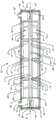
图10是螺旋卷式膜模块组件的截面图,该螺旋卷式膜模块组件包括在压力容器内以串联关系轴向对齐的多个螺旋卷式膜模块。为了便于描述,未示出端盖组件的特征。10 is a cross-sectional view of a spiral wound membrane module assembly comprising a plurality of spiral wound membrane modules axially aligned in series relationship within a pressure vessel. For ease of description, features of the end cap assembly are not shown.
图11是保护壳体以及其中的电子部件的分解图,电子部件包括微处理器、LoRa发射器、电池和天线。Figure 11 is an exploded view of the protective case and the electronic components therein, including the microprocessor, LoRa transmitter, battery and antenna.
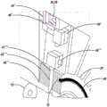
图12a是螺旋卷式膜模块的剖视图,该螺旋卷式膜模块包括两个保护壳体,每个保护壳体都适合包封微处理器和LoRa发射器。其中一个保护壳体是楔形的,以装配在径向延伸的支撑件之间的区域内。Figure 12a is a cross-sectional view of a spiral-wound membrane module comprising two protective housings, each suitable for enclosing a microprocessor and a LoRa transmitter. One of the protective casings is wedge-shaped to fit in the area between the radially extending supports.
图12b提供了图12a中的某区域的放大透视图,该区域包括保护壳体,该保护壳体的邻近于卷面的最近表面与该卷面偏离。Figure 12b provides an enlarged perspective view of an area in Figure 12a that includes a protective casing whose closest surface adjacent to the roll is offset from the roll.
具体实施方式Detailed ways
螺旋卷式膜模块包括围绕渗透物收集管卷绕的一个或多个包膜和进料间隔片。虽然螺旋卷式构型最常用于反渗透(RO)和纳滤(NF),但是本发明也特别适用于低压应用,比如超滤(UF)和微滤(MF)。Spiral wound membrane modules include one or more envelopes and feed spacers wound around a permeate collection tube. While the spiral wound configuration is most commonly used for reverse osmosis (RO) and nanofiltration (NF), the invention is also particularly suitable for low pressure applications such as ultrafiltration (UF) and microfiltration (MF).
图1中用2概括示出了代表性的螺旋卷式膜模块。通过围绕中空渗透物收集管(8)同心地卷绕包膜(4)以及可选的(多个)进料间隔片(“进料间隔件”)以形成交替的包膜(4)和进料通道(6)来形成模块(2)。每个包膜(4)优选地包括两段大致矩形的膜片(10,10')。每段膜片(10,10')通常包括膜侧或前侧以及支撑侧或后侧。通过将膜片(10,10')叠加并将其边缘对齐来形成包膜(4)。在优选的实施例中,这些膜片段(10,10')环绕渗透物间隔片,渗透物间隔片形成了渗透物通道(12)。此夹心型结构例如通过密封剂(15)沿三个边缘(16,18,20)固定在一起以形成包膜(4),而第四边缘(即,“近侧边缘”(22))抵接渗透物收集管(8),使得包膜(4)的内部(和渗透物通道(12),其可以可选地由渗透物间隔片形成)与沿着渗透物收集管(8)的长度的一部分延伸的孔洞(24)处于流体连通。模块(2)可以包括单一包膜或各自被相邻的进料通道(6)隔开的多个包膜(4)。在所展示的实施例中,通过将相邻定位的膜叶片包的后侧表面结合来形成包膜(4)。膜叶片包包括大致矩形的膜片(10),该膜片自身折叠以限定两个膜“叶片”,其中每个叶片的前侧面向彼此,并且折痕与包膜(4)的近侧边缘(22)轴向对齐,即与渗透物收集管(8)平行。形成进料通道(6)的进料间隔片被示出为位于折叠后的膜片(10)的相向的前侧之间。虽然未示出,但是组件中还可以包括附加的中间层。膜叶片包及其制造的代表性示例在US 7875177和US 8608964中有进一步描述。用于反渗透的原型膜是通过多官能胺和酰卤单体在多孔支撑件上的界面聚合来制作的FilmTec公司的FT-30TM型膜。A representative spiral-wound membrane module is shown generally at 2 in FIG. 1 . Alternating envelopes (4) and feed spacers are formed by wrapping the envelope (4) and optional feed spacer(s) (“feed spacer”) concentrically around a hollow permeate collection tube (8) Material channel (6) to form module (2). Each envelope (4) preferably comprises two substantially rectangular membrane sections (10, 10'). Each membrane segment (10, 10') generally includes a membrane side or front side and a support side or back side. The envelope (4) is formed by superimposing the membrane sheets (10, 10') and aligning their edges. In a preferred embodiment, these membrane segments (10, 10') surround permeate spacers which form the permeate channels (12). This sandwich-type structure is secured together along three edges (16, 18, 20), such as by sealant (15), to form the envelope (4), while the fourth edge (i.e., the "proximal edge" (22)) connected to the permeate collection tube (8) so that the interior of the envelope (4) (and the permeate channels (12), which may optionally be formed by permeate spacers) are the same as along the length of the permeate collection tube (8) A portion of the extended bore (24) is in fluid communication. The module ( 2 ) may comprise a single envelope or a plurality of envelopes ( 4 ), each separated by adjacent feed channels ( 6 ). In the illustrated embodiment, the envelope ( 4 ) is formed by joining the rear side surfaces of adjacently positioned membrane leaf packs. The membrane leaf pack consists of a generally rectangular membrane sheet (10) that is folded over itself to define two membrane "leaves" where the front sides of each leaf face each other and the folds align with the proximal edge of the envelope (4) (22) is axially aligned, ie parallel to the permeate collection tube (8). The feed spacers forming the feed channels (6) are shown between the facing front sides of the folded membrane (10). Although not shown, additional intermediate layers may also be included in the assembly. Representative examples of membrane vane packs and their manufacture are further described in US7875177 and US8608964. The prototype membrane for reverse osmosis was FilmTec's FT-30TM membrane fabricated by interfacial polymerization of polyfunctional amine and acid halide monomers on a porous support.
在模块制造过程中,可以围绕渗透物收集管(8)的周界来附接渗透物间隔片,其中膜叶片包插在渗透物间隔片之间。渗透物收集管(8)具有外表面(7)、内表面(5)、以及由内表面(5)界定的内部空腔(9)。渗透物收集管(8)沿着轴线(X)在管的相反的第一端与第二端(13’,13)之间延伸,并且多孔段(15)沿着其长度包括多个孔洞(24)。渗透物收集管(8)的多孔段(15)在轴向上位于渗透物收集管的相反两端处的两个远侧段(23,23’)之间。多孔段(15)与远侧段(23,23’)的不同之处在于,多孔段(15)中的孔洞(24)使得液体能够从管的内表面(5)流到其外表面(7),并且还因为这些孔洞将渗透物收集管(8)的内部空腔(9)连接至包膜(4)内的渗透物通道(12)。During module manufacture, permeate spacers may be attached around the perimeter of the permeate collection tube (8), with the membrane vanes interposed between the permeate spacers. The permeate collection tube (8) has an outer surface (7), an inner surface (5), and an inner cavity (9) bounded by the inner surface (5). The permeate collection tube (8) extends along axis (X) between opposite first and second ends (13', 13) of the tube, and the porous section (15) comprises a plurality of holes ( twenty four). The porous section (15) of the permeate collection tube (8) is located axially between two distal sections (23, 23') at opposite ends of the permeate collection tube. The porous section (15) differs from the distal sections (23, 23') in that the holes (24) in the porous section (15) enable the flow of liquid from the inner surface (5) of the tube to its outer surface (7 ), and also because these holes connect the inner cavity (9) of the permeate collection tube (8) to the permeate channel (12) in the envelope (4).
将相邻定位的膜叶片(10,10')的后侧围绕其周边(16,18,20)的一部分进行密封,以围住渗透物通道(12)并形成包膜(4)。用于将渗透物间隔片附接至渗透物收集管的合适技术在US 5538642中进行了描述。围绕沿着轴线(X)延伸的渗透物收集管(8)同心地卷绕或“卷起”包膜(4)和进料间隔件(6)以形成两个卷面(30,32)。然后可以修整模块的卷面,并且可以可选地在卷面与渗透物收集管(8)之间的接合处施加密封剂,如US 7951295中描述的。可以围绕卷式模块的周界卷绕胶带等不可渗透层,如US 8142588和US 8668828中描述的。在替代性实施例中,可以对模块的周边施加多孔胶带或玻璃纤维涂层。参见例如US9623379。The rear sides of adjacently positioned membrane leaves (10, 10') are sealed around a portion of their perimeter (16, 18, 20) to enclose the permeate channel (12) and form an envelope (4). A suitable technique for attaching the permeate spacer to the permeate collection tube is described in US 5538642. The envelope (4) and feed spacer (6) are concentrically wound or "rolled" around the permeate collection tube (8) extending along axis (X) to form two rolls (30, 32). The rolls of the modules can then be trimmed and a sealant can optionally be applied at the junction between the rolls and the permeate collection tube (8), as described in US 7951295. An impermeable layer such as tape may be wound around the perimeter of the roll module as described in US 8142588 and US 8668828. In alternative embodiments, a porous tape or fiberglass coating may be applied to the perimeter of the module. See eg US9623379.
进一步参考图1,在操作中,加压的进料流体(例如,水)被示为穿过卷面(30)即在“上游”进入模块(2),并且在大体轴向方向上流过模块并在箭头(26)所示的方向上在相反卷面(32)、即“下游”处作为浓缩物离开。渗透物沿着总体上由箭头(28)所示的径向向内的渗透物流动路径流动,该渗透物流动路径延伸穿过膜(10,10')并进入包膜(4),在包膜中,渗透物流入孔洞(24)、流过渗透物收集管(8)并在渗透物收集管(8)的端(13,13’)处离开。With further reference to FIG. 1 , in operation, a pressurized feed fluid (e.g., water) is shown entering the module (2) through the coil (30), ie "upstream", and flowing through the module in a generally axial direction. and exits as a concentrate at the opposite volume (32), ie "downstream", in the direction indicated by the arrow (26). The permeate flows along a radially inward permeate flow path generally indicated by arrows (28), which extends through the membrane (10, 10') and into the envelope (4), where In the membrane, the permeate flows into the pores (24), through the permeate collection tube (8) and exits at the ends (13, 13') of the permeate collection tube (8).
图2a和图2b示出了用于创建具有进料径向流动的替代性螺旋卷式模块的一种途径。类似于图1所示的过程,围绕中空渗透物收集管(8)卷绕至少一个包膜(4)以形成具有第一卷面(30)、相反卷面(32)、以及外周边表面(3)的圆筒。然而,通过提供具有多孔外表面(3)的模块(2)以及将端盖组件(31,31’)与这两个相反的卷面(30,32)抵接,可以修改进料流进入和离开卷面(30,32)的位置。在图2b中,第一端盖组件(31)被展示为遮挡第一卷面(30),并且迫使进料流体穿过多孔外周边表面(3)进入进料通道(6)。同时,与相反卷面(32)抵接的端盖组件(31)使得进料穿过渗透物管(8)附近的相反卷面(32)区域离开进料通道(6)。该图展示了在端盖组件(31)上的盐水密封件(39)以防止旁通。如图1所示,进料通道(6)位于模块的两个卷面(30,32)之间,但是进料流经模块的主要方向总体上垂直(不平行)于渗透物收集管。在US 8337698、US 10137416 B2、JP 2013071098 A、和JP 59150505 A中描述了用于获得总体上径向进料流动(无论是向内或向外)的其他途径。Figures 2a and 2b show one approach for creating an alternative spiral wound module with feed radial flow. Similar to the process shown in Figure 1, at least one envelope (4) is wound around the hollow permeate collection tube (8) to form a first wrap (30), an opposite wrap (32), and an outer peripheral surface ( 3) The cylinder. However, by providing the module (2) with a porous outer surface (3) and abutting the end cap assembly (31, 31') against these two opposing rolls (30, 32), it is possible to modify the feed flow entry and Leave the position of roll surface (30, 32). In Figure 2b, the first end cap assembly (31 ) is shown shielding the first roll (30) and forcing the feed fluid through the porous outer peripheral surface (3) into the feed channel (6). Simultaneously, the end cap assembly (31 ) abutting the opposing lap (32) allows the feed to exit the feed channel (6) through the region of the opposing lap (32) near the permeate tube (8). This figure shows the brine seal (39) on the end cap assembly (31) to prevent bypass. As shown in Figure 1, the feed channel (6) is located between the two volumes (30, 32) of the module, but the main direction of feed flow through the module is generally perpendicular (not parallel) to the permeate collection tube. Other approaches for obtaining generally radial feed flow (whether inward or outward) are described in US 8337698, US 10137416 B2, JP 2013071098 A, and JP 59150505 A.
图3展示了在容器(40)内的多个螺旋卷式模块(3),其形成螺旋卷式模块组件(21)。端盖组件(31)可以影响系统中模块之间的流体流的流动。可以在模块(2)的一个或两个卷面(30或32)上定位端盖组件(31)(还被称为并用作“抗伸缩装置”)。图4a、图4b、图4c、图5a、图5b、图5c和图5d示出了端盖组件的不同实施例。为了便于描述两个相邻的端盖组件,图3、图5a、图5b、图5c和图5d将相邻的第一模块(2’)和第二模块(2”)的相邻卷面分别编号为第一卷面(30’)和第二卷面(30”)。在图3中,接着将模块相反端上的卷面编号为第一相反卷面(32’)和第二相反卷面(32”)。以类似的方式,对相邻的第一和第二模块上的其他特征(例如,渗透物收集管(8’,8”))的描述分别用单引号和双引号示出。这种命名和措辞不旨在标识进料流动方向,并且进料溶液可以沿从第一卷面朝向第二卷面的方向移动,但是进料溶液也可以沿相反方向流动。当模块(2)上存在单一端盖组件(31)时,对于本发明,该单一端盖组件优选地位于具有轴向流动设计的模块的进料入口端上、以及具有径向流动设计的模块的进料出口端上。然而,本领域技术人员应了解的是,仅具有单一端盖组件(31)的模块(2)还可以在压力容器(40)内相反地定向。在更优选的实施例中,端盖组件(31)抵接每个螺旋卷式膜模块(2)的两个卷面(30,32),但是每个端盖组件(31)上的特征可以不同。Figure 3 shows a plurality of spiral wound modules (3) within a container (40) forming a spiral wound module assembly (21). The end cap assembly (31) can affect the flow of fluid flow between modules in the system. An end cap assembly (31 ) (also known and used as an "anti-telescopic device") may be positioned on one or both rolls (30 or 32) of the module (2). Figures 4a, 4b, 4c, 5a, 5b, 5c and 5d illustrate different embodiments of end cap assemblies. In order to facilitate the description of two adjacent end cap assemblies, Fig. 3, Fig. 5a, Fig. 5b, Fig. 5c and Fig. 5d will be adjacent to the adjacent first module (2') and second module (2") They are respectively numbered as the first roll (30') and the second roll (30"). In Figure 3, the coils on the opposite ends of the modules are then numbered as a first opposing coil (32') and a second opposing coil (32"). In a similar manner, adjacent first and second Descriptions of other features on the module (eg, permeate collection tubes (8', 8")) are shown in single and double quotes, respectively. This nomenclature and phraseology is not intended to identify the direction of feed flow, and the feed solution may move in a direction from the first lap towards the second lap, but the feed solution may also flow in the opposite direction. When there is a single end cap assembly (31) on a module (2), for the present invention, this single end cap assembly is preferably located on the feed inlet end of a module with an axial flow design, and a module with a radial flow design On the feed outlet end. However, it will be appreciated by those skilled in the art that modules (2) having only a single end cap assembly (31) could also be oriented in reverse within the pressure vessel (40). In a more preferred embodiment, the end cap assemblies (31) abut against both wraps (30, 32) of each spiral wound membrane module (2), however features on each end cap assembly (31) may different.
端盖组件(31)的构型没有特别限制,但它可以包括内环(57)、外环(33)、或这两者。端盖组件(31)抵接卷面(30,32)、并且优选地附连(例如,通过粘合剂、旋转焊接、胶带)至螺旋卷式模块上的至少一个位置。附接位置可以选自渗透物收集管(8)、模块的外周边表面(3)、以及抵接的卷面(30,32)。在图3中,为了便于描述,没有详细示出端盖组件。在图4a、图4b、和图4c中,每个端盖组件的透视图省去了在相关联截面中更容易识别的特征。然而,这些实施例(以及那些其他附图)绝不是限制性的,并且可以存在未示出的额外特征。例如,如图5a至图5d和图7a所示,端盖组件还可以包括互锁特征(58),这些互锁特征被适配为与相邻定位的分离模块的对应端盖可释放地接合,所述互锁特征(58)可以创建或维持密封构件(48)在相邻模块(2)上的密封表面(51)之间的压缩。在优选的实施例中,端盖组件(31)包括连接导管(45),该连接导管径向地穿过端盖组件(31)的一部分、限定了在导管内端(46)与导管外端(47)之间的流体通路。压差传感器(49)附接至端盖组件(31)并且流体地连接至连接导管(45)的流体通路。The configuration of the end cap assembly (31) is not particularly limited, but it may include an inner ring (57), an outer ring (33), or both. The end cap assembly (31) abuts the roll faces (30, 32), and is preferably attached (eg, by adhesive, spin welding, tape) to at least one location on the spiral wound module. The attachment location may be selected from the permeate collection tube (8), the outer peripheral surface (3) of the module, and the abutting rolls (30, 32). In FIG. 3 , for ease of description, the end cap assembly is not shown in detail. In Figures 4a, 4b, and 4c, the perspective views of each end cap assembly omit features that are more easily identified in the associated cross-section. However, these embodiments (and those of the other figures) are by no means limiting and there may be additional features not shown. For example, as shown in FIGS. 5a-5d and 7a, the end cap assembly may also include interlocking features (58) adapted to releasably engage with corresponding end caps of adjacently positioned split modules. , the interlocking feature (58) may create or maintain compression of the sealing member (48) between sealing surfaces (51 ) on adjacent modules (2). In a preferred embodiment, the end cap assembly (31) includes a connecting conduit (45) that passes radially through a portion of the end cap assembly (31) and defines a connection between the conduit inner end (46) and the conduit exterior. The fluid passage between the ends (47). A differential pressure sensor (49) is attached to the end cap assembly (31) and is fluidly connected to the fluid passage of the connecting conduit (45).
在几个实施例中,模块(2)的至少一端优选地包括端盖组件(31),该端盖组件具有外环(33),该外环限定了端盖的第一外周边(36)并且包括在该端盖组件(31)与该腔室(41)的内周边表面(60)之间径向延伸的环形进料流动阻器(19)。该径向延伸的环形进料流动阻器在操作中适合于在相关联的端盖组件(31)与容器腔室(41)的内周边表面(60)之间提供用于进料流动的受限路径,使得进料流的至少75%在进料通道(6)内穿过模块,而不是穿过端盖组件(31)与内周边表面(60)之间。图4a、图4b、和图4c展示了具有不同的进料流动阻器(19)的端盖组件(31)的三个实施例。这些端盖组件包括旨在允许一定旁通的紧密配合的螺纹外表面、在端盖组件(31)上的环形凹槽(37)内的常规盐水密封件(39)、以及同样在环形凹槽(37)内的重叠开口环。在优选的实施例中,螺旋卷式模块包括位于第一外环(33)的第一外周边(36)上的环形凹槽(37),并且环形凹槽(37)包括径向延伸的环形进料流动阻器(19),该进料流动阻器是适合与腔室(41)的内周边表面(60)接合的盐水密封件(39)。对于这三种情况中的每种情况,双向水平箭头指示环形进料流动阻器(19)在流动期间将在其上引起压降的主要区域。In several embodiments, at least one end of the module (2) preferably includes an end cap assembly (31) having an outer ring (33) defining a first outer perimeter (36) of the end cap And comprising an annular feed flow resistor (19) extending radially between the end cap assembly (31) and the inner peripheral surface (60) of the chamber (41). The radially extending annular feed flow resistor is operatively adapted to provide a restricted flow for feed flow between the associated end cap assembly (31) and the inner peripheral surface (60) of the vessel chamber (41). The path is restricted so that at least 75% of the feed flow passes through the module within the feed channel (6) rather than between the end cap assembly (31) and the inner peripheral surface (60). Figures 4a, 4b, and 4c illustrate three embodiments of end cap assemblies (31 ) with different feed flow resistors (19). These end cap assemblies include a tight-fitting threaded outer surface designed to allow some bypass, a conventional brine seal (39) in an annular groove (37) on the end cap assembly (31), and also in the annular groove Overlapping split rings inside (37). In a preferred embodiment, the spiral wound module comprises an annular groove (37) on the first outer periphery (36) of the first outer ring (33), and the annular groove (37) comprises a radially extending annular A feed flow resistor (19) which is a brine seal (39) adapted to engage the inner peripheral surface (60) of the chamber (41). For each of these three cases, the bi-directional horizontal arrow indicates the main area over which the annular feed flow resistor (19) will induce a pressure drop during flow.
在优选的实施例中,外环(33’)包括进料流动阻器(19)并且环绕在第一卷面(30)处连接至第一进料通道(6)的进料流体进出路径(65)。进料流体进出路径(65)可以包括在端盖组件(31)中的至少一个端盖孔口(35)。图5a、图5b、图5c、和图5d中相邻模块(3’,3”)的图中示出了进料流体路径(61),该进料流体路径包括进料流体进出路径(65)并且将第一进料通道(6’)与第二进料通道(6”)相连。进料流体路径(61)穿过位于相邻模块(2’,2”)的相邻卷面(第一卷面(30’)与第二卷面(30”))之间的中心区域(63)。In a preferred embodiment, the outer ring (33') includes a feed flow resistor (19) and surrounds the feed fluid inlet and outlet path ( 65). The feed fluid access path (65) may include at least one end cap aperture (35) in the end cap assembly (31). Figures 5a, 5b, 5c, and 5d are views of adjacent modules (3', 3") showing feed fluid paths (61) that include feed fluid in and out paths (65 ) and connect the first feed channel (6') with the second feed channel (6"). The feed fluid path (61) passes through the central area ( 63).
在优选的实施例中,相邻的端盖组件(31’,31”)被配置且被布置为能够产生在第二卷面(30”)周围的周边路径(64),该周边路径将中心区域(63)和第二周边空间(62”)流体地连接,其中,第二周边空间(62”)位于第二螺旋卷式模块(2”)的第二外周边表面(3”)与腔室(41)的内周边表面(60)之间;在图5a、图5b和图5c中,第二螺旋卷式模块(2”)的外周边表面(3”)是多孔的,并且周边路径(64)是相邻模块的进料通道(6’,6”)之间的进料流体路径(61)的一部分。In a preferred embodiment, adjacent end cap assemblies (31', 31") are configured and arranged to create a peripheral path (64) around the second roll (30") which will center The region (63) is fluidly connected to the second peripheral space (62"), wherein the second peripheral space (62") is located between the second outer peripheral surface (3") of the second spiral wound module (2") and the cavity between the inner peripheral surface (60) of the chamber (41); in Figures 5a, 5b and 5c, the outer peripheral surface (3") of the second spiral wound module (2") is porous and the peripheral path (64) is part of the feed fluid path (61) between the feed channels (6', 6") of adjacent modules.
其他优选的实施例涉及对不同区域之间的水流动的相对阻力。对于具有相邻的端盖组件(31’,31”)位于对应卷面(30’,30”)上的相邻的第一和第二螺旋卷式模块(2’,2”),可以确定相邻区域之间的压力差和旁通体积流量(在卷面周围)。考虑三个区域:a)径向地位于第一螺旋卷式模块(2’)的第一外周边表面(3’)与腔室(41)的内周边表面(60)之间的第一周边空间(62’),b)在卷面(30’,30”)之间、抵接相邻的第一和第二端盖组件(31’,31”)的中心区域(63),以及c)径向地位于第二螺旋卷式模块(2”)的第二外周边表面(3”)与腔室(41)的内周边表面(60)之间的第二周边空间(62”)。可以测量对从第一周边空间(62’)流到中心区域(63)的旁通水流的第一阻力,以及对从中心区域(63)流到第二周边空间(62”)的旁通流的第二阻力。在优选的实施例中,对旁通水流的第一阻力是对旁通水流的第二阻力的至少十倍。为了达到本发明的这方面的目的,在25℃并在第一周边空间(62’)与中心区域(41)之间的压力差(ΔP)为0.25巴(25千帕,~3.6psi)的条件下,测量此水体积流量(Q)的相对阻力(ΔP/Q)。Other preferred embodiments relate to relative resistance to water flow between different zones. For adjacent first and second spiral wound modules (2', 2") having adjacent end cap assemblies (31', 31") on corresponding roll surfaces (30', 30"), it can be determined that Pressure difference and bypass volume flow between adjacent zones (around the coil). Consider three zones: a) radially located on the first outer peripheral surface (3') of the first spiral wound module (2') ) and the first peripheral space (62') between the inner peripheral surface (60) of the chamber (41), b) between the rolling surfaces (30', 30"), abutting adjacent first and second The central region (63) of the two end cap assemblies (31', 31"), and c) are radially located between the second outer peripheral surface (3") of the second spiral wound module (2") and the cavity (41 ) between the inner peripheral surface (60) of the second peripheral space (62"). The first resistance to bypass flow from the first peripheral space (62') to the central area (63) and the bypass flow from the central area (63) to the second peripheral space (62") can be measured The second resistance. In a preferred embodiment, the first resistance to the bypass water flow is at least ten times the second resistance to the bypass water flow. In order to achieve the purpose of this aspect of the present invention, at 25 ° C and at the Under the condition that the pressure difference (ΔP) between a peripheral space (62') and the central area (41) is 0.25 bar (25 kPa, ~3.6 psi), measure the relative resistance (ΔP) of the water volume flow rate (Q) /Q).
在其他优选的实施例中,第一和第二周边空间(62’,62”)是轴向延伸的导管,其各自的厚度大于对应螺旋卷式模块(2’,2”)的进料通道(6’,6”)的厚度两倍。此外,在一些实施例中,模块(2)上的至少一个端盖组件(31)的最小直径(69)比其轴向中心(71)处的模块平均直径(70)大了进料通道厚度的至少四倍(更优选地八倍)。最小直径(69)被定义为可以将模块以40磅力推到其中的最小容器直径,尤其对应于柔性部件(例如,盐水密封件(39))处于其最大压缩状态。In other preferred embodiments, the first and second peripheral spaces (62', 62") are axially extending ducts, each having a thickness greater than the feed channel of the corresponding spiral wound module (2', 2") (6', 6") twice the thickness. Furthermore, in some embodiments, the minimum diameter (69) of at least one end cap assembly (31) on the module (2) is smaller than that at its axial center (71) The module average diameter (70) is at least four times (more preferably eight times) larger than the feed channel thickness. The minimum diameter (69) is defined as the smallest vessel diameter into which the module can be pushed with 40 lbs of force, specifically corresponding to The flexible component (eg saline seal (39)) is at its maximum compression.
在一些优选的实施例中,端盖组件(31)包括居中定位的、轴向对齐的端盖内环(57)。端盖内环(57)可以固定并密封至渗透物收集管(8)或者它可以同心地环绕从渗透物收集管(8)延伸的互连管(图10中示出的(43))。在图6a和图7a所示的实施例中,端盖内环(57)围绕渗透物收集管(8)同心地装配。端盖内环(57)可以通过紧密同心配合、粘合剂、焊接等进行固定。在优选的实施例中,内环(57)与外环(33)之间的至少一个孔口(35)为模块(2)提供进料流体进出路径。In some preferred embodiments, the end cap assembly (31) includes a centrally located, axially aligned end cap inner ring (57). The end cap inner ring (57) may be fixed and sealed to the permeate collection tube (8) or it may concentrically surround an interconnecting tube (shown (43) in Figure 10) extending from the permeate collection tube (8). In the embodiment shown in Figures 6a and 7a, the end cap inner ring (57) fits concentrically around the permeate collection tube (8). The end cap inner ring (57) can be secured by tight concentric fit, adhesive, welding, etc. In a preferred embodiment, at least one orifice (35) between the inner ring (57) and the outer ring (33) provides a feed fluid access path for the module (2).
在图6a和图7a中,端盖内环(57)通过多个径向延伸的支撑件(34)、例如“辐条”连接至外环(33),并且所示支撑件(34)被端盖孔口(35)分开,这些端盖孔口为模块(2)提供进料流体进出路径(65),即,使得取决于模块相对于进料流动方向的取向,液体流入或流出模块(2)的卷面(30)。总体上由实线箭头指示了代表性的进料流体进出路径(65)。在US5128037、US 5851267、US 6632356、US 8425773、和WO 2014/151695中描述了毂与辐条端盖的代表性示例。如图6b中最佳所示,限定端盖的外周边(36)的外环(33)可以总体上与模块(2)的外周边表面(3)共同延伸并且包括环形凹槽(37)以及位于环形凹槽(37)中的进料流动阻器(19)(例如,盐水密封件(39)),该进料流动阻器被适配为与压力容器(40)的内周边表面(60)密封接合。如之前所述,当位于压力容器中时,进料流动阻器(19)阻止流体绕开模块(2)并沿着模块(2)的外周边表面(3)与压力容器(40)的内周边表面(60)之间的周边空间(62)流动。图3a、图3b、和图3c已经展示了几种不同的限流器,并且在以下文献中描述了代表性示例:US 6299772、US 8110016、和WO 2017/019282。可以使用多种类型的密封件,例如,O形环、人字形密封件、U形密封件、开口环密封件等。参见例如:US 6224767、US7198719、US 8377300、US8388842、US 8377300以及US 9381469。In Figures 6a and 7a, the end cap inner ring (57) is connected to the outer ring (33) by a plurality of radially extending supports (34), such as "spokes", and the supports (34) shown are The cap apertures (35) are separated, and these end cap apertures provide a feed fluid path (65) for the module (2), i.e., such that liquid flows into or out of the module (2) depending on the orientation of the module relative to the direction of feed flow. ) roll surface (30). Representative feed fluid entry and exit paths (65) are indicated generally by solid arrows. Representative examples of hub and spoke end caps are described in US5128037, US 5851267, US 6632356, US 8425773, and WO 2014/151695. As best shown in Figure 6b, the outer ring (33) defining the outer perimeter (36) of the end cap may be generally coextensive with the outer perimeter surface (3) of the module (2) and include an annular groove (37) and A feed flow resistor (19) (e.g., a brine seal (39)) located in the annular groove (37) adapted to engage the inner peripheral surface (60) of the pressure vessel (40) ) sealed joint. As previously stated, when located in the pressure vessel, the feed flow resistor (19) prevents fluid from bypassing the module (2) and passing along the outer peripheral surface (3) of the module (2) to the interior of the pressure vessel (40). The peripheral space (62) between the peripheral surfaces (60) flows. Figures 3a, 3b, and 3c have shown several different flow restrictors, and representative examples are described in: US 6299772, US 8110016, and WO 2017/019282. Various types of seals may be used, eg, O-rings, chevron seals, U-shaped seals, split ring seals, and the like. See for example: US 6224767, US7198719, US 8377300, US8388842, US 8377300 and US 9381469.
优选地,螺旋卷式膜模块(2)的至少一个端盖组件(31)包括连接导管(45),该连接导管限定了从位于外环(33)的外周边(36)处的导管外端(47)径向向内延伸到位于外环(33)内(例如,在与支撑件(34)相邻并与模块(2)的该端处于流体连通的位置)的导管内端(46)的流体通路。导管外端(47)优选地在轴向上位于进料流动阻器(19)与模块(2)的相反卷面(32)之间,例如,被适配为与位于模块(2)的外周边表面(3)与压力容器(40)的内周边表面(60)之间的周边空间(62)流体连通。更优选地,导管外端(47)在轴向上位于进料流动阻器(19)与模块的第一(即,最近)卷面(30)之间。在另一优选的实施例中,端盖组件(31)位于被配置用于使进料轴向流动的模块(2)的“上游”端上,并且导管外端(47)位于进料流动阻器(19)的“下游”。在优选的替代性实施例中,端盖组件(31)位于被配置用于使进料径向流动的模块(2)的“下游”端上,并且导管外端(47)位于进料流动阻器(19)的“上游”。在任一情况下,连接导管(45)提供周边空间(62)与中心区域(63)(位于第一卷面与第二卷面(30’,30”)之间)之间的通路。Preferably, at least one end cap assembly (31) of the spiral wound membrane module (2) comprises a connecting conduit (45) defining (47) extends radially inwardly to the inner end of the conduit (46) located within the outer ring (33), for example at a location adjacent to the support (34) and in fluid communication with the end of the module (2) fluid pathway. The outer end (47) of the conduit is preferably located axially between the feed flow resistor (19) and the opposite volume (32) of the module (2), eg The peripheral surface (3) is in fluid communication with a peripheral space (62) between the inner peripheral surface (60) of the pressure vessel (40). More preferably, the conduit outer end (47) is located axially between the feed flow resistor (19) and the first (ie nearest) volume (30) of the module. In another preferred embodiment, the end cap assembly (31) is located on the "upstream" end of the module (2) configured for axial flow of the feed, and the conduit outer end (47) is located at the feed flow resistance. "Downstream" of device (19). In a preferred alternative embodiment, the end cap assembly (31) is located on the "downstream" end of the module (2) configured for radial flow of the feed, and the conduit outer end (47) is located at the feed flow resistance. "Upstream" of device (19). In either case, the connecting duct (45) provides access between the peripheral space (62) and the central region (63) between the first and second rolls (30', 30").
允许流体围绕盐水密封件绕开的类似开口已经描述于:JP 05287789、JP62049902、US 5128037、US 7208088、US 8778182、和US 2013/0161258。US 8377300展示了端盖的侧面中的开口,用于移除盐水密封件。如下所述,在本发明中,通过适合用于测量压差的阻挡件来防止流体流过连接导管(45)。Similar openings that allow fluid to bypass around saline seals have been described in: JP 05287789, JP62049902, US 5128037, US 7208088, US 8778182, and US 2013/0161258. US 8377300 shows an opening in the side of the end cap for removal of the brine seal. As described below, in the present invention, fluid flow through the connecting conduit (45) is prevented by a barrier suitable for measuring differential pressure.
在优选实施例中,该螺旋卷式模块组件的特征在于端盖组件(31),该端盖组件包括微处理器、天线、LoRa发射器、以及连接至该微处理器的至少一个传感器。微处理器(79)和LoRa发射器(80)可以是单独的并且相连接,但是这些部件也可以组合在单一模块中,如muRata型1SJ无线模块中呈现的。在一些实施例中,多个不同的传感器连接至该微处理器。图4至图8中展示了压差传感器,但可以有用地将许多其他传感器类型纳入端盖组件(31)中。端盖组件(31)内的适当传感器可以适合测量对应于压力、压差、流量、电导率、声强度或光强度的值。该LoRa发射器适合通过以400MHz至1000MHz之间的射频提供顺序线性调频信号来将测得的值发射至接收器或网关。In a preferred embodiment, the spiral wound module assembly is characterized by an end cap assembly (31) comprising a microprocessor, an antenna, a LoRa transmitter, and at least one sensor connected to the microprocessor. The microprocessor (79) and LoRa transmitter (80) can be separate and connected, but these components can also be combined in a single module, as presented in the muRata type 1SJ wireless module. In some embodiments, a number of different sensors are connected to the microprocessor. A differential pressure sensor is illustrated in Figures 4-8, but many other sensor types could usefully be incorporated into the end cap assembly (31). Appropriate sensors within the end cap assembly (31) may be adapted to measure values corresponding to pressure, differential pressure, flow, conductivity, sound intensity or light intensity. This LoRa transmitter is suitable for transmitting measured values to a receiver or gateway by providing a sequential chirp signal at a radio frequency between 400MHz and 1000MHz.
LoRa(是长距离(Long Range)的缩写)是衍射自线性调频扩频(CSS)技术的一种调制技术。虽然LoRa发射器可能能够长距离使用(例如,甚至大于1200km),但在本发明的优选实施例中,LoRa发射器和接收器是在同一建筑物内并且优选地在一百米之内。已经发现,LoRa尤其适于水下传输,并且因此可以更容易地从浸没在填充有水的容器中的螺旋卷式模块内发射信号。LoRa联盟已经定义了以下区域的操作频率:在北美洲为902-928MHz,在欧洲为867-869MHz,在中国为470-510MHz,在韩国和日本为920-925MHz,并且在印度为865-867MHz。LoRaWAN是用于在LoRa设备之间传输信息的优选的通信协议。进一步在(B.O.A.Yousuf,E.Rochester和M.Ghaderi,“Throughput,coverage and scalability oflora lpwan for internet of things[lora lpwan物联网的吞吐量、覆盖范围和可扩展性]”,IEEE/ACM服务质量国际研讨会(IWQoS),2018年6月)中描述了LoRa,该文章通过引用并入本文。LoRa (short for Long Range) is a modulation technique derived from Chirp Spread Spectrum (CSS) technology. While a LoRa transmitter may be capable of long distances (eg, even greater than 1200km), in a preferred embodiment of the invention, the LoRa transmitter and receiver are within the same building and preferably within a hundred meters. It has been found that LoRa is particularly suitable for underwater transmission, and thus can more easily transmit signals from within a spiral-wound module submerged in a water-filled container. The LoRa Alliance has defined operating frequencies for the following regions: 902-928MHz in North America, 867-869MHz in Europe, 470-510MHz in China, 920-925MHz in Korea and Japan, and 865-867MHz in India. LoRaWAN is the preferred communication protocol for transferring information between LoRa devices. Further in (B.O.A. Yousuf, E. Rochester and M. Ghaderi, "Throughput, coverage and scalability oflora lpwan for internet of things", IEEE/ACM Quality of Service International LoRa is described in a workshop (IWQoS), June 2018), which is incorporated herein by reference.
在优选实施例中,端盖组件(31)进一步包括保护壳体(90),该保护壳体包封了微处理器(79)和LoRa发射器(80)两者。如图11所示,保护壳体(90)具有两个可分开的部分:本体段(75)和盖子段(76)。保护壳体(90)的这两个可分开的段(75,76)可以可逆地密封在一起。在其他实施例中,保护壳体(90)是热固性或热塑性聚合物材料制成的整体式结构(例如,“灌封的”)。保护壳体(90)适合将微处理器(79)和LoRa发射器(80)两者与端盖组件(31)内的流体隔离。In a preferred embodiment, the end cap assembly (31) further includes a protective housing (90) enclosing both the microprocessor (79) and the LoRa transmitter (80). As shown in Figure 11, the protective case (90) has two separable parts: a body section (75) and a cover section (76). The two separable segments (75, 76) of the protective housing (90) can be reversibly sealed together. In other embodiments, protective housing (90) is a unitary structure (eg, "potted") of a thermoset or thermoplastic polymer material. The protective housing (90) is adapted to isolate both the microprocessor (79) and the LoRa transmitter (80) from the fluid within the end cap assembly (31).
在一些实施例中,保护壳体进一步包封了电池、天线、或电池及天线两者。在保护壳体中包含电池有利于包括两个可逆地密封在一起的可分开的部分的保护壳体。保护壳体还可以包封为了使传感器与中央处理单元电连接而需要的其他电子部件(81)。(例如,模数转换器或比较器)。在图11中,微处理器(79)、LoRa发射器(80)和其他电子部件(81)安装在同一个印刷电路板(77)上。接线将电池(78)、天线(82)和传感器(83,84)连接至微处理器(经由电路板)。In some embodiments, the protective case further encloses the battery, the antenna, or both the battery and the antenna. Containing the battery in the protective case facilitates a protective case comprising two separable parts that are reversibly sealed together. The protective housing may also enclose other electronic components (81) required to electrically connect the sensor to the central processing unit. (for example, an analog-to-digital converter or a comparator). In Figure 11, the microprocessor (79), LoRa transmitter (80) and other electronic components (81) are mounted on the same printed circuit board (77). Wiring connects the battery (78), antenna (82) and sensors (83, 84) to the microprocessor (via the circuit board).
保护壳体还可以包含传感器。例如,温度传感器可能不需要接触保护壳体周围的流体。在其他实施例中,保护壳体环绕传感器和流体导管两者,其中,该流体导管在传感器与端盖组件的、位于保护壳体外的区域之间提供流体路径。将传感器定位在保护壳体内可以抵抗较高的操作压力来物理地支撑传感器,并且流体导管可以允许其通过接触来测量与进料流和渗透流相关联的液体的特性。在另外的其他实施例中,保护壳体外的接线可以将微处理器连接至保护壳体外的传感器。示例传感器可以包括图4至图8所示的压差传感器,但也可以或替代地可以将许多其他传感器类型连接至微处理器。至少一个传感器连接至微处理器,其中,所述传感器适合测量对应于压力、压差、流量、电导率、pH、声强度或光强度的值,并且其中,LoRa发射器适合通过以400MHz至1000MHz之间的射频提供顺序线性调频信号来发射所述测得的值。传感器可以使用直接安装或接线直接连接至微处理器(或经由附接的印刷电路板)。The protective housing may also contain sensors. For example, a temperature sensor may not need to come into contact with the fluid surrounding the protective housing. In other embodiments, the protective housing surrounds both the sensor and the fluid conduit, wherein the fluid conduit provides a fluid path between the sensor and a region of the end cap assembly that is outside the protective housing. Locating the sensor within a protective housing can physically support the sensor against higher operating pressures, and the fluid conduits can allow it to measure properties of liquids associated with the feed and permeate streams through contact. In still other embodiments, wiring outside the protective housing may connect the microprocessor to sensors outside the protective housing. Example sensors may include the differential pressure sensors shown in FIGS. 4-8 , although many other sensor types may also or alternatively be connected to the microprocessor. At least one sensor is connected to the microprocessor, wherein said sensor is adapted to measure a value corresponding to pressure, differential pressure, flow, conductivity, pH, sound intensity or light intensity, and wherein the LoRa transmitter is adapted to pass The radio frequency in between provides a sequential chirp signal to transmit the measured value. The sensor can be connected directly to the microprocessor (or via an attached printed circuit board) using direct mounting or wiring.
图12a展示了两个不同的保护壳体。锥形的保护壳体(90’)装配在径向支撑件之间、并且适合包含微处理器、天线、LoRa发射器、以及连接至所述微处理器的至少一个传感器。锥形的保护壳体(90’)位于端盖组件内并且邻近于同心外环(33)的内表面。图12a和图12b均展示了第二保护壳体(90”)。这个图旨在展示保护壳体可以包含一个不同的压力传感器(顶部附近)和另一个与渗透物溶液流体接触的传感器(底部附近)。这样的传感器按理可以测量渗透物溶液的压力、电导率、或其他特性。在这两种情况下,保护壳体环绕传感器和在壳体内的流体导管(未示出)两者,其中,该流体导管在传感器与端盖组件的、位于保护壳体外的区域之间提供流体路径。该流体导管可以允许传感器通过接触来测量与进料流和渗透流相关联的液体的特性。Figure 12a shows two different protective casings. A tapered protective housing (90') fits between the radial supports and is adapted to contain a microprocessor, an antenna, a LoRa transmitter, and at least one sensor connected to said microprocessor. A tapered protective shell (90') is located within the end cap assembly and adjacent to the inner surface of the concentric outer ring (33). Figures 12a and 12b both show a second protective housing (90"). This figure is intended to show that the protective housing can contain a different pressure sensor (near the top) and another sensor in fluid contact with the permeate solution (bottom Nearby). Such a sensor could theoretically measure the pressure, conductivity, or other properties of the permeate solution. In both cases, a protective housing surrounds both the sensor and a fluid conduit (not shown) within the housing, wherein , the fluid conduit provides a fluid path between the sensor and an area of the end cap assembly that is located outside the protective housing. The fluid conduit can allow the sensor to measure, through contact, a property of the liquid associated with the feed and permeate streams.
端盖组件(31)可以包括外环(33),该外环限定了端盖组件(31)的外周边(36)并且环绕连接至进料通道(6)的进料流体进出路径(65)。位于端盖组件内的保护壳体可以邻近于同心外环(33)的内表面。在其他实施例中,保护壳体位于端盖组件内并且可以固定到:i)同心外环(33)的内表面、或者ii)从端盖的内环(57)径向延伸至端盖的外环(33)的支撑件(34)。在一些实施例中,保护壳体具有邻近于卷面的最近表面,并且所述最近表面的大部分离该卷面为至少2mm。例如,该最近表面可以包括触碰到卷面的突出部,但是在最近表面的大部分之间存在能使液体流经卷面的该区域的空间。The end cap assembly (31) may include an outer ring (33) defining an outer perimeter (36) of the end cap assembly (31) and encircling a feed fluid inlet and outlet path (65) connected to the feed channel (6) . A protective housing located within the end cap assembly may be adjacent to the inner surface of the concentric outer ring (33). In other embodiments, the protective housing is located within the end cap assembly and may be affixed to: i) the inner surface of the concentric outer ring (33), or ii) a tube extending radially from the inner ring (57) of the end cap to the end cap. Supports (34) for the outer ring (33). In some embodiments, the protective case has a closest surface adjacent to the roll, and a majority of said closest surface is at least 2 mm from the roll. For example, the closest surface may include a protrusion that touches the roll, but there is space between most of the closest surface to allow liquid to flow through that area of the roll.
传感器可以位于保护壳体内或外,或者可以附接至保护壳体的外表面。图11展示了电导率传感器(83),并且此传感器包括附接至保护壳体的外表面的至少两个电极。图11还展示了压力传感器(84)。在另一个未在图11中展示的实施例中,至少两根绝缘接线从保护壳体伸出并且将微处理器连接至传感器。The sensor may be located inside or outside the protective case, or may be attached to an exterior surface of the protective case. Figure 11 shows a conductivity sensor (83), and this sensor includes at least two electrodes attached to the outer surface of the protective case. Figure 11 also shows the pressure sensor (84). In another embodiment not shown in Figure 11, at least two insulated wires protrude from the protective housing and connect the microprocessor to the sensor.
在优选的实施例中,通过将压差传感器(49)连接至连接导管(45)的流体通路来形成仪表化端盖(59)。压差传感器被适配用于测量在模块端盖组件(31)的外环(33)内部的端盖孔口(35)同位于进料流动阻器(19)(例如,盐水密封件(39))与模块(2)的相反卷面(32)之间的周边空间(62)区域之间的压力差。这允许测量跨进料流动阻器(19)的压力差,并且近似模块(2)的相反两端之间、例如相反的卷面(30,32)之间的压力差。在优选的实施例中,端盖组件(59)具有包绕中心区域(63)的一部分的外环(33),并且压差传感器(49)位于外环(33)内。压差传感器(49)优选地位于并且附接在被端盖组件(31)环绕的区域内,例如固定到端盖组件,比如固定到同心外环(33)的内表面或者支撑件(34)之一。通过这种方式,端盖组件(31)的面向外的表面保持通畅并且可以抵靠相邻定位的螺旋卷式膜模块的端盖组件固定。在一些实施例中,压差传感器(49)被包封或“灌封”在保护性聚合物树脂(例如热固性或热塑性材料)内,从而使其能够在超过10巴(1000千帕)、更优选地超过15巴、或甚至超过20巴的进料压力下起作用。优选的灌封材料包括尿烷、环氧树脂和热熔胶。在优选的实施例中,压差传感器(49)可以包括两个口,其中一个结合到同进料流动阻器(19)与模块(2)的相反卷面(32)之间的周边空间(62)流体连通的连接导管(45),而另一个口与模块端盖组件(31)的外环(33)内部的端盖孔口(35)流体连通。当两个模块(2)相邻地定位在容器内时,压差传感器(49)的口、和端盖孔口(35)均与相邻的第一卷面与第二卷面(30’,32”)之间的、包括进料流体进出路径(65)的中心区域(63)流体连通。(与压差传感器相关联的术语“口”并非旨在表示物理结构,而是用于提供两个不同压力输入之一的位置。)In a preferred embodiment, the instrumented end cap (59) is formed by connecting a differential pressure sensor (49) to the fluid passage of the connecting conduit (45). The differential pressure sensor is adapted to measure the end cap orifice (35) inside the outer ring (33) of the module end cap assembly (31) co-located with the feed flow resistor (19) (e.g., brine seal (39) )) and the pressure difference between the area of the peripheral space (62) between the opposite volumes (32) of the module (2). This allows measuring the pressure difference across the feed flow resistor (19) and approximating the pressure difference between opposite ends of the module (2), for example between opposite laps (30, 32). In a preferred embodiment, the end cap assembly (59) has an outer ring (33) surrounding a portion of the central region (63), and the differential pressure sensor (49) is located within the outer ring (33). The differential pressure sensor (49) is preferably located and attached in the area surrounded by the end cap assembly (31), for example fixed to the end cap assembly, such as to the inner surface of the concentric outer ring (33) or the support (34) one. In this way, the outwardly facing surface of the end cap assembly (31 ) remains clear and can be secured against the end cap assembly of an adjacently positioned spiral wound membrane module. In some embodiments, the differential pressure sensor (49) is encapsulated or "potted" within a protective polymeric resin such as a thermoset or thermoplastic material, enabling it to operate at pressures in excess of 10 bar (1000 kPa), It is preferred to operate at feed pressures in excess of 15 bar, or even in excess of 20 bar. Preferred potting materials include urethanes, epoxies and hot melt adhesives. In a preferred embodiment, the differential pressure sensor (49) may comprise two ports, one of which is incorporated into the peripheral space ( 62) a connecting conduit (45) in fluid communication, while the other port is in fluid communication with the end cap aperture (35) inside the outer ring (33) of the module end cap assembly (31). When the two modules (2) are adjacently positioned within the container, the mouth of the differential pressure sensor (49), and the end cap aperture (35) are all aligned with the adjacent first and second rolls (30' , 32"), including the central region (63) of the feed fluid entry and exit path (65) in fluid communication. (The term "port" associated with a differential pressure sensor is not intended to denote a physical structure, but is used to provide position for one of two different pressure inputs.)
在另一实施例中,螺旋卷式模块(2)上的端盖组件(31)可以包括内环(57),该内环密封至中空渗透物收集管(8)以防止其间的泄漏。内环(57)包括密封表面(51)。在轴向上位于密封构件(48)与卷面(30)之间的连接导管(45)径向地穿过内环(57)、并且流体地连接至中空渗透物收集管的内部空腔。该密封构件适合于将密封构件(48)抵靠位于相邻模块上的密封表面压缩,从而将其各自的内部空腔结合以创建组合的渗透物收集盖帽(permeatecollection rejection)。如同在较早描述的实施例中,压差传感器(49)附接至端盖组件(59)、并且流体地连接至连接导管(45)和进料流体进出路径(65)两者。这使得能够测量在模块一端的渗透物管附近的净驱动压力,并且这种局部测量可以是用于确定压降对模块性能的影响的有用参数。In another embodiment, the end cap assembly (31 ) on the spiral wound module (2) may include an inner ring (57) that seals to the hollow permeate collection tube (8) to prevent leakage therebetween. The inner ring (57) includes a sealing surface (51). A connecting conduit (45) axially between the sealing member (48) and the lap (30) passes radially through the inner ring (57) and is fluidly connected to the inner cavity of the hollow permeate collection tube. The sealing member is adapted to compress the sealing member (48) against sealing surfaces located on adjacent modules, thereby combining their respective internal cavities to create a combined permeate collection rejection. As in the earlier described embodiment, the differential pressure sensor (49) is attached to the end cap assembly (59) and is fluidly connected to both the connection conduit (45) and the feed fluid in and out path (65). This enables the measurement of the net driving pressure near the permeate tube at one end of the module, and this local measurement can be a useful parameter for determining the effect of pressure drop on module performance.
当存在相邻的螺旋卷式模块时,包含连接导管和压差传感器的仪表化端盖组件(59)可以位于相邻的第一或第二模块上。这与流动方向、一个模块上进料流动阻器(19)的存在、或进料流体路径(61)无关。然而,重要的是,连接导管(45’)在轴向上位于仪表化端盖组件(59)的密封表面(48)与卷面(30)之间。When an adjacent spiral wound module is present, the instrumented end cap assembly (59) containing the connecting conduit and differential pressure sensor may be located on the adjacent first or second module. This is independent of the direction of flow, the presence of feed flow resistors (19) on one module, or the feed fluid path (61). However, it is important that the connecting conduit (45') is located axially between the sealing surface (48) of the instrumented end cap assembly (59) and the roll surface (30).
已经描述了端盖组件(31)被用于测量与进料侧压降和模块中特定位置处的跨膜压力相关联的压差。实际上,将之前描述的实施例组合并且在同一仪表化端盖组件(31’)内具有两个连接导管(45’,45”’)是有利的。(参见图5a、图7a、图7b。)为了提供单独的测量,一个导管(45’)可以与周边空间(62)流体地连接,而另一导管(45”’)与渗透物收集管(8)的内部空腔(9)流体地连接。如之前描述的,这两个导管与分开的压差传感器(49’,49”’)流体连通,这些压差传感器将导管端与中心区域(63)分开。将两个压差传感器(49)并置在单一端盖组件上简化了可能使用通用微处理器、电池和/或天线获得的电子器件和通信。另外,在一些实施例中,两个分开的连接导管(45,45”’)可以是共线的,从而便于制造。It has been described that the end cap assembly (31) is used to measure the differential pressure associated with the feed side pressure drop and the transmembrane pressure at a particular location in the module. In fact, it is advantageous to combine the previously described embodiments and have both connecting conduits (45', 45''') within the same instrumented end cap assembly (31'). (See Figures 5a, 7a, 7b .) To provide separate measurements, one conduit (45') may be fluidly connected to the peripheral space (62), while the other conduit (45"') is fluidly connected to the interior cavity (9) of the permeate collection tube (8) ground connection. As previously described, the two conduits are in fluid communication with separate differential pressure sensors (49', 49"') that separate the conduit ends from the central region (63). The two differential pressure sensors (49) The juxtaposition on a single end cap assembly simplifies the electronics and communications that may be obtained using a general-purpose microprocessor, battery, and/or antenna. Additionally, in some embodiments, two separate connecting conduits (45, 45"') Can be collinear for ease of manufacture.
尤其在存在压差传感器以测量组合的渗透物收集区域(50)与中心区域(63)之间的压力差时,可以有利地将渗透物限流器(73)引入组合的渗透物收集区域(50)中。渗透物限流器可以跨越模块(2)的大部分渗透物空腔(8)或者在局部。最优选地,渗透物限流器(73)在轴向上位于第一模块(2’)的第一多孔中心段(15’)与相邻的第二模块(2”)的第二多孔中心段(15”)之间。图5a展示了由介质包形成的限流器,其中图5b和图7b展示了孔板。沿着模块的X轴线向下的局部流量控制阀(US2015/029140)和纵向混合器(US 6190557)也是可能的。在优选的实施例中,渗透物限流器(73)提供与渗透物收集管(8)的内直径相比减小了至少两倍的(多个)流动通道。在其他实施例中,限流器(73)提供对水流量的阻力(ΔP/Q),该阻力与相同长度的渗透物收集管的阻力相比增大了至少十倍,其中对水流量的阻力与在25℃和1千帕压降(ΔP)下测得的水流量(Q)成反比。新颖的压力测量方法可以支持渗透物限流器(73)的有效使用,如本文所描述的。Particularly when a differential pressure sensor is present to measure the pressure difference between the combined permeate collection zone (50) and the central zone (63), it may be advantageous to introduce a permeate flow restrictor (73) into the combined permeate collection zone ( 50). The permeate restrictor can span most of the permeate cavity (8) of the module (2) or be localized. Most preferably, the permeate flow restrictors (73) are located axially between the first porous central section (15') of the first module (2') and the second most of the adjacent second module (2"). between hole center sections (15"). Figure 5a shows a flow restrictor formed from a media pack, where Figures 5b and 7b show an orifice. Local flow control valves (US2015/029140) and longitudinal mixers (US 6190557) down the X axis of the module are also possible. In a preferred embodiment, the permeate flow restrictor (73) provides a flow channel(s) that is reduced by at least two times compared to the inner diameter of the permeate collection tube (8). In other embodiments, the flow restrictor (73) provides a resistance to water flow (ΔP/Q) that is at least ten times greater than the resistance of a permeate collection tube of the same length, where the resistance to water flow Resistance is inversely proportional to water flow (Q) measured at 25°C and 1 kPa pressure drop (ΔP). Novel pressure measurement methods can support efficient use of the permeate flow restrictor (73), as described herein.
如本文所描述的,具有仪表化端盖组件的模块(2)可以与被配置用于使进料轴向流动的螺旋卷式模块、或与被配置用于使进料径向流动的模块一起使用。后者鲜为人知,并且压力测量装置将有助于优化操作。在具有两个相邻的螺旋卷式模块(2’,2”)的优选螺旋卷式模块组件(21)中:As described herein, the module (2) with an instrumented end cap assembly can be with a spiral wound module configured for axial flow of feed, or with a module configured for radial flow of feed use. The latter is lesser known and a pressure measurement device would help to optimize operations. In a preferred spiral wound module assembly (21) with two adjacent spiral wound modules (2', 2"):
·所述第一和第二外周边表面(3’,3”)是多孔的、并且分别与第一和第二螺旋卷式模块(2’,2”)的第一和第二进料通道(6’,6”)流体连通;- said first and second outer peripheral surfaces (3', 3") are porous and communicate with first and second feed channels of first and second spiral wound modules (2', 2") respectively (6', 6") fluid communication;
·所述第一端盖组件(31’)覆盖所述第一卷面(30’)的至少75%、并且适合限制进料流的至少75%穿过所述第一卷面(30’)以打开离所述第一渗透物收集管(8’)比离所述第一外周边表面(3’)更近的区域;以及- said first end cap assembly (31') covers at least 75% of said first lap (30') and is adapted to restrict at least 75% of feed flow through said first lap (30') to open an area closer to said first permeate collection tube (8') than to said first outer peripheral surface (3'); and
·所述第二端盖组件(31”)覆盖所述第二卷面(30”)的至少75%、并且适合将进入所述第二螺旋卷式模块(2”)中的进料流的至少75%限制为穿过所述第二外周边表面(3”)进入所述第二进料通道(6”)中。· The second end cap assembly (31") covers at least 75% of the second coil (30") and is suitable for the feed stream that will enter the second spiral wound module (2") At least 75% is restricted through said second outer peripheral surface (3") into said second feed channel (6").
参考图8和图9,压差传感器(49)可以包括与外部电源、天线和微处理器中的一者或多者连通的电力和信号引线或接线(55)。在一些实施例中,电力或信号引线(55)可以从压差传感器(49)穿过进料入口(42)、浓缩物出口(42')或渗透物出口(44)延伸至位于外部的装置,比如微处理单元。在其他实施例中,传输电力或信号(例如,经由电压、电流、光等)的引线(55)可以从压差传感器(49)延伸至位于容器(40)(例如,中心区域(63)或间隙空间(56,56'))内的这种装置(例如,微处理单元,未示出)。更优选地,微处理器可以附接至仪表化端盖组件(59)。如果不是由外部电源供电,则传感器可以包括内部电池(例如纽扣电池)作为电源,利用能量采集(例如来自振动、电磁波或水运动),或者使用来自询问源的能量被动地供应信号。传感器可以通过无线电、光或其他不需要物理引线或电线的方式与信号处理器通信。替代性地,传感器(49)可以与位于压力容器(例如,图3和图10所示的间隙空间(56))内的另一个微处理单元或传感器通信,该另一个微处理单元或传感器进而与位于外部的装置(例如,微处理单元)通信。容器内部和外部的通信方式可以是有线或无线的,无线包括NFC、蓝牙、蓝牙BLE、ZigBee、Zwave、LoRa、WiFi、Flexnet和SIGFOX。Referring to Figures 8 and 9, the differential pressure sensor (49) may include power and signal leads or wiring (55) in communication with one or more of an external power source, antenna, and microprocessor. In some embodiments, a power or signal lead (55) may extend from the differential pressure sensor (49) through the feed inlet (42), concentrate outlet (42') or permeate outlet (44) to an externally located device , such as a microprocessing unit. In other embodiments, leads (55) that transmit power or signals (e.g., via voltage, current, light, etc.) may extend from the differential pressure sensor (49) to the Such devices (eg, microprocessing units, not shown) within the interstitial spaces (56, 56')). More preferably, the microprocessor can be attached to the instrumented end cap assembly (59). If not powered by an external power source, the sensor can include an internal battery (such as a button cell) as a power source, utilize energy harvesting (such as from vibrations, electromagnetic waves, or water motion), or passively supply a signal using energy from an interrogating source. The sensor can communicate with the signal processor by radio, light, or other means that do not require physical leads or wires. Alternatively, the sensor (49) may be in communication with another microprocessing unit or sensor located within the pressure vessel (e.g., the interstitial space (56) shown in Figures 3 and 10), which in turn Communicates with externally located devices such as a microprocessor unit. The communication methods inside and outside the container can be wired or wireless, and wireless includes NFC, Bluetooth, Bluetooth BLE, ZigBee, Zwave, LoRa, WiFi, Flexnet, and SIGFOX.
在优选的实施例中,压差传感器(49)包括可变形阻挡件(72)(例如隔膜),以提供测量压差的简单、可靠且低成本的方式。可变形阻挡件(72)防止穿过连接导管(45)的对流。该可变形阻挡件防止流体在连接导管(45)的流体通路与进料流体进出路径(65)之间流动。在一些实施例中,压差传感器(49)将模块端盖组件(31)的外环(33)内部的端盖孔口(35)与位于进料流动阻器(19)与模块(2)的相反卷面(32)之间的周边空间(62)区域分开。在其他实施例中,压差传感器将模块端盖组件(31)的外环(33)内部的端盖孔口(35)与渗透物收集管(8)的内部空腔(9)分开。跨可变形阻挡件(72)的压力差可以引起可测量电特性(例如,电阻、电容)的变化,并且这个部件可以集成到电子电路中以提供对压差的测量。替代性地,可以光学地(例如,通过相机或通过阻挡层对光的偏转或散射)或通过声音的调制来检测阻挡层的变形。可变形阻挡件(72)还可以包括天线,该天线调制电磁波以使得能够对不同的压力进行无源测量。In a preferred embodiment, the differential pressure sensor (49) includes a deformable barrier (72), such as a diaphragm, to provide a simple, reliable and low-cost way of measuring differential pressure. A deformable barrier (72) prevents convection through the connecting conduit (45). The deformable barrier prevents fluid flow between the fluid passage connecting the conduit (45) and the feed fluid entry and exit path (65). In some embodiments, the differential pressure sensor (49) connects the end cap orifice (35) inside the outer ring (33) of the module end cap assembly (31) to the feed flow resistor (19) and the module (2) The peripheral space (62) area between the opposite rolls (32) of the two sides is separated. In other embodiments, a differential pressure sensor separates the end cap aperture (35) inside the outer ring (33) of the module end cap assembly (31 ) from the interior cavity (9) of the permeate collection tube (8). A pressure differential across the deformable barrier (72) can cause a change in a measurable electrical property (eg, resistance, capacitance), and this component can be integrated into an electronic circuit to provide a measurement of the pressure differential. Alternatively, deformation of the barrier layer may be detected optically (eg, by a camera or by deflection or scattering of light by the barrier layer) or by modulation of sound. The deformable barrier (72) may also include an antenna that modulates electromagnetic waves to enable passive measurements of different pressures.
电动压差传感器的示例包括Omega PX26-001DV、Dwyer629C-02-CH-P2-E5-S1和Cole-Parmer EW-68071-52。这些压差传感器含有用于连接到不同压力区域的两个口。第一口可以设置成与模块端盖组件(31)的外环(33)内部的端盖孔口(35)处于流体连通。第二口可以与连接导管(45)的导管内端(46)处于密封接合。这种类型的构型在图6b中展示并且被适配为测量连接导管(45)的外端(47)与模块(2)的最近卷面(30)之间的压力差。当在模块的单端测量时,此压力差近似于模块上游流体与模块下游流体之间的压力差。Examples of electrodynamic differential pressure sensors include the Omega PX26-001DV, Dwyer629C-02-CH-P2-E5-S1, and Cole-Parmer EW-68071-52. These differential pressure sensors contain two ports for connection to different pressure areas. The first port may be provided in fluid communication with an end cap aperture (35) inside the outer ring (33) of the module end cap assembly (31). The second port may be in sealing engagement with the conduit inner end (46) of the connection conduit (45). This type of configuration is illustrated in Figure 6b and is adapted to measure the pressure difference between the outer end (47) of the connecting conduit (45) and the nearest roll (30) of the module (2). This pressure differential approximates the pressure differential between the fluid upstream of the module and the fluid downstream of the module when measured at a single end of the module.
在另一个实施例中,在可拉伸薄膜(72)上包括定向的金属接线的应变仪(74)(例如,Omega SGD-LY系列)设置成与连接导管处于流体连通。图8和图9展示了这个实施例。归因于这种拉伸,进料流动阻器的上游区域与下游区域之间的压力差增加导致应变仪电阻增加。可以作为传感器(49)的一部分并入的电路允许将修改的电特性转换为由微处理单元读取的信号。例如,图9中描绘的四分之一桥应变仪电路使得应变仪(74)的修改的电阻能够转换为电压差,并且电动微处理单元可以读取它并提供对应的输出。(在所展示的情况下,接线(55)可以连接到放大器A2D,或连接到微处理单元的模拟输入引脚)。替代性地,电阻的变化可以在天线电路中用来调制无线电波,并且提供对压差的无源(没有内部电力)测量。在优选实施例中,电阻元件优选地封装在塑料内以将其与周围溶液隔离。In another embodiment, a strain gauge (74) (eg, Omega SGD-LY series) comprising oriented metal wires on the stretchable film (72) is placed in fluid communication with the connecting conduit. Figures 8 and 9 illustrate this embodiment. Due to this stretching, the pressure differential between the upstream and downstream regions of the feed flow resistor increases causing the strain gauge resistance to increase. A circuit that may be incorporated as part of the sensor (49) allows the conversion of the modified electrical characteristic into a signal read by the micro-processing unit. For example, the quarter bridge strain gauge circuit depicted in Figure 9 enables the modified resistance of the strain gauge (74) to be converted to a voltage difference, and the motorized microprocessing unit can read it and provide a corresponding output. (In the case shown, the wiring (55) can be connected to the amplifier A2D, or to an analog input pin of the microprocessing unit). Alternatively, the change in resistance can be used in an antenna circuit to modulate radio waves and provide a passive (no internal power) measurement of differential pressure. In a preferred embodiment, the resistive element is preferably encapsulated in plastic to isolate it from the surrounding solution.
在又一个实施例中,包括天线的薄膜的偏转可以用来检测压差。例如,Drazan、JF.等人,Archimedean spiral pairs with no electrical connections as passivewireless implantable sensors[作为无源的无线植入式传感器的没有电连接的阿基米德螺旋对],J.Biomedical Technology and Research[J.生物医学技术和研究],2014,1(1),第8页描述了由两个相邻的螺旋天线形成的压力传感器,所述两个相邻的螺旋天线被可压缩介质隔开。在这个实施例的变型中,可变形阻挡件(72)内的天线可以与连接导管(45)处于流体连通,并且它与第二固定天线的距离随压差而变化。在这个无源传感器中,施加无线电波并且通过两个天线段之间的距离来调制返回信号。In yet another embodiment, the deflection of the membrane comprising the antenna can be used to detect a pressure differential. For example, Drazan, JF. et al., Archimedean spiral pairs with no electrical connections as passivewireless implantable sensors[As a passive wireless implantable sensor, there is no electrical connection to the Archimedean spiral pair], J.Biomedical Technology and Research[ J. Biomedical Technology and Research], 2014, 1(1), p. 8 describes a pressure sensor formed from two adjacent helical antennas separated by a compressible medium. In a variation of this embodiment, the antenna within the deformable barrier (72) may be in fluid communication with the connecting conduit (45), and its distance from the second fixed antenna varies with pressure differential. In this passive sensor, radio waves are applied and the return signal is modulated by the distance between the two antenna segments.
在使用时,优选地对传感器进行包装以将可降解部件与流体隔离但允许它接触相反侧上的压力。对于这个目的来说,分别接触两个表面(并环绕这些可降解部件)的薄且柔性液体阻挡层可以是足够的。用来测量压降的、可以容纳在阻挡层内的可降解部件包括电部件,如电阻器、电容器或天线。In use, the sensor is preferably packaged to isolate the degradable part from the fluid but allow it to contact pressure on the opposite side. For this purpose, a thin and flexible liquid barrier contacting the two surfaces respectively (and surrounding the degradable parts) may be sufficient. Degradable components that can be housed within the barrier to measure voltage drop include electrical components such as resistors, capacitors or antennas.
微处理单元的类型没有特别限制,并且适用的示例包括如美国模拟器件公司(Analog Devices)的AD5931的自主集成电路和诸如德州仪器公司(Texas Instruments)的CC2(3)0或CC2530的集成电路。另外的示例包括Arduino板和树莓派(Raspberry Pi)板。微处理单元优选地包括用于存储协议、控制功能和数据的快闪存储器。微处理单元可以固定至端盖组件(31)、渗透物适配管(52)、和可移除端板(54)中的至少一者。当位于压力容器内时,微处理单元可以封装在灌封材料中。优选地,微处理单元被端盖组件(31)环绕。更优选地,端盖组件包括保护壳体以及在该保护壳体内的微处理器和LoRa发射器两者。The type of the microprocessing unit is not particularly limited, and applicable examples include autonomous integrated circuits such as AD5931 of Analog Devices and integrated circuits such as CC2(3)0 or CC2530 of Texas Instruments. Additional examples include Arduino boards and Raspberry Pi boards. The micro-processing unit preferably includes flash memory for storing protocols, control functions and data. The microprocessing unit may be secured to at least one of the end cap assembly (31), the permeate adapter tube (52), and the removable end plate (54). When located within the pressure vessel, the microprocessing unit may be encapsulated in a potting material. Preferably, the microprocessing unit is surrounded by an end cap assembly (31). More preferably, the end cap assembly includes a protective housing and both the microprocessor and the LoRa transmitter within the protective housing.
在优选的实施例中,将一个或多个(例如,3-10个)螺旋卷式膜模块(2)容置在压力容器(40)内,它们共同被称为“螺旋卷式模块组件”(21)。容器(40)包括进料入口(42)、浓缩物出口(42’)、以及渗透物出口(44)。进料入口(42)被适配为与加压进料液体源连接。浓缩物出口(42’)被适配为与通路连接,以便再次使用或丢弃。渗透物出口(44)被适配为与通路连接,以进行储存、使用、或进一步处理。本发明所使用的压力容器(40)没有特别限制,但是优选地包括能够承受住与操作条件相关联的压力的固体结构。容器结构优选地包括腔室(41),该腔室具有大小和形状与要容置在其中的螺旋卷式膜模块的外周边表面(3)的大小和形状相对应的内周边表面(60)。压力容器的取向没有特别限制,例如,水平取向和竖直取向都可以使用。适用的压力容器、模块排列和装载的示例描述于:US 6074595、US 6165303、US 6299772以及US 2008/0308504。用于大型系统的压力容器的制造商包括明尼苏达州明尼阿波利斯市(Minneapolis MN)的滨特尔集团(Pentair)、加利福尼亚州维斯塔(VistaCA)的贝卡尔特公司(Bekaert)、以及以色列比尔谢瓦(Beer Sheva,Israel)的贝尔复合材料公司(Bel Composite)。In a preferred embodiment, one or more (eg, 3-10) spiral wound membrane modules (2) are housed within a pressure vessel (40), collectively referred to as a "spiral wound module assembly" (twenty one). The vessel (40) includes a feed inlet (42), a concentrate outlet (42'), and a permeate outlet (44). The feed inlet (42) is adapted for connection with a source of pressurized feed liquid. The concentrate outlet (42') is adapted to be connected to a passage for reuse or disposal. The permeate outlet (44) is adapted to connect with the pathway for storage, use, or further processing. The pressure vessel (40) used in the present invention is not particularly limited, but preferably comprises a solid structure capable of withstanding the pressures associated with the operating conditions. The container structure preferably comprises a chamber (41) having an inner peripheral surface (60) of a size and shape corresponding to the size and shape of the outer peripheral surface (3) of the spiral wound membrane module to be housed therein . The orientation of the pressure vessel is not particularly limited, for example, both horizontal and vertical orientations can be used. Examples of suitable pressure vessels, module arrangements and loading are described in: US 6074595, US 6165303, US 6299772 and US 2008/0308504. Manufacturers of pressure vessels for larger systems include Pentair of Minneapolis MN, Bekaert of VistaCA, and Bel Composite, Beer Sheva, Israel.
图3和图10中用21概括示出了螺旋卷式膜模块组件的典型实施例。为了便于描述其他特征,未示出端盖组件(31)的细节,包括进料流动阻器(19)和压力传感器(49)。如图所示,该组件包括在压力容器(40)的可加压腔室(41)内以串联排列轴向对齐(沿着轴线X)的多个螺旋卷式膜模块(2)。腔室(41)包括内周边表面(60),该内周边表面围住模块(2)。图10示出了相邻模块(2)的渗透物收集管(8)可以如何通过包括压缩的密封构件(48)的互连管(43)结合。替代性地,如果在端盖组件(31’)的内环(57’)上设置适合压缩密封构件(48)并且与相邻的元件(8”)匹配以将组合的渗透物收集区域(50)的内部与进料流动路径(61)隔离的密封表面(51’)(参见图7a),则不需要相邻模块(8’,8”)之间的互连管(43)。在任一情况下,结合的管(8)的作用是为容器(40)限定组合的渗透物收集区域(50)。压力容器(40)沿着中心轴线(X)在第一容器端与第二容器端(38,38')之间延伸。容器(40)包括位于容器(40)的一端(38,38')的至少一个可移除端板(54)。移除容器端板(54)允许腔室(41)装载和卸载模块(2)。在典型实施例中,可移除端板(54,54')可以位于两个容器端(38,38')。容器(40)包括若干流体口(42、42'、44和44'),例如至少一个进料入口(42)、浓缩物出口(42')、以及渗透物出口(44)。可以包括附加口,例如在容器的各端(38,38')的进料入口、浓缩物出口、以及渗透物出口(44,44')。类似地,进料入口和浓缩物出口的取向可以设置为与图3或图10所示的颠倒。为了使描述简明,进料入口和浓缩物出口可以统称为口(42/42')。虽然口(42,42’)相对于腔室(41)示出为径向构型,但一个或多个进料口和浓缩物口可以采取延伸穿过容器(40)的端(38,38')的轴向构型。间隙空间(56,56')位于腔室(41)内、在容器(40)的端(38,38')与最近的模块(2,2')之间。A typical embodiment of a spiral wound membrane module assembly is shown generally at 21 in FIGS. 3 and 10 . To facilitate description of other features, details of end cap assembly (31 ), including feed flow resistor (19) and pressure sensor (49), are not shown. As shown, the assembly comprises a plurality of spiral wound membrane modules (2) axially aligned (along axis X) in a series arrangement within a pressurizable chamber (41) of a pressure vessel (40). The chamber (41) comprises an inner peripheral surface (60) which encloses the module (2). Figure 10 shows how the permeate collection tubes (8) of adjacent modules (2) can be joined by interconnecting tubes (43) comprising compressed sealing members (48). Alternatively, if a suitable compression sealing member (48) is provided on the inner ring (57') of the end cap assembly (31') and mates with the adjacent element (8") to incorporate the combined permeate collection area (50 ) is isolated from the feed flow path (61) inside the sealing surface (51') (see Figure 7a), the interconnection tubes (43) between adjacent modules (8', 8") are not required. In either case, the combined tube (8) functions to define a combined permeate collection area (50) for the vessel (40). The pressure vessel (40) extends along a central axis (X) between the first vessel end and the second vessel end (38, 38'). The container (40) includes at least one removable end panel (54) at one end (38, 38') of the container (40). Removal of the container end plate (54) allows the chamber (41) to be loaded and unloaded with modules (2). In an exemplary embodiment, removable end panels (54, 54') may be located at both container ends (38, 38'). Vessel (40) includes several fluid ports (42, 42', 44, and 44'), such as at least one feed inlet (42), concentrate outlet (42'), and permeate outlet (44). Additional ports may be included, such as feed inlets, concentrate outlets, and permeate outlets (44, 44') at each end (38, 38') of the vessel. Similarly, the orientation of the feed inlet and concentrate outlet can be set up reversed from that shown in FIG. 3 or FIG. 10 . For simplicity of description, the feed inlet and concentrate outlet may be collectively referred to as ports (42/42'). While the ports (42, 42') are shown in a radial configuration relative to the chamber (41), one or more of the feed and concentrate ports may take the form of an end (38, 38) extending through the vessel (40). ') axial configuration. Interstitial spaces (56, 56') are located within the chamber (41) between the ends (38, 38') of the container (40) and the nearest module (2, 2').
如图所示,渗透物适配管(52)可以位于容器(40)的任一端或两端(38,38')、与最近的轴向对齐的螺旋卷式膜模块的渗透物收集管(8)处于流体连通。例如,渗透物适配管(52)可以设置成与第一螺旋卷式膜模块(2)的渗透物收集管(8)和渗透物出口(44)处于密封流体连通。在优选的实施例中,渗透物适配管(52)包括中空导管(53),该中空导管限定了让渗透物从第一螺旋卷式膜模块(2)传到渗透物出口(44,44’)、例如从渗透物收集区域(50)离开容器(40)的密封通路。在图3和图10的实施例中,间隙空间(56,56')连同对应的渗透物适配管(52,52')一起示出为在容器(40)的两端(38,38')附近。渗透物适配管(52)可以是单一整体单元,或者它可以包括多个部分,这些部分相结合形成对最近的模块(2,2')和渗透物出口(44)两者均密封的单元。As shown, permeate adapter tubes (52) may be located at either or both ends (38, 38') of vessel (40), with the permeate collection tube ( 8) In fluid communication. For example, a permeate adapter tube (52) may be placed in sealed fluid communication with the permeate collection tube (8) and the permeate outlet (44) of the first spiral wound membrane module (2). In a preferred embodiment, the permeate adapter tube (52) includes a hollow conduit (53) that defines the passage of permeate from the first spiral wound membrane module (2) to the permeate outlet (44, 44) '), such as a sealed passage from the permeate collection area (50) out of the container (40). In the embodiment of Figures 3 and 10, interstitial spaces (56, 56') are shown together with corresponding permeate adapter tubes (52, 52') at both ends (38, 38') of the vessel (40). )nearby. The permeate adapter tube (52) may be a single integral unit, or it may comprise multiple parts which combine to form a unit that is sealed to both the nearest module (2, 2') and the permeate outlet (44) .
参见图10,优选地,三个或更多个模块位于压力容器(40)内,其中第一(前导)模块(2)与第一容器端(38)相邻定位,第二(终端)模块(2')与第二容器端(38')相邻定位,并且其他模块(2”)位于这些第一模块与第二模块之间。容器(40)内的至少一个螺旋卷式膜模块的至少一个端盖组件(31)包括先前描述的连接导管(45)和压差传感器(49)。在一个优选的实施例中,容器(40)内的第一模块(2)或第二(最后)模块(2')中仅有一者包括带有连接导管(45)和压差传感器(49)的端盖组件(31)。在其他实施例中,压力容器(40)内的第一和最后螺旋卷式膜模块两者都包括主题端盖组件(31),该端盖组件包括先前描述的连接导管(45)和压差传感器(49)。这种方法准许及早检测典型地首先在第一(最上游)模块中发生的淤积以及典型地首先在最后(最下游)模块中发生的结垢。替代性地,组件内的其他模块或者组件的所有模块都可以包括主题端盖组件和压差传感器。包括连接导管(45)和压差传感器(49)的端盖组件(31)可以位于模块(2,2')的每一端上。然而,对于压力容器(4)内的第一个和最后一个螺旋卷式膜模块,将其定位在最接近间隙空间(56,56')的端盖组件(31)上可以利于信号的去除。在优选实施例中,压力传感器(49)可以与位于间隙空间(56,56')内的微处理器通信(例如,经由接线、光或声音)。在其他优选实施例中,与传感器测量结果相关联的值可以使用连接至微处理器的LoRa发射器从填充有水的压力容器内发射出。Referring to Figure 10, preferably three or more modules are located within the pressure vessel (40), with a first (leading) module (2) positioned adjacent to the first vessel end (38) and a second (terminal) module (2') is positioned adjacent to the second vessel end (38'), and other modules (2") are located between these first and second modules. At least one spiral-wound membrane module in the vessel (40) At least one end cap assembly (31) includes the previously described connecting conduit (45) and differential pressure sensor (49). In a preferred embodiment, the first module (2) or the second (last ) only one of the modules (2') includes an end cap assembly (31) with a connecting conduit (45) and a differential pressure sensor (49). In other embodiments, the first and last Both spiral wound membrane modules include the subject end cap assembly (31) which includes the previously described connecting conduit (45) and differential pressure sensor (49). This approach permits early detection typically first at the first Fouling occurs in the (most upstream) module and fouling typically occurs first in the last (most downstream) module. Alternatively, other modules within the assembly or all modules of the assembly may include the subject end cap assembly and differential pressure Sensors. An end cap assembly (31) including connecting conduits (45) and differential pressure sensors (49) may be located on each end of the modules (2, 2'). However, for the first and Finally, a spiral wound membrane module, positioning it on the end cap assembly (31) closest to the interstitial space (56, 56') can facilitate the removal of the signal. In a preferred embodiment, the pressure sensor (49) can be located with the Microprocessor communication within the interstitial space (56, 56') (e.g., via wire, light, or sound). In other preferred embodiments, values associated with sensor measurements may be transmitted using a LoRa connected to the microprocessor. The device is launched from a pressure vessel filled with water.
本发明包括螺旋卷式膜模块、包括多个螺旋卷式模块的相关组件、以及这些装置的不同操作。描述了不同的实施例,其包括更适合径向或轴向流动的模块和容器几何形状、用于将进料流体进出路径(或中心区域(63))与渗透物收集管(9)的内部空腔或在模块(2)与容器(40)之间的周边空间(62)进行比较的仪表化端盖组件、不同类型的进料流动阻器(19)、以及包括的不同渗透物限流器(73)。意图是可以组合实施例描述的不同特征。另外,已经描述了本发明的许多实施例,并且在某些情况下,某些实施例、选择、范围、组成或其他特征已经被表征为“优选的”。这种“优选”特征的指定绝不应被解释为本发明的必要或关键方面。表述的范围尤其包括端点。The present invention includes spiral wound membrane modules, related assemblies comprising a plurality of spiral wound modules, and various operations of these devices. Different embodiments are described, including module and vessel geometries more suitable for radial or axial flow, for connecting the feed fluid in and out of the pathway (or central region (63)) with the interior of the permeate collection tube (9) The cavity or peripheral space (62) between the module (2) and the vessel (40) compare instrumented end cap assemblies, different types of feed flow resistors (19), and different permeate flow restrictions included device (73). It is intended that different features described in the embodiments may be combined. Additionally, a number of embodiments of the invention have been described and in some instances certain embodiments, options, ranges, compositions or other features have been characterized as "preferred". In no way should such designations of "preferred" features be construed as essential or critical aspects of the invention. The stated ranges especially include the endpoints.
Claims (24)
Translated fromChineseApplications Claiming Priority (3)
| Application Number | Priority Date | Filing Date | Title |
|---|---|---|---|
| US202063058795P | 2020-07-30 | 2020-07-30 | |
| US63/058,795 | 2020-07-30 | ||
| PCT/US2021/040997WO2022026156A1 (en) | 2020-07-30 | 2021-07-09 | Spiral wound membrane modules with sensor and transmitter |
Publications (1)
| Publication Number | Publication Date |
|---|---|
| CN116096481Atrue CN116096481A (en) | 2023-05-09 |
Family
ID=77155907
Family Applications (1)
| Application Number | Title | Priority Date | Filing Date |
|---|---|---|---|
| CN202180061639.9APendingCN116096481A (en) | 2020-07-30 | 2021-07-09 | Spiral Wound Membrane Module with Sensor and Emitter |
Country Status (3)
| Country | Link |
|---|---|
| US (1) | US20230145145A1 (en) |
| CN (1) | CN116096481A (en) |
| WO (1) | WO2022026156A1 (en) |
Families Citing this family (3)
| Publication number | Priority date | Publication date | Assignee | Title |
|---|---|---|---|---|
| DE102022128233A1 (en)* | 2022-10-25 | 2024-04-25 | R.T.S. Rochem Technical Services GmbH | Filter device without clamping bolt |
| GB202304529D0 (en) | 2023-03-28 | 2023-05-10 | Membrane Sensor Systems Ltd | Filter monitoring system |
| CN119303443B (en)* | 2024-12-17 | 2025-03-11 | 杭州海纳环保技术有限公司 | Skirt-edge-free end cover structure and reverse osmosis membrane element |
Citations (8)
| Publication number | Priority date | Publication date | Assignee | Title |
|---|---|---|---|---|
| WO2012117669A1 (en)* | 2011-02-28 | 2012-09-07 | 日東電工株式会社 | Connecting member and separation membrane module |
| CN103282106A (en)* | 2011-01-06 | 2013-09-04 | 日东电工株式会社 | Membrane filtration device and operating method for membrane filtration device |
| CN103459000A (en)* | 2011-04-06 | 2013-12-18 | 日东电工株式会社 | Separation membrane module and joining member |
| CN105073649A (en)* | 2012-12-21 | 2015-11-18 | 通用电气公司 | Mems based membrane sensor system and method of use |
| CN109641177A (en)* | 2016-08-31 | 2019-04-16 | 陶氏环球技术有限责任公司 | Spiral wound modules sub-assembly comprising integrating penetrant monitoring |
| CN110621393A (en)* | 2017-04-05 | 2019-12-27 | 陶氏环球技术有限责任公司 | Spiral wound module assembly including integrated pressure monitoring |
| US20200197869A1 (en)* | 2017-05-11 | 2020-06-25 | Cms Interests Pty Ltd | Monitoring of membrane modules |
| CN111356521A (en)* | 2017-07-27 | 2020-06-30 | 美国Ddp特种电子材料公司 | Spiral wound membrane module including integrated differential pressure monitoring |
Family Cites Families (44)
| Publication number | Priority date | Publication date | Assignee | Title |
|---|---|---|---|---|
| JPS5681352A (en) | 1980-09-16 | 1981-07-03 | Tokuyama Soda Co Ltd | Polyvinyl chloride composition |
| JPS59150505A (en) | 1983-02-17 | 1984-08-28 | Sumitomo Chem Co Ltd | Liquid separation apparatus |
| US5128037A (en) | 1990-12-27 | 1992-07-07 | Millipore Corporation | Spiral wound filtration membrane cartridge |
| DE69225338D1 (en) | 1992-05-01 | 1998-06-04 | Filmtec Corp | SPIRAL WINDED MEMBRANE ELEMENT |
| US5720411A (en) | 1996-03-20 | 1998-02-24 | Advanced Structures, Inc. | Pressure vessels and end closures therefor |
| US6299772B1 (en) | 1996-10-10 | 2001-10-09 | The Dow Chemical Company | Fluid filter assemblies with integral fluid seals |
| US6190557B1 (en) | 1996-12-09 | 2001-02-20 | Nitto Denko Corporation | Spiral wound type membrane element, running method and washing method thereof |
| US5851267A (en) | 1997-01-28 | 1998-12-22 | Uop Llc | Seal arrangement for rapid interconnection or axially arranged separation elements |
| DE69927312T2 (en) | 1998-03-20 | 2006-05-11 | Toray Industries, Inc. | Separating elements for fluids |
| US6074595A (en) | 1998-10-16 | 2000-06-13 | Codeline Corporation | Method of making pressure vessels |
| US6632356B2 (en) | 2001-08-01 | 2003-10-14 | Dow Global Technologies Inc. | Separation membrane end cap |
| DE10151269B4 (en) | 2001-10-17 | 2005-08-25 | Sartorius Ag | Method for monitoring the integrity of filtration plants |
| JP3910199B2 (en) | 2002-05-29 | 2007-04-25 | ミリポア・コーポレイション | Spiral membrane filter cartridge with chevron seal |
| US6936160B2 (en) | 2002-10-28 | 2005-08-30 | Pti Technologies, Inc. | Wireless MEMS sensing device |
| CN100493687C (en) | 2004-08-31 | 2009-06-03 | 陶氏环球技术公司 | Method for detecting separation modules |
| JP4484635B2 (en) | 2004-09-02 | 2010-06-16 | 日東電工株式会社 | Spiral type reverse osmosis membrane element and manufacturing method thereof |
| US7198719B2 (en) | 2004-09-03 | 2007-04-03 | Nitto Denko Corporation | Sealer holding member for membrane element and membrane element using the same |
| ES2452480T3 (en) | 2005-09-07 | 2014-04-01 | Hydranautics | Reverse osmosis filtration devices with flowmeters and conductivity meters fed by RFID tags |
| EP1971421B1 (en) | 2005-12-07 | 2011-07-06 | Dow Global Technologies LLC | Insertion-point seal for spiral wound module |
| US8007568B2 (en) | 2006-04-12 | 2011-08-30 | Millipore Corporation | Filter with memory, communication and pressure sensor |
| US20080308504A1 (en) | 2006-12-12 | 2008-12-18 | Hallan Matthew J | Element loading mechanism and method |
| US8210042B2 (en) | 2007-02-22 | 2012-07-03 | Dow Global Technologies Llc | Use of acoustic signals for measuring membrane fouling in spiral wound modules |
| ES2332678B1 (en) | 2007-05-23 | 2011-01-26 | Acciona Agua, S.A.U. | DEVICE FOR MEASURING LOSS OF LOAD IN CONTAINERS OF REVERSE OSMOSIS MEMBRANES. |
| US8668828B2 (en) | 2007-12-05 | 2014-03-11 | Trisep Corporation | Sanitary spiral wound filtration cartridge |
| EP2239047A4 (en) | 2007-12-17 | 2012-09-05 | Nitto Denko Corp | Spiral film element, and spiral film-filtration device having the same |
| AU2009255135B2 (en) | 2008-06-06 | 2012-02-16 | Nitto Denko Corporation | Membrane Filtering Device Managing System and Membrane Filtering Device for use therein, and Membrane Filtering Device Managing Method |
| US7875177B2 (en) | 2008-12-09 | 2011-01-25 | Dow Global Technologies Inc. | Membrane leaf packet with reinforced fold |
| US8110016B2 (en) | 2008-12-11 | 2012-02-07 | Dow Global Technologies Llc | Fluid filter assembly including seal |
| JP5594138B2 (en) | 2009-02-06 | 2014-09-24 | 東レ株式会社 | Fluid separation element, telescope prevention plate for fluid separation element, and fluid separation device |
| US8425773B2 (en) | 2009-08-21 | 2013-04-23 | Dow Global Technologies Llc | End cap assembly adapted for interconnecting filtration elements |
| EP2488286B1 (en) | 2009-10-12 | 2018-11-21 | Toray Industries, Inc. | Axial labyrinth seal for spiral wound membrane module systems |
| EP2493598B1 (en) | 2009-10-27 | 2014-07-16 | Dow Global Technologies LLC | Method for applying tape layer to outer periphery of spiral wound module |
| BR112012009011B1 (en) | 2009-10-30 | 2021-03-09 | A.O. Smith (Shanghai) Water Treatment Products Co., Ltd | reverse osmosis membrane element wound in a spiral shape |
| AU2011205631B2 (en) | 2010-01-15 | 2014-03-13 | Hydranautics | Brine seal for a filtration device |
| JP5287789B2 (en) | 2010-05-10 | 2013-09-11 | 東レ株式会社 | Fluid separation element and fluid separation device |
| US8808539B2 (en) | 2010-05-24 | 2014-08-19 | Saudi Arabian Oil Company | Integrated system for monitoring permeate quality in water treatment facilities |
| US8778182B2 (en) | 2011-07-28 | 2014-07-15 | Dow Global Technologies Llc | Spiral wound element and seal assembly |
| JP2013071098A (en) | 2011-09-29 | 2013-04-22 | Toray Ind Inc | Separation membrane element |
| US20130161258A1 (en) | 2011-12-21 | 2013-06-27 | General Electric Company | Sanitary brine seal |
| CN105188875B (en) | 2013-03-13 | 2017-03-08 | 陶氏环球技术有限责任公司 | Spliced Fiber Reinforced Housings for Cylindrical Filter Elements |
| WO2014151695A2 (en) | 2013-03-15 | 2014-09-25 | Hydranautics | Anti-telescoping device and handle for spiral wound membrane element |
| TWI474101B (en) | 2013-07-24 | 2015-02-21 | Coretronic Corp | Portable display device |
| JP6219243B2 (en) | 2014-07-14 | 2017-10-25 | 株式会社日立製作所 | Monitoring device and monitoring method in spiral membrane pressure vessel |
| EP3328524B8 (en) | 2015-07-29 | 2020-03-04 | DDP Specialty Electronic Materials US, Inc. | Filter assembly including spiral wound membrane module and brine seal |
- 2021
- 2021-07-09USUS18/006,950patent/US20230145145A1/enactivePending
- 2021-07-09WOPCT/US2021/040997patent/WO2022026156A1/ennot_activeCeased
- 2021-07-09CNCN202180061639.9Apatent/CN116096481A/enactivePending
Patent Citations (8)
| Publication number | Priority date | Publication date | Assignee | Title |
|---|---|---|---|---|
| CN103282106A (en)* | 2011-01-06 | 2013-09-04 | 日东电工株式会社 | Membrane filtration device and operating method for membrane filtration device |
| WO2012117669A1 (en)* | 2011-02-28 | 2012-09-07 | 日東電工株式会社 | Connecting member and separation membrane module |
| CN103459000A (en)* | 2011-04-06 | 2013-12-18 | 日东电工株式会社 | Separation membrane module and joining member |
| CN105073649A (en)* | 2012-12-21 | 2015-11-18 | 通用电气公司 | Mems based membrane sensor system and method of use |
| CN109641177A (en)* | 2016-08-31 | 2019-04-16 | 陶氏环球技术有限责任公司 | Spiral wound modules sub-assembly comprising integrating penetrant monitoring |
| CN110621393A (en)* | 2017-04-05 | 2019-12-27 | 陶氏环球技术有限责任公司 | Spiral wound module assembly including integrated pressure monitoring |
| US20200197869A1 (en)* | 2017-05-11 | 2020-06-25 | Cms Interests Pty Ltd | Monitoring of membrane modules |
| CN111356521A (en)* | 2017-07-27 | 2020-06-30 | 美国Ddp特种电子材料公司 | Spiral wound membrane module including integrated differential pressure monitoring |
Also Published As
| Publication number | Publication date |
|---|---|
| WO2022026156A1 (en) | 2022-02-03 |
| US20230145145A1 (en) | 2023-05-11 |
Similar Documents
| Publication | Publication Date | Title |
|---|---|---|
| EP3658261B1 (en) | Spiral wound membrane module including integrated differential pressure monitoring | |
| CN116096481A (en) | Spiral Wound Membrane Module with Sensor and Emitter | |
| KR102496293B1 (en) | Wound module assembly with integrated pressure monitoring | |
| KR102411322B1 (en) | Helical wound module assembly with integrated permeate monitoring | |
| CN114144254B (en) | Differential pressure measurement in spiral wound membrane module vessels | |
| CN111989151B (en) | Spiral wound module with integrated restrictor and sensor |
Legal Events
| Date | Code | Title | Description |
|---|---|---|---|
| PB01 | Publication | ||
| PB01 | Publication | ||
| SE01 | Entry into force of request for substantive examination | ||
| SE01 | Entry into force of request for substantive examination |