CN116092886A - Binding post with heat conduction function - Google Patents
Binding post with heat conduction functionDownload PDFInfo
- Publication number
- CN116092886A CN116092886ACN202310000165.8ACN202310000165ACN116092886ACN 116092886 ACN116092886 ACN 116092886ACN 202310000165 ACN202310000165 ACN 202310000165ACN 116092886 ACN116092886 ACN 116092886A
- Authority
- CN
- China
- Prior art keywords
- terminal
- heat
- connecting plate
- plastic cover
- set forth
- Prior art date
- Legal status (The legal status is an assumption and is not a legal conclusion. Google has not performed a legal analysis and makes no representation as to the accuracy of the status listed.)
- Pending
Links
- XAGFODPZIPBFFR-UHFFFAOYSA-NaluminiumChemical compound[Al]XAGFODPZIPBFFR-UHFFFAOYSA-N0.000claimsabstractdescription19
- 229910052782aluminiumInorganic materials0.000claimsabstractdescription19
- RYGMFSIKBFXOCR-UHFFFAOYSA-NCopperChemical compound[Cu]RYGMFSIKBFXOCR-UHFFFAOYSA-N0.000claimsabstractdescription15
- 229910052802copperInorganic materials0.000claimsabstractdescription15
- 239000010949copperSubstances0.000claimsabstractdescription15
- 239000000463materialSubstances0.000claimsabstractdescription10
- 230000017525heat dissipationEffects0.000claimsdescription31
- 229910000838Al alloyInorganic materials0.000claimsdescription3
- 238000000034methodMethods0.000claimsdescription2
- 230000005855radiationEffects0.000claims3
- 230000005484gravityEffects0.000claims1
- 238000001816coolingMethods0.000description11
- 230000007246mechanismEffects0.000description4
- 230000000694effectsEffects0.000description3
- XEEYBQQBJWHFJM-UHFFFAOYSA-NIronChemical compound[Fe]XEEYBQQBJWHFJM-UHFFFAOYSA-N0.000description2
- 238000010292electrical insulationMethods0.000description2
- 238000003491arrayMethods0.000description1
- 238000001514detection methodMethods0.000description1
- 238000010586diagramMethods0.000description1
- 229910052742ironInorganic materials0.000description1
- 238000012423maintenanceMethods0.000description1
- 238000012986modificationMethods0.000description1
- 230000004048modificationEffects0.000description1
- 230000001681protective effectEffects0.000description1
- 230000003068static effectEffects0.000description1
Images
Classifications
- H—ELECTRICITY
- H01—ELECTRIC ELEMENTS
- H01H—ELECTRIC SWITCHES; RELAYS; SELECTORS; EMERGENCY PROTECTIVE DEVICES
- H01H71/00—Details of the protective switches or relays covered by groups H01H73/00 - H01H83/00
- H01H71/08—Terminals; Connections
- H—ELECTRICITY
- H01—ELECTRIC ELEMENTS
- H01H—ELECTRIC SWITCHES; RELAYS; SELECTORS; EMERGENCY PROTECTIVE DEVICES
- H01H9/00—Details of switching devices, not covered by groups H01H1/00 - H01H7/00
- H01H9/52—Cooling of switch parts
Landscapes
- Cooling Or The Like Of Electrical Apparatus (AREA)
Abstract
Description
Translated fromChinese技术领域technical field
本发明涉及一种具有导热功能的接线端子。The invention relates to a connection terminal with heat conduction function.
背景技术Background technique
塑壳断路器是一种常用的保护电器,它具有通断负载电流和对负载电流的过载、短路保护功能,广泛应用于各种电力配电系统和电动机的过载、短路保护。塑壳断路器包括基座、中盖、设置在中盖上的面盖、设置在中盖内的电磁脱扣机构、操作机构、触头系统、灭弧系统。Molded case circuit breaker is a commonly used protective device. It has the functions of on-off load current and overload and short-circuit protection for load current. It is widely used in overload and short-circuit protection of various power distribution systems and motors. The molded case circuit breaker includes a base, a middle cover, a cover arranged on the middle cover, an electromagnetic tripping mechanism arranged in the middle cover, an operating mechanism, a contact system, and an arc extinguishing system.
塑壳断路器是将触头、灭弧室、脱扣器和操作机构等都装在一个塑料外壳内,一般不考虑维修,适用于作支路的保护开关,过电流脱扣器有热磁式和电子式两种,一般热磁式塑壳断路器为非选择性断路器,仅有过载长延时及短路瞬时两种保护方式,电子式塑壳断路器有过载长延时、短路短延时、短路瞬时和接地故障四种保护功能。部分电子式塑壳断路器新推出的产品还带有区域选择性连锁功能。大多数塑壳断路器为手动操作,也有部分带电动机操作机构。The molded case circuit breaker is to install the contacts, arc extinguishing chamber, release and operating mechanism in a plastic shell. Generally, maintenance is not considered. It is suitable for the protection switch of the branch circuit. The over-current release has thermal magnetic Generally, thermal magnetic molded case circuit breakers are non-selective circuit breakers, which only have two protection modes: overload long time delay and short circuit instantaneous protection. Electronic molded case circuit breakers have overload long time delay, short circuit short Four protection functions of time delay, short circuit instantaneous and ground fault. Some newly launched products of electronic molded case circuit breakers also have regional selective interlocking functions. Most molded case circuit breakers are manually operated, and some have motor operating mechanisms.
原有的塑壳断路器中的接线端子都是普通端子,一般的都是铁材料支撑,导热效果不佳,温度升高。The wiring terminals in the original molded case circuit breaker are all common terminals, generally supported by iron materials, the heat conduction effect is not good, and the temperature rises.
发明内容Contents of the invention
本发明的目的在于提供一种塑壳断路器,其相对于现有的接线端子具有改进的导热效果,避免温度过高。The purpose of the present invention is to provide a molded case circuit breaker, which has an improved heat conduction effect compared with the existing terminal block, and avoids excessive temperature.
本发明的上述目的通过以下方案实现:Above-mentioned purpose of the present invention is achieved through the following scheme:
一种具有导热功能的接线端子,用于塑壳断路器,所述接线端子包括多个端子本体和用于将多个所述端子本体电连接的联接板,所述联接板一端与端子本体电连接,所述联接板另一端与所述塑壳断路器内的触板电连接;A connection terminal with heat conduction function, used for molded case circuit breakers, the connection terminal includes a plurality of terminal bodies and a connection plate for electrically connecting the plurality of terminal bodies, one end of the connection plate is electrically connected to the terminal body connected, the other end of the connecting plate is electrically connected to the contact plate in the molded case circuit breaker;
其特征在于:所述联接板固定有散热鳍片,联接板的主体为铜材料,散热鳍片的材料为铝。It is characterized in that: the connecting plate is fixed with cooling fins, the main body of the connecting plate is made of copper, and the material of the cooling fins is aluminum.
进一步的,所述散热鳍片固定于所述联接板面积最大的表面上。Further, the heat dissipation fins are fixed on the surface of the connecting plate with the largest area.
进一步的,所述联接板表面具有第一螺纹孔,第二螺纹孔设置于所述散热鳍片,所述散热鳍片与所述联接板通过螺钉连接固定。Further, the surface of the connection plate has a first threaded hole, and the second threaded hole is provided on the heat dissipation fin, and the heat dissipation fin is fixed to the connection plate through screw connection.
进一步的,塑料罩设置于所述散热鳍片的表面,起到防止散热鳍片受损坏的作用。Further, the plastic cover is arranged on the surface of the heat dissipation fins to prevent the heat dissipation fins from being damaged.
进一步的,所述塑料罩的侧面设有散热通孔。Further, heat dissipation through holes are provided on the side of the plastic cover.
进一步的,所述散热通孔连通所述塑料罩的内部和外部。Further, the heat dissipation through hole communicates with the inside and outside of the plastic cover.
进一步的,所述塑料罩与所述散热鳍片过盈配合。Further, the plastic cover is in interference fit with the cooling fins.
进一步的,所述塑料罩的内侧设有卡槽,所述卡槽与所述散热鳍片卡扣配合,防止塑料罩意外脱落。Further, the inner side of the plastic cover is provided with a card slot, and the card slot is snap-fitted with the heat dissipation fins to prevent the plastic cover from falling off accidentally.
进一步的,塑料罩为PA材料,具有优异的电绝缘性能。Further, the plastic cover is made of PA material, which has excellent electrical insulation performance.
进一步的,所述散热欺鳍片的材料为含铝合金,铝的比重超过50%。Further, the heat dissipation fins are made of aluminum alloy, and the proportion of aluminum exceeds 50%.
本发明的上述方案可以实现如下技术效果:Said scheme of the present invention can realize following technical effect:
本发明的联接板设有散热鳍片,联接板的主体为铜,散热鳍片为铝材料,铜的导热比铝快3倍,但是相同体积下,铝比铜的降温效率高1.5倍。所以本发明就各自发挥其优势,导热更快的铜用来做底座,快速导热;降温更快的铝用来做散热器鳍片,迅速带走热量。The connection plate of the present invention is provided with heat dissipation fins, the main body of the connection plate is copper, and the heat dissipation fins are made of aluminum. The heat conduction of copper is 3 times faster than that of aluminum, but the cooling efficiency of aluminum is 1.5 times higher than that of copper under the same volume. Therefore, the present invention gives full play to its respective advantages. Copper with faster heat conduction is used as the base to conduct heat quickly; aluminum with faster cooling is used as radiator fins to quickly remove heat.
附图说明Description of drawings
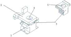
图1为本发明具有导热功能的接线端子的结构示意图。FIG. 1 is a schematic structural diagram of a connection terminal with heat conduction function according to the present invention.
具体实施方式Detailed ways
下面将结合本发明实施例中的附图,对本发明实施例中的技术方案进行清楚、完整地描述,显然,所描述的实施例仅仅是本发明一部分实施例,而不是全部的实施例。基于本发明中的实施例,本领域普通技术人员在没有做出创造性劳动前提下所获得的所有其他实施例,都属于本发明保护的范围。The following will clearly and completely describe the technical solutions in the embodiments of the present invention with reference to the accompanying drawings in the embodiments of the present invention. Obviously, the described embodiments are only some, not all, embodiments of the present invention. Based on the embodiments of the present invention, all other embodiments obtained by persons of ordinary skill in the art without making creative efforts belong to the protection scope of the present invention.
参见图1,一种具有导热功能的接线端子,用于塑壳断路器,所述接线端子包括多个端子本体和用于将多个所述端子本体电连接的联接板2,所述联接板2一端与端子本体电连接,所述联接板另一端与所述塑壳断路器内的触头电联接,如动触头或静触头电联接;Referring to Fig. 1, a connection terminal with heat conduction function is used for a molded case circuit breaker, the connection terminal includes a plurality of terminal bodies and a
所述联接板固定有散热鳍片3,所述散热鳍片3安装于所述塑壳断路器的外部,提高散热效率。The connecting plate is fixed with
联接板2的主体为铜材料,散热鳍片的材料为铝,这里散热鳍片为若干散热片的平行阵列。The main body of the connecting
所述散热鳍片3固定于所述联接板2面积最大的表面上。The
所述联接板2表面具有第一螺纹孔4,第二螺纹孔5设置于所述散热鳍片3,所述散热鳍片3与所述联接板2通过螺钉连接固定。The connecting
塑料罩1设置于所述散热鳍片3的表面,起到防止散热鳍片3受损坏的作用。The
所述塑料罩1的侧面设有散热通孔,散热通孔连通所述塑料罩1的内部和外部。The side of the
所述塑料罩1与所述散热鳍片3过盈配合,具体的,所述塑料罩1的内侧设有卡槽,所述卡槽与所述散热鳍片3卡扣配合,防止塑料罩1意外脱落。The
塑料罩为PA材料,其具有优异的电绝缘性能。The plastic cover is PA material, which has excellent electrical insulation properties.
可选的,所述散热鳍片3的材料为含铝合金,铝的比重超过50%。Optionally, the
上述接线端子,联接板的主体为铜材料,散热鳍片的材料为铝,铜的密度8.9比铝的密度2.7高3倍多,所以要将比热乘以密度来求热容,相乘之后的结果是:铜的热容是3.43J/Gv;铝的热容是2.42J/Gv,也就是说在相同体积下,铝更容易降温。For the above terminal, the main body of the connecting plate is made of copper, and the material of the cooling fins is made of aluminum. The density of copper is 8.9 which is more than three times higher than the density of aluminum of 2.7. Therefore, the heat capacity must be calculated by multiplying the specific heat by the density. The result is: the heat capacity of copper is 3.43J/Gv; the heat capacity of aluminum is 2.42J/Gv, which means that under the same volume, aluminum is easier to cool down.
本发明的联接板设有散热鳍片,联接板的主体为铜,散热鳍片为铝材料,铜的导热比铝快3倍,但是相同体积下,铝比铜的降温效率高1.5倍。所以它们就各自发挥其优势,导热更快的铜用来做底座,快速导热;降温更快的铝用来做散热器鳍片,迅速带走热量。The connection plate of the present invention is provided with heat dissipation fins, the main body of the connection plate is copper, and the heat dissipation fins are made of aluminum. The heat conduction of copper is 3 times faster than that of aluminum, but the cooling efficiency of aluminum is 1.5 times higher than that of copper under the same volume. So they give full play to their respective advantages. Copper with faster heat conduction is used as the base to conduct heat quickly; aluminum with faster cooling is used as radiator fins to quickly remove heat.
经过温度检测发现,未使用散热端子产品温升在50K~59K之间,而使用上述散热端子产品的温升在35K~47K之间。After temperature detection, it is found that the temperature rise of products without heat dissipation terminals is between 50K and 59K, while the temperature rise of products using the above heat dissipation terminals is between 35K and 47K.
最后应说明的是:以上所述仅为本发明的优选实施例而已,并不用于限制本发明,尽管参照前述实施例对本发明进行了详细的说明,对于本领域的技术人员来说,其依然可以对前述各实施例所记载的技术方案进行修改,或者对其中部分技术特征进行等同替换,凡在本发明的精神和原则之内,所作的任何修改、等同替换、改进等,均应包含在本发明的保护范围之内。Finally, it should be noted that: the above is only a preferred embodiment of the present invention, and is not intended to limit the present invention. Although the present invention has been described in detail with reference to the foregoing embodiments, for those skilled in the art, it still It is possible to modify the technical solutions recorded in the foregoing embodiments, or to perform equivalent replacements on some of the technical features. Any modifications, equivalent replacements, improvements, etc. within the spirit and principles of the present invention shall be included in the within the protection scope of the present invention.
Claims (10)
Priority Applications (1)
| Application Number | Priority Date | Filing Date | Title |
|---|---|---|---|
| CN202310000165.8ACN116092886A (en) | 2023-01-02 | 2023-01-02 | Binding post with heat conduction function |
Applications Claiming Priority (1)
| Application Number | Priority Date | Filing Date | Title |
|---|---|---|---|
| CN202310000165.8ACN116092886A (en) | 2023-01-02 | 2023-01-02 | Binding post with heat conduction function |
Publications (1)
| Publication Number | Publication Date |
|---|---|
| CN116092886Atrue CN116092886A (en) | 2023-05-09 |
Family
ID=86207671
Family Applications (1)
| Application Number | Title | Priority Date | Filing Date |
|---|---|---|---|
| CN202310000165.8APendingCN116092886A (en) | 2023-01-02 | 2023-01-02 | Binding post with heat conduction function |
Country Status (1)
| Country | Link |
|---|---|
| CN (1) | CN116092886A (en) |
Citations (5)
| Publication number | Priority date | Publication date | Assignee | Title |
|---|---|---|---|---|
| CN101281835A (en)* | 2007-04-03 | 2008-10-08 | Ls产电株式会社 | Modular terminal for moulded case circuit breaker and moulded case circuit breaker having the same |
| CN206516589U (en)* | 2017-03-03 | 2017-09-22 | 德力西电气有限公司 | A kind of moulded case circuit breaker with external series connection row |
| CN208460683U (en)* | 2018-02-11 | 2019-02-01 | 广东南冠电气有限公司 | A kind of electronic type molded case circuit breaker with residual current protecting function |
| CN212874379U (en)* | 2019-08-02 | 2021-04-02 | Abb股份公司 | Terminal clamp covering device for low-voltage circuit breaker and corresponding low-voltage circuit breaker |
| CN213042846U (en)* | 2020-09-25 | 2021-04-23 | 台安科技(无锡)有限公司 | Heat radiation structure for molded case circuit breaker |
- 2023
- 2023-01-02CNCN202310000165.8Apatent/CN116092886A/enactivePending
Patent Citations (5)
| Publication number | Priority date | Publication date | Assignee | Title |
|---|---|---|---|---|
| CN101281835A (en)* | 2007-04-03 | 2008-10-08 | Ls产电株式会社 | Modular terminal for moulded case circuit breaker and moulded case circuit breaker having the same |
| CN206516589U (en)* | 2017-03-03 | 2017-09-22 | 德力西电气有限公司 | A kind of moulded case circuit breaker with external series connection row |
| CN208460683U (en)* | 2018-02-11 | 2019-02-01 | 广东南冠电气有限公司 | A kind of electronic type molded case circuit breaker with residual current protecting function |
| CN212874379U (en)* | 2019-08-02 | 2021-04-02 | Abb股份公司 | Terminal clamp covering device for low-voltage circuit breaker and corresponding low-voltage circuit breaker |
| CN213042846U (en)* | 2020-09-25 | 2021-04-23 | 台安科技(无锡)有限公司 | Heat radiation structure for molded case circuit breaker |
Similar Documents
| Publication | Publication Date | Title |
|---|---|---|
| US8339772B2 (en) | Heat dissipation means for increasing power density in enclosed equipment | |
| US4060847A (en) | Cooling arrangement for electrical power contactor | |
| US3769551A (en) | Circuit breaker with heat pipe cooling means | |
| CN101901705A (en) | Cooling device for circuit breaker and circuit breaker including the cooling device | |
| US3764765A (en) | Heat dissipation means for electric devices mounted in switchboards (especially circuit breakers) | |
| EP1758136B1 (en) | Electrical switching apparatus and heat sink therefor | |
| KR101608685B1 (en) | Circuit breaker comprising ventilation channels for efficient heat dissipation | |
| US3879100A (en) | Circuit breaker terminal connector, and heat dissipator assembly | |
| CN120015590A (en) | Photovoltaic fuse and its accessories | |
| KR101578341B1 (en) | Switching device with a heat extraction apparatus | |
| CN116092886A (en) | Binding post with heat conduction function | |
| US3204150A (en) | Terminal connections for circuit protective devices | |
| KR20250125943A (en) | Thermal management devices for circuit breakers | |
| EP2306482B1 (en) | Main circuit terminal assembly for vacuum circuit breaker | |
| CN219144268U (en) | Temperature control assembly, high-capacity battery and energy storage system | |
| CN203312147U (en) | Vacuum circuit breaker | |
| CN116798791A (en) | Connecting row for heat dissipation of molded case circuit breaker and heat dissipation structure of molded case circuit breaker | |
| CN104303368B (en) | Pole connectors for series circuit breakers | |
| CN221226134U (en) | Temperature rise control wiring terminal for molded case circuit breaker | |
| CN219180423U (en) | Assembled heavy current circuit breaker utmost point post with heat dissipation function | |
| US20250120049A1 (en) | Heat sink for a solid-state circuit breaker in an electrical panel | |
| US12213287B2 (en) | Heat sink for a solid-state circuit breakerin an electrical panel | |
| CN113193506B (en) | Compartment for medium voltage air or gas insulated switchgear | |
| CN211352830U (en) | High-voltage power distribution module | |
| US9444230B2 (en) | Power distribution assembly and header assembly therefor |
Legal Events
| Date | Code | Title | Description |
|---|---|---|---|
| PB01 | Publication | ||
| PB01 | Publication | ||
| SE01 | Entry into force of request for substantive examination | ||
| SE01 | Entry into force of request for substantive examination |