CN116080260A - Digital printing system and method - Google Patents
Digital printing system and methodDownload PDFInfo
- Publication number
- CN116080260A CN116080260ACN202310285782.7ACN202310285782ACN116080260ACN 116080260 ACN116080260 ACN 116080260ACN 202310285782 ACN202310285782 ACN 202310285782ACN 116080260 ACN116080260 ACN 116080260A
- Authority
- CN
- China
- Prior art keywords
- target substrate
- image
- processor
- itm
- light
- Prior art date
- Legal status (The legal status is an assumption and is not a legal conclusion. Google has not performed a legal analysis and makes no representation as to the accuracy of the status listed.)
- Pending
Links
Images


Classifications
- B—PERFORMING OPERATIONS; TRANSPORTING
- B41—PRINTING; LINING MACHINES; TYPEWRITERS; STAMPS
- B41F—PRINTING MACHINES OR PRESSES
- B41F16/00—Transfer printing apparatus
- B—PERFORMING OPERATIONS; TRANSPORTING
- B41—PRINTING; LINING MACHINES; TYPEWRITERS; STAMPS
- B41J—TYPEWRITERS; SELECTIVE PRINTING MECHANISMS, i.e. MECHANISMS PRINTING OTHERWISE THAN FROM A FORME; CORRECTION OF TYPOGRAPHICAL ERRORS
- B41J2/00—Typewriters or selective printing mechanisms characterised by the printing or marking process for which they are designed
- B41J2/005—Typewriters or selective printing mechanisms characterised by the printing or marking process for which they are designed characterised by bringing liquid or particles selectively into contact with a printing material
- B41J2/0057—Typewriters or selective printing mechanisms characterised by the printing or marking process for which they are designed characterised by bringing liquid or particles selectively into contact with a printing material where an intermediate transfer member receives the ink before transferring it on the printing material
- G—PHYSICS
- G03—PHOTOGRAPHY; CINEMATOGRAPHY; ANALOGOUS TECHNIQUES USING WAVES OTHER THAN OPTICAL WAVES; ELECTROGRAPHY; HOLOGRAPHY
- G03G—ELECTROGRAPHY; ELECTROPHOTOGRAPHY; MAGNETOGRAPHY
- G03G15/00—Apparatus for electrographic processes using a charge pattern
- G03G15/14—Apparatus for electrographic processes using a charge pattern for transferring a pattern to a second base
- G03G15/16—Apparatus for electrographic processes using a charge pattern for transferring a pattern to a second base of a toner pattern, e.g. a powder pattern, e.g. magnetic transfer
- G03G15/1605—Apparatus for electrographic processes using a charge pattern for transferring a pattern to a second base of a toner pattern, e.g. a powder pattern, e.g. magnetic transfer using at least one intermediate support
- G03G15/1615—Apparatus for electrographic processes using a charge pattern for transferring a pattern to a second base of a toner pattern, e.g. a powder pattern, e.g. magnetic transfer using at least one intermediate support relating to the driving mechanism for the intermediate support, e.g. gears, couplings, belt tensioning
- B—PERFORMING OPERATIONS; TRANSPORTING
- B41—PRINTING; LINING MACHINES; TYPEWRITERS; STAMPS
- B41F—PRINTING MACHINES OR PRESSES
- B41F33/00—Indicating, counting, warning, control or safety devices
- B41F33/0036—Devices for scanning or checking the printed matter for quality control
- B—PERFORMING OPERATIONS; TRANSPORTING
- B41—PRINTING; LINING MACHINES; TYPEWRITERS; STAMPS
- B41J—TYPEWRITERS; SELECTIVE PRINTING MECHANISMS, i.e. MECHANISMS PRINTING OTHERWISE THAN FROM A FORME; CORRECTION OF TYPOGRAPHICAL ERRORS
- B41J11/00—Devices or arrangements of selective printing mechanisms, e.g. ink-jet printers or thermal printers, for supporting or handling copy material in sheet or web form
- B41J11/0015—Devices or arrangements of selective printing mechanisms, e.g. ink-jet printers or thermal printers, for supporting or handling copy material in sheet or web form for treating before, during or after printing or for uniform coating or laminating the copy material before or after printing
- B41J11/002—Curing or drying the ink on the copy materials, e.g. by heating or irradiating
- B41J11/0021—Curing or drying the ink on the copy materials, e.g. by heating or irradiating using irradiation
- B41J11/00216—Curing or drying the ink on the copy materials, e.g. by heating or irradiating using irradiation using infrared [IR] radiation or microwaves
- B—PERFORMING OPERATIONS; TRANSPORTING
- B41—PRINTING; LINING MACHINES; TYPEWRITERS; STAMPS
- B41J—TYPEWRITERS; SELECTIVE PRINTING MECHANISMS, i.e. MECHANISMS PRINTING OTHERWISE THAN FROM A FORME; CORRECTION OF TYPOGRAPHICAL ERRORS
- B41J2/00—Typewriters or selective printing mechanisms characterised by the printing or marking process for which they are designed
- B41J2/005—Typewriters or selective printing mechanisms characterised by the printing or marking process for which they are designed characterised by bringing liquid or particles selectively into contact with a printing material
- B41J2/01—Ink jet
- G—PHYSICS
- G03—PHOTOGRAPHY; CINEMATOGRAPHY; ANALOGOUS TECHNIQUES USING WAVES OTHER THAN OPTICAL WAVES; ELECTROGRAPHY; HOLOGRAPHY
- G03G—ELECTROGRAPHY; ELECTROPHOTOGRAPHY; MAGNETOGRAPHY
- G03G15/00—Apparatus for electrographic processes using a charge pattern
- G03G15/06—Apparatus for electrographic processes using a charge pattern for developing
- G03G15/10—Apparatus for electrographic processes using a charge pattern for developing using a liquid developer
- G—PHYSICS
- G03—PHOTOGRAPHY; CINEMATOGRAPHY; ANALOGOUS TECHNIQUES USING WAVES OTHER THAN OPTICAL WAVES; ELECTROGRAPHY; HOLOGRAPHY
- G03G—ELECTROGRAPHY; ELECTROPHOTOGRAPHY; MAGNETOGRAPHY
- G03G15/00—Apparatus for electrographic processes using a charge pattern
- G03G15/50—Machine control of apparatus for electrographic processes using a charge pattern, e.g. regulating differents parts of the machine, multimode copiers, microprocessor control
- B—PERFORMING OPERATIONS; TRANSPORTING
- B41—PRINTING; LINING MACHINES; TYPEWRITERS; STAMPS
- B41J—TYPEWRITERS; SELECTIVE PRINTING MECHANISMS, i.e. MECHANISMS PRINTING OTHERWISE THAN FROM A FORME; CORRECTION OF TYPOGRAPHICAL ERRORS
- B41J2/00—Typewriters or selective printing mechanisms characterised by the printing or marking process for which they are designed
- B41J2/005—Typewriters or selective printing mechanisms characterised by the printing or marking process for which they are designed characterised by bringing liquid or particles selectively into contact with a printing material
- B41J2/01—Ink jet
- B41J2002/012—Ink jet with intermediate transfer member
- B—PERFORMING OPERATIONS; TRANSPORTING
- B41—PRINTING; LINING MACHINES; TYPEWRITERS; STAMPS
- B41M—PRINTING, DUPLICATING, MARKING, OR COPYING PROCESSES; COLOUR PRINTING
- B41M5/00—Duplicating or marking methods; Sheet materials for use therein
- B41M5/025—Duplicating or marking methods; Sheet materials for use therein by transferring ink from the master sheet
- B41M5/0256—Duplicating or marking methods; Sheet materials for use therein by transferring ink from the master sheet the transferable ink pattern being obtained by means of a computer driven printer, e.g. an ink jet or laser printer, or by electrographic means
- G—PHYSICS
- G03—PHOTOGRAPHY; CINEMATOGRAPHY; ANALOGOUS TECHNIQUES USING WAVES OTHER THAN OPTICAL WAVES; ELECTROGRAPHY; HOLOGRAPHY
- G03G—ELECTROGRAPHY; ELECTROPHOTOGRAPHY; MAGNETOGRAPHY
- G03G2215/00—Apparatus for electrophotographic processes
- G03G2215/00362—Apparatus for electrophotographic processes relating to the copy medium handling
- G03G2215/00919—Special copy medium handling apparatus
- G03G2215/00949—Copy material feeding speed switched according to current mode of the apparatus, e.g. colour mode
Landscapes
- Engineering & Computer Science (AREA)
- Physics & Mathematics (AREA)
- General Physics & Mathematics (AREA)
- Health & Medical Sciences (AREA)
- General Health & Medical Sciences (AREA)
- Toxicology (AREA)
- Mechanical Engineering (AREA)
- Quality & Reliability (AREA)
- Microelectronics & Electronic Packaging (AREA)
- Ink Jet (AREA)
- Printing Methods (AREA)
- Accessory Devices And Overall Control Thereof (AREA)
Abstract
Translated fromChinese
Description
Translated fromChinese本申请为国际申请号为PCT/IB2019/061081,国际申请日为2019年12月19日,发明名称为“数字印刷系统和方法”的PCT申请于2021年06月23日进入中国国家阶段后申请号为201980085646.5的中国国家阶段专利申请的分案申请。This application is the PCT application with the international application number PCT/IB2019/061081, the international application date is December 19, 2019, and the PCT application titled "Digital Printing System and Method" was filed after entering the Chinese national phase on June 23, 2021 Divisional application of Chinese national phase patent application No. 201980085646.5.
相关申请的交叉引用Cross References to Related Applications
本申请要求在2018年12月24日提交的美国临时专利申请62/784,576和在2018年12月24日提交的美国临时专利申请62/784,579的权益,所述申请的公开内容全部以引用的方式并入本文。This application claims the benefit of U.S.
技术领域technical field
本发明总体涉及数字印刷,并且具体地,涉及用于在连续基片上进行数字印刷的方法和系统。The present invention relates generally to digital printing, and in particular, to methods and systems for digital printing on continuous substrates.
背景技术Background technique
在各种应用中,诸如在生产标签和塑料袋的过程中,需要将图像印刷在合适的连续介质上。另外,已经开发了用于监测数字印刷中的失真(且具体地,几何失真)的各种方法。In various applications, such as in the production of labels and plastic bags, images need to be printed on suitable continuous media. Additionally, various methods for monitoring distortion (and in particular geometric distortion) in digital printing have been developed.
例如,美国专利申请公布2002/0149771描述了一种检验装置,所述检验装置包括分别将检验光和辅助光投影到胶卷的位置上的检验光投影仪和辅助光发射器。在透射了胶卷之后,由缺陷检测器接收检验光。在接收到检验光时,缺陷检测器生成数据信号并且将所述数据信号发送至控制器。在控制器中,记住数据信号的电平的阈值,并且将数据信号的电平与所述阈值进行比较。如果数据信号的电平在所述阈值之下,则控制器确定胶卷具有着色缺陷。For example, US Patent Application Publication 2002/0149771 describes an inspection device that includes an inspection light projector and an auxiliary light emitter that respectively project inspection light and auxiliary light onto a film position. After transmission of the film, inspection light is received by a defect detector. Upon receiving the inspection light, the defect detector generates a data signal and sends the data signal to the controller. In the controller, a threshold value for the level of the data signal is memorized, and the level of the data signal is compared with said threshold value. If the level of the data signal is below the threshold, the controller determines that the film has a tinting defect.
美国专利申请公布2010/0165333描述了一种用于检验层压膜的方法和装置。所述方法包括第一检验过程:检验具有与膜主体分离的保护膜的所述膜主体的前表面上的缺陷的存在。所述方法还包括第二检验过程:在将分离了分离器并且从膜主体移除了分离器的膜主体引入至在竖直方向上引导的膜行进路径时检验呈竖直姿势的膜主体中的缺陷的存在,并且存储检测数据。US Patent Application Publication 2010/0165333 describes a method and apparatus for inspecting laminated films. The method includes a first inspection process of inspecting the presence of a defect on a front surface of the film body having a protective film separated from the film body. The method also includes a second inspection process of inspecting the membrane body in a vertical posture when the membrane body with the separator separated and removed from the membrane body is introduced into a membrane travel path guided in a vertical direction the presence of defects, and store inspection data.
美国专利5,969,372描述了用于在光学图像扫描仪中检测透射性图像上的表面缺陷和伪影并且校正所得的扫描图像的方法和设备。在一次扫描中,图像被正常扫描。表面缺陷和伪影,诸如灰尘、划擦和指纹,是通过以下操作来检测:使用红外光来提供单独扫描;或测量被缺陷和伪影散射或衍射的光(白色或红外)。US Patent 5,969,372 describes a method and apparatus for detecting surface defects and artifacts on a transmission image in an optical image scanner and correcting the resulting scanned image. In one scan, the image is scanned normally. Surface defects and artifacts, such as dust, scratches and fingerprints, are detected by using infrared light to provide individual scans; or measuring light (white or infrared) scattered or diffracted by defects and artifacts.
发明内容Contents of the invention
本文描述的本发明的实施方案提供一种数字印刷系统,所述数字印刷系统包括:中间转印构件(ITM),所述中间转印构件被配置为接收印刷流体以便形成图像;连续目标基片;以及处理器。所述连续目标基片被配置为在接合点处与ITM接合以便从所述ITM接收图像,在所述接合点处,所述ITM被配置为以第一速度移动,并且所述连续目标基片被配置为以第二速度移动。所述处理器被配置为在所述接合点处使所述第一速度和所述第二速度匹配。Embodiments of the invention described herein provide a digital printing system comprising: an intermediate transfer member (ITM) configured to receive printing fluid to form an image; a continuous target substrate ; and the processor. The continuous target substrate is configured to engage an ITM at a junction point where the ITM is configured to move at a first speed and the continuous target substrate Configured to move at a second speed. The processor is configured to match the first speed and the second speed at the engagement point.
在一些实施方案中,所述印刷流体包括从油墨供应系统接收的墨滴以在上面形成图像。在其他实施方案中,所述系统包括第一鼓和第二鼓,所述第一鼓被配置为以第一方向和第一旋转速度旋转以便使ITM以所述第一速度移动,并且所述第二鼓被配置为以第二方向和第二旋转速度旋转以便使连续目标基片以所述第二速度移动,并且所述处理器被配置为通过移位所述第一鼓和所述第二鼓中的一者或两者而在接合点处使ITM与连续目标基片之间接合和脱离。在其他实施方案中,所述处理器被配置为接收指示在所述第一速度与所述第二速度之间的差的电信号,并且基于所述电信号而使所述第一速度和所述第二速度匹配。In some embodiments, the printing fluid includes ink drops received from an ink supply system to form an image thereon. In other embodiments, the system includes a first drum and a second drum, the first drum is configured to rotate in a first direction and a first rotational speed to move the ITM at the first speed, and the The second drum is configured to rotate in a second direction and a second rotational speed so as to move successive target substrates at the second speed, and the processor is configured to One or both of the drums engage and disengage the ITM from the continuous target substrate at the splice point. In other embodiments, the processor is configured to receive an electrical signal indicative of a difference between the first speed and the second speed, and to set the first speed and the second speed based on the electrical signal. The second speed matching described above.
在一个实施方案中,所述处理器被配置为设置选自由以下各项组成的列表的至少一个操作:(a)在所述第一鼓与所述第二鼓之间的接合和脱离的时序;(b)所述第一鼓和所述第二鼓中的至少一者的运动曲线;以及(c)在脱离的所述第一鼓与所述第二鼓之间的间隙的大小。在另一实施方案中,所述系统包括电动马达,所述电动马达被配置为移动ITM和目标基片中的一者或两者,所述处理器被配置为接收指示流过所述电动马达的电流上的时间变化的信号,并且响应于所述信号而使所述第一速度和所述第二速度匹配。在另一实施方案中,所述处理器被配置为通过减小电流上的时间变化而使所述第一速度和所述第二速度匹配。In one embodiment, said processor is configured to set at least one operation selected from the list consisting of: (a) the timing of engagement and disengagement between said first drum and said second drum ; (b) a motion profile of at least one of the first drum and the second drum; and (c) a size of a gap between the disengaged first drum and the second drum. In another embodiment, the system includes an electric motor configured to move one or both of the ITM and the target substrate, the processor configured to receive instructions flowing through the electric motor and matching the first speed and the second speed in response to the signal. In another embodiment, the processor is configured to match the first speed and the second speed by reducing temporal variation in current.
在一些实施方案中,所述时间变化包括在预先限定的时间间隔内的电流随时间的斜率。在其他实施方案中,所述处理器被配置为通过减小电流上的时间变化而补偿所述第一鼓和所述第二鼓中的至少一者的热膨胀。在其他实施方案中,所述连续目标基片包括具有第一厚度的第一基片或具有不同于所述第一厚度的第二厚度的第二基片,并且所述处理器被配置为通过减小电流上的时间变化而补偿在所述第一厚度与所述第二厚度之间的差异。In some embodiments, the temporal variation comprises a slope of the current over time over a predefined time interval. In other embodiments, the processor is configured to compensate for thermal expansion of at least one of the first drum and the second drum by reducing temporal variation in electrical current. In other embodiments, the continuous target substrate comprises a first substrate having a first thickness or a second substrate having a second thickness different from the first thickness, and the processor is configured to pass A temporal variation in current is reduced to compensate for a difference between the first thickness and the second thickness.
在一个实施方案中,ITM是由通过接缝区段闭合的环路形成,并且所述处理器被配置为通过以下操作防止在所述接缝区段与所述连续目标基片之间的物理接触:(a)在所述接缝区段横越接合点的时间间隔期间导致在ITM与连续目标基片之间的暂时脱离;以及(b)在所述时间间隔期间使所述连续目标基片反向回退,以便补偿所述暂时脱离。在另一实施方案中,所述系统包括反向回退机构,所述反向回退机构被配置为使连续目标基片反向回退,并且至少包括与所述连续目标基片具有物理接触的第一可移位辊和第二可移位辊,并且被配置为通过使所述辊相对于彼此移动而使所述连续目标基片反向回退。在另一实施方案中,所述ITM包括多个层的堆叠,并且具有在沿着所述ITM的一个或多个相应的标记位置处在所述层中的至少一者中雕刻的一个或多个标记。In one embodiment, the ITM is formed by a loop closed by a seam segment, and the processor is configured to prevent physical contact between the seam segment and the continuous target substrate by contacting: (a) causing a temporary disengagement between the ITM and the continuous target substrate during the time interval during which the seam segment traverses the joint; and (b) causing the continuous target substrate to disengage during the time interval. Back off in reverse in order to compensate for the temporary disengagement. In another embodiment, the system includes a reverse retraction mechanism configured to reversely retract a continuous target substrate and includes at least physical contact with the continuous target substrate The first displaceable roller and the second displaceable roller are configured to reversely retract the continuous target substrate by moving the rollers relative to each other. In another embodiment, the ITM comprises a stack of layers and has one or more engraved in at least one of the layers at one or more corresponding marking locations along the ITM. tags.
在一些实施方案中,所述系统包括一个或多个感测组件,所述一个或多个感测组件设置在相对于ITM的一个或多个相应的预先限定的位置处,所述感测组件被配置为产生指示所述标记的相应位置的信号。在其他实施方案中,处理器被配置为接收信号,并且基于所述信号而控制墨滴在ITM上的沉积。在其他实施方案中,所述系统包括至少一个站或组件,所述处理器被配置为基于所述信号而控制所述系统的所述至少一个站或组件的操作。In some embodiments, the system includes one or more sensing components disposed at one or more respective predefined positions relative to the ITM, the sensing components configured to generate a signal indicative of a corresponding position of the marker. In other embodiments, the processor is configured to receive a signal and to control deposition of ink drops on the ITM based on the signal. In other embodiments, the system includes at least one station or component, the processor configured to control operation of the at least one station or component of the system based on the signal.
在一个实施方案中,所述至少一个站或组件选自由以下各项组成的列表:(a)图像形成站;(b)压印站;(c)ITM导引系统;(d)一个或多个烘干组件;(e)ITM处理站;以及(f)图像质量控制站。在另一实施方案中,所述系统包括图像形成模块,所述图像形成模块被配置为向ITM施加物质。In one embodiment, said at least one station or component is selected from the list consisting of: (a) an image forming station; (b) an embossing station; (c) an ITM guidance system; (d) one or more a drying assembly; (e) an ITM processing station; and (f) an image quality control station. In another embodiment, the system includes an image forming module configured to apply a substance to the ITM.
在一些实施方案中,所述物质包括印刷流体的至少一部分。在其他实施方案中,所述图像形成模块包括轮转凹版印刷设备。In some embodiments, the substance includes at least a portion of the printing fluid. In other embodiments, the image forming module comprises a rotogravure printing device.
根据本发明的实施方案,另外提供了一种方法,所述方法包括在中间转印构件(ITM)上接收印刷流体以便形成图像。使连续目标基片在接合点处与ITM接合以便从ITM接收图像,并且在所述接合点处,使ITM以第一速度移动并且使连续目标基片以第二速度移动。在所述接合点处使所述第一速度和所述第二速度匹配。According to an embodiment of the present invention, there is additionally provided a method comprising receiving a printing fluid on an intermediate transfer member (ITM) to form an image. The continuous target substrate is joined to the ITM at a joint point to receive an image from the ITM, and at the joint point, the ITM is moved at a first speed and the continuous target substrate is moved at a second speed. The first speed and the second speed are matched at the engagement point.
根据本发明的实施方案,还提供了一种数字印刷系统,所述数字印刷系统包括中间转印构件(ITM)、光源、图像传感器组件和处理器。所述ITM被配置为接收印刷流体以便形成图像,并且与具有相对的第一表面和第二表面的目标基片接合,以便将图像转印到所述目标基片。光源被配置为使用光照射目标基片的第一表面。图像传感器组件被配置为将通过目标基片传输的光的至少一部分成像到第二表面,并且响应于成像的光而产生电信号。处理器被配置为基于电信号而产生数字图像,并且基于数字图像而估计印刷出的图像中的至少失真。According to an embodiment of the present invention, there is also provided a digital printing system including an intermediate transfer member (ITM), a light source, an image sensor assembly, and a processor. The ITM is configured to receive a printing fluid to form an image, and to engage a target substrate having opposing first and second surfaces to transfer the image to the target substrate. The light source is configured to illuminate the first surface of the target substrate with light. The image sensor assembly is configured to image at least a portion of the light transmitted through the target substrate onto the second surface and generate an electrical signal in response to the imaged light. The processor is configured to generate a digital image based on the electrical signal, and to estimate at least distortion in the printed image based on the digital image.
在一些实施方案中,目标基片包括连续目标基片。在其他实施方案中,失真包括几何失真。在其他实施方案中,处理器被配置为通过分析目标基片上的一个或多个标记来估计失真。In some embodiments, the target substrate comprises a continuous target substrate. In other embodiments, the distortion includes geometric distortion. In other embodiments, the processor is configured to estimate distortion by analyzing one or more marks on the target substrate.
在一个实施方案中,所述标记中的至少一者包括条形码。在另一实施方案中,光源包括光漫射器。在另一实施方案中,光源至少包括发光二极管(LED)。在另一实施方案中,所述系统包括一个或多个运动组件,所述一个或多个运动组件被配置为使目标基片和图像传感器组件中的至少一者相对于彼此移动,处理器被配置为通过控制所述一个或多个运动组件而产生数字图像。In one embodiment, at least one of said indicia comprises a barcode. In another embodiment, the light source includes a light diffuser. In another embodiment, the light source comprises at least a light emitting diode (LED). In another embodiment, the system includes one or more motion assemblies configured to move at least one of the target substrate and the image sensor assembly relative to each other, the processor being controlled by configured to generate a digital image by controlling the one or more motion components.
在一些实施方案中,处理器被配置为使用一个或多个运动组件中的至少一者以便在光源与图像传感器组件之间定位形成于目标基片上的标记。在其他实施方案中,运动组件包括第一运动组件和第二运动组件,并且处理器被配置为(i)每次使第一运动组件和第二运动组件中的仅一者移动,以及(ii)使第一运动组件和第二运动组件同时移动。在其他实施方案中,处理器被配置为在产生印刷出的图像期间至少估计图像中的失真。In some embodiments, the processor is configured to use at least one of the one or more motion assemblies to position the indicia formed on the target substrate between the light source and the image sensor assembly. In other embodiments, the motion assembly includes a first motion assembly and a second motion assembly, and the processor is configured to (i) move only one of the first motion assembly and the second motion assembly at a time, and (ii ) causes the first kinematic component and the second kinematic component to move simultaneously. In other embodiments, the processor is configured to at least estimate distortion in the image during generation of the printed image.
在一个实施方案中,处理器被配置为通过分析穿过目标基片透射到第二表面的光的强度来估计印刷流体的至少密度。在另一实施方案中,印刷流体包括白色油墨。在另一实施方案中,电信号指示强度,并且处理器被配置为在数字图像中产生指示强度的灰度。In one embodiment, the processor is configured to estimate at least the density of the printing fluid by analyzing the intensity of light transmitted through the target substrate to the second surface. In another embodiment, the printing fluid includes white ink. In another embodiment, the electrical signal is indicative of intensity, and the processor is configured to generate gray scales indicative of intensity in the digital image.
根据本发明的实施方案,另外提供了一种方法,所述方法包括:在数字印刷系统中由中间转印构件(ITM)接收印刷流体以便形成图像,并且与具有相对的第一表面和第二表面的目标基片接合以便将图像转印到目标基片。使用光源利用光照射目标基片的第一表面。使用图像传感器组件将穿过目标基片透射的光的至少一部分成像到第二表面,并且响应于成像的光而产生电信号。基于电信号而产生数字图像,并且基于数字图像而估计印刷出的图像中的至少失真。According to an embodiment of the present invention, there is additionally provided a method comprising: receiving a printing fluid by an intermediate transfer member (ITM) in a digital printing system to form an image, and having opposing first surfaces and second The target substrate of the surface is bonded to transfer the image to the target substrate. A light source is used to illuminate the first surface of the target substrate with light. At least a portion of the light transmitted through the target substrate is imaged onto the second surface using an image sensor assembly, and an electrical signal is generated in response to the imaged light. A digital image is generated based on the electrical signal, and at least distortion in the printed image is estimated based on the digital image.
通过与附图一起进行的对本发明的实施方案的以下详细描述,将更全面地理解本发明,附图中:The invention will be more fully understood from the following detailed description of embodiments of the invention taken in conjunction with the accompanying drawings, in which:
附图说明Description of drawings
图1A是根据本发明的实施方案的数字印刷系统的示意性侧视图;Figure 1A is a schematic side view of a digital printing system according to an embodiment of the present invention;
图1B是根据本发明的实施方案的基片运输模块的示意性侧视图;Figure IB is a schematic side view of a substrate transport module according to an embodiment of the present invention;
图2是根据本发明的实施方案的反向回退模块的示意性侧视图;Figure 2 is a schematic side view of a reverse fallback module according to an embodiment of the present invention;
图3是根据本发明的实施方案的用于控制基片运输模块的曲线图的示意性立体说明图;3 is a schematic perspective illustration of a graph for controlling a substrate transport module according to an embodiment of the present invention;
图4是根据本发明的实施方案的数字印刷系统的压印站的示意性侧视图;以及Figure 4 is a schematic side view of an embossing station of a digital printing system according to an embodiment of the present invention; and
图5是根据本发明的实施方案的作为数字印刷系统的部分的图像形成站和多个烘干站的示意性侧视图;5 is a schematic side view of an image forming station and a plurality of drying stations as part of a digital printing system according to an embodiment of the present invention;
图6是根据本发明的实施方案的集成到数字印刷系统中的检验模块的示意性侧视图;以及6 is a schematic side view of an inspection module integrated into a digital printing system according to an embodiment of the present invention; and
图7是根据本发明的实施方案的示意性地说明用于监测连续网状物基片上的数字印刷中产生的缺陷的方法的流程图。Figure 7 is a flow chart schematically illustrating a method for monitoring defects produced in digital printing on a continuous web substrate, according to an embodiment of the present invention.
具体实施方式Detailed ways
概述overview
在下文描述的本发明的实施方案提供了用于在连续基片上进行数字印刷的方法和设备。在一些实施方案中,一种数字印刷系统包括:柔性中间转印构件(ITM),所述柔性中间转印构件被配置为接收通过将诸如含水油墨的印刷流体铺放在ITM上而形成的图像;以及目标基片,所述目标基片被配置为在接合点处与ITM接合以用于从所述ITM接收图像。在接合点处,分别使ITM和基片以第一速度和第二速度移动,Embodiments of the invention described below provide methods and apparatus for digital printing on continuous substrates. In some embodiments, a digital printing system includes: a flexible intermediate transfer member (ITM) configured to receive an image formed by depositing a printing fluid, such as an aqueous ink, on the ITM and a target substrate configured to be bonded to the ITM at a bonding point for receiving an image from the ITM. at the junction, moving the ITM and the substrate at a first speed and a second speed, respectively,
在一些实施方案中,所述数字印刷系统还包括压印站,所述压印站包括:压印滚筒,所述压印滚筒被配置为使目标基片以所述第一速度移动;以及压力滚筒,所述压力滚筒被配置为使ITM以所述第二速度移动。In some embodiments, the digital printing system further includes an embossing station comprising: an embossing cylinder configured to move the target substrate at the first speed; and a pressure a roller, the pressure roller configured to move the ITM at the second speed.
在一些实施方案中,所述数字印刷系统还包括处理器,所述处理器被配置为通过至少移位压印滚筒而在接合点处使ITM与基片之间接合和脱离,并且在接合点处使所述第一速度和所述第二速度匹配以便将来自ITM的油墨转印到基片。In some embodiments, the digital printing system further includes a processor configured to engage and disengage the ITM from the substrate at the engagement point by displacing at least the impression cylinder, and at the engagement point matching the first speed and the second speed to transfer the ink from the ITM to the substrate.
在一些实施方案中,ITM是由通过接缝区段闭合的环路形成,并且所述处理器被配置为通过以下操作防止在所述接缝区段与所述基片之间的非所要的物理接触:(a)在所述接缝区段横越接合点的时间间隔期间导致在ITM与连续目标基片之间的暂时脱离;以及(b)在这些时间间隔期间使所述连续目标基片反向回退,以便补偿所述暂时脱离。In some embodiments, the ITM is formed by a loop closed by a seam segment, and the processor is configured to prevent unwanted contact between the seam segment and the substrate by Physical contact: (a) causes a temporary disengagement between the ITM and the continuous target substrate during the time intervals during which the seam section traverses the joint; and (b) causes the continuous target substrate to disengage during these time intervals. Back off in reverse in order to compensate for the temporary disengagement.
在一些实施方案中,所述数字印刷系统包括电动马达,所述电动马达被配置为使ITM和目标基片中的一者或以上两者移动。在这些实施方案中,处理器被配置为接收指示流过电动马达的电流上的时间变化的信号,并且基于所述信号例如通过减小电流上的时间变化而使所述第一速度和所述第二速度匹配。In some embodiments, the digital printing system includes an electric motor configured to move one or both of the ITM and the target substrate. In these embodiments, the processor is configured to receive a signal indicative of a time change in current through the electric motor, and to increase the first speed and the Second speed match.
在一些情况下,印刷系统和/或印刷过程可具有例如由压印站的一个或多个滚筒的热膨胀或由基片的厚度变化导致的变化。在一些实施方案中,基于前述所接收的信号,处理器被配置为通过减小流过电动马达的电流上的时间变化来补偿此类(和其他)变化。In some cases, the printing system and/or printing process may have variations caused, for example, by thermal expansion of one or more cylinders of an embossing station or by changes in the thickness of the substrate. In some embodiments, based on the aforementioned received signals, the processor is configured to compensate for such (and other) variations by reducing temporal variations in current flowing through the electric motor.
所公开的技术通过补偿各种各样的系统和过程变化而提高了连续基片上的数字印刷的准确度、质量和生产率。另外,所公开的技术通过以下操作减少了对基片不动产的可能的浪费:防止接缝与基片之间的物理接触;以及使连续基片反向回退以便最小化在相邻的印刷出的图像之间的空白。The disclosed technology improves the accuracy, quality, and productivity of digital printing on continuous substrates by compensating for a wide variety of system and process variations. In addition, the disclosed technique reduces possible waste of substrate real estate by: preventing physical contact between the seam and the substrate; space between the images.
在柔性包装的各种应用中(诸如在食品包装、塑料袋和管子中)使用呈连续网的形式的基于聚合物的基片。在一些情况下,在此类基片上印刷图像的过程可导致印刷出的图像中的失真,诸如几何失真和其他缺陷。原则上,可例如使用基于反射的光学检验方法来检测此类失真。然而,向其施加的基片的高反射率以及其他噪声源(诸如基片中的皱褶)可能会干扰基础的失真指示性检验信号,并且降低检测速率和准确度。例如,基片的高反射率可导致在由光学检验设备获取的图像的视野(FOV)上的非均匀的对比度和局部饱和度,这可能会降低对所关注的缺陷的检测速率。Polymer-based substrates in the form of continuous webs are used in various applications in flexible packaging, such as in food packaging, plastic bags and tubing. In some cases, the process of printing images on such substrates can result in distortions, such as geometric distortion and other defects, in the printed images. In principle, such distortions can be detected, for example, using reflection-based optical inspection methods. However, the high reflectivity of the substrate to which it is applied, as well as other sources of noise such as wrinkles in the substrate, may interfere with the underlying distortion-indicative inspection signal and reduce detection rate and accuracy. For example, high reflectivity of the substrate can lead to non-uniform contrast and localized saturation across the field of view (FOV) of images acquired by optical inspection equipment, which can reduce the detection rate of defects of interest.
本发明的其他实施方案提供了用于检测连续基片上的数字印刷中的缺陷(诸如几何失真)的方法和系统。在这些实施方案中的一些实施方案中,所述数字印刷系统包括ITM,所述ITM被配置为接收通过将诸如前述含水油墨的印刷流体铺放在ITM上而形成的图像。数字印刷系统将图像印刷在具有相对的上表面和下表面的连续目标基片上。目标基片被配置为与ITM接合以用于从ITM接收图像。印刷在目标基片上的图像通常包括由白色油墨制成的基础层,以及使用一种或多种其他色彩的油墨在基础层上印刷的图案。Other embodiments of the invention provide methods and systems for detecting defects, such as geometric distortion, in digital printing on continuous substrates. In some of these embodiments, the digital printing system includes an ITM configured to receive an image formed by depositing a printing fluid, such as the aforementioned aqueous ink, on the ITM. Digital printing systems print images on a continuous target substrate having opposing upper and lower surfaces. The target substrate is configured to interface with the ITM for receiving an image from the ITM. The image printed on the target substrate typically includes a base layer made of white ink, and a pattern printed on the base layer using one or more other colored inks.
在一些实施方案中,印刷在目标上的图像经受检验以便检测缺陷。为了执行缺陷检测,数字印刷系统还包括光源,所述光源被配置为使用合适的光束照射目标基片的一个表面(例如,下表面)。数字印刷系统还包括图像传感器组件,所述图像传感器组件被配置为感测穿过目标基片透射到相对的表面(例如,上表面)的光束,并且响应于感测到的光而产生电信号。在一些实施方案中,图像传感器组件被配置为检测穿过目标基片、基础层和油墨图案的所透射的光的强度。例如,由于白色油墨对所发射的光是部分透明的,所以检测到的光的强度以及因此还有由图像传感器组件产生的电信号取决于白色油墨层的密度和/或厚度。In some embodiments, the image printed on the target is inspected to detect defects. To perform defect detection, the digital printing system also includes a light source configured to illuminate a surface (eg, the lower surface) of the target substrate with a suitable light beam. The digital printing system also includes an image sensor assembly configured to sense light beams transmitted through the target substrate to an opposing surface (e.g., an upper surface) and generate an electrical signal in response to the sensed light . In some embodiments, the image sensor assembly is configured to detect the intensity of light transmitted through the target substrate, base layer, and ink pattern. For example, since the white ink is partially transparent to the emitted light, the intensity of the detected light and thus also the electrical signal generated by the image sensor assembly depends on the density and/or thickness of the white ink layer.
在一些实施方案中,数字印刷系统的处理器被配置为基于从图像传感器组件接收的电信号而产生数字图像。例如,处理器被配置为产生数字彩色图像,所述数字彩色图像在数字图像的不同位置处具有每种色彩的类似或不同的色调。In some embodiments, the processor of the digital printing system is configured to generate a digital image based on electrical signals received from the image sensor assembly. For example, the processor is configured to generate a digital color image having similar or different shades of each color at different locations in the digital image.
在一些实施方案中,图像传感器组件包括具有红色、绿色和蓝色(RGB)通道的彩色相机。在本公开的背景下并且在权利要求中,术语彩色图像中的“灰度”是指指示数字图像的色彩的亮度水平的尺度。在具有RGB通道的相机中,每个通道具有一定尺度的灰度。例如,在包括具有100和200的相应灰度的两个区域的绿色通道的图像中,具有灰度200的区域将具有比具有灰度100的区域更亮的绿色色彩。In some embodiments, the image sensor assembly includes a color camera with red, green, and blue (RGB) channels. In the context of this disclosure and in the claims, the term "grayscale" in color images refers to a scale indicating the brightness level of the colors of a digital image. In a camera with RGB channels, each channel has a certain scale of grayscale. For example, in an image with a green channel that includes two regions with respective grayscales of 100 and 200, the region with
在替代性实施方案中,图像传感器组件可包括仅具有黑色、白色和灰色色彩的单色相机。在这些实施方案中,术语“灰度”表示指示仅在黑与白之间的亮度水平的尺度。数字图像中的实际灰度取决于施加到目标基片的相应位置的油墨的密度。在一些实施方案中,处理器还被配置为处理数字图像以便检测印刷出的图像中的几何失真和其他缺陷。In an alternative embodiment, the image sensor assembly may include a monochrome camera with only black, white and gray colors. In these embodiments, the term "grayscale" refers to a scale indicating a level of brightness between only black and white. The actual grayscale in the digital image depends on the density of the ink applied to the corresponding location on the target substrate. In some embodiments, the processor is also configured to process the digital image to detect geometric distortion and other defects in the printed image.
在一些实施方案中,目标基片可包括各种类型的测试特征,在本文还称为在上表面上印刷的测试目标,可使用每个测试目标来检查数字系统的部件的状态。例如,可使用给定的测试目标来监测数字印刷系统的印刷杆中的特定喷嘴,以检查所述喷嘴是否起作用或被堵塞。处理器被配置为将测试目标定位在光源与图像传感器组件之间,以获取测试目标的一个或多个数字图像,并且分析所获取的图像以便确定所考虑的喷嘴的状态。处理器还被配置为例如通过重组印刷过程来补偿使用测试目标检测到的至少一些类型的故障。In some embodiments, the target substrate may include various types of test features, also referred to herein as test targets printed on the upper surface, each of which may be used to check the status of components of the digital system. For example, a given test target can be used to monitor a particular nozzle in a printbar of a digital printing system to check if the nozzle is functioning or clogged. The processor is configured to position the test target between the light source and the image sensor assembly, to acquire one or more digital images of the test target, and to analyze the acquired images to determine the status of the nozzle under consideration. The processor is also configured to compensate for at least some types of faults detected using the test object, eg, by reorganizing the printing process.
所公开的技术通过使用其他(例如,基于反射)光学检验方法不可检测或具有低检测速率的各种类型的缺陷来提高在柔性包装上的印刷质量。使用所公开的测试目标和测试方案有助于识别和补偿在数字印刷过程中出现的导致这些缺陷的故障。另外,所公开的技术减少了由于报废的基片和油墨而导致的塑料废物的量。The disclosed technique improves the quality of printing on flexible packaging by utilizing various types of defects that are not detectable or have low detection rates using other (eg, reflection-based) optical inspection methods. Use of the disclosed test objectives and test scenarios can help identify and compensate for failures that occur during digital printing that lead to these defects. Additionally, the disclosed technology reduces the amount of plastic waste due to discarded substrates and inks.
系统描述System specification
图1A是根据本发明的实施方案的数字印刷系统10的示意性侧视图。在一些实施方案中,系统10包括滚动的柔性ITM 44,所述滚动的柔性ITM循环通过图像形成站60、烘干站64、压印站84和毯子处理站52(在本文还称为ITM处理站)。在本发明的背景下并且在权利要求中,术语“毯子”和“中间转印构件(ITM)”可互换地使用,并且是指包括一个或多个层的柔性构件,所述柔性构件用作被配置为接收油墨图像并且将油墨图像转印到连续目标基片50的中间构件,如将在下文详细描述。Figure 1A is a schematic side view of a
在(例如)PCT专利申请PCT/IB2017/053167、PCT/IB2019/055288和PCT/IB2019/055288中进一步详细描述了ITM 44,所述专利申请的公开内容全部以引用的方式并入本文。
图1B是根据本发明的实施例的系统10的基底运输模块100的示意性侧视图。Figure IB is a schematic side view of the
在操作模式下,图像形成站60被配置为在ITM 44的表面的上行程上,诸如在毯子释放层上或在ITM 44的任何其他合适的层上形成数字图像42的镜像油墨图像(在本文还称为“油墨图像”(未图示))。随后,将油墨图像转印到位于ITM 44的下行程下的连续目标基片50。在一些实施方案中,连续目标基片50包括由任何合适的材料的一个或多个层制成的连续(“网状物”)基片,所述材料诸如为铝箔、纸张、聚酯、聚对苯二甲酸乙二醇酯(PET)、双向拉伸聚丙烯(BOPP)、双向拉伸聚酰胺(BOPA)、其他类型的定向聚丙烯(OPP)、收缩膜(在本文还称为聚合物塑料膜),或适合于呈连续网状物的形式的柔性包装的任何其他材料,或其任何合适的组合,例如呈多层结构。连续目标基片50可用于各种应用中,诸如但不限于食品包装、塑料袋和管子、标记、装饰和地板。In an operational mode,
在本发明的背景下,术语“行程”是指在其上导引ITM 44的任何两个给定的辊之间的ITM 44的长度或段。In the context of the present invention, the term "stroke" refers to the length or segment of the
在一些实施方案中,在安装期间,ITM 44可边对边地粘附,在本文称为接缝区段(未图示),以形成连续毯子环路。在PCT专利公布WO 2016/166690中以及在PCT专利公布WO2019/012456中详细描述了用于形成接缝区段的方法和系统的示例,所述公布的公开内容全部以引用的方式并入本文。In some embodiments, during installation, the
在一些实施方案中,系统10被配置为在ITM 44与图像形成站60之间同步,使得没有油墨图像印刷在接缝上。在其他实施方案中,系统10的处理器20被配置为防止在接缝区段与连续目标基片50之间的物理接触,如将在下文在图2中详细描述。In some embodiments,
在替代性实施方案中,ITM 44可包括用于附接毯子(未图示)的端部的联接区段,诸如前述接缝,或使用用于联接ITM 44的端部的任何其他技术的任何其他配置。在这些实施方案中,可将油墨图像的至少部分和/或任何类型的测试特征的至少部分印刷在所述联接区段上。In alternative embodiments, the
在一些实施方案中,图像形成站60通常包括多个印刷杆62,每个印刷杆安装(例如,使用滑块)在框架(未图示)上,所述框架定位在ITM 44的上行程的表面上方的固定高度处。在一些实施方案中,每个印刷杆62包括被布置成覆盖ITM 44上的印刷区域的宽度的多个印刷头,并且包括能够单独控制的印刷喷嘴。In some embodiments,
在一些实施方案中,图像形成站60可包括任何合适数目的印刷杆62,每个印刷杆62可包含印刷流体,诸如不同色彩的含水油墨。油墨通常具有可见色彩,诸如但不限于青色、洋红色、红色、绿色、蓝色、黄色、黑色和白色。在图1A的示例中,图像形成站60包括七个印刷杆62,但可包括(例如)具有任何选定的色彩(诸如青色、洋红色、黄色和黑色)的四个印刷杆62。In some embodiments,
在一些实施方案中,印刷头被配置为将不同色彩的墨滴喷射到ITM 44的表面上,以便在ITM 44的表面上形成油墨图像(未图示)。在一些实施方案中,系统10可除了前述的图像形成站之外还包括图像形成模块(未图示)。图像形成模块被配置为使用任何合适的技术将色彩中的至少一种色彩(例如,白色)施加到ITM 44的表面。例如,图像形成模块可包括轮转凹版印刷设备(未图示),所述轮转凹版印刷设备包括一组雕刻辊,例如网纹辊和/或任何其他合适类型的一个或多个辊,所述一组雕刻辊被配置为将印刷流体(例如,油墨)或底漆或任何其他类型的物质施加到ITM 44的表面。在一些实施方案中,轮转凹版印刷设备可联接到系统10,如将在下文描述。在其他实施方案中,任何其他合适类型的印刷设备可联接到系统10以用于将一种或多种物质施加到连续目标基片50。In some embodiments, the printhead is configured to eject differently colored ink drops onto the surface of the
在一些实施方案中,不同的印刷杆62沿着由箭头94表示的ITM 44的移动轴彼此隔开。在此配置中,需要杆62之间的准确间隔以及在引导每个杆62的油墨的液滴与移动ITM44之间的同步以实现图像图案的正确放置。In some embodiments,
在一些实施方案中,系统10包括烘干机,诸如(但不限于)被配置为发射红外线辐射的基于红外线的烘干机(在下文在图5中详细描绘),和/或热气体或空气鼓风机66。应注意,图像形成站60可包括印刷杆62与油墨烘干机的任何合适的组合,所述油墨烘干机诸如为鼓风机66和前述的基于红外线的烘干机。这些烘干机定位在印刷杆62之间,并且被配置为部分地烘干沉积在ITM 44的表面上的墨滴。In some embodiments,
在一些实施方案中,站60可包括位于至少两个相邻印刷杆62之间的一个或多个鼓风机66和/或一个或多个基于红外线的烘干机(或任何其他类型的烘干机),在下文在图5中示出这些实施方案的示例性配置,但在其他实施方案中,站60可包括任何其他合适的配置。位于印刷杆之间的此热气流和/或红外线辐射可有助于(例如):减少印刷头的表面处的冷凝;和/或处置附属物(例如,分布在主要墨滴周围的残留物或小液滴);和/或防止印刷头的喷墨喷嘴的堵塞;和/或防止ITM 44上的不同色彩的油墨的液滴不合意地彼此合并。In some embodiments,
在一些实施方案中,烘干站64被配置为将施加到ITM 44的表面的油墨图像的(例如)溶剂和/或水烘干,诸如在所述表面上吹热空气(或另一气体)和/或使用红外线或任何其他合适的辐射来辐射ITM 44的表面。使用这些或任何其他合适的烘干技术使油墨图像发粘,进而允许将油墨图像从ITM 44完整且适当地转印到连续目标基片50。In some embodiments, drying
在示例性实施方案中,烘干站64可包括被配置为吹热空气和/或气体的鼓风机68,和/或任何其他合适的烘干设备。在图1A的示例中,烘干站64还包括被配置为向ITM 44的表面发射红外线辐射的一个或多个红外线烘干器(IRD)67。在烘干站64中,在ITM 44上形成的油墨图像暴露于辐射和/或热空气,以便更彻底地烘干油墨,从而蒸发大多数或所有液体载体,并且仅留下树脂和着色剂层,所述层被加热至呈现为发粘的油墨膜的程度。In an exemplary embodiment, drying
另外或可替代地,系统10可包括烘干站75,所述烘干站被配置为发射红外光或任何其他合适的频率或频率范围的光,以便使用上文描述的技术烘干在ITM 44上形成的油墨图像。Additionally or alternatively, the
应注意,系统10可包括一个或多个单种类型的合适的烘干站(例如,基于鼓风机或基于辐射),或如所示彼此集成在(例如)站64中的多种烘干技术的组合。可基于施加到ITM44的表面的色彩的类型和次序,并且基于ITM 44和连续目标基片50的类型而选择性地操作站64和75的每个烘干机。It should be noted that the
在一些实施方案中,系统10包括毯子模块70,在本文还称为ITM导引系统,所述毯子模块包括滚动的ITM,诸如ITM 44。在一些实施方案中,毯子模块70包括一个或多个辊78,其中辊78中的至少一者包括编码器(未图示),所述编码器被配置为记录ITM 44的位置,以便相对于相应的印刷杆62来控制ITM 44的区段的位置。在一些实施方案中,辊78的编码器通常包括旋转编码器,所述旋转编码器被配置为产生指示相应辊的角位移的基于旋转的位置信号。In some embodiments, the
另外或可替代地,ITM 44可包括集成编码器(未图示),所述集成编码器包括嵌入ITM 44的一个或多个层中的一个或多个标记。在一些实施方案中,集成编码器可用于控制系统10的各种模块的操作。Additionally or alternatively,
在一些实施方案中,系统10可包括设置在邻近于ITM 44的一个或多个相应的预先限定的位置处的一个或多个感测组件(未图示)。感测组件被配置为响应于感测到标记而产生电信号,诸如指示所述标记的相应位置的位置信号。In some embodiments,
在一些实施方案中,从感测组件接收的信号可用于控制压印站84的过程,例如,用于控制滚筒90和102的接合和脱离的时序和它们的相应的运动曲线;用于控制滚筒90和102之间的间隙的大小;用于相对于毯子接缝的位置使压印站84的操作同步;以及用于控制站84的任何其他合适的操作。In some embodiments, the signals received from the sensing assembly may be used to control the process of the
在一些实施方案中,从感测组件接收的信号可用于控制毯子处理站52的操作,诸如用于控制清洁过程和/或向ITM 44施加处理液体;以及用于控制毯子处理过程的所有其他方面。In some embodiments, the signals received from the sensing components may be used to control the operation of the
另外,从感测组件接收的信号可用于控制系统10的所有辊和张力调节器,每个辊单独地并且彼此同步,以控制系统10的控制系统10的操作的温度方面和热交换方面的任何子系统。在一些实施方案中,从感测组件接收的信号可用于控制系统10的毯子成像操作。例如,基于从被配置为获取在目标基片上印刷的图像的数字图像的图像质量控制站(下文在图6中示出)获得的数据,控制系统10的任何其他部件的操作。In addition, the signals received from the sensing assembly can be used to control all rolls and tensioners of the
例如,在前述的美国临时申请62/689,852中详细描述了集成编码器,所述申请的公开内容以引用的方式并入本文。For example, integrated encoders are described in detail in the aforementioned US
在一些实施方案中,在辊76和78和电动张力辊(在本文还称为张力调节器74)上导引ITM 44。张力调节器74被配置为控制ITM 44中的松弛部分的长度,并且其移动示意性地由双面箭头表示。此外,ITM 44在印刷过程期间和/或由于老化而引起的任何拉伸将不影响系统10的油墨图像放置性能,并且将仅仅需要张力调整张力调节器74收取更多的松弛部分。In some embodiments,
在一些实施方案中,张力调节器74可以是机动化的。例如,在美国专利申请公布2017/0008272中以及在上述的PCT国际公布WO 2013/132424中更详细地描述了辊76和78以及张力调节器74的配置和操作,所述公布的公开内容全部以引用的方式并入本文。In some embodiments,
在压印站84中,ITM 44在压印滚筒102与压力滚筒90之间通过,所述压力滚筒被配置为载运围绕其缠绕的可压缩毯子。在本发明的背景下并且在权利要求中,术语“滚筒”和“鼓”可互换地使用,并且是指压印站84的压印滚筒102和压力滚筒90。In
在一些实施方案中,系统10包括控制台12,所述控制台被配置为控制系统10的多个模块,诸如毯子模块70、位于毯子模块70上方的图像形成站60以及位于毯子模块70下方的基片运输模块100。In some embodiments,
在一些实施方案中,控制台12包括处理器20,通常是通用计算机,所述处理器具有合适的前端和接口电路以便经由电缆57与控制器54介接,并且用于从所述控制器接收信号。在一些实施方案中,示意性地示出为单个装置的控制器54可包括在预先限定的位置处安装在系统10上的一个或多个电子模块。控制器54的电子模块中的至少一者可包括电子装置,诸如控制电路或处理器(未图示),所述电子装置被配置为控制系统10的各种模块和站。在一些实施方案中,处理器20和控制电路可在软件中编程,以执行由印刷系统使用的功能,并且将用于所述软件的数据存储在存储器22中。例如,可在网络上以电子形式将所述软件下载到处理器20和控制电路,或者可在诸如光学、磁性或电子存储器介质的非暂时性有形介质上提供所述软件。In some embodiments, the
在一些实施方案中,控制台12包括显示器34,所述显示器被配置为显示从处理器20接收的数据和图像,或由用户(未图示)使用输入装置40插入的输入。在一些实施方案中,控制台12可具有任何其他合适的配置,例如,在美国专利9,229,664中详细描述了控制台12和显示器34的替代性配置,所述专利的公开内容以引用的方式并入本文。In some embodiments,
在一些实施方案中,处理器20被配置为在显示器34上显示包括图像42的一个或多个段(未图示)的数字图像42,和存储在存储器22中的各种类型的测试图案。In some embodiments,
在一些实施方案中,毯子处理站52,在本文还称为冷却站,被配置为通过(例如)以下操作来处理毯子:冷却所述毯子和/或向ITM 44的外表面施加处理流体和/或清洁ITM 44的外表面。在毯子处理站52处,可在ITM 44进入图像形成站60之前将ITM 44的温度降低到期望值。可通过以下操作来执行所述处理:使ITM 44通过被配置为向毯子的外表面施加冷却和/或清洁和/或处理流体的一个或多个辊和/或叶片。在一些实施方案中,处理器20被配置为例如从温度传感器(未图示)接收指示ITM 44的表面温度的信号,以便监测ITM 44的温度并且控制毯子处理站52的操作。例如,在PCT国际公布WO 2013/132424和WO 2017/208152中描述了此类处理站的示例,所述公布的公开内容全部以引用的方式并入本文。另外或可替代地,在图像形成站处的油墨喷射之前,可通过喷射施加处理流体。In some embodiments, the
在图1A的示例中,将毯子处理站52安装在辊78与辊76之间,然而,可邻近于ITM 44将毯子处理站52安装在压印站84与图像形成站60之间的任何其他合适的位置处。In the example of FIG. 1A, the
现在参考图1B。在一些实施方案中,压印滚筒102将油墨图像压印到目标柔性网状物连续目标基片50上,所述目标柔性网状物连续目标基片由基片运输模块100从印刷前缓冲单元86经由压印滚筒102输送到印刷后缓冲单元88。如图1B的模块100中所示,连续目标基片50在由箭头表示的方向(在本文还称为移动方向99)上在模块100中移动,但还可在与移动方向99相反的方向上移动,如将在下文描述。Reference is now made to Figure 1B. In some embodiments, the
在一些实施方案中,ITM 44的下行程选择性地在压印站84处与压印滚筒102相互作用,以将图像图案压印到被压力滚筒90的按压动作挤压在ITM 44与压印滚筒102之间的目标柔性基片上。在图1A中示出的单一印刷机(即,在连续目标基片50的一侧上印刷)的情况下,仅需要一个压印站84。In some embodiments, the downstroke of the
现在返回参考图1A。在一些实施方案中,辊78定位在ITM 44的上行程处,并且被配置为在ITM 44邻近于图像形成站60通过时维持所述ITM绷紧。此外,控制ITM 44在图像形成站60下方的速度是特别重要的,以便获得墨滴的准确喷射和沉积,进而由形成站60将油墨图像放置在ITM 44的表面上。Reference is now made to Figure 1A. In some embodiments, rollers 78 are positioned on the upstroke of
现在参考图1B。在一些实施方案中,压印滚筒102与ITM 44周期性地接合和脱离,以将油墨图像从移动的ITM 44转印到在ITM 44与压印滚筒102之间通过的连续目标基片50。应注意,如果连续目标基片50在压印站84处与ITM 44永久地接合,则将需要浪费位于印刷出的油墨图像之间的连续目标基片50的大部分。在图1B中以及在以下图2中描述的实施方案减少了位于印刷出的油墨图像之间的连续目标基片50的浪费的不动产的量。Reference is now made to Figure 1B. In some embodiments, the
在本发明的背景下并且在权利要求中,术语“接合位置”和“接合”是指滚筒90和102之间的紧密接近,使得ITM 44和连续目标基片50例如在接合点150处彼此物理接触。在接合位置,将油墨图像从ITM 44转印到连续目标基片50。类似地,术语“脱离位置”和“脱离”是指滚筒90和102之间的距离使得ITM 44和连续目标基片50不彼此物理接触并且可相对于彼此移动。In the context of the present invention and in the claims, the terms "joint position" and "joint" refer to the close proximity between the
在一些实施方案中,系统10被配置为使用前述的辊和张力调节器向ITM 44施加扭矩,以便维持上行程绷紧,并且使ITM 44的上行程基本上不受在下行程中出现的任何机械振动影响。In some embodiments, the
现在返回参考图1A。在一些实施方案中,系统10包括图像质量控制站55,在本文还称为自动质量管理(AQM)系统,所述图像质量控制站用作集成在系统10中的闭环检验系统。在一些实施方案中,站55可邻近于压印滚筒102定位,如图1A中所示,或者定位在系统10中的任何其他合适的位置处。Reference is now made to Figure 1A. In some embodiments,
在一些实施方案中,站55包括相机(在下图6中示出),所述相机被配置为获取在连续目标基片50上印刷的前述油墨图像的一个或多个数字图像。在一些实施方案中,所述相机可包括:任何合适的图像传感器,诸如接触图像传感器(CIS)或互补金属氧化物半导体(CMOS)图像传感器;以及扫描仪,所述扫描仪包括具有约一米的宽度或任何其他合适的宽度的狭缝。In some embodiments,
在一些实施方案中,站55可包括分光光度计(未图示),所述分光光度计被配置为监测在连续目标基片50上印刷的油墨的质量。In some embodiments,
在一些实施方案中,将由站55获取的数字图像传输到处理器,诸如站55的处理器20或任何其他处理器,所述处理器被配置为评估相应的印刷出的图像的质量。基于从控制器54接收的评估和信号,处理器20被配置为控制系统10的模块和站的操作。在本发明的背景下并且在权利要求中,术语“处理器”是指被配置为处理从站55的相机和/或分光光度计接收的信号的任何处理单元,诸如处理器20或连接到站55或与所述站集成的任何其他处理器。应注意,本文描述的信号处理操作、控制相关指令和其他计算操作可由单个处理器执行,或在一个或多个相应的计算机的多个处理器之间共享。In some embodiments, the digital images acquired by
在一些实施方案中,站55被配置为检验印刷出的图像和测试图案的质量,以便监测各种属性,诸如但不限于:与连续目标基片50的整个图像配准、色彩-色彩配准、印刷出的几何形状、图像均匀性、色彩的分布和线性以及印刷喷嘴的功能性。在一些实施方案中,处理器20被配置为自动检测几何失真或前述属性中的一者或多者中的缺陷和/或错误。例如,处理器20被配置为在给定数字图像的设计版本与由相机获取的给定图像的印刷出的版本的数字图像之间进行比较。In some embodiments, the
在其他实施方案中,处理器20可例如向测试图案应用任何合适类型的图像处理软件,以用于检测指示前述错误的失真。在一些实施方案中,处理器20被配置为分析检测到的失真以便向出故障的模块应用纠正动作,和/或向系统10的另一模块或站馈送指令,以便补偿检测到的失真。In other embodiments,
在一些实施方案中,处理器20被配置为分析由站55获取的信号以便监测图像形成站60的喷嘴。通过印刷站60的每种色彩的测试图案,处理器20被配置为识别指示相应喷嘴的操作中的故障的各种类型的缺陷。In some embodiments,
在一些实施方案中,站55的处理器被配置为例如在缺陷密度高于指定阈值的情况下决定是否停止系统10的操作。站55的处理器还被配置为在系统10的模块和站中的一者或多者中发起纠正动作。可通过以下操作即时地(在系统10继续印刷过程时)或在线下执行所述纠正动作:停止印刷操作并且解决系统10的相应模块和/或站中的问题。在其他实施方案中,系统10的任何其他处理器或控制器(例如,处理器20或控制器54)被配置为在缺陷密度高于指定阈值的情况下开始纠正动作或停止系统10的操作。In some embodiments, the processor of
另外或可替代地,处理器20被配置为例如从站55接收指示系统10的印刷过程中的额外的缺陷类型和问题的信号。基于这些信号,处理器20被配置为自动估计图案放置准确度水平和上文未提及的额外的缺陷类型。在其他实施方案中,还可例如使用外部(例如,线下)检验系统或任何类型的测量夹具和/或扫描仪来使用用于检查在连续目标基片50上印刷的图案的任何其他合适的方法。在这些实施方案中,基于从外部检验系统接收的信息,处理器20被配置为发起任何合适的纠正动作和/或停止系统10的操作。Additionally or alternatively,
现在参考图1A。在一些实施方案中,基片运输模块100被配置为从位于印刷前缓冲单元86外部的印刷前辊(在本文还称为印刷前绕线机180)接收(例如,拉动)连续目标基片50。Reference is now made to Figure 1A. In some embodiments, the
在一些实施方案中,基片运输模块100被配置为经由用于从ITM 44接收油墨图像的压印站84将连续网目标基片50从印刷前缓冲单元86输送到印刷后缓冲单元88。In some embodiments, the
在一些实施方案中,缓冲单元86和88各自包括一个或多个缓冲惰轮104,在本文还称为缓冲辊。每个缓冲惰轮104都具有固定轴,并且被配置为围绕所述固定轴滚动,以便沿着基片运输模块100导引连续目标基片50并且维持连续目标基片50中的恒定张力。In some embodiments,
在图1B的示例中,缓冲单元86包括六个缓冲惰轮104,并且缓冲单元88包括七个缓冲惰轮104,但在其他配置中,每个缓冲单元都可具有任何其他合适数目的缓冲惰轮104。在其他实施方案中,缓冲惰轮104中的至少一者可具有可移动轴,以便控制连续目标基片50中的机械张力水平。In the example of FIG. 1B ,
在一些实施方案中,基片运输模块100包括网状物导引单元110,所述网状物导引单元包括一个或多个辊108、传感器和马达(未图示),并且被配置为维持连续目标基片50中的指定(通常恒定)张力,并且在基片100与基片运输模块100的辊和惰轮之间对准。In some embodiments, the
在一些实施方案中,基片运输模块100包括邻近于单元110而安装的惰轮106。每个惰轮106都具有固定轴,并且被配置为围绕所述固定轴滚动,以便沿着基片运输模块100导引连续目标基片50并且维持由网状物导引单元110施加到连续目标基片50的张力。在其他实施方案中,惰轮106中的至少一者可具有可移动轴。In some embodiments, the
在一些实施方案中,基片运输模块100包括一个或多个张力控制单元,诸如张力控制单元112和128。这些张力控制单元中的每一者被配置为感测连续目标基片50中的张力,并且基于所述感测来调整张力水平,以便在连续目标基片50在缓冲单元86和88之间通过时维持所述连续目标基片绷紧。在图1B的示例中,模块100包括安装在缓冲单元86与压印站84之间的单元112,以及安装在压印站84与缓冲单元88之间的单元128。In some embodiments,
在一些实施方案中,这些张力控制单元中的每一者包括张力感测辊114,所述张力感测辊被配置为通过向连续目标基片50施加预先限定的重量或使用任何其他合适的感测机构来感测连续目标基片50中的张力水平。张力控制单元被配置为向控制器54和/或处理器20发送指示由辊114感测到的张力水平的电信号。In some embodiments, each of these tension control units includes a tension-sensing
在一些实施方案中,单元112和128中的每一者还包括齿轮,在本文还称为滑轮116,所述齿轮联接到马达(未图示),所述马达被配置为基于由辊114感测到的张力水平而调整连续目标基片50中的张力。所述马达可由控制器54和/或由处理器20和/或由任何合适类型的驱动器驱动。In some embodiments, each of
在一些实施方案中,单元112和128中的每一者还包括背衬轧辊118和张力辊122,使用皮带124或任何其他合适的机构通过滑轮116使所述张力辊机动化。背衬轧辊118包括可移动轴和气动活塞,所述气动活塞被配置为移动所述可移动轴以便联接在连续目标基片50与张力辊122之间。In some embodiments, each of
在一些实施方案中,基片运输模块100包括多个惰轮106,所述多个惰轮位于张力控制单元128与印刷后缓冲单元88之间,并且被配置为维持由张力控制单元128施加到连续目标基片50的张力。于在压印站84处接收油墨图像之后,使连续目标基片50从单元128移动到印刷后缓冲单元88,并且随后移动到印刷后辊并且在印刷后辊上滚动,所述印刷后辊在本文还称为重绕机190。In some embodiments, the
在一些实施方案中,前述的轮转凹版印刷设备(以及用于施加白色油墨的其他任选的印刷模块)可在诸如在印刷前绕线机180与印刷前缓冲单元86之间的任何合适的位置处联接到系统10。另外或可替代地,轮转凹版印刷设备可在印刷后缓冲单元88与重绕机190之间联接到系统10。In some embodiments, the aforementioned rotogravure printing apparatus (and other optional printing modules for applying white ink) may be at any suitable location, such as between
在一些实施方案中,系统10包括联接到基片运输模块100的压力辊块140。块140被配置为相对于基片运输模块100来固定压力滚筒90。块140还被配置为固定安装在上面的毯子惰轮142。惰轮142被配置为维持ITM 44中的张力。In some embodiments, the
在一些实施方案中,基片运输模块100包括反向回退机构,在本文还称为反向回退模块166,所述反向回退机构被配置为使连续目标基片50相对于移动方向99反向回退。换句话说,模块166被配置为使连续目标基片50在与方向99相反的方向上移动。In some embodiments, the
在一些实施方案中,反向回退模块166包括两个或更多个可移位辊,在图1B的示例中包括张力调节器120和130,这些张力调节器中的每一者与连续目标基片50具有物理接触,并且被配置为通过相对于彼此移动而使连续目标基片50反向回退。在下图2中详细描述了反向回退模块166的操作。In some embodiments,
如上文描述,压印滚筒102与ITM 44周期性地接合和脱离,以将油墨图像从移动的ITM 44转印到在ITM 44与压印滚筒102之间通过的连续目标基片50。如图1B中所示,压力滚筒90和压印滚筒102在接合点150处彼此接合,以便将油墨图像从ITM 44转印到连续目标基片50。As described above, the
在一些实施方案中,压力滚筒90具有固定轴,而压印滚筒102具有实现前述的接合和脱离的可移位轴。In some embodiments, the
在替代性实施方案中,系统10可具有用以支持接合和脱离操作的任何其他合适的配置。例如,两个滚筒90和102可各自都具有可移位轴,或滚筒102可具有固定轴,而滚筒90可具有可移位轴。In alternative embodiments,
在一些实施方案中,压力滚筒90被配置为使用旋转马达(未图示)以第一预先限定的速度围绕其轴旋转。类似地,压印滚筒102被配置为使用另一旋转马达(未图示)以第二预先限定的速度围绕其轴旋转。这些旋转马达可包括由任何合适的驱动器和/或由控制器54和/或由处理器20驱动和控制的任何合适类型的电动马达。In some embodiments, the
应注意,在接合点150处,重要的是使滚筒90和102的线速度匹配,以便使得能够将油墨图像从ITM 44准确地转印到连续目标基片50。在一些实施方案中,处理器20或系统的任何其他处理器或控制器被配置为使滚筒90的第一速度和滚筒102的第二速度在接合点150处匹配。It should be noted that at the
在其他实施方案中,可使压力滚筒90和压印滚筒102机动化,以使用使得前述的第一速度和第二速度能够在接合点150处匹配的任何其他合适类型的运动机构来执行旋转运动。In other embodiments,
系统10的配置仅仅为了阐明本发明而被简化和举例提供。例如,在美国专利9,327,496和9,186,884中、在PCT国际公布WO 2013/132438、WO 2013/132424和WO 2017/208152中、在美国专利申请公布2015/0118503和2017/0008272中详细描述了上文在印刷系统10中描述的部件、模块和站以及额外的部件和配置,以上专利和公布的公开内容全部以引用的方式并入本文。The configuration of
图1A示出了仅具有用于在连续目标基片50的仅一侧上印刷的单个压印站84的数字印刷系统10。为了在两侧上印刷,可提供串接系统,其中在压印站之间提供两个压印站和网状物基片倒转器机构,以允许翻转网状物基片进行双侧印刷。可替代地,如果ITM 44的宽度超过连续目标基片50的宽度的两倍,则有可能使用同一毯子和压印滚筒的两个半部同时在网状物基片的不同区段的相对侧上进行印刷。FIG. 1A shows a
举例示出了系统10的特定配置以便说明由本发明的实施方案解决的特定问题,并且演示这些实施方案在增强此类系统的性能方面的应用。然而,本发明的实施方案决不受限于此特定种类的示例性系统,并且本文描述的原理可类似地应用于任何其他种类的印刷系统。A specific configuration of
防止在接缝区段与连续网状物基片之间的物理接触Prevents physical contact between seam sections and the continuous web substrate
图2是根据本发明的实施方案的反向回退模块166的示意性侧视图。在一些实施方案中,张力调节器120和130被机动化,并且处理器20被配置为使张力调节器120和130彼此同步地在相反的方向上上下移动。FIG. 2 is a schematic side view of
在一些实施方案中,处理器20被配置为通过执行某一序列来防止在连续目标基片50与ITM 44的接缝区段之间的物理接触,所述序列包括滚筒90和102之间的脱离、使连续目标基片50的给定区段短暂反向回退,以及滚筒90和102的再接合。本文详细描述了所述序列。给定区段的长度取决于各种参数,诸如但不限于,脱离位置与接合位置之间的转变时间,以及连续目标基片50的指定速度。In some embodiments,
在已经在接合点150处将油墨图像从ITM 44转印到连续目标基片50之后,处理器20通过以下操作使压印滚筒102与压力滚筒90脱离:在方向170上(在本文还称为“向下”)移动滚筒102,以便允许连续目标基片50和ITM 44相对于彼此移动。After having transferred the ink image from
在一个实施方案中,响应于所述脱离,张力感测辊114中的至少一者感测连续目标基片50中的张力水平的变化。在一些实施方案中,处理器20接收指示感测到的张力的电信号,并且使张力调节器120在方向180上(在本文还称为“向下”)移动,并且同时使张力调节器130在方向192上(在本文还称为“向上”)移动。在此实施方案中,使位于张力调节器120和130之间的连续目标基片50的给定区段反向回退,而连续目标基片50的其他区段继续以指定速度向前移动,所述指定速度可类似或几乎类似于当滚筒90和102彼此接合时的连续目标基片50的速度。In one embodiment, at least one of the tension-
在一些实施方案中,处理器20被配置为通过以下操作来执行反向回退:从在压印滚筒102之后的连续目标基片50的行程收取松弛部分,并且将所述松弛部分转移到在压印滚筒90之前的行程。随后,处理器20反转张力调节器120和130的运动以使它们返回到在图2中绘示的位置,使得再次将连续目标基片50的给定区段加速达到ITM 44的指定速度。在一些实施方案中,处理器20还使压印滚筒102朝向压力滚筒90(即,与方向170相反)移动,以便在其间再接合,并且重新开始将油墨图像从ITM 44转印到连续目标基片50。应注意,上文描述的脱离、反向回退和再接合的序列使系统10能够防止在连续目标基片50与ITM 44的接缝区段之间的物理接触,而不会在连续目标基片50上印刷的图像之间留下大的空白区域。In some embodiments,
在一些实施方案中,压印滚筒102安装在任何合适的机构上,所述机构由处理器20控制并且被配置为使滚筒102向下(例如,在方向170上)移动到脱离位置,并且向上(例如,与方向170相反)移动到接合位置。在示例性实施方案中,滚筒102安装在能够使用任何合适的马达或致动器(未图示)旋转的偏心盘172上。In some embodiments,
在一些实施方案中,偏心盘172可例如通过皮带联接到惰轮106和机动化的齿轮(未图示),以便导致滚筒102的旋转移动。在一个实施方案中,当通过前述马达或致动器使偏心盘172旋转到模块100的支撑框架98内的上部位置时,使滚筒102移动到接合位置。在图2中绘示了此位置。在另一实施方案中,当使偏心盘172在方向170上旋转到下部位置时,使滚筒102移动到脱离位置。上文描述的基于偏心盘的接合和脱离机构实现在滚筒102的接合位置与脱离位置之间的快速和可靠的转变。In some embodiments, eccentric disc 172 may be coupled to
在其他实施方案中,处理器20被配置为防止在连续目标基片50与ITM 44的除了联接区段(且具体地,上文描述的接缝区段)之外的任何预先限定的区段之间的物理接触。在这些实施方案中,处理器20被配置为在ITM 44的一个循环内执行滚筒90和102之间的多次脱离。例如,一次脱离防止接缝区段与连续目标基片50之间的物理接触,并且至少再一次脱离防止ITM 44的任何其他预先限定的区段与连续目标基片50之间的物理接触。In other embodiments,
在其他实施方案中,可使用任何其他合适的技术,诸如但不限于基于活塞的机构、基于弹簧的机构或基于磁的机构,来执行接合和脱离机构。In other embodiments, the engagement and disengagement mechanisms may be implemented using any other suitable technology, such as, but not limited to, piston-based mechanisms, spring-based mechanisms, or magnetic-based mechanisms.
接合和脱离机构和反向回退模块166的特定配置和操作经过简化并且举例示出,以便说明由本发明的实施方案解决的特定问题,并且演示这些实施方案在增强系统10的性能方面的应用。然而,本发明的实施方案决不受限于此特定种类的模块和机构,并且本文描述的原理可类似地应用于任何其他种类的印刷系统。The specific configuration and operation of the engagement and disengagement mechanism and
控制基片运输模块Controlled substrate transport module
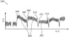
图3是根据本发明的实施方案的描绘随时间的马达电流和可用于控制基片运输模块100的曲线图300的示意性立体说明图。3 is a schematic perspective illustration of a
如上文描述,在接合位置处,压力滚筒90和压印滚筒102彼此接合,并且处理器20被配置为使滚筒90和102的线速度在接合点150处匹配。系统10还包括一个或多个电动马达,所述一个或多个电动马达被配置为使分别使ITM 44和连续目标基片50移动的滚筒90和102中的一者或两者移动。As described above, in the engaged position, the
在一些实施方案中,曲线图300中的线302包括多个点,所述多个点表示流过使滚筒90移动的电动马达的电流随时间的相应测量结果。在一些实施方案中,流过电动马达的电流的时间变化指示滚筒90和102的线速度之间的失配。应注意,施加到滚筒90和102、ITM44和连续目标基片50中的至少一者的任何非所要或未指定的力可导致流过电动马达的电流上的时间变化。例如,滚筒90和102的线速度之间的失配可致使ITM 44向滚筒90施加未指定的扭矩。In some embodiments,
在一些实施方案中,系统10可包括额外的测量能力,所述额外的测量能力被配置为测量施加到缓冲单元86和88的前述元件的扭矩和其他力中的至少一些扭矩和其他力。In some embodiments,
例如,曲线图300的点304指示当滚筒90和102之间的接合开始时流过电动马达的电流。如曲线图300中所示,接合开始的点304与终止接合的点306之间的线302的斜率指示在那个时间间隔期间的电流减小。应注意,在评估斜率时,我们忽视在曲线图300中描绘为锯齿波的电流的快速低幅变化。For example,
时间变化,诸如点304和306之间的斜率以及任何其他变化,指示在滚筒90和102之间由于其失配的速度而引起的非所要的相互作用。在图3的示例中,使滚筒90旋转的马达使滚筒90以高于滚筒102的速度的速度移动。因此,滚筒90的马达降低速度以便使滚筒90和102的线速度之间匹配。因此,流过马达的电流在点304和306之间的时间间隔期间逐渐减小。Changes in time, such as the slope between
类似地,当马达使滚筒90以低于滚筒102的线速度的线速度移动时,滚筒102拉动滚筒90(例如,由于在连续目标基片50与ITM 44之间的摩擦力),并且滚筒90的马达应更快地移动,从而导致流过滚筒90的马达的增加的电流。Similarly, when the motor moves
在一些实施方案中,处理器20被配置为从电动马达中的至少一者接收在曲线图300中示出的电流测量结果(使用任何合适的采样频率,诸如但不限于500Hz),并且例如在连续或重叠的时间间隔上或在预先限定的斜率值上评估趋势。基于时间趋势,处理器20被配置为调整电动马达中的至少一者的速度,以便通过减小电流上的时间变化而使滚筒90和102的线速度之间匹配。In some embodiments,
例如,点308和310之间的线302的时间间隔指示在额外的接合循环以及将油墨图像从ITM 44转印到连续目标基片50期间流过滚筒90的马达的电流。如图3中示出,此时间间隔的斜率基本上小于点304和306之间的线302的斜率,从而指示基础速度几乎匹配。For example, the time interval of
在曲线图300的另一示例中,线302的点312和314表示滚筒90和102之间的另一接合循环的开始和结束。在一些实施方案中,处理器20已经使滚筒90和102的线速度匹配,使得线302在点312和314之间的时间间隔期间具有零(或接近零)斜率。In another example of
应注意,滚筒90和102的线速度可由于各种原因而彼此不同,所述原因诸如为滚筒90和102之间的不同热膨胀和本文描述的其他原因。It should be noted that the linear speeds of the
图4是根据本发明的实施方案的数字印刷系统(诸如系统10)的压印站400的示意性侧视图。压印站400可取代(例如)在以上图1B中示出的压印站84。Figure 4 is a schematic side view of an
在一些实施方案中,站400包括通过相应的第一和第二马达以相应的ω1旋转速度和ω2旋转速度旋转的压印滚筒402和压力滚筒404。In some embodiments, the
在一些实施方案中,使ITM 44和连续目标基片50移动通过站400,以便将油墨图像从ITM 44转印到连续目标基片50。在站400的设置期间,在滚筒402和404之间设置预定义的距离406。在一些实施方案中,滚筒402和404中的至少一者包括编码器(未图示),所述编码器被配置为分别记录ITM 44和连续目标基片50的位置。In some embodiments, the
在一些实施方案中,处理器20被配置为从滚筒402的编码器接收指示ITM 44的相应区段的位置的多个位置信号。基于所述位置信号,处理器20被配置为计算ITM 44的线速度和滚筒402的旋转速度ω1。In some embodiments,
在一些实施方案中,处理器20被配置为调整滚筒404的旋转速度ω2,以便使ITM44和连续目标基片50的线速度之间在接合点150处匹配。在本公开的背景下并且在权利要求中,术语“旋转速度(rotational velocity)”和“旋转速度(rotary velocity)”可互换地使用,并且是指系统10的各种鼓、滚筒和辊的速度。In some embodiments,
在一些情况下,例如,由于对机械强度的不同要求或由于法规要求,不同的基片可具有不同的厚度。原则上,有可能调整每个基片的距离406,然而此调整会降低系统10的生产率,例如每小时的输出,并且还可能使其操作复杂化。In some cases, different substrates may have different thicknesses, for example due to different requirements for mechanical strength or due to regulatory requirements. In principle, it is possible to adjust the
在一些实施方案中,处理器20被配置为:接收数字信号,所述数字信号是基于指示流过站400的第一马达和第二马达中的至少一者的电流的经转换的模拟信号;以及通过改变旋转速度ω1和ω2中的至少一者来补偿连续目标基片50的不同厚度。通过向第一马达和第二马达中的至少一者施加调整过的驱动电压和/或电流,系统10可在不作出硬件或结构改变(改变距离406的值)的情况下在具有不同厚度的不同类型的基片之间切换。应注意,起初可根据目标基片的预期的典型厚度来设置距离406,例如,PET和OPP比纸张薄。在不同基片的厚度之间的较大差异(例如,两倍厚度或更多)的情况下,处理器20被配置为设置(例如)距离406的两个值,并且针对每一组对应的旋转速度进行调整。In some embodiments,
在其他实施方案中,处理器20被配置为施加相同的技术来补偿滚筒402和404中的至少一者的直径上的变化(例如,由于热膨胀),或补偿ITM 44的厚度上的变化,或补偿可能会影响站400的操作的其他非所要的影响。In other embodiments, the
在一些实施方案中,处理器20被配置为通过以下操作来改进压印过程:加强对站400的控制并且对ITM 44和连续目标基片50的线速度进行连续调整和匹配。通过改进压印过程,处理器20可改进印刷在连续目标基片50上的油墨图像的质量。In some embodiments, the
图5是根据本发明的实施方案的作为数字印刷系统10的部分的图像形成站500和烘干站502和504的示意性侧视图。图像形成站500和烘干站502可取代(例如)以上图1A的相应的站60和64,并且烘干站504可取代(例如)以上图1A的站75,或以本文描述的不同配置进行添加。5 is a schematic side view of
在一些实施方案中,图像形成站500包括多个印刷杆,诸如白色印刷杆510、黑色印刷杆530、青色印刷杆540、洋红色印刷杆550和黄色印刷杆560。In some embodiments,
在一些实施方案中,站500包括多个基于红外线的烘干机(IRD)520A-520E。每个IRD被配置为向ITM 44的面向站500的表面施加一定剂量的红外线(IR)辐射。IR辐射被配置为烘干先前施加到ITM 44的表面的油墨。在一些实施方案中,IRD中的至少一者可包括仅IR烘干机,或基于IR的烘干机与基于热空气的烘干机的组合。In some embodiments,
在一些实施方案中,站500包括具有与以上图1A的鼓风机66类似的配置的多个鼓风机511A-511E。In some embodiments,
在一些实施方案中,站500包括布置在图5的所绘示的示例性序列中的三个IRD520A-520C和两个鼓风机511A和511B,以便烘干使用印刷杆510施加到ITM 44的白色油墨。In some embodiments,
在一些实施方案中,单个鼓风机,诸如来自鼓风机511C、511D、511E和511F中的任何鼓风机,分别安装在每个印刷杆530、540、550和560之后,并且两个IRD 520D和520E安装在黄色印刷杆560与烘干机502之间。In some embodiments, a single blower, such as any from
在一些实施方案中,烘干站502包括八个鼓风机区段(未图示),其中每个鼓风机类似于以上图1A的鼓风机68。在其他实施方案中,鼓风机可布置在四个区段中,每个区段包括两个鼓风机。在替代性实施方案中,烘干站502可包括被布置成任何合适的配置的任何合适的类型和数目的烘干机。In some embodiments, drying
在一些实施方案中,烘干站504包括单个IRD,或多个IRD的阵列(未图示),并且被配置为在相应的油墨图像进入压印站之前向ITM 44施加最后剂量的IR。In some embodiments, the drying
图像形成站500的配置为了清晰起见而被简化并且是举例描述。在其他实施方案中,数字印刷系统的图像形成站可包括任何其他合适的配置。The configuration of the
虽然本文描述的实施方案主要解决了连续网状物基片上的数字印刷,但本文描述的方法和系统还可用于其他应用中。While the embodiments described herein primarily address digital printing on continuous web substrates, the methods and systems described herein can also be used in other applications.
对印刷在连续网状物基片上的图案进行基于透射的成像Transmission-based imaging of patterns printed on continuous web substrates
图6是根据本发明的实施方案的集成到数字印刷系统10中的检验站200的示意性侧视图。在一个实施方案中,在使上面印刷有图像的连续目标基片50在辊214上滚动之前,将检验站200集成到数字印刷系统10的重绕机190中。Figure 6 is a schematic side view of an
在另一实施方案中,可使用任何合适的配置将检验站200安装在数字印刷系统10的任何其他合适的站或组件上或集成到所述任何其他合适的站或组件中。In another embodiment,
如上文描述,连续目标基片50是由任何合适的材料的一个或多个层制成,所述材料诸如为聚酯、聚对苯二甲酸乙二醇酯(PET)或定向聚丙烯(OPP)或适合于呈连续网状物的形式的柔性包装的任何其他材料。此类材料对可见光部分透明,并且通常还反射可见光的至少部分。从连续目标基片50的反射可能会降低集成的检验系统产生连续目标基片50的图像和/或检测在上文描述的数字印刷过程期间形成的各种类型的过程问题和缺陷的能力。As described above, the
应注意,若干类型的过程问题和缺陷可能会出现在连续目标基片50中。例如,随机缺陷,诸如连续目标基片50的表面上或层之间的颗粒或刮擦,以及系统缺陷,诸如印刷杆62中的一者或多者中的缺失或堵塞的喷嘴。It should be noted that several types of process problems and defects may occur in the
在一些实施方案中,检验站200包括光源,在本文还称为背光模块210,所述光源被配置为使用一个或多个光束208照射连续目标基片50的下表面202。In some embodiments,
在一些实施方案中,背光模块210可包括任何合适类型的光源(未图示),诸如一个或多个发光二极管(LED)、基于荧光的光源、基于氖的光源以及一个或多个白炽灯灯泡。所述光源可包括光漫射器,或可联接到光漫射设备(未图示)。在一些实施方案中,所述光漫射设备,在本文还称为光漫射器,被配置为向检验站200提供具有均匀的照明分布的散射光,这提高了图像处理算法的性能。In some embodiments,
在一些实施方案中,背光模块210被配置为发射任何频谱的光,诸如白光、可见光内的任何选定范围,或任何频率或频率范围的不可见光(例如,红外线或紫外线)。In some embodiments,
在一些实施方案中,背光模块210被配置为使用任何照明模式发射光,所述照明模式诸如为连续照明、脉冲或具有对称或非对称形状的任何其他类型的照明模式。In some embodiments, the
在一些实施方案中,背光模块210电连接到任何合适的电力供应单元(未图示),被配置为向背光模块210供应合适的电压电流或任何其他合适的功率。In some embodiments, the
在一些实施方案中,检验站200包括图像传感器组件220,所述图像传感器组件被配置为基于透射穿过连续目标基片50的光束208的至少一部分而获取图像。In some embodiments,
在一些实施方案中,图像传感器组件220电连接到控制台12,并且被配置为响应于成像的光而产生电信号,并且例如经由电缆57向控制台12的处理器20传输所述电信号。In some embodiments,
在一些实施方案中,图像传感器组件220面向连续目标基片50和背光模块210的上表面204。在图6的示例中,在图像传感器组件220与背光模块210之间延伸的照明轴212基本上正交于连续目标基片50。在此配置中,检验站200被配置为产生施加到连续目标基片50的油墨图像的亮场图像,并且还可获取可能存在于表面202和204上或连续目标基片50内的缺陷的图像。在以下图7中详细描述缺陷的类型和几何失真。In some embodiments,
在其他实施方案中,可使用任何其他合适的配置将图像传感器组件220和/或背光模块210安装在数字印刷系统10上。例如,图像传感器组件220可包括一个或多个成像子组件(未图示),所述一个或多个成像子组件相对于照明轴212以一定角度布置,以便产生连续目标基片50的暗场图像。In other embodiments,
如以上图1B中所描述,基片运输模块100被配置为使连续目标基片50在方向99上移动。在一些实施方案中,图像传感器组件220安装在扫描设备(未图示)(例如,平台)上,所述扫描设备被配置为使图像传感器组件220在通常正交于方向99的方向206上移动。As described above in FIG. 1B , the
在一些实施方案中,处理器20被配置为控制在方向99和206上的运动曲线,以便通过在背光模块210与图像传感器组件220之间放置连续目标基片50的选定位置而从所述选定位置获取图像。In some embodiments,
在一些实施方案中,图像传感器组件220包括任何合适的相机(未图示),诸如包括(例如)联接到任何合适的透镜的12百万像素(MP)图像传感器的表面相机。In some embodiments,
在一些实施方案中,图像传感器组件220的相机可具有任何合适的视野(FOV),诸如但不限于,8cm-15cm乘4cm-8cm,所述视野被配置为提供任何合适的分辨率,诸如1000个点/英寸(dpi),这等效于25μm的像素大小。相机被配置为具有受制于FOV之间的权衡的不同分辨率和FOV。例如,相机可具有使用较小FOV的2000dpi的分辨率。In some embodiments, the camera of
在一些实施方案中,处理器20被配置为从相机接收一组FOV,并且拼接多个FOV以便显示连续目标基片50的选定的所关注区(ROI)的图像。In some embodiments, the
在一些实施方案中,系统10向连续目标基片50的表面施加白色油墨的基础层,如以上图1A中所描述。基片和白色油墨是高度反射性的,但通过使用检验站200的配置,图像传感器组件220被配置为对透射穿过连续目标基片50和白色油墨的光束208的至少一部分进行成像。In some embodiments,
在一些实施方案中,图像传感器组件220还被配置为检测透射穿过包括连续目标基片50、基础层和油墨图案的堆叠的光的不同强度。例如,白色油墨对光束208部分透明,因此,白色油墨的不同密度和/或厚度将导致所透射的束208的不同强度,并且因此导致由图像传感器组件220产生的不同电信号。在一些实施方案中,系统10被配置为通过以下操作向连续目标基片50施加不同密度和/或厚度的白色油墨以及其他色彩的油墨:控制设置在连续目标基片50的表面204上的预先限定的区域上的相应墨滴的量。In some embodiments, the
在一些实施方案中,处理器20被配置为在数字图像中产生指示(例如)施加到连续目标基片50的表面204的白色油墨的密度和/或厚度的不同灰度。In some embodiments,
在一些实施方案中,连续目标基片50可包括各种类型的印刷和/或集成标记(未图示),诸如但不限于对准标记、用于上文描述的拼接操作的拼接标记,以及条形码标记。在一些实施方案中,系统10可包括被配置为读取连续目标基片50的标记以便监测印刷过程的传感器,如将在以下图7中详细描述。In some embodiments, the
在一些实施方案中,系统10被配置为当基片运输模块100在方向99上移动连续目标基片50时使用快速扫描在方向206上扫描连续目标基片50的整个区域。另外或可替代地,系统10可包括多个检验站200,所述多个检验站例如在方向206上跨连续目标基片50的宽度而布置,以便覆盖连续目标基片50的整个区域。在其他实施方案中,系统10可包括任何其他合适的配置,诸如各自具有沿着方向206的预先限定的运动路径的多个相机,使得这些相机中的至少一些相机覆盖连续目标基片50的整个区域。In some embodiments,
在其他实施方案中,检验站200可包括多个图像传感器组件220,所述多个图像传感器组件例如在方向206上跨连续目标基片50的宽度而布置,以便使用上文描述的单个背光模块210覆盖连续目标基片50的整个区域。In other embodiments,
在图6上的示例中,背光模块210是静态的,并且图像传感器组件220是移动的。在替代性实施方案中,检验站200可具有任何其他合适的配置。例如,背光模块210和图像传感器组件220都可以能够由处理器20移动,或背光模块210可移动并且一个或多个图像传感器组件220是静态的。In the example on FIG. 6, the
举例示出检验站200的此特定配置,以便说明由本发明的实施方案解决的特定问题,并且演示这些实施方案在增强此类检验站200和系统10的性能方面的应用。然而,本发明的实施方案决不受限于这些特定种类的示例性检验站和数字印刷系统,并且本文描述的原理可类似地应用于其他种类的检验站印刷系统。例如,系统10可包括毯子检验站(未图示),所述毯子检验站具有适合于在将油墨图像转印到连续目标基片50之前检测ITM 44上的缺陷和/或失真的任何配置。所述毯子检验站可在任何合适的位置处集成到系统10中,并且可作为检验站200的补充或替代而操作。This particular configuration of
在其他实施方案中,控制台12可电连接到外部检验系统(未图示),在本文还称为独立检验系统,所述外部检验系统具有任何合适的配置,诸如检验站200的配置。所述独立检验系统被配置为对透射穿过连续目标基片50的光的至少一部分进行成像,并且响应于成像的光而产生电信号。应注意,在上文描述的印刷过程之后检验连续目标基片50的所述独立检验系统可作为检验站200的替代或补充而操作。In other embodiments,
在一些实施方案中,处理器20被配置为基于从检验站200和/或从独立检验系统接收的电信号而产生数字图像,所述检验站和独立检验系统中的每一者可检验连续目标基片50的不同区段和/或可应用不同的检验技术(硬件和软件),以便检验连续目标基片50的所讨论的不同特征,诸如标记和油墨图案。In some embodiments, the
在其他实施方案中,独立检验系统可包括一个或多个处理器、接口电路、存储器装置和其他合适的装置,以便执行前述成像和在下文描述的检测,并且可将输出文件发送到处理器20以用于改进系统10的受控操作。In other embodiments, the self-contained inspection system may include one or more processors, interface circuits, memory devices, and other suitable devices to perform the aforementioned imaging and detection described below, and may send output files to the
检测在连续网状物基片上印刷的图案中的缺陷和失真Detect defects and distortions in patterns printed on continuous web substrates
图7是根据本发明的实施方案的示意性地说明用于检测在连续目标基片50上的数字印刷中产生的缺陷的方法的流程图。如以上图6中所描述,若干类型的过程问题和缺陷可能会出现在连续目标基片50中。例如,随机缺陷,诸如连续目标基片50的表面上或层之间的颗粒或刮擦,以及系统缺陷,诸如印刷杆62中的一者或多者中的缺失或堵塞的喷嘴、印刷头之间的未对准、非均匀性和其他类型的系统缺陷。术语“系统缺陷”是指可能会由于系统10中和/或其操作中的问题而出现的缺陷。因此,系统缺陷可在每个印刷出的图像中在特定位置处重复和/或可具有特定的几何大小和/或形状。Figure 7 is a flow chart schematically illustrating a method for detecting defects produced in digital printing on a
在一些实施方案中,图7的方法的目标是使用在以上图6中描述的各种测试结构和标记来检测系统过程问题和缺陷。所述方法开始于网状物归位步骤702:在背光模块210与图像传感器组件220之间定位位于连续目标基片50的选定区段处的给定标记。在一些实施方案中,给定标记限定连续目标基片50上的检验站200的坐标系统的原点。In some embodiments, the method of FIG. 7 is aimed at detecting system process problems and defects using the various test structures and markers described above in FIG. 6 . The method begins with a
在校准步骤704,处理器34移动连续目标基片50和图像传感器组件220,使得图像传感器组件220的相机检测来自连续目标基片50的无图案区段的束208。在一些实施方案中,处理器20应用白平衡技术以校准检验站200的各种参数,诸如曝光时间、RGB通道。在一些实施方案中,所述无图案区段还用于补偿光学缺陷,诸如镜头光晕校正。In a
如以上图6中所描述,处理器20被配置为在数字图像中产生指示(例如)施加到连续目标基片50的表面204的相应色彩的油墨的密度和/或厚度的不同强度(例如,亮度)。例如,不同灰度指示施加到连续目标基片50的表面204的白色油墨的密度。类似地,具有青色油墨或任何其他色彩的高密度和/或厚层的区域可在数字图像中显现为低强度(例如,暗色彩)。As described above in FIG. 6 ,
在焦点验证步骤706,处理器20通过测试检验站200获取和聚焦于连续目标基片50的焦点校准目标或任何其他合适的图案的响应来测量检验站200的焦点。还可在支持此类操作的镜头和相机模型中执行焦点校准。In a
在基片滚动步骤708,处理器20在方向99上将连续目标基片50滚动到目标区段,在本文还称为目标线,所述目标区段包括用于测试连续目标基片50中的过程问题和系统缺陷的一个或多个目标。例如,目标线可包括用于检测黑色色彩印刷杆的一个或多个印刷杆62中的缺失的喷嘴的目标阵列。另一目标线可包括用于检测青色色彩印刷杆的一个或多个印刷杆62中的缺失的喷嘴的目标阵列。In a
在相机移动步骤710,处理器20在方向206上移动图像传感器组件220的相机,以便将相机定位成与测试方案的测试目标对准。例如,用于测试在黑色色彩印刷杆的印刷头编号9中是否存在缺失的喷嘴的目标。In a
在一些实施方案中,步骤308和310可在连续模式下执行。在这些实施方案中,处理器20在方向99上将连续目标基片50滚动到所述区段或目标阵列。随后,处理器20停止滚动连续目标基片50,并且开始在方向206上移动图像传感器组件220的相机以便使相机与期望的测试目标对准。这些实施方案还适用于校准步骤704。In some embodiments,
在其他实施方案中,步骤308和310可在同时模式下执行。在这些实施方案中,处理器20在方向99上将连续目标基片50滚动到目标区段,并且同时在方向206上移动图像传感器组件220的相机以便使相机与测试目标对准。这些实施方案还适用于校准步骤704。In other embodiments,
在一个实施方案中,当系统10将图像印刷在产品基片而不是测试基片上时,还可在生产中执行所述同时模式。在此实施方案中,图像形成站60产生摆放在产品图像之间或连续目标基片50上的任何其他合适的位置处的测试目标。在产生印刷出的图像期间,在将图像印刷在产品基片上期间,处理器20在滚动连续目标基片50的同时将图像传感器组件220的相机移动到期望的测试目标。In one embodiment, the simultaneous mode can also be performed in production when the
在图像获取步骤712,处理器20将相机应用于前述目标以便获取其图像。In an
如以上在图6中所描述,每个目标可具有标记,诸如条形码,所述标记指向查找表(或任何其他类型的文件)中的注册表。在条形码检测和读取步骤714,处理器20检测和读取条形码。As described above in Figure 6, each object may have a label, such as a barcode, that points to a registry in a lookup table (or any other type of file). In a barcode detection and reading
在一些实施方案中,条形码可描述被测试的特征(例如,印刷头编号9的黑色色彩喷嘴)、测试类型(对堵塞的喷嘴的检测)和将应用于所获取的图像的算法。In some embodiments, the barcode may describe the feature being tested (eg, printhead number 9 black colored nozzle), the type of test (detection of clogged nozzles), and the algorithm to be applied to the captured image.
在其他实施方案中,所述方法可通过使用任何其他合适的技术取代条形码来排除条形码检测和读取步骤714。例如,可基于检验站200的坐标系统中的给定目标的位置来设置与给定的被测试的特征相关联的信息。In other embodiments, the method may eliminate the barcode detection and reading
在图像分析步骤716,处理器20向由图像传感器组件220获取的图像应用与在所述图像中示出的测试特征相对应的一种或多种算法。所述算法分析图像,并且处理器20保存(例如)具有以下各项的指示符的结果:印刷杆编号9的黑色色彩喷嘴是否在系统10的规范内起作用,或在此喷嘴被部分堵塞或完全堵塞的情况下的警告。At
在目标线决策步骤718,处理器20检查目标线是否具有作为测试方案的部分并且尚未访问的额外目标。如果在同一目标线中存在额外的目标要测试(例如,印刷杆编号8的黑色色彩喷嘴),则所述方法循环回到相机移动步骤710,并且处理器20沿着方向206移动图像传感器组件220的相机,以便将相机定位在同一目标线和测试方案的下一个测试目标上方。In a target
在分析了目标线中的最后一个目标之后,处理器在扫描完成步骤720检查在测试方案中是否存在额外的目标线。在存在额外的目标线的情况下,所述方法循环回到基片滚动步骤708,并且处理器20使基片滚动到下一个目标线。例如,包括用于测试印刷杆62的青色色彩喷嘴的目标的目标线,以及用于测试印刷杆62的所有其他色彩(例如,黄色、洋红色和白色)的喷嘴的类似(或不同的)目标线。After analyzing the last target in the target line, the processor checks at scan
在结束了最后一个目标线之后,在报告步骤722,处理器20输出被测试的喷嘴中的每一者的状态报告。所述报告概括了处于系统10的规范内的喷嘴和出故障的喷嘴,并且还生成纠正文件。After finishing the last target line, at reporting
在结束所述方法的实施步骤724,处理器20向图像形成站60和系统10的其他站和组件施加纠正动作。At an
在其他实施方案中,图7的方法可适用于监测和分析系统10的一个或多个站、模块和组件的任何其他故障。In other embodiments, the method of FIG. 7 may be adapted to monitor and analyze any other failure of one or more stations, modules, and components of
例如,可应用相同的方法来监测印刷杆校准,诸如对印刷头的机械对准以及其他问题和缺陷,诸如但不限于印刷非均匀性和色彩配准错误。For example, the same method can be applied to monitor printbar alignment, such as mechanical alignment to the printhead, as well as other problems and defects, such as but not limited to printing non-uniformity and color registration errors.
虽然本文描述的实施方案主要解决了连续网状物基片上的数字印刷,但本文描述的方法和系统还可用于其他应用中,诸如用于片材馈送印刷检验中。While the embodiments described herein primarily address digital printing on continuous web substrates, the methods and systems described herein may also be used in other applications, such as in sheet-fed print inspection.
因此将了解,上文描述的实施方案是举例叙述,并且本发明不限于上文已经具体示出和描述的内容。而是,本发明的范围包括上文描述的各种特征的组合和子组合两者,以及本领域技术人员在阅读了前述描述之后将想到的并且在现有技术中未公开的其变化和修改。以引用的方式并入本专利申请中的文献将被视为该申请的整体部分,不同之处在于,在这些并入的文献中以与在本说明书中明确或含蓄作出的定义冲突的方式定义任何术语的程度上,仅应考虑本说明书中的定义。It will therefore be appreciated that the above described embodiments are by way of example and that the invention is not limited to what has been particularly shown and described above. Rather, the scope of the present invention includes both combinations and subcombinations of the various features described above, as well as variations and modifications thereof which would occur to those skilled in the art after reading the foregoing description and which have not been disclosed in the prior art. Documents incorporated by reference into this patent application are to be considered an integral part of this application except that, in such incorporated documents, definitions are defined in a manner that conflicts with definitions made expressly or implicitly in this specification. To the extent any term is used, only its definition in this specification should be considered.
Claims (28)
Applications Claiming Priority (6)
| Application Number | Priority Date | Filing Date | Title |
|---|---|---|---|
| US201862784579P | 2018-12-24 | 2018-12-24 | |
| US201862784576P | 2018-12-24 | 2018-12-24 | |
| US62/784,579 | 2018-12-24 | ||
| US62/784,576 | 2018-12-24 | ||
| PCT/IB2019/061081WO2020136517A1 (en) | 2018-12-24 | 2019-12-19 | A digital printing system |
| CN201980085646.5ACN113272144B (en) | 2018-12-24 | 2019-12-19 | Digital printing system and method |
Related Parent Applications (1)
| Application Number | Title | Priority Date | Filing Date |
|---|---|---|---|
| CN201980085646.5ADivisionCN113272144B (en) | 2018-12-24 | 2019-12-19 | Digital printing system and method |
Publications (1)
| Publication Number | Publication Date |
|---|---|
| CN116080260Atrue CN116080260A (en) | 2023-05-09 |
Family
ID=71128473
Family Applications (2)
| Application Number | Title | Priority Date | Filing Date |
|---|---|---|---|
| CN202310285782.7APendingCN116080260A (en) | 2018-12-24 | 2019-12-19 | Digital printing system and method |
| CN201980085646.5AActiveCN113272144B (en) | 2018-12-24 | 2019-12-19 | Digital printing system and method |
Family Applications After (1)
| Application Number | Title | Priority Date | Filing Date |
|---|---|---|---|
| CN201980085646.5AActiveCN113272144B (en) | 2018-12-24 | 2019-12-19 | Digital printing system and method |
Country Status (5)
| Country | Link |
|---|---|
| US (3) | US11787170B2 (en) |
| EP (1) | EP3902680B1 (en) |
| JP (2) | JP7462648B2 (en) |
| CN (2) | CN116080260A (en) |
| WO (1) | WO2020136517A1 (en) |
Families Citing this family (26)
| Publication number | Priority date | Publication date | Assignee | Title |
|---|---|---|---|---|
| US12053978B2 (en) | 2012-03-05 | 2024-08-06 | Landa Corporation Ltd. | Digital printing system |
| HK1204640A1 (en) | 2012-03-05 | 2015-11-27 | Landa Corporation Ltd. | Ink film constructions |
| US9643403B2 (en) | 2012-03-05 | 2017-05-09 | Landa Corporation Ltd. | Printing system |
| US11809100B2 (en) | 2012-03-05 | 2023-11-07 | Landa Corporation Ltd. | Intermediate transfer members for use with indirect printing systems and protonatable intermediate transfer members for use with indirect printing systems |
| US9498946B2 (en) | 2012-03-05 | 2016-11-22 | Landa Corporation Ltd. | Apparatus and method for control or monitoring of a printing system |
| JP6437312B2 (en) | 2012-03-05 | 2018-12-12 | ランダ コーポレイション リミテッド | Digital printing process |
| GB201401173D0 (en) | 2013-09-11 | 2014-03-12 | Landa Corp Ltd | Ink formulations and film constructions thereof |
| GB2536489B (en) | 2015-03-20 | 2018-08-29 | Landa Corporation Ltd | Indirect printing system |
| JP6980704B2 (en) | 2016-05-30 | 2021-12-15 | ランダ コーポレイション リミテッド | Digital printing process |
| GB201609463D0 (en) | 2016-05-30 | 2016-07-13 | Landa Labs 2012 Ltd | Method of manufacturing a multi-layer article |
| CN114148099B (en) | 2016-05-30 | 2025-03-14 | 兰达公司 | Digital printing methods |
| US11267239B2 (en) | 2017-11-19 | 2022-03-08 | Landa Corporation Ltd. | Digital printing system |
| US11707943B2 (en) | 2017-12-06 | 2023-07-25 | Landa Corporation Ltd. | Method and apparatus for digital printing |
| CN117885446A (en) | 2018-06-26 | 2024-04-16 | 兰达公司 | Intermediate transmission components of digital printing systems |
| US10994528B1 (en) | 2018-08-02 | 2021-05-04 | Landa Corporation Ltd. | Digital printing system with flexible intermediate transfer member |
| US12001902B2 (en) | 2018-08-13 | 2024-06-04 | Landa Corporation Ltd. | Correcting distortions in digital printing by implanting dummy pixels in a digital image |
| WO2020075012A1 (en) | 2018-10-08 | 2020-04-16 | Landa Corporation Ltd. | Friction reduction means for printing systems and method |
| CN116080260A (en) | 2018-12-24 | 2023-05-09 | 兰达公司 | Digital printing system and method |
| US12358277B2 (en) | 2019-03-31 | 2025-07-15 | Landa Corporation Ltd. | Systems and methods for preventing or minimizing printing defects in printing processes |
| US11912022B2 (en) | 2019-08-20 | 2024-02-27 | Landa Corporation Ltd. | Apparatus for controlling tension applied to a flexible member |
| JP7685995B2 (en) | 2019-11-25 | 2025-05-30 | ランダ コーポレイション リミテッド | Drying of ink in digital printing using infrared radiation absorbed by particles embedded within an ITM |
| JP7657229B2 (en) | 2019-12-29 | 2025-04-04 | ランダ コーポレイション リミテッド | Printing method and system |
| CN116057136B (en) | 2020-07-29 | 2025-02-28 | 兰达公司 | Inkjet ink formulations and uses thereof |
| EP4264377A4 (en)* | 2021-02-02 | 2024-11-13 | Landa Corporation Ltd. | REDUCING DISTORTIONS IN PRINTED IMAGES |
| EP4334136A4 (en)* | 2021-06-15 | 2025-04-09 | Landa Corporation Ltd. | DIGITAL PRINTING SYSTEM AND PROCESS |
| JP2025513854A (en) | 2022-04-14 | 2025-04-30 | ランダ コーポレイション リミテッド | Inkjet Ink Formulations |
Citations (9)
| Publication number | Priority date | Publication date | Assignee | Title |
|---|---|---|---|---|
| JP2003136693A (en)* | 2001-10-30 | 2003-05-14 | Konica Corp | Imaging apparatus |
| JP2008087287A (en)* | 2006-09-29 | 2008-04-17 | Fujifilm Corp | Ink ejection failure detection method and image forming apparatus |
| JP2008129354A (en)* | 2006-11-21 | 2008-06-05 | Ricoh Co Ltd | Image forming apparatus |
| CN102566359A (en)* | 2008-05-27 | 2012-07-11 | 佳能株式会社 | Color-image forming apparatus |
| JP2013250190A (en)* | 2012-06-01 | 2013-12-12 | Toppan Printing Co Ltd | Inspection method and inspection apparatus of printed matter |
| CN104220935A (en)* | 2012-03-05 | 2014-12-17 | 兰达公司 | Control apparatus and method for digital printing system |
| CN105164588A (en)* | 2013-04-18 | 2015-12-16 | 佳能株式会社 | Image formation device |
| US20160207306A1 (en)* | 2013-09-11 | 2016-07-21 | Landa Corporation Ltd. | Treatment of release layer |
| CN107433780A (en)* | 2016-05-25 | 2017-12-05 | 海德堡印刷机械股份公司 | Method for identifying the print nozzles failure in ink-jet printer |
Family Cites Families (858)
| Publication number | Priority date | Publication date | Assignee | Title |
|---|---|---|---|---|
| GB748821A (en) | 1950-09-29 | 1956-05-09 | British Broadcasting Corp | Improvements in and relating to television cameras |
| US2839181A (en) | 1954-12-31 | 1958-06-17 | Adamson Stephens Mfg Co | Movable tubular conveyor belt |
| NL235287A (en) | 1958-01-20 | |||
| US3053319A (en) | 1960-12-14 | 1962-09-11 | Beloit Iron Works | Web dewatering apparatus |
| US3697551A (en) | 1968-12-31 | 1972-10-10 | Hercules Inc | Silane sulfonyl azides |
| BE758713A (en) | 1969-11-12 | 1971-05-10 | Rhone Poulenc Sa | IMINOXYORGANOXYSILANES |
| NL175512C (en) | 1970-04-17 | 1984-11-16 | Jonkers Cornelius Otto | METHOD FOR OPERATING A BELT CONVEYOR AND LOAD CONVEYOR SUITABLE FOR CARRYING OUT THIS METHOD |
| JPS4843941A (en) | 1971-10-07 | 1973-06-25 | ||
| CA977818A (en) | 1972-06-30 | 1975-11-11 | Carl H. Hertz | Liquid jet recorder with contact image transfer to plural continuous paper webs |
| US3902798A (en) | 1974-03-15 | 1975-09-02 | Magicam Inc | Composite photography system |
| JPS50137744A (en) | 1974-04-20 | 1975-11-01 | ||
| US3935055A (en) | 1974-08-30 | 1976-01-27 | Nupla Corporation | Assembly tool for use in attaching fiberglass tool handles |
| US3914540A (en) | 1974-10-03 | 1975-10-21 | Magicam Inc | Optical node correcting circuit |
| US3947113A (en) | 1975-01-20 | 1976-03-30 | Itek Corporation | Electrophotographic toner transfer apparatus |
| DE2632243C3 (en) | 1976-07-17 | 1979-08-30 | Heidelberger Druckmaschinen Ag, 6900 Heidelberg | Transfer drum for printing machines that can be adjusted to variable sheet lengths |
| US4093764A (en) | 1976-10-13 | 1978-06-06 | Dayco Corporation | Compressible printing blanket |
| JPS5578904A (en) | 1978-12-11 | 1980-06-14 | Haruo Yokoyama | Teeth of slide fastner |
| JPS5581163A (en) | 1978-12-13 | 1980-06-18 | Ricoh Co Ltd | Recorder |
| JPS57121446U (en) | 1981-01-24 | 1982-07-28 | ||
| JPS57159865A (en) | 1981-03-27 | 1982-10-02 | Toray Silicone Co Ltd | Primer composition for bonding |
| JPS58174950A (en) | 1982-04-08 | 1983-10-14 | Manabu Fukuda | Rotary press printing band type relief plate |
| GB2129333B (en) | 1982-08-23 | 1986-11-19 | Canon Kk | Recording medium |
| US4520048A (en) | 1983-01-17 | 1985-05-28 | International Octrooi Maatschappij "Octropa" B.V. | Method and apparatus for coating paper and the like |
| JPS59171975A (en) | 1983-03-19 | 1984-09-28 | Ricoh Co Ltd | Transfer type electrostatic recording method |
| US4538156A (en) | 1983-05-23 | 1985-08-27 | At&T Teletype Corporation | Ink jet printer |
| JPS6076343A (en) | 1983-10-03 | 1985-04-30 | Toray Ind Inc | Ink jet dying |
| JPS60199692A (en) | 1984-03-23 | 1985-10-09 | Seiko Epson Corp | printing device |
| EP0183795A1 (en) | 1984-06-18 | 1986-06-11 | The Gillette Company | Pigmented aqueous ink compositions and method |
| US4555437A (en) | 1984-07-16 | 1985-11-26 | Xidex Corporation | Transparent ink jet recording medium |
| US4575465A (en) | 1984-12-13 | 1986-03-11 | Polaroid Corporation | Ink jet transparency |
| JPS6223783A (en) | 1985-07-25 | 1987-01-31 | Canon Inc | Thermal transfer recording method |
| US4792473A (en) | 1986-10-31 | 1988-12-20 | Endura Tape, Inc. | Self adhesive wallboard tape |
| JPS63274572A (en) | 1987-05-01 | 1988-11-11 | Canon Inc | Image forming device |
| JP2529651B2 (en) | 1987-06-22 | 1996-08-28 | 大阪シ−リング印刷株式会社 | Thermal transfer ink and thermal transfer sheet using the same |
| US4867830A (en) | 1988-05-26 | 1989-09-19 | Chung Nan Y | Method of tabbing pressure sensitive tape |
| US4853737A (en) | 1988-05-31 | 1989-08-01 | Eastman Kodak Company | Roll useful in electrostatography |
| US4976197A (en) | 1988-07-27 | 1990-12-11 | Ryobi, Ltd. | Reverse side printing device employing sheet feed cylinder in sheet-fed printer |
| US5039339A (en) | 1988-07-28 | 1991-08-13 | Eastman Kodak Company | Ink composition containing a blend of a polyester and an acrylic polymer |
| US5062364A (en) | 1989-03-29 | 1991-11-05 | Presstek, Inc. | Plasma-jet imaging method |
| DE59009466D1 (en) | 1989-10-26 | 1995-09-07 | Ciba Geigy Ag | Aqueous printing inks for inkjet printing. |
| US5190582A (en) | 1989-11-21 | 1993-03-02 | Seiko Epson Corporation | Ink for ink-jet printing |
| US6009284A (en) | 1989-12-13 | 1999-12-28 | The Weinberger Group, L.L.C. | System and method for controlling image processing devices from a remote location |
| JPH03248170A (en) | 1990-02-27 | 1991-11-06 | Fujitsu Ltd | Double-sided printing mechanism |
| JPH0698814B2 (en) | 1990-03-13 | 1994-12-07 | 富士ゼロックス株式会社 | Reproducing method of ink recording medium |
| US5075731A (en) | 1990-03-13 | 1991-12-24 | Sharp Kabushiki Kaisha | Transfer roller device |
| US5012072A (en) | 1990-05-14 | 1991-04-30 | Xerox Corporation | Conformable fusing system |
| US5365324A (en) | 1990-10-12 | 1994-11-15 | Canon Kabushiki Kaisha | Multi-image forming apparatus |
| US5099256A (en) | 1990-11-23 | 1992-03-24 | Xerox Corporation | Ink jet printer with intermediate drum |
| CA2059867A1 (en) | 1991-02-13 | 1992-08-14 | Miles Inc. | Binder and vehicle for inks and other color formulations |
| US5128091A (en) | 1991-02-25 | 1992-07-07 | Xerox Corporation | Processes for forming polymeric seamless belts and imaging members |
| US5246100A (en) | 1991-03-13 | 1993-09-21 | Illinois Tool Works, Inc. | Conveyor belt zipper |
| US5352507A (en) | 1991-04-08 | 1994-10-04 | W. R. Grace & Co.-Conn. | Seamless multilayer printing blanket |
| US5777576A (en) | 1991-05-08 | 1998-07-07 | Imagine Ltd. | Apparatus and methods for non impact imaging and digital printing |
| US5575873A (en) | 1991-08-06 | 1996-11-19 | Minnesota Mining And Manufacturing Company | Endless coated abrasive article |
| EP0598717B2 (en) | 1991-08-14 | 2004-12-22 | Hewlett-Packard Indigo B.V. | Duplex printer |
| JP3223927B2 (en) | 1991-08-23 | 2001-10-29 | セイコーエプソン株式会社 | Transfer type recording device |
| WO1993007000A1 (en) | 1991-10-04 | 1993-04-15 | Indigo N.V. | Ink-jet printer |
| JPH05147208A (en) | 1991-11-30 | 1993-06-15 | Mita Ind Co Ltd | Ink jet printer |
| JP2778331B2 (en) | 1992-01-29 | 1998-07-23 | 富士ゼロックス株式会社 | Ink jet recording device |
| JPH06171076A (en) | 1992-12-07 | 1994-06-21 | Seiko Epson Corp | Transfer type inkjet printer |
| US5349905A (en) | 1992-03-24 | 1994-09-27 | Xerox Corporation | Method and apparatus for controlling peak power requirements of a printer |
| JP3036226B2 (en) | 1992-04-20 | 2000-04-24 | 富士ゼロックス株式会社 | Transfer material transfer device for image forming equipment |
| TW219419B (en) | 1992-05-21 | 1994-01-21 | Ibm | Mobile data terminal with external antenna |
| JPH06954A (en) | 1992-06-17 | 1994-01-11 | Seiko Epson Corp | Inkjet recording method |
| US5623296A (en) | 1992-07-02 | 1997-04-22 | Seiko Epson Corporation | Intermediate transfer ink jet recording method |
| US5264904A (en) | 1992-07-17 | 1993-11-23 | Xerox Corporation | High reliability blade cleaner system |
| DE69321789T2 (en) | 1992-08-12 | 1999-06-10 | Seiko Epson Corp., Tokio/Tokyo | Ink jet recording method and apparatus |
| JPH06100807A (en) | 1992-09-17 | 1994-04-12 | Seiko Instr Inc | Recording ink |
| US5502476A (en) | 1992-11-25 | 1996-03-26 | Tektronix, Inc. | Method and apparatus for controlling phase-change ink temperature during a transfer printing process |
| US5902841A (en) | 1992-11-25 | 1999-05-11 | Tektronix, Inc. | Use of hydroxy-functional fatty amides in hot melt ink jet inks |
| US5305099A (en) | 1992-12-02 | 1994-04-19 | Joseph A. Morcos | Web alignment monitoring system |
| JP3314971B2 (en) | 1993-01-28 | 2002-08-19 | 理想科学工業株式会社 | Emulsion ink for stencil printing |
| JP3074105B2 (en) | 1993-05-13 | 2000-08-07 | 株式会社桜井グラフィックシステムズ | Sheet reversing mechanism of sheet-fed printing press |
| JPH06345284A (en) | 1993-06-08 | 1994-12-20 | Seiko Epson Corp | Belt conveyor and intermediate transfer type ink jet recording apparatus using the same |
| US5333771A (en) | 1993-07-19 | 1994-08-02 | Advance Systems, Inc. | Web threader having an endless belt formed from a thin metal strip |
| US5677719A (en) | 1993-09-27 | 1997-10-14 | Compaq Computer Corporation | Multiple print head ink jet printer |
| JPH07112841A (en) | 1993-10-18 | 1995-05-02 | Canon Inc | Sheet conveying apparatus and image forming apparatus |
| JPH07186453A (en) | 1993-12-27 | 1995-07-25 | Toshiba Corp | Color image forming device |
| CN1071264C (en) | 1994-02-14 | 2001-09-19 | 曼弗雷德·R·屈恩勒 | Conveying systems such as printing equipment with static electricity to maintain the precise positioning and alignment of the substrate |
| JPH07238243A (en) | 1994-03-01 | 1995-09-12 | Seiko Instr Inc | Recording ink |
| US5642141A (en) | 1994-03-08 | 1997-06-24 | Sawgrass Systems, Inc. | Low energy heat activated transfer printing process |
| JPH07278490A (en) | 1994-04-06 | 1995-10-24 | Dainippon Toryo Co Ltd | Aqueous coating composition |
| EP0685420B1 (en) | 1994-06-03 | 1998-08-05 | Ferag AG | Method for controlling the manufacture of printed products and assembly for carrying out the method |
| US5614933A (en) | 1994-06-08 | 1997-03-25 | Tektronix, Inc. | Method and apparatus for controlling phase-change ink-jet print quality factors |
| EP0773974A4 (en) | 1994-08-02 | 1998-04-08 | Lord Corp | Aqueous silane adhesive compositions |
| NL9401352A (en) | 1994-08-22 | 1996-04-01 | Oce Nederland Bv | Device for transferring toner images. |
| JPH0862999A (en) | 1994-08-26 | 1996-03-08 | Toray Ind Inc | Intermediate transfer body and image forming method using same |
| US5883144A (en) | 1994-09-19 | 1999-03-16 | Sentinel Products Corp. | Silane-grafted materials for solid and foam applications |
| US5929129A (en) | 1994-09-19 | 1999-07-27 | Sentinel Products Corp. | Crosslinked foamable compositions of silane-grafted, essentially linear polyolefins blended with polypropylene |
| JP4057657B2 (en) | 1994-09-19 | 2008-03-05 | センチネル・プロダクツ・コープ | Crosslinked foam structure of linear polyolefin and method for producing the same |
| US5932659A (en) | 1994-09-19 | 1999-08-03 | Sentinel Products Corp. | Polymer blend |
| JP3720396B2 (en) | 1994-10-17 | 2005-11-24 | 富士写真フイルム株式会社 | Thermal transfer recording material |
| JPH08231075A (en)* | 1994-11-22 | 1996-09-10 | Xerox Corp | High accuracy speed control device and method |
| IL111845A (en) | 1994-12-01 | 2004-06-01 | Hewlett Packard Indigo Bv | Imaging apparatus and method and liquid toner therefor |
| US6108513A (en) | 1995-04-03 | 2000-08-22 | Indigo N.V. | Double sided imaging |
| IL113235A (en) | 1995-04-03 | 2006-07-17 | Hewlett Packard Indigo Bv | Double sided imaging |
| US5532314A (en) | 1995-05-03 | 1996-07-02 | Lord Corporation | Aqueous silane-phenolic adhesive compositions, their preparation and use |
| JPH08333531A (en) | 1995-06-07 | 1996-12-17 | Xerox Corp | Water-base ink-jet ink composition |
| US5679463A (en) | 1995-07-31 | 1997-10-21 | Eastman Kodak Company | Condensation-cured PDMS filled with zinc oxide and tin oxide mixed fillers for improved fusing member materials |
| US5780412A (en) | 1995-08-09 | 1998-07-14 | The Sherwin-Williams Company | Alkaline-stable hard surface cleaning compounds combined with alkali-metal organosiliconates |
| TW300204B (en) | 1995-08-25 | 1997-03-11 | Avery Dennison Corp | |
| JPH09123432A (en) | 1995-11-02 | 1997-05-13 | Mita Ind Co Ltd | Transfer ink jet recorder |
| US5683841A (en) | 1995-11-17 | 1997-11-04 | Fuji Photo Film Co., Ltd. | Method for preparation of waterless lithographic printing plate by electrophotographic process |
| JP3301295B2 (en) | 1995-12-01 | 2002-07-15 | 東洋インキ製造株式会社 | Method for producing finely divided pigment |
| US6554189B1 (en) | 1996-10-07 | 2003-04-29 | Metrologic Instruments, Inc. | Automated system and method for identifying and measuring packages transported through a laser scanning tunnel |
| JP3597289B2 (en) | 1995-12-28 | 2004-12-02 | 花王株式会社 | Stretchable material, method for producing the same, and product using the same |
| EP0784244B1 (en) | 1996-01-10 | 2003-03-12 | Canon Kabushiki Kaisha | Intermediate transfer member and electrophotographic apparatus including same |
| US6811840B1 (en) | 1996-02-23 | 2004-11-02 | Stahls' Inc. | Decorative transfer process |
| EP0890138A1 (en) | 1996-03-28 | 1999-01-13 | Minnesota Mining And Manufacturing Company | Perfluoroether release coatings for organic photoreceptors |
| JPH09268266A (en) | 1996-04-01 | 1997-10-14 | Toyo Ink Mfg Co Ltd | Ink jet recording liquid |
| JP3758232B2 (en) | 1996-04-15 | 2006-03-22 | セイコーエプソン株式会社 | Image carrier belt drive mechanism |
| US5660108A (en) | 1996-04-26 | 1997-08-26 | Presstek, Inc. | Modular digital printing press with linking perfecting assembly |
| JPH09300678A (en) | 1996-05-20 | 1997-11-25 | Mitsubishi Electric Corp | Recording device |
| JP3737562B2 (en) | 1996-05-31 | 2006-01-18 | 富士写真フイルム株式会社 | Image forming apparatus |
| JP3225889B2 (en) | 1996-06-27 | 2001-11-05 | 富士ゼロックス株式会社 | Toner for electrostatic latent image developer, method for producing the same, electrostatic latent image developer, and image forming method |
| DE69703927T2 (en) | 1996-08-01 | 2001-05-10 | Seiko Epson Corp., Tokio/Tokyo | INK-JET PRINTING METHOD USING TWO LIQUIDS |
| US5736250A (en) | 1996-08-08 | 1998-04-07 | Xerox Corporation | Crosslinked latex polymer surfaces and methods thereof |
| JP3802616B2 (en) | 1996-08-19 | 2006-07-26 | シャープ株式会社 | Inkjet recording method |
| DE69712279D1 (en) | 1996-08-22 | 2002-06-06 | Sony Corp | Printers and printing processes |
| US5889534A (en) | 1996-09-10 | 1999-03-30 | Colorspan Corporation | Calibration and registration method for manufacturing a drum-based printing system |
| US5733698A (en) | 1996-09-30 | 1998-03-31 | Minnesota Mining And Manufacturing Company | Release layer for photoreceptors |
| JPH10119429A (en) | 1996-10-11 | 1998-05-12 | Arkwright Inc | Ink jet ink absorption film composite |
| US5978638A (en) | 1996-10-31 | 1999-11-02 | Canon Kabushiki Kaisha | Intermediate transfer belt and image forming apparatus adopting the belt |
| JPH10130597A (en) | 1996-11-01 | 1998-05-19 | Sekisui Chem Co Ltd | Curable adhesive sheet and method for producing the same |
| US5777650A (en) | 1996-11-06 | 1998-07-07 | Tektronix, Inc. | Pressure roller |
| JP3216799B2 (en) | 1996-11-13 | 2001-10-09 | 松下電工株式会社 | Heat fixing roll |
| US6221928B1 (en) | 1996-11-15 | 2001-04-24 | Sentinel Products Corp. | Polymer articles including maleic anhydride |
| JP2938403B2 (en) | 1996-12-13 | 1999-08-23 | 住友ゴム工業株式会社 | Printing blanket |
| US6072976A (en) | 1996-12-17 | 2000-06-06 | Bridgestone Corporation | Intermediate transfer member for electrostatic recording |
| US5761595A (en) | 1997-01-21 | 1998-06-02 | Xerox Corporation | Intermediate transfer members |
| US6071368A (en) | 1997-01-24 | 2000-06-06 | Hewlett-Packard Co. | Method and apparatus for applying a stable printed image onto a fabric substrate |
| GB2321616B (en) | 1997-01-29 | 1999-11-17 | Bond A Band Transmissions Ltd | Band joining system |
| US5698018A (en) | 1997-01-29 | 1997-12-16 | Eastman Kodak Company | Heat transferring inkjet ink images |
| US6354700B1 (en) | 1997-02-21 | 2002-03-12 | Ncr Corporation | Two-stage printing process and apparatus for radiant energy cured ink |
| US5891934A (en) | 1997-03-24 | 1999-04-06 | Hewlett-Packard Company | Waterfast macromolecular chromophores using amphiphiles |
| US6720367B2 (en) | 1997-03-25 | 2004-04-13 | Seiko Epson Corporation | Ink composition comprising cationic, water-soluble resin |
| US6024018A (en) | 1997-04-03 | 2000-02-15 | Intex Israel Technologies Corp., Ltd | On press color control system |
| EP0875544B1 (en) | 1997-04-28 | 2002-12-11 | Seiko Epson Corporation | Ink composition capable of realizing light fast image |
| US6551716B1 (en) | 1997-06-03 | 2003-04-22 | Indigo N.V. | Intermediate transfer blanket and method of producing the same |
| US6332943B1 (en) | 1997-06-30 | 2001-12-25 | Basf Aktiengesellschaft | Method of ink-jet printing with pigment preparations having a dispersant |
| KR200147792Y1 (en) | 1997-06-30 | 1999-06-15 | 윤종용 | Wet electrophotographic printer |
| JPH1184893A (en) | 1997-07-07 | 1999-03-30 | Fuji Xerox Co Ltd | Intermediate transfer body and image forming device using the same |
| KR200151066Y1 (en) | 1997-07-18 | 1999-07-15 | 윤종용 | Color laser printer |
| JPH1191147A (en) | 1997-07-22 | 1999-04-06 | Ricoh Co Ltd | Image forming method and apparatus |
| US5865299A (en) | 1997-08-15 | 1999-02-02 | Williams; Keith | Air cushioned belt conveyor |
| US6397034B1 (en) | 1997-08-29 | 2002-05-28 | Xerox Corporation | Fluorinated carbon filled polyimide intermediate transfer components |
| AU3749297A (en) | 1997-09-11 | 1999-03-25 | Scapa Group Plc | Filter belt guide |
| US6053307A (en) | 1997-09-19 | 2000-04-25 | Honda Sangyo Kabushiki Kaisha | Apparatus for changing and guiding running direction of conveyor belt |
| US6045817A (en) | 1997-09-26 | 2000-04-04 | Diversey Lever, Inc. | Ultramild antibacterial cleaning composition for frequent use |
| US6827018B1 (en) | 1997-09-26 | 2004-12-07 | Heidelberger Druckmaschinen Ag | Device and method for driving a printing machine with multiple uncoupled motors |
| JPH11106081A (en) | 1997-10-01 | 1999-04-20 | Ricoh Co Ltd | Photosensitive belt stopping mechanism of electrophotographic device |
| US6471803B1 (en) | 1997-10-24 | 2002-10-29 | Ray Pelland | Rotary hot air welder and stitchless seaming |
| US6024786A (en) | 1997-10-30 | 2000-02-15 | Hewlett-Packard Company | Stable compositions of nano-particulate unmodified pigments and insoluble colorants in aqueous microemulsions, and principle of stability and methods of formation thereof |
| JPH11138740A (en) | 1997-11-05 | 1999-05-25 | Nikka Kk | Manufacture of doctor blade |
| JP3634952B2 (en) | 1997-11-18 | 2005-03-30 | 株式会社金陽社 | Manufacturing method of transfer belt for electronic equipment |
| JP4033363B2 (en) | 1997-11-28 | 2008-01-16 | リコープリンティングシステムズ株式会社 | Transfer belt and electrophotographic apparatus using the same |
| KR100252101B1 (en) | 1997-12-12 | 2000-04-15 | 윤종용 | Developer Supply Method of Wet Developer |
| DE69818411T2 (en) | 1997-12-26 | 2004-06-24 | Ricoh Co., Ltd. | Inkjet printing using a viscosity-improving layer |
| US6155669A (en) | 1998-01-08 | 2000-12-05 | Xerox Corporation | Pagewidth ink jet printer including a printbar mounted encoding system |
| US6126777A (en) | 1998-02-20 | 2000-10-03 | Lord Corporation | Aqueous silane adhesive compositions |
| US6199971B1 (en) | 1998-02-24 | 2001-03-13 | Arrray Printers Ab | Direct electrostatic printing method and apparatus with increased print speed |
| US6213580B1 (en) | 1998-02-25 | 2001-04-10 | Xerox Corporation | Apparatus and method for automatically aligning print heads |
| US6499822B1 (en) | 1998-04-27 | 2002-12-31 | Canon Kabushiki Kaisha | Method and apparatus for forming an image on a recording medium with contraction and expansion properties |
| JPH11327315A (en) | 1998-05-12 | 1999-11-26 | Brother Ind Ltd | Transfer device and image forming device |
| WO1999061957A1 (en) | 1998-05-24 | 1999-12-02 | Indigo N.V. | Printing system |
| US6912952B1 (en) | 1998-05-24 | 2005-07-05 | Hewlett-Packard Indigo B.V. | Duplex printing system |
| US6109746A (en) | 1998-05-26 | 2000-08-29 | Eastman Kodak Company | Delivering mixed inks to an intermediate transfer roller |
| US6234625B1 (en) | 1998-06-26 | 2001-05-22 | Eastman Kodak Company | Printing apparatus with receiver treatment |
| US6625331B1 (en) | 1998-07-03 | 2003-09-23 | Minolta Co., Ltd. | Image forming apparatus |
| US6195112B1 (en) | 1998-07-16 | 2001-02-27 | Eastman Kodak Company | Steering apparatus for re-inkable belt |
| EP0985715B1 (en) | 1998-09-01 | 2011-10-12 | Mitsubishi Chemical Corporation | Recording liquid, printed product and ink jet recording method |
| JP2000082141A (en)* | 1998-09-07 | 2000-03-21 | Dainippon Printing Co Ltd | Captured image geometric distortion detection device |
| JP2000094660A (en) | 1998-09-22 | 2000-04-04 | Brother Ind Ltd | Image forming device |
| JP2000103052A (en) | 1998-09-29 | 2000-04-11 | Brother Ind Ltd | Image forming device |
| JP2000108320A (en) | 1998-09-30 | 2000-04-18 | Brother Ind Ltd | Image forming device |
| JP2000108334A (en) | 1998-09-30 | 2000-04-18 | Brother Ind Ltd | Image forming device |
| JP2000108337A (en) | 1998-09-30 | 2000-04-18 | Brother Ind Ltd | Image forming device |
| US6053438A (en) | 1998-10-13 | 2000-04-25 | Eastman Kodak Company | Process for making an ink jet ink |
| US6166105A (en) | 1998-10-13 | 2000-12-26 | Eastman Kodak Company | Process for making an ink jet ink |
| JP2000141710A (en) | 1998-11-10 | 2000-05-23 | Brother Ind Ltd | Image forming device |
| JP2000141883A (en) | 1998-11-18 | 2000-05-23 | Ricoh Co Ltd | Ink jet recording method, recording material reproducing method, recording material, and ink |
| JP2000169772A (en) | 1998-12-07 | 2000-06-20 | Toyo Ink Mfg Co Ltd | Ink jet recording liquid and ink jet recording method using the same |
| JP2000168062A (en) | 1998-12-09 | 2000-06-20 | Brother Ind Ltd | Inkjet printer |
| US6586100B1 (en) | 1998-12-16 | 2003-07-01 | Nexpress Solutions Llc | Fluorocarbon-silicone interpenetrating network useful as fuser member coating |
| US7239407B1 (en) | 1998-12-16 | 2007-07-03 | Silverbrook Research Pty Ltd | Controller for controlling printing on both surfaces of a sheet of print media |
| US6262207B1 (en) | 1998-12-18 | 2001-07-17 | 3M Innovative Properties Company | ABN dispersants for hydrophobic particles in water-based systems |
| US5991590A (en) | 1998-12-21 | 1999-11-23 | Xerox Corporation | Transfer/transfuse member release agent |
| EP1013466A3 (en) | 1998-12-22 | 2001-05-02 | E.I. Du Pont De Nemours And Company | Intermediate ink-receiver sheet for transfer printing |
| JP2000190468A (en) | 1998-12-25 | 2000-07-11 | Brother Ind Ltd | Image forming device |
| JP3943742B2 (en) | 1999-01-11 | 2007-07-11 | キヤノン株式会社 | Image forming apparatus and intermediate transfer belt |
| US6455132B1 (en) | 1999-02-04 | 2002-09-24 | Kodak Polychrome Graphics Llc | Lithographic printing printable media and process for the production thereof |
| US7304753B1 (en) | 1999-03-11 | 2007-12-04 | Electronics For Imaging, Inc. | Systems for print job monitoring |
| US6678068B1 (en) | 1999-03-11 | 2004-01-13 | Electronics For Imaging, Inc. | Client print server link for output peripheral device |
| JP2000343025A (en) | 1999-03-31 | 2000-12-12 | Kyocera Corp | Printing scraping blade and processing method thereof |
| US6270074B1 (en) | 1999-04-14 | 2001-08-07 | Hewlett-Packard Company | Print media vacuum holddown |
| DE60017117D1 (en) | 1999-04-23 | 2005-02-03 | Foto Wear Inc | COATED TRANSMISSION SHEET WITH HEAT- AND / OR UV-HARDENABLE MATERIAL |
| AUPP996099A0 (en) | 1999-04-23 | 1999-05-20 | Silverbrook Research Pty Ltd | A method and apparatus(sprint01) |
| JP2000337464A (en) | 1999-05-27 | 2000-12-05 | Fuji Xerox Co Ltd | Endless belt and image forming device |
| US6917437B1 (en) | 1999-06-29 | 2005-07-12 | Xerox Corporation | Resource management for a printing system via job ticket |
| DE19934282A1 (en) | 1999-07-21 | 2001-01-25 | Degussa | Aqueous dispersions of soot |
| US6335046B1 (en) | 1999-07-29 | 2002-01-01 | Sara Lee Bakery Group, Inc. | Method and apparatus for molding dough |
| US6136081A (en) | 1999-08-10 | 2000-10-24 | Eastman Kodak Company | Ink jet printing method |
| EP1203055B1 (en) | 1999-08-13 | 2003-11-05 | Basf Aktiengesellschaft | Colorant preparations |
| US6261688B1 (en) | 1999-08-20 | 2001-07-17 | Xerox Corporation | Tertiary amine functionalized fuser fluids |
| JP2001088430A (en) | 1999-09-22 | 2001-04-03 | Kimoto & Co Ltd | Ink jet recording material |
| CN1182442C (en) | 1999-10-15 | 2004-12-29 | 株式会社理光 | Photoreceptor assembly and image forming device |
| JP3631129B2 (en) | 1999-11-12 | 2005-03-23 | キヤノン株式会社 | Ink set and method for forming colored portion on recording medium |
| JP2001139865A (en) | 1999-11-18 | 2001-05-22 | Sharp Corp | Aqueous ink composition |
| FR2801836B1 (en) | 1999-12-03 | 2002-02-01 | Imaje Sa | SIMPLIFIED MANUFACTURING PRINTER AND METHOD OF MAKING |
| JP4196241B2 (en) | 1999-12-07 | 2008-12-17 | Dic株式会社 | Water-based ink composition and method for producing water-based ink |
| JP2001347747A (en) | 1999-12-24 | 2001-12-18 | Ricoh Co Ltd | Image viscosity setting method and apparatus, viscosity image transfer method and apparatus, viscosity image separation method and apparatus, and viscosity image setting apparatus, transfer apparatus, and image forming method and apparatus using the separation apparatus |
| US6461422B1 (en) | 2000-01-27 | 2002-10-08 | Chartpak, Inc. | Pressure sensitive ink jet media for digital printing |
| JP2001206522A (en) | 2000-01-28 | 2001-07-31 | Nitto Denko Corp | Endless belt with meandering prevention guide |
| US6741738B2 (en) | 2000-03-13 | 2004-05-25 | Tms, Inc. | Method of optical mark recognition |
| AU2001243672A1 (en) | 2000-03-21 | 2001-10-03 | Day International, Inc. | Flexible image transfer blanket having non-extensible backing |
| JP3782920B2 (en) | 2000-03-28 | 2006-06-07 | セイコーインスツル株式会社 | Ink jet printer |
| JP2002020673A (en) | 2000-04-10 | 2002-01-23 | Seiko Epson Corp | Method for producing pigment dispersion, pigment dispersion obtained by the method, ink for inkjet recording using the pigment dispersion, recording method and recorded matter using the ink |
| RU2180675C2 (en) | 2000-05-11 | 2002-03-20 | ЗАО "Резинотехника" | Adhesive composition |
| EP1158029A1 (en) | 2000-05-22 | 2001-11-28 | Illinois Tool Works Inc. | Novel ink jet inks and method of printing |
| US6540344B2 (en) | 2000-06-21 | 2003-04-01 | Canon Kabushiki Kaisha | Ink-jet ink, ink set, method for ink-jet printing, ink-jet printing apparatus, ink-jet printing unit and ink cartridge |
| JP2002103598A (en) | 2000-07-26 | 2002-04-09 | Olympus Optical Co Ltd | Printer |
| JP2002049211A (en) | 2000-08-03 | 2002-02-15 | Pfu Ltd | Liquid development full color electrophotographic equipment |
| US6648468B2 (en) | 2000-08-03 | 2003-11-18 | Creo Srl | Self-registering fluid droplet transfer methods |
| US6755519B2 (en) | 2000-08-30 | 2004-06-29 | Creo Inc. | Method for imaging with UV curable inks |
| US6409331B1 (en) | 2000-08-30 | 2002-06-25 | Creo Srl | Methods for transferring fluid droplet patterns to substrates via transferring surfaces |
| JP4756293B2 (en) | 2000-08-31 | 2011-08-24 | Dic株式会社 | Advanced printing method |
| EP1316431A4 (en) | 2000-09-04 | 2005-04-20 | Matsushita Electric Industrial Co Ltd | IMAGE FORMING DEVICE AND MOUNTING JIG FOR INTERMEDIATE PRINT BELT |
| DE60128306T2 (en) | 2000-09-14 | 2008-01-10 | Dai Nippon Printing Co., Ltd. | Intermediate transfer recording medium and image imaging method |
| US6377772B1 (en) | 2000-10-04 | 2002-04-23 | Nexpress Solutions Llc | Double-sleeved electrostatographic roller and method of using |
| US6357870B1 (en) | 2000-10-10 | 2002-03-19 | Lexmark International, Inc. | Intermediate transfer medium coating solution and method of ink jet printing using coating solution |
| EP1197331B1 (en) | 2000-10-13 | 2008-05-21 | Dainippon Screen Mfg. Co., Ltd. | Printing press equipped with color chart measuring apparatus |
| JP4246367B2 (en) | 2000-10-16 | 2009-04-02 | 株式会社リコー | Printing device |
| DE10056703C2 (en) | 2000-11-15 | 2002-11-21 | Technoplot Cad Vertriebs Gmbh | Inkjet printer with a piezo print head for ejecting lactate ink onto an uncoated print medium |
| US6363234B2 (en) | 2000-11-21 | 2002-03-26 | Indigo N.V. | Printing system |
| US6633735B2 (en) | 2000-11-29 | 2003-10-14 | Samsung Electronics Co., Ltd. | Reduction of seam mark from an endless seamed organophotoreceptor belt |
| US6841206B2 (en) | 2000-11-30 | 2005-01-11 | Agfa-Gevaert | Ink jet recording element |
| US7265819B2 (en) | 2000-11-30 | 2007-09-04 | Hewlett-Packard Development Company, L.P. | System and method for print system monitoring |
| JP2002229276A (en) | 2000-11-30 | 2002-08-14 | Ricoh Co Ltd | Image forming apparatus and method, and image forming system |
| JP2002169383A (en) | 2000-12-05 | 2002-06-14 | Ricoh Co Ltd | Image forming apparatus and intermediate transfer member stop position control method for image forming apparatus |
| US6400913B1 (en) | 2000-12-14 | 2002-06-04 | Xerox Corporation | Control registration and motion quality of a tandem xerographic machine using transfuse |
| US6475271B2 (en) | 2000-12-28 | 2002-11-05 | Xerox Corporation | Ink jet ink compositions and printing processes |
| US6595615B2 (en) | 2001-01-02 | 2003-07-22 | 3M Innovative Properties Company | Method and apparatus for selection of inkjet printing parameters |
| US6680095B2 (en) | 2001-01-30 | 2004-01-20 | Xerox Corporation | Crosslinking of fluoropolymers with polyfunctional siloxanes for release enhancement |
| JP2002234243A (en) | 2001-02-09 | 2002-08-20 | Hitachi Koki Co Ltd | Inkjet recording method |
| US6623817B1 (en) | 2001-02-22 | 2003-09-23 | Ghartpak, Inc. | Inkjet printable waterslide transferable media |
| US6843976B2 (en) | 2001-02-27 | 2005-01-18 | Noranda Inc. | Reduction of zinc oxide from complex sulfide concentrates using chloride processing |
| DE10113558B4 (en) | 2001-03-20 | 2005-09-22 | Avery Dennison Corp., Pasadena | Combined printer |
| JP4545336B2 (en) | 2001-03-21 | 2010-09-15 | 株式会社リコー | Belt drive device and image forming apparatus having the same |
| US20030018119A1 (en) | 2001-03-28 | 2003-01-23 | Moshe Frenkel | Method and compositions for preventing the agglomeration of aqueous pigment dispersions |
| JP3802362B2 (en) | 2001-04-03 | 2006-07-26 | 株式会社Pfu | Intermediate transfer member for color electrophotographic apparatus |
| US6994745B2 (en) | 2001-04-05 | 2006-02-07 | Kansai Paint Co., Ltd. | Pigment dispersing resin |
| DE10117504A1 (en) | 2001-04-07 | 2002-10-17 | Degussa | Inject ink |
| US7244485B2 (en) | 2001-04-11 | 2007-07-17 | Xerox Corporation | Imageable seamed belts having polyamide adhesive between interlocking seaming members |
| JP3676693B2 (en) | 2001-04-27 | 2005-07-27 | 京セラミタ株式会社 | Belt conveying apparatus and image forming apparatus |
| JP3994375B2 (en) | 2001-05-11 | 2007-10-17 | ニッタ株式会社 | Conveyor belt with beads |
| US6630047B2 (en) | 2001-05-21 | 2003-10-07 | 3M Innovative Properties Company | Fluoropolymer bonding composition and method |
| US6753087B2 (en) | 2001-05-21 | 2004-06-22 | 3M Innovative Properties Company | Fluoropolymer bonding |
| US6551757B1 (en) | 2001-05-24 | 2003-04-22 | Eastman Kodak Company | Negative-working thermal imaging member and methods of imaging and printing |
| JP2002371208A (en) | 2001-06-14 | 2002-12-26 | Canon Inc | Ink jet ink for intermediate transfer recording and ink jet recording method |
| US6558767B2 (en) | 2001-06-20 | 2003-05-06 | Xerox Corporation | Imageable seamed belts having polyvinylbutyral and isocyanate outer layer |
| JP3558056B2 (en) | 2001-06-27 | 2004-08-25 | セイコーエプソン株式会社 | Image forming device |
| JP3496830B2 (en) | 2001-06-28 | 2004-02-16 | バンドー化学株式会社 | V belt for high load transmission |
| US6896944B2 (en) | 2001-06-29 | 2005-05-24 | 3M Innovative Properties Company | Imaged articles comprising a substrate having a primed surface |
| US6806013B2 (en) | 2001-08-10 | 2004-10-19 | Samsung Electronics Co. Ltd. | Liquid inks comprising stabilizing plastisols |
| US6945631B2 (en) | 2001-08-17 | 2005-09-20 | Fuji Photo Film Co., Ltd. | Image forming method and apparatus |
| JP4045759B2 (en) | 2001-08-20 | 2008-02-13 | 富士ゼロックス株式会社 | Image forming method |
| US6714232B2 (en) | 2001-08-30 | 2004-03-30 | Eastman Kodak Company | Image producing process and apparatus with magnetic load roller |
| US20040105971A1 (en) | 2001-09-05 | 2004-06-03 | Parrinello Luciano M. | Polymer processing of a substantially water-resistant microporous substrate |
| JP2003076159A (en) | 2001-09-07 | 2003-03-14 | Ricoh Co Ltd | Image forming device |
| US20030055129A1 (en) | 2001-09-17 | 2003-03-20 | Westvaco Corporation | In Jet Inks |
| JP2003094795A (en) | 2001-09-20 | 2003-04-03 | Ricoh Co Ltd | Image recording material and recording method thereof |
| JP2003107819A (en) | 2001-09-27 | 2003-04-09 | Kanegafuchi Chem Ind Co Ltd | Tubular resin molding and method of manufacturing the same |
| JP2003114558A (en) | 2001-10-03 | 2003-04-18 | Yuka Denshi Co Ltd | Endless belt and image forming apparatus |
| US6719423B2 (en) | 2001-10-09 | 2004-04-13 | Nexpress Solutions Llc | Ink jet process including removal of excess liquid from an intermediate member |
| US6682189B2 (en) | 2001-10-09 | 2004-01-27 | Nexpress Solutions Llc | Ink jet imaging via coagulation on an intermediate member |
| JP2003127480A (en)* | 2001-10-26 | 2003-05-08 | Konica Corp | Image recorder |
| US6557992B1 (en) | 2001-10-26 | 2003-05-06 | Hewlett-Packard Development Company, L.P. | Method and apparatus for decorating an imaging device |
| JP2003202761A (en) | 2001-11-01 | 2003-07-18 | Canon Inc | Image forming apparatus and intermediate transfer unit detachable therefrom |
| JP2003145914A (en) | 2001-11-07 | 2003-05-21 | Konica Corp | Ink jet recording method and ink jet recording device |
| US6639527B2 (en) | 2001-11-19 | 2003-10-28 | Hewlett-Packard Development Company, L.P. | Inkjet printing system with an intermediate transfer member between the print engine and print medium |
| US6779885B2 (en) | 2001-12-04 | 2004-08-24 | Eastman Kodak Company | Ink jet printing method |
| JP2003170645A (en) | 2001-12-06 | 2003-06-17 | Olympus Optical Co Ltd | Recording sheet and image recorder |
| US6606476B2 (en) | 2001-12-19 | 2003-08-12 | Xerox Corporation | Transfix component having haloelastomer and silicone hybrid material |
| AU2002317533A1 (en) | 2002-01-07 | 2003-07-24 | Rohm And Haas Company | Process for preparing emulsion polymers and polymers formed therefrom |
| JP2003211770A (en) | 2002-01-18 | 2003-07-29 | Hitachi Printing Solutions Ltd | Color image recorder |
| JP2003219271A (en) | 2002-01-24 | 2003-07-31 | Nippon Hoso Kyokai <Nhk> | Multipoint virtual studio synthesis system |
| US6789887B2 (en) | 2002-02-20 | 2004-09-14 | Eastman Kodak Company | Inkjet printing method |
| JP2003246135A (en) | 2002-02-26 | 2003-09-02 | Ricoh Co Ltd | Image forming processing liquid and image forming method using the processing liquid |
| JP2003246484A (en) | 2002-02-27 | 2003-09-02 | Kyocera Corp | Belt transport device |
| JP3997990B2 (en) | 2002-03-08 | 2007-10-24 | ブラザー工業株式会社 | Image forming apparatus and outer belt used therefor |
| JP2003267580A (en) | 2002-03-15 | 2003-09-25 | Fuji Xerox Co Ltd | Belt conveying device and image forming device using the same |
| US6743560B2 (en) | 2002-03-28 | 2004-06-01 | Heidelberger Druckmaschinen Ag | Treating composition and process for toner fusing in electrostatographic reproduction |
| JP2003292855A (en) | 2002-04-08 | 2003-10-15 | Konica Corp | Ink for inkjet recording and method for forming image |
| JP4393748B2 (en) | 2002-04-19 | 2010-01-06 | 株式会社リコー | Inkjet ink |
| US6911993B2 (en) | 2002-05-15 | 2005-06-28 | Konica Corporation | Color image forming apparatus using registration marks |
| US6881458B2 (en) | 2002-06-03 | 2005-04-19 | 3M Innovative Properties Company | Ink jet receptive coating |
| US7084202B2 (en) | 2002-06-05 | 2006-08-01 | Eastman Kodak Company | Molecular complexes and release agents |
| JP2004011263A (en) | 2002-06-06 | 2004-01-15 | Sumitomo Denko Steel Wire Kk | Anchorage fixture for pc steel material |
| JP2004009632A (en) | 2002-06-10 | 2004-01-15 | Konica Minolta Holdings Inc | Method for ink jet recording |
| JP4250748B2 (en) | 2002-06-14 | 2009-04-08 | フジコピアン株式会社 | Transfer sheet and image transfer method |
| US6843559B2 (en) | 2002-06-20 | 2005-01-18 | Xerox Corporation | Phase change ink imaging component with MICA-type silicate layer |
| JP2004025708A (en) | 2002-06-27 | 2004-01-29 | Konica Minolta Holdings Inc | Inkjet recording method |
| JP2004034441A (en) | 2002-07-02 | 2004-02-05 | Konica Minolta Holdings Inc | Image forming method |
| AT411605B (en) | 2002-07-05 | 2004-03-25 | Huyck Austria | GEWEBEBAND SETUP |
| US7286737B2 (en) | 2002-07-15 | 2007-10-23 | Tomoegawa Paper Co., Ltd. | Optical fiber tape core and production method therefor |
| DE10235872A1 (en) | 2002-07-30 | 2004-02-19 | Ebe Hesterman | Satellite printing machine for printing on arched substrates |
| US7066088B2 (en) | 2002-07-31 | 2006-06-27 | Day International, Inc. | Variable cut-off offset press system and method of operation |
| DE10235027A1 (en) | 2002-07-31 | 2004-02-12 | Degussa Ag | Aqueous colloidal frozen gas black suspension of mean particle size less than 200 nm useful for inks, ink jet inks, paints and printing colorants |
| ITBO20020531A1 (en) | 2002-08-08 | 2004-02-09 | Gd Spa | TAPE JOINTING DEVICE AND METHOD. |
| JP2004077669A (en) | 2002-08-13 | 2004-03-11 | Fuji Xerox Co Ltd | Image forming apparatus |
| AU2003225641A1 (en) | 2002-09-03 | 2004-03-29 | Bloomberg Lp | Bezel-less electronic display |
| JP4006374B2 (en) | 2002-09-04 | 2007-11-14 | キヤノン株式会社 | Image forming method, image forming apparatus, and recorded product manufacturing method |
| WO2004022353A1 (en) | 2002-09-04 | 2004-03-18 | Canon Kabushiki Kaisha | Image forming process and image forming apparatus |
| US6816693B2 (en) | 2002-09-13 | 2004-11-09 | Samsung Electronics Co. Ltd. | Apparatus and method for removing carrier liquid from a photoreceptor surface or from a toned image on a photoreceptor |
| JP2004114377A (en) | 2002-09-24 | 2004-04-15 | Konica Minolta Holdings Inc | Ink jet recording apparatus and ink used in this apparatus |
| CN100537216C (en) | 2002-10-07 | 2009-09-09 | 日本写真印刷株式会社 | Transfer material |
| JP2004148687A (en) | 2002-10-30 | 2004-05-27 | Mitsubishi Heavy Ind Ltd | Variable cutoff printing machine |
| US6709096B1 (en) | 2002-11-15 | 2004-03-23 | Lexmark International, Inc. | Method of printing and layered intermediate used in inkjet printing |
| DE10253447A1 (en) | 2002-11-16 | 2004-06-03 | Degussa Ag | Aqueous, colloidal gas black suspension |
| JP4375652B2 (en) | 2002-11-21 | 2009-12-02 | 日本ニュークローム株式会社 | Doctor blade |
| US6758140B1 (en) | 2002-12-31 | 2004-07-06 | Eastman Kodak Company | Inkjet lithographic printing plates |
| US6783228B2 (en) | 2002-12-31 | 2004-08-31 | Eastman Kodak Company | Digital offset lithographic printing |
| US7407899B2 (en) | 2003-01-10 | 2008-08-05 | Milliken & Company | Textile substrates having layered finish structure for improving liquid repellency and stain release |
| JP2004223956A (en) | 2003-01-24 | 2004-08-12 | Fuji Photo Film Co Ltd | Transfer medium for inkjet recording and method for forming image |
| JP4264969B2 (en) | 2003-01-29 | 2009-05-20 | セイコーエプソン株式会社 | Aqueous pigment ink composition, and recording method, recording system and recorded matter using the same |
| CA2515396A1 (en) | 2003-02-14 | 2004-08-26 | Daiichi Suntory Pharma Co., Ltd. | New glycolipids and synthetic method thereof as well as their synthetic intermediates,and synthetic method thereof |
| JP4239152B2 (en) | 2003-02-17 | 2009-03-18 | セイコーエプソン株式会社 | Liquid composition |
| ATE466057T1 (en) | 2003-03-04 | 2010-05-15 | Seiko Epson Corp | AQUEOUS RECORDING LIQUID CONTAINING DISPERSED PIGMENTS AND PRINTED MATERIAL |
| DE10311219A1 (en) | 2003-03-14 | 2004-09-30 | Werner Kammann Maschinenfabrik Gmbh | Method and device for printing on a web |
| JP4275455B2 (en) | 2003-03-20 | 2009-06-10 | 株式会社リコー | Intermediate transfer member, image forming apparatus, image forming method, and dry toner for image formation |
| US7162167B2 (en) | 2003-03-28 | 2007-01-09 | Canon Kabushiki Kaisha | Image forming apparatus, method of adjusting developing unit of the apparatus, developing unit, and storage medium |
| US20040200369A1 (en) | 2003-04-11 | 2004-10-14 | Brady Thomas P. | Method and system for printing press image distortion compensation |
| JP4266693B2 (en) | 2003-04-24 | 2009-05-20 | キヤノン株式会社 | Image forming apparatus |
| US6984216B2 (en) | 2003-05-09 | 2006-01-10 | Troy Polymers, Inc. | Orthopedic casting articles |
| US20040221943A1 (en) | 2003-05-09 | 2004-11-11 | Xerox Corporation | Process for interlocking seam belt fabrication using adhesive tape with release substrate |
| US7055946B2 (en) | 2003-06-12 | 2006-06-06 | Lexmark International, Inc. | Apparatus and method for printing with an inkjet drum |
| US20060135709A1 (en) | 2003-06-20 | 2006-06-22 | Nobuhiro Hasegawa | Curing composition |
| JP4054721B2 (en) | 2003-06-23 | 2008-03-05 | キヤノン株式会社 | Image forming method and image forming apparatus |
| JP4054722B2 (en) | 2003-06-23 | 2008-03-05 | キヤノン株式会社 | Image forming method, image forming apparatus, and recorded product manufacturing method |
| US7997717B2 (en) | 2003-06-23 | 2011-08-16 | Canon Kabushiki Kaisha | Image forming method, image forming apparatus, intermediate transfer body, and method of modifying surface of intermediate transfer body |
| JP4674786B2 (en) | 2003-06-24 | 2011-04-20 | コニカミノルタビジネステクノロジーズ株式会社 | Image forming apparatus and image forming method |
| EP1503326A1 (en) | 2003-07-28 | 2005-02-02 | Hewlett-Packard Development Company, L.P. | Multicolor-printer and method of printing images |
| JP4216153B2 (en) | 2003-09-17 | 2009-01-28 | 株式会社リコー | Belt conveying apparatus and image forming apparatus using the same |
| JP3970826B2 (en) | 2003-10-02 | 2007-09-05 | 株式会社リコー | Image forming apparatus |
| US7128412B2 (en) | 2003-10-03 | 2006-10-31 | Xerox Corporation | Printing processes employing intermediate transfer with molten intermediate transfer materials |
| DE10347034B4 (en) | 2003-10-09 | 2006-11-09 | J. S. Staedtler Gmbh & Co. Kg | Using an ink |
| US7129858B2 (en) | 2003-10-10 | 2006-10-31 | Hewlett-Packard Development Company, L.P. | Encoding system |
| DE10349049B3 (en) | 2003-10-17 | 2005-06-09 | Interroll Schweiz Ag | Belt conveyor with separate guide shoes |
| AU2003274657A1 (en) | 2003-10-23 | 2005-05-11 | Hewlett-Packard Development Company, L.P. | Combination of contact heating device for heating toner image on an intermediate transfer member and internal heating device in said member |
| US6983692B2 (en) | 2003-10-31 | 2006-01-10 | Hewlett-Packard Development Company, L.P. | Printing apparatus with a drum and screen |
| US20050103437A1 (en) | 2003-11-19 | 2005-05-19 | Carroll James M. | Seaming iron with automatic traction |
| JP4006386B2 (en) | 2003-11-20 | 2007-11-14 | キヤノン株式会社 | Image forming method and image forming apparatus |
| US7065308B2 (en)* | 2003-11-24 | 2006-06-20 | Xerox Corporation | Transfer roll engagement method for minimizing media induced motion quality disturbances |
| US7257358B2 (en) | 2003-12-19 | 2007-08-14 | Lexmark International, Inc. | Method and apparatus for detecting registration errors in an image forming device |
| JP4562388B2 (en) | 2003-12-26 | 2010-10-13 | エスケー化研株式会社 | Water-based paint composition |
| JP4091005B2 (en) | 2004-01-29 | 2008-05-28 | 株式会社東芝 | Electrophotographic equipment |
| JP2005224737A (en) | 2004-02-16 | 2005-08-25 | Mitsubishi Paper Mills Ltd | Coating liquid removal method |
| US6966712B2 (en) | 2004-02-20 | 2005-11-22 | International Business Machines Corporation | Method and system for minimizing the appearance of image distortion in a high speed inkjet paper printing system |
| JP2005234366A (en) | 2004-02-20 | 2005-09-02 | Ricoh Co Ltd | Position shift amount detection method and image forming apparatus |
| US7442244B2 (en) | 2004-03-22 | 2008-10-28 | Seiko Epson Corporation | Water-base ink composition |
| JP4010009B2 (en) | 2004-03-25 | 2007-11-21 | 富士フイルム株式会社 | Image recording apparatus and maintenance method |
| JP2005297234A (en) | 2004-04-07 | 2005-10-27 | Shin Etsu Chem Co Ltd | Silicone rubber sheet for thermocompression bonding and manufacturing method thereof |
| DE102004021600A1 (en) | 2004-05-03 | 2005-12-08 | Gretag-Macbeth Ag | Device for inline monitoring of print quality in sheetfed offset presses |
| JP2005319593A (en) | 2004-05-06 | 2005-11-17 | Nippon Paper Industries Co Ltd | Inkjet recording medium |
| US20050266332A1 (en) | 2004-05-28 | 2005-12-01 | Pavlisko Joseph A | Oil-free process for full color digital printing |
| JP2006001688A (en) | 2004-06-16 | 2006-01-05 | Ricoh Co Ltd | Drive control apparatus, control method, and image forming apparatus |
| TWI347344B (en) | 2004-06-29 | 2011-08-21 | Dainippon Ink & Chemicals | Aqueous cationic polyurethane resin dispersion, ink-jet receiving agent comprising the dispersion, and ink-jet recording medium using the same |
| CN100540584C (en) | 2004-06-29 | 2009-09-16 | 大日本油墨化学工业株式会社 | Cationic polyurethane resin aqueous dispersion, inkjet receptor containing same, and inkjet recording medium produced using same |
| US6989052B1 (en) | 2004-06-30 | 2006-01-24 | Xerox Corporation | Phase change ink printing process |
| JP4391898B2 (en) | 2004-07-06 | 2009-12-24 | 株式会社リコー | Belt drive control device, belt device and image forming apparatus |
| KR101984416B1 (en) | 2004-08-20 | 2019-05-30 | 헌터더글라스인코포레이티드 | Apparatus and method for making a window covering having operable vanes |
| US20080112912A1 (en) | 2004-09-09 | 2008-05-15 | Christian Springob | Composition For Hair Care |
| US20060066704A1 (en) | 2004-09-28 | 2006-03-30 | Fuji Photo Film Co., Ltd. | Image forming apparatus |
| JP2006095870A (en) | 2004-09-29 | 2006-04-13 | Fuji Photo Film Co Ltd | Inkjet printer, recording method thereof and ink and recording medium used in this printer |
| US7264328B2 (en) | 2004-09-30 | 2007-09-04 | Xerox Corporation | Systems and methods for print head defect detection and print head maintenance |
| WO2006035805A1 (en) | 2004-09-30 | 2006-04-06 | Dai Nippon Printing Co., Ltd. | Protective layer thermal transfer film and printed article |
| JP2006102975A (en) | 2004-09-30 | 2006-04-20 | Fuji Photo Film Co Ltd | Discharge device and image recording device |
| US7204584B2 (en) | 2004-10-01 | 2007-04-17 | Xerox Corporation | Conductive bi-layer intermediate transfer belt for zero image blooming in field assisted ink jet printing |
| US7459491B2 (en) | 2004-10-19 | 2008-12-02 | Hewlett-Packard Development Company, L.P. | Pigment dispersions that exhibit variable particle size or variable vicosity |
| EP1783182B1 (en) | 2004-10-22 | 2009-12-23 | Seiko Epson Corporation | Inkjet recording ink |
| JP2006139029A (en) | 2004-11-11 | 2006-06-01 | Ricoh Co Ltd | Mark forming method on moving body and moving body with mark |
| JP2006137127A (en) | 2004-11-15 | 2006-06-01 | Konica Minolta Medical & Graphic Inc | Inkjet printer |
| JP4553690B2 (en) | 2004-11-16 | 2010-09-29 | サン美術印刷株式会社 | Information carrying sheet and printing ink therefor |
| JP2006152133A (en) | 2004-11-30 | 2006-06-15 | Seiko Epson Corp | Ink jet ink and ink jet recording apparatus |
| US7575314B2 (en) | 2004-12-16 | 2009-08-18 | Agfa Graphics, N.V. | Dotsize control fluid for radiation curable ink-jet printing process |
| JP2006171594A (en)* | 2004-12-20 | 2006-06-29 | Ricoh Co Ltd | Belt drive control method, belt drive control device, belt device, image forming apparatus, and program |
| ATE502093T1 (en) | 2004-12-21 | 2011-04-15 | Dow Global Technologies Inc | POLYPROPYLENE-BASED ADHESIVE COMPOSITION |
| US7134953B2 (en) | 2004-12-27 | 2006-11-14 | 3M Innovative Properties Company | Endless abrasive belt and method of making the same |
| RU2282643C1 (en) | 2004-12-30 | 2006-08-27 | Открытое акционерное общество "Балаковорезинотехника" | Method of attaching cured rubbers based on acrylate rubbers to metallic surfaces |
| EP1833864B1 (en) | 2005-01-04 | 2013-06-12 | Dow Corning Corporation | Siloxanes and silanes cured by organoborane amine complexes |
| CN103965689B (en) | 2005-01-18 | 2017-04-12 | 佳能株式会社 | Ink, Ink Set, Method For Ink-jet Recording, Ink Cartridge And Apparatus For Ink-jet Recording |
| US20090098385A1 (en) | 2005-01-18 | 2009-04-16 | Forbo Siegling Gmbh | Multi-layered belt |
| US7677716B2 (en) | 2005-01-26 | 2010-03-16 | Hewlett-Packard Development Company, L.P. | Latent inkjet printing, to avoid drying and liquid-loading problems, and provide sharper imaging |
| US7977408B2 (en) | 2005-02-04 | 2011-07-12 | Ricoh Company, Ltd. | Recording ink, ink set, ink cartridge, ink record, inkjet recording apparatus and inkjet recording method |
| DE602006007201D1 (en) | 2005-02-18 | 2009-07-23 | Taiyo Yuden Kk | Optical information recording material and method for its production |
| JP2006224583A (en) | 2005-02-21 | 2006-08-31 | Konica Minolta Holdings Inc | Adhesion recovering method for transfer member, transfer apparatus, and image recording apparatus |
| JP2006234212A (en) | 2005-02-23 | 2006-09-07 | Matsushita Electric Ind Co Ltd | refrigerator |
| JP2008532794A (en) | 2005-02-24 | 2008-08-21 | イー・アイ・デュポン・ドウ・ヌムール・アンド・カンパニー | Selected fiber media for transfer printing |
| JP2006231666A (en) | 2005-02-24 | 2006-09-07 | Seiko Epson Corp | Inkjet recording device |
| JP2006243212A (en) | 2005-03-02 | 2006-09-14 | Fuji Xerox Co Ltd | Image forming apparatus |
| JP2006263984A (en) | 2005-03-22 | 2006-10-05 | Fuji Photo Film Co Ltd | Inkjet recording method and device |
| US7322689B2 (en) | 2005-04-25 | 2008-01-29 | Xerox Corporation | Phase change ink transfix pressure component with dual-layer configuration |
| US7296882B2 (en) | 2005-06-09 | 2007-11-20 | Xerox Corporation | Ink jet printer performance adjustment |
| US7592117B2 (en) | 2005-06-16 | 2009-09-22 | Hewlett-Packard Development Company, L.P. | System and method for transferring features to a substrate |
| JP4449831B2 (en) | 2005-06-17 | 2010-04-14 | 富士ゼロックス株式会社 | Ink receiving particles, marking material, ink receiving method, recording method, and recording apparatus |
| JP2006347081A (en) | 2005-06-17 | 2006-12-28 | Fuji Xerox Co Ltd | Method and equipment for forming pattern |
| JP2007041530A (en) | 2005-06-27 | 2007-02-15 | Fuji Xerox Co Ltd | Endless belt and image forming apparatus using the same |
| US7506975B2 (en) | 2005-06-28 | 2009-03-24 | Xerox Corporation | Sticky baffle |
| US7233761B2 (en) | 2005-07-13 | 2007-06-19 | Ricoh Company, Ltd. | Method and apparatus for transferring multiple toner images and image forming apparatus |
| JP2007025246A (en) | 2005-07-15 | 2007-02-01 | Seiko Epson Corp | Image forming apparatus |
| GB0515052D0 (en) | 2005-07-22 | 2005-08-31 | Dow Corning | Organosiloxane compositions |
| JP2007058154A (en) | 2005-07-26 | 2007-03-08 | Fuji Xerox Co Ltd | Intermediate transfer belt, production method thereof and image-forming device |
| US7907872B2 (en) | 2005-07-29 | 2011-03-15 | Ricoh Company, Ltd. | Imprinting apparatus and an image formation apparatus |
| US7673741B2 (en) | 2005-08-08 | 2010-03-09 | Inter-Source Recovery Systems | Apparatus and method for conveying materials |
| JP4803356B2 (en) | 2005-08-15 | 2011-10-26 | セイコーエプソン株式会社 | Ink set, recording method using the same, and recorded matter |
| US7655708B2 (en) | 2005-08-18 | 2010-02-02 | Eastman Kodak Company | Polymeric black pigment dispersions and ink jet ink compositions |
| CN101248146B (en) | 2005-08-23 | 2012-07-18 | 株式会社理光 | Ink for recording, ink cartridge using same, ink recorded matter, inkjet recording apparatus and inkjet recording method |
| JP4509891B2 (en) | 2005-08-24 | 2010-07-21 | 株式会社東芝 | Belt drive |
| US20070054981A1 (en) | 2005-09-07 | 2007-03-08 | Fuji Photo Film Co., Ltd | Ink set and method and apparatus for recording image |
| JP2007069584A (en) | 2005-09-09 | 2007-03-22 | Fujifilm Corp | Intermediate transfer rotating drum and method of manufacturing the same |
| WO2007033031A2 (en) | 2005-09-12 | 2007-03-22 | Electronics For Imaging, Inc. | Metallic ink jet printing system for graphics applications |
| JP4725262B2 (en) | 2005-09-14 | 2011-07-13 | 富士フイルム株式会社 | Image forming apparatus |
| JP4783102B2 (en) | 2005-09-14 | 2011-09-28 | 株式会社リコー | Image forming apparatus and image forming control program |
| US7845786B2 (en) | 2005-09-16 | 2010-12-07 | Fujifilm Corporation | Image forming apparatus and ejection state determination method |
| JP4743502B2 (en) | 2005-09-20 | 2011-08-10 | 富士フイルム株式会社 | Image forming apparatus |
| ATE486719T1 (en) | 2005-09-30 | 2010-11-15 | Fujifilm Corp | RECORDING MATERIAL, PLATONIC PLATE USING THIS RECORDING MATERIAL AND PROCESS OF PRODUCTION OF THE PLATONIC PLATE |
| US8122846B2 (en) | 2005-10-26 | 2012-02-28 | Micronic Mydata AB | Platforms, apparatuses, systems and methods for processing and analyzing substrates |
| CN101309987B (en) | 2005-10-31 | 2011-08-17 | Dic株式会社 | Aqueous pigment dispersion and ink for inkjet recording |
| JP4413854B2 (en) | 2005-11-29 | 2010-02-10 | 株式会社東芝 | Image forming apparatus |
| US7658486B2 (en) | 2005-11-30 | 2010-02-09 | Xerox Corporation | Phase change inks |
| US7541406B2 (en) | 2005-11-30 | 2009-06-02 | Xerox Corporation | Phase change inks containing curable isocyanate-derived compounds |
| US7655707B2 (en) | 2005-12-02 | 2010-02-02 | Hewlett-Packard Development Company, L.P. | Pigmented ink-jet inks with improved image quality on glossy media |
| WO2007072951A1 (en) | 2005-12-22 | 2007-06-28 | Ricoh Company, Ltd. | Pigment dispersion, recording ink, ink cartridge, ink-jet recording method and ink-jet recording apparatus |
| US7926933B2 (en) | 2005-12-27 | 2011-04-19 | Canon Kabushiki Kaisha | Ink jet printing method and ink jet printing apparatus |
| US7543815B2 (en) | 2005-12-28 | 2009-06-09 | Hewlett-Packard Development Company, L.P. | Grippers malfunction monitoring |
| US7527359B2 (en) | 2005-12-29 | 2009-05-05 | Xerox Corporation | Circuitry for printer |
| JP2007193005A (en) | 2006-01-18 | 2007-08-02 | Toshiba Corp | Image forming apparatus, belt driving mechanism, and belt body driving method |
| JP2007190745A (en) | 2006-01-18 | 2007-08-02 | Fuji Xerox Co Ltd | Pattern forming method and pattern forming apparatus |
| JP2007216673A (en) | 2006-01-19 | 2007-08-30 | Brother Ind Ltd | Printing apparatus and transfer body |
| US8025388B2 (en) | 2006-02-01 | 2011-09-27 | Fujifilm Corporation | Image forming apparatus and image forming method with decreased image transfer disturbance |
| JP4951990B2 (en) | 2006-02-13 | 2012-06-13 | 富士ゼロックス株式会社 | Elastic body roll and fixing device |
| ATE554929T1 (en) | 2006-02-21 | 2012-05-15 | Moore Wallace North America | SYSTEMS AND METHODS FOR HIGH-SPEED VARIABLE PRINTING OPERATIONS |
| JP2007253347A (en) | 2006-03-20 | 2007-10-04 | Ricoh Co Ltd | Joining member manufacturing method, endless joining belt, fixing unit, intermediate transfer unit, image forming apparatus, and sheet joining apparatus |
| JP2007268802A (en) | 2006-03-30 | 2007-10-18 | Fujifilm Corp | Image forming apparatus and image forming method |
| EP2004389B1 (en) | 2006-04-06 | 2011-01-26 | Aisapack Holding SA | Packaging tubular body made of thermoplastic material with embedded strip |
| US8199359B2 (en) | 2006-04-28 | 2012-06-12 | Kyocera Mita Corporation | System and method for reducing visibility of registration errors in an image to be printed using a digital color printer by convolution with a laplacian kernel |
| JP4387374B2 (en) | 2006-04-28 | 2009-12-16 | シャープ株式会社 | Image forming apparatus, image forming apparatus control method, program, and recording medium therefor |
| JP4752600B2 (en) | 2006-05-08 | 2011-08-17 | 富士ゼロックス株式会社 | Droplet discharge device |
| JP4752599B2 (en) | 2006-05-08 | 2011-08-17 | 富士ゼロックス株式会社 | Droplet discharge device |
| DE102006023111A1 (en) | 2006-05-16 | 2007-11-22 | Werner Kammann Maschinenfabrik Gmbh & Co. Kg | Device for coating objects |
| JP2008006816A (en) | 2006-06-02 | 2008-01-17 | Fujifilm Corp | Image forming apparatus and image forming method |
| US7712890B2 (en) | 2006-06-02 | 2010-05-11 | Fujifilm Corporation | Image forming apparatus and image forming method |
| US20070285486A1 (en) | 2006-06-08 | 2007-12-13 | Xerox Corporation | Low viscosity intermediate transfer coating |
| US7699922B2 (en) | 2006-06-13 | 2010-04-20 | Xerox Corporation | Organic phase change carriers containing nanoparticles, phase change inks including same and methods for making same |
| US8011781B2 (en) | 2006-06-15 | 2011-09-06 | Canon Kabushiki Kaisha | Method of producing recorded product (printed product) and image forming apparatus |
| JP4829843B2 (en) | 2006-06-15 | 2011-12-07 | キヤノン株式会社 | Method for manufacturing recorded matter (printed matter) and image forming apparatus |
| JP4668853B2 (en) | 2006-06-16 | 2011-04-13 | 株式会社リコー | Electrophotographic photosensitive member, and image forming apparatus and process cartridge using the same |
| US8177351B2 (en) | 2006-06-16 | 2012-05-15 | Canon Kabushiki Kaisha | Method for producing record product, and intermediate transfer body and image recording apparatus used therefor |
| JP2008007652A (en) | 2006-06-29 | 2008-01-17 | Fujifilm Corp | Azo dye, thermal transfer recording ink sheet, thermal transfer recording method, color toner, ink jet ink and color filter |
| JP5085893B2 (en) | 2006-07-10 | 2012-11-28 | 富士フイルム株式会社 | Image forming apparatus and ink set |
| JP2008036968A (en) | 2006-08-07 | 2008-02-21 | Fujifilm Corp | Image recording apparatus and image recording method |
| JP2008044235A (en) | 2006-08-16 | 2008-02-28 | Fujifilm Corp | Inkjet recording method and apparatus |
| JP2008049671A (en) | 2006-08-28 | 2008-03-06 | Fujifilm Corp | Image forming apparatus and image forming method |
| WO2008026454A1 (en) | 2006-08-31 | 2008-03-06 | Konica Minolta Opto, Inc. | Optical film, method for manufacturing the optical film, polarizing plate, and liquid crystal display device |
| JP4895729B2 (en) | 2006-09-01 | 2012-03-14 | 富士フイルム株式会社 | Inkjet recording device |
| US7887177B2 (en) | 2006-09-01 | 2011-02-15 | Fuji Xerox Co., Ltd. | Ink-recipient particle, material for recording, recording apparatus and storage member for ink-recipient particle |
| JP4908117B2 (en) | 2006-09-04 | 2012-04-04 | 富士フイルム株式会社 | Ink set, image forming apparatus and method thereof |
| JP2008074018A (en) | 2006-09-22 | 2008-04-03 | Fujifilm Corp | Image forming apparatus |
| JP4884151B2 (en) | 2006-09-27 | 2012-02-29 | 株式会社リコー | Position detection device, speed detection device, movement control device, belt conveyance device, rotating body drive device, and image forming device |
| US8460450B2 (en) | 2006-11-20 | 2013-06-11 | Hewlett-Packard Development Company, L.P. | Rapid drying, water-based ink-jet ink |
| US7665817B2 (en) | 2006-11-29 | 2010-02-23 | Xerox Corporation | Double reflex printing |
| JP2008137239A (en) | 2006-11-30 | 2008-06-19 | Kyocera Mita Corp | Inkjet recording method and inkjet recorder |
| EP1930160B1 (en) | 2006-12-04 | 2008-07-30 | C.B.G. Acciai S.r.l. | Pre-honed doctor blade with a curved profile lamella and method for producing said doctor blade |
| JP2008142962A (en) | 2006-12-07 | 2008-06-26 | Fuji Xerox Co Ltd | Ink acceptive particle, material for recording, recording equipment and ink acceptive particle storing cartridge |
| US7754298B2 (en) | 2006-12-11 | 2010-07-13 | Hewlett-Packard Development Company, L.P. | Intermediate transfer member and method for making same |
| GB0625530D0 (en) | 2006-12-21 | 2007-01-31 | Eastman Kodak Co | Aqueous inkjet fluid |
| US7919544B2 (en) | 2006-12-27 | 2011-04-05 | Ricoh Company, Ltd. | Ink-media set, ink composition, ink cartridge, inkjet recording method, inkjet recording apparatus, and ink recorded matter |
| JP5144243B2 (en) | 2006-12-28 | 2013-02-13 | 富士フイルム株式会社 | Image forming method and image forming apparatus |
| US20080175612A1 (en) | 2007-01-18 | 2008-07-24 | Ricoh Company, Ltd. | Motor control device and image forming apparatus |
| JP5135809B2 (en) | 2007-01-26 | 2013-02-06 | 富士ゼロックス株式会社 | Polyimide film and polyimide endless belt manufacturing apparatus, and polyimide film and polyimide endless belt manufacturing method |
| JP4367490B2 (en) | 2007-01-26 | 2009-11-18 | セイコーエプソン株式会社 | Ink composition for ink jet recording, recording method, and recorded matter |
| KR101294739B1 (en) | 2007-02-02 | 2013-08-09 | 캐논 가부시끼가이샤 | Black toner and full color image forming method |
| JP2008194997A (en) | 2007-02-15 | 2008-08-28 | Fuji Xerox Co Ltd | Belt rotating device and image forming device |
| JP2008200899A (en) | 2007-02-16 | 2008-09-04 | Fuji Xerox Co Ltd | Ink acceptive particle, recording material, recording device and ink acceptive particle storage cartridge |
| US8733249B2 (en) | 2007-02-20 | 2014-05-27 | Goss International Americas, Inc. | Real-time print product status |
| JP2008201564A (en) | 2007-02-22 | 2008-09-04 | Fuji Xerox Co Ltd | Belt rotation device and image forming device |
| JP5170508B2 (en) | 2007-03-16 | 2013-03-27 | 株式会社リコー | Ink media set, ink jet recording method, recorded matter, and recording apparatus |
| JP2008233357A (en)* | 2007-03-19 | 2008-10-02 | Ricoh Co Ltd | Transfer nip roller, transfer device, and image forming apparatus |
| JP4442627B2 (en) | 2007-03-28 | 2010-03-31 | ブラザー工業株式会社 | Image recording device |
| JP2008246787A (en) | 2007-03-29 | 2008-10-16 | Fujifilm Corp | Solvent absorber and image forming apparatus |
| JP2008255135A (en) | 2007-03-30 | 2008-10-23 | Fujifilm Corp | Ink and image forming method and apparatus |
| JP2008246990A (en) | 2007-03-30 | 2008-10-16 | Nippon Paper Industries Co Ltd | Inkjet recording medium |
| JP2008254203A (en) | 2007-03-30 | 2008-10-23 | Fujifilm Corp | Inkjet recording apparatus and inkjet recording method |
| JP2008257118A (en) | 2007-04-09 | 2008-10-23 | Fuji Xerox Co Ltd | Endless belt for image forming apparatus, belt stretching device for image forming apparatus, and image forming apparatus |
| US7706733B2 (en) | 2007-04-10 | 2010-04-27 | Xerox Corporation | Mechanism for transfix member with idle movement |
| JP5386796B2 (en) | 2007-05-24 | 2014-01-15 | セイコーエプソン株式会社 | Ink set for inkjet recording and inkjet recording method |
| JP5017684B2 (en) | 2007-07-13 | 2012-09-05 | 株式会社リコー | Belt device and image forming apparatus |
| JP2009025570A (en) | 2007-07-19 | 2009-02-05 | Ricoh Co Ltd | Image forming apparatus, image carrier, and process cartridge |
| JP2009036914A (en) | 2007-07-31 | 2009-02-19 | Canon Inc | Image forming apparatus and image forming method |
| JP2009037311A (en) | 2007-07-31 | 2009-02-19 | Dainippon Printing Co Ltd | Surface film for polarizing plate and polarizing plate using the same |
| KR101154896B1 (en) | 2007-08-06 | 2012-06-18 | 삼성전자주식회사 | Fusing unit and image forming apparatus including the same |
| JP5213382B2 (en) | 2007-08-09 | 2013-06-19 | 富士フイルム株式会社 | Aqueous ink composition, ink set, and image recording method |
| JP2009045794A (en) | 2007-08-17 | 2009-03-05 | Fujifilm Corp | Image forming method and image forming apparatus |
| JP2010536615A (en) | 2007-08-20 | 2010-12-02 | ムーア ウォリス ノース アメリカ、 インコーポレーテッド | Inkjet printing apparatus and inkjet printing method |
| JP2009045851A (en) | 2007-08-21 | 2009-03-05 | Fujifilm Corp | Image forming method and apparatus |
| JP2009045885A (en) | 2007-08-22 | 2009-03-05 | Fuji Xerox Co Ltd | Cooler, image forming device, and fixing device |
| JP5051887B2 (en) | 2007-09-05 | 2012-10-17 | 富士フイルム株式会社 | Liquid coating apparatus and method, and image forming apparatus |
| US8295733B2 (en) | 2007-09-13 | 2012-10-23 | Ricoh Company, Ltd. | Image forming apparatus, belt unit, and belt driving control method |
| JP4960814B2 (en) | 2007-09-18 | 2012-06-27 | 富士フイルム株式会社 | Image forming apparatus and method of controlling image forming apparatus |
| JP2009069753A (en) | 2007-09-18 | 2009-04-02 | Oki Data Corp | Belt rotating device and image forming apparatus |
| JP4931751B2 (en) | 2007-09-25 | 2012-05-16 | 富士フイルム株式会社 | Image forming apparatus and image forming method |
| JP5330763B2 (en) | 2007-09-25 | 2013-10-30 | 富士フイルム株式会社 | Image forming method and image forming apparatus |
| US8042906B2 (en) | 2007-09-25 | 2011-10-25 | Fujifilm Corporation | Image forming method and apparatus |
| JP5247102B2 (en) | 2007-09-26 | 2013-07-24 | 富士フイルム株式会社 | Ink jet ink, method for producing the same, and ink set |
| JP2009083324A (en) | 2007-09-28 | 2009-04-23 | Fujifilm Corp | Inkjet recording method |
| JP2009083325A (en) | 2007-09-28 | 2009-04-23 | Fujifilm Corp | Image forming method and ink jet recording apparatus |
| JP2009083317A (en) | 2007-09-28 | 2009-04-23 | Fujifilm Corp | Image forming method and image forming apparatus |
| JP2009083314A (en) | 2007-09-28 | 2009-04-23 | Fujifilm Corp | Image forming method and ink jet recording apparatus |
| US7703601B2 (en) | 2007-10-31 | 2010-04-27 | Habasit Ag | Hybrid mesh belt |
| JP2009116128A (en) | 2007-11-07 | 2009-05-28 | Fuji Xerox Co Ltd | Fixing device and image forming apparatus |
| ITMO20070354A1 (en) | 2007-11-23 | 2009-05-24 | Tecno Europa Srl | APPARATUS AND METHOD FOR DECORATING OBJECTS |
| CN101177057A (en) | 2007-11-26 | 2008-05-14 | 杭州远洋实业有限公司 | Technique for producing air cushion printing blanket |
| US7873311B2 (en) | 2007-12-05 | 2011-01-18 | Kabushiki Kaisha Toshiba | Belt transfer device for image forming apparatus |
| JP2009148908A (en) | 2007-12-18 | 2009-07-09 | Fuji Xerox Co Ltd | Intermediate transfer endless belt for inkjet recording and recording device |
| JP2009154330A (en) | 2007-12-25 | 2009-07-16 | Seiko Epson Corp | Inkjet recording method and inkjet recording apparatus |
| JP4971126B2 (en) | 2007-12-26 | 2012-07-11 | 富士フイルム株式会社 | Liquid applicator |
| US7526229B1 (en) | 2007-12-27 | 2009-04-28 | Aetas Technology Incorporated | Belt tension mechanism of an image forming device |
| WO2009087789A1 (en) | 2008-01-04 | 2009-07-16 | Sakura Color Products Corporation | Fabric sheet changing in color with water |
| US7965414B2 (en) | 2008-01-23 | 2011-06-21 | Xerox Corporation | Systems and methods for detecting image quality defects |
| JP5235432B2 (en) | 2008-01-30 | 2013-07-10 | キヤノン株式会社 | Image forming apparatus |
| JP4513868B2 (en) | 2008-02-12 | 2010-07-28 | 富士ゼロックス株式会社 | Belt rotating device and recording device |
| JP2009190375A (en) | 2008-02-18 | 2009-08-27 | Fuji Xerox Co Ltd | Ink acceptable particle and recording device |
| US8029123B2 (en) | 2008-02-25 | 2011-10-04 | Fuji Xerox Co., Ltd. | Material set for recording and recording apparatus |
| JP5018547B2 (en) | 2008-02-26 | 2012-09-05 | 富士ゼロックス株式会社 | Recording device |
| JP2009203035A (en) | 2008-02-28 | 2009-09-10 | Seiko Epson Corp | Belt skew correction control method, belt conveyance device, and recording device |
| JP2009208349A (en) | 2008-03-04 | 2009-09-17 | Fujifilm Corp | Method for manufacturing protruding portion of nozzle plate, nozzle plate, inkjet head, and image forming device |
| JP4525778B2 (en) | 2008-03-07 | 2010-08-18 | 富士ゼロックス株式会社 | Material for recording |
| JP2009214318A (en) | 2008-03-07 | 2009-09-24 | Fuji Xerox Co Ltd | Recording device and recording material |
| JP2009214439A (en) | 2008-03-11 | 2009-09-24 | Fujifilm Corp | Inkjet recording device and imaging method |
| CN101249768B (en) | 2008-03-17 | 2011-02-16 | 汕头市新协特种纸科技有限公司 | Thermal transfer printing paper capable of ink-jet printing and preparation method thereof |
| JP4513912B2 (en) | 2008-03-21 | 2010-07-28 | 富士ゼロックス株式会社 | Image forming apparatus belt, belt stretching apparatus, and image forming apparatus |
| JP5040766B2 (en) | 2008-03-25 | 2012-10-03 | 富士ゼロックス株式会社 | Recording device |
| US8342672B2 (en) | 2008-03-24 | 2013-01-01 | Fuji Xerox Co., Ltd. | Recording apparatus |
| JP5018585B2 (en) | 2008-03-24 | 2012-09-05 | 富士ゼロックス株式会社 | Recording device |
| JP2009227909A (en) | 2008-03-25 | 2009-10-08 | Fujifilm Corp | Ink set for inkjet, image recording method, and image recorder |
| JP2009226852A (en) | 2008-03-25 | 2009-10-08 | Fujifilm Corp | Ink-jet recording device and recording method |
| JP5106199B2 (en) | 2008-03-25 | 2012-12-26 | 富士フイルム株式会社 | Image forming method and image forming apparatus |
| JP2009233977A (en) | 2008-03-26 | 2009-10-15 | Fuji Xerox Co Ltd | Material for recording and recording device |
| JP2009234219A (en) | 2008-03-28 | 2009-10-15 | Fujifilm Corp | Image forming method and image forming apparatus |
| JP2009240925A (en) | 2008-03-31 | 2009-10-22 | Fujifilm Corp | Apparatus and method for applying liquid, inkjet recording apparatus and method therefor |
| US8038280B2 (en) | 2008-04-09 | 2011-10-18 | Xerox Corporation | Ink-jet printer and method for decurling cut sheet media prior to ink-jet printing |
| KR101516037B1 (en) | 2008-04-22 | 2015-04-29 | 도아고세이가부시키가이샤 | Curable composition, and process for production of organosilicon compound |
| US8628190B2 (en) | 2008-05-02 | 2014-01-14 | Hewlett-Packard Development Company, L.P. | Inkjet imaging methods, imaging methods and hard imaging devices |
| JP2009271422A (en) | 2008-05-09 | 2009-11-19 | Ricoh Co Ltd | Endless belt, belt device, intermediate transfer unit, and image forming apparatus |
| JP4591544B2 (en) | 2008-05-21 | 2010-12-01 | 富士ゼロックス株式会社 | Correction information creating apparatus, image forming apparatus, and program |
| JP5353059B2 (en) | 2008-05-26 | 2013-11-27 | 株式会社リコー | Image forming method |
| WO2009148102A1 (en) | 2008-06-03 | 2009-12-10 | キヤノン株式会社 | Image forming method and image forming apparatus |
| JP2010000712A (en) | 2008-06-20 | 2010-01-07 | Fuji Xerox Co Ltd | Image recording composition, image recording ink set, and recorder |
| JP5203065B2 (en) | 2008-06-24 | 2013-06-05 | 富士フイルム株式会社 | Liquid coating method and image forming apparatus |
| JP5253013B2 (en) | 2008-06-24 | 2013-07-31 | 富士フイルム株式会社 | Image forming method and apparatus |
| US8136476B2 (en) | 2008-07-18 | 2012-03-20 | Xerox Corporation | Liquid layer applicator assembly |
| US7810922B2 (en) | 2008-07-23 | 2010-10-12 | Xerox Corporation | Phase change ink imaging component having conductive coating |
| US8096650B2 (en) | 2008-07-28 | 2012-01-17 | Xerox Corporation | Duplex printing with integrated image marking engines |
| CN104861890A (en) | 2008-08-08 | 2015-08-26 | 美国圣戈班性能塑料公司 | Thermal spray masking tape |
| JP2010054855A (en) | 2008-08-28 | 2010-03-11 | Fuji Xerox Co Ltd | Image forming apparatus |
| US8087771B2 (en) | 2008-08-29 | 2012-01-03 | Xerox Corporation | Dual blade release agent application apparatus |
| US7938528B2 (en) | 2008-08-29 | 2011-05-10 | Xerox Corporation | System and method of adjusting blade loads for blades engaging image forming machine moving surfaces |
| JP5317598B2 (en) | 2008-09-12 | 2013-10-16 | キヤノン株式会社 | Printer |
| JP5453750B2 (en) | 2008-09-17 | 2014-03-26 | 株式会社リコー | Ink set for inkjet recording and inkjet recording method |
| JP2010076215A (en) | 2008-09-25 | 2010-04-08 | Fuji Xerox Co Ltd | Ink receptive particle, recording material and recording device |
| JP4803233B2 (en) | 2008-09-26 | 2011-10-26 | 富士ゼロックス株式会社 | Recording device |
| JP5435194B2 (en) | 2008-10-08 | 2014-03-05 | セイコーエプソン株式会社 | INK JET RECORDING PRINTING METHOD AND WATER-BASED INK COMPOSITION |
| WO2010042784A2 (en) | 2008-10-10 | 2010-04-15 | Massachusetts Institute Of Technology | Method of hydrolytically stable bonding of elastomers to substrates |
| JP4780347B2 (en) | 2008-10-10 | 2011-09-28 | 富士ゼロックス株式会社 | Image forming apparatus and image forming method |
| US8041275B2 (en) | 2008-10-30 | 2011-10-18 | Hewlett-Packard Development Company, L.P. | Release layer |
| JP2010105365A (en) | 2008-10-31 | 2010-05-13 | Fuji Xerox Co Ltd | Ink receptive particle, ink recording material, recording method, recording device and cartridge for storing ink receptive particle |
| US7857414B2 (en) | 2008-11-20 | 2010-12-28 | Xerox Corporation | Printhead registration correction system and method for use with direct marking continuous web printers |
| KR101285485B1 (en) | 2008-12-26 | 2013-07-23 | 니혼 파커라이징 가부시키가이샤 | Electrolytic ceramic coating method of metal, electrolytic solution and metal material for electrolytic ceramic coating of metal |
| JP5370815B2 (en) | 2009-01-30 | 2013-12-18 | 株式会社リコー | Image forming apparatus |
| JP5568240B2 (en) | 2009-02-02 | 2014-08-06 | 東レ・ダウコーニング株式会社 | Curable silicone rubber composition |
| JP2010184376A (en) | 2009-02-10 | 2010-08-26 | Fujifilm Corp | Inkjet recording apparatus and inkjet recording method |
| JP5089629B2 (en) | 2009-02-19 | 2012-12-05 | 株式会社リコー | Image forming apparatus and image forming method |
| JP5517474B2 (en) | 2009-02-25 | 2014-06-11 | 三菱重工印刷紙工機械株式会社 | Printing apparatus, printing method, sheet-fed printing press and rotary printing press |
| US8310178B2 (en)* | 2009-02-27 | 2012-11-13 | Canon Kabushiki Kaisha | Motor control apparatus and image forming apparatus |
| US8318271B2 (en) | 2009-03-02 | 2012-11-27 | Eastman Kodak Company | Heat transferable material for improved image stability |
| JP5230490B2 (en) | 2009-03-09 | 2013-07-10 | 富士フイルム株式会社 | Image forming apparatus |
| JP2010214652A (en) | 2009-03-13 | 2010-09-30 | Fujifilm Corp | Image forming apparatus and mist collecting method |
| JP2010214885A (en) | 2009-03-18 | 2010-09-30 | Mitsubishi Heavy Ind Ltd | Blanket tension adjustment device and printing machine |
| US8229336B2 (en) | 2009-03-24 | 2012-07-24 | Fuji Xerox Co., Ltd. | Endless belt, cartridge, and image forming apparatus |
| JP2010247528A (en) | 2009-03-25 | 2010-11-04 | Konica Minolta Holdings Inc | Image forming method |
| JP2010228192A (en) | 2009-03-26 | 2010-10-14 | Fuji Xerox Co Ltd | Intermediate transfer unit for inkjet recording and inkjet recorder |
| JP4849147B2 (en) | 2009-03-26 | 2012-01-11 | 富士ゼロックス株式会社 | Recording apparatus and recording material |
| JP5391772B2 (en) | 2009-03-26 | 2014-01-15 | 富士ゼロックス株式会社 | Recording device |
| JP2010228392A (en) | 2009-03-27 | 2010-10-14 | Nippon Paper Industries Co Ltd | Ink-jet recording medium |
| US7910183B2 (en) | 2009-03-30 | 2011-03-22 | Xerox Corporation | Layered intermediate transfer members |
| JP5627189B2 (en) | 2009-03-31 | 2014-11-19 | デュプロ精工株式会社 | Liquid ejection device |
| JP5303337B2 (en) | 2009-03-31 | 2013-10-02 | 理想科学工業株式会社 | Image control device |
| JP5463713B2 (en) | 2009-04-02 | 2014-04-09 | 凸版印刷株式会社 | Doctor for gravure coating |
| JP5679637B2 (en) | 2009-04-09 | 2015-03-04 | キヤノン株式会社 | Intermediate transfer body for transfer type ink jet recording, and transfer type ink jet recording method using the intermediate transfer body |
| JP2010247381A (en) | 2009-04-13 | 2010-11-04 | Ricoh Co Ltd | Image forming method, image forming apparatus, processing liquid and recording liquid |
| JP5487702B2 (en) | 2009-04-24 | 2014-05-07 | セイコーエプソン株式会社 | Method for manufacturing photoelectric conversion device |
| JP2010260204A (en) | 2009-04-30 | 2010-11-18 | Canon Inc | Inkjet recording device |
| JP2010260956A (en) | 2009-05-07 | 2010-11-18 | Seiko Epson Corp | Ink composition for inkjet recording |
| JP5321963B2 (en)* | 2009-05-08 | 2013-10-23 | 株式会社リコー | Image forming apparatus |
| JP2010260287A (en) | 2009-05-08 | 2010-11-18 | Canon Inc | Method for manufacturing recorded matter and image recording apparatus |
| JP5507883B2 (en) | 2009-05-11 | 2014-05-28 | 理想科学工業株式会社 | Image forming apparatus |
| US20100300604A1 (en) | 2009-05-29 | 2010-12-02 | William Krebs Goss | Image transfer belt with controlled surface topography to improve toner release |
| JP5445328B2 (en) | 2009-06-02 | 2014-03-19 | 株式会社リコー | Image forming apparatus |
| JP2010281943A (en) | 2009-06-03 | 2010-12-16 | Ricoh Co Ltd | Image forming apparatus |
| JP5179441B2 (en) | 2009-06-10 | 2013-04-10 | シャープ株式会社 | Transfer device and image forming apparatus using the same |
| CN201410787Y (en) | 2009-06-11 | 2010-02-24 | 浙江创鑫木业有限公司 | Character jetting device for wood floor |
| US8456586B2 (en) | 2009-06-11 | 2013-06-04 | Apple Inc. | Portable computer display structures |
| JP2011002532A (en) | 2009-06-17 | 2011-01-06 | Seiko Epson Corp | Image forming apparatus and image forming method |
| JP5404212B2 (en)* | 2009-06-30 | 2014-01-29 | キヤノン株式会社 | Motor control apparatus and image forming apparatus |
| JP2011025431A (en) | 2009-07-22 | 2011-02-10 | Fuji Xerox Co Ltd | Image recorder |
| EP2459382B1 (en) | 2009-07-31 | 2014-11-12 | Hewlett-Packard Development Company, L.P. | Inkjet ink and intermediate transfer medium for inkjet printing |
| US8177352B2 (en) | 2009-08-04 | 2012-05-15 | Xerox Corporation | Drum maintenance system for reducing duplex dropout |
| JP2011037070A (en) | 2009-08-07 | 2011-02-24 | Riso Kagaku Corp | Ejection control mechanism and ejection control method of printer |
| JP5472791B2 (en) | 2009-08-24 | 2014-04-16 | 株式会社リコー | Image forming apparatus |
| JP5493608B2 (en) | 2009-09-07 | 2014-05-14 | 株式会社リコー | Transfer device and image forming apparatus |
| JP2011064850A (en) | 2009-09-16 | 2011-03-31 | Seiko Epson Corp | Transfer device and image forming device |
| US8162428B2 (en) | 2009-09-17 | 2012-04-24 | Xerox Corporation | System and method for compensating runout errors in a moving web printing system |
| JP5430315B2 (en) | 2009-09-18 | 2014-02-26 | 富士フイルム株式会社 | Image forming method and ink composition |
| JP4897023B2 (en) | 2009-09-18 | 2012-03-14 | 富士フイルム株式会社 | Ink composition, ink set, and inkjet image forming method |
| JP5490474B2 (en) | 2009-09-18 | 2014-05-14 | 富士フイルム株式会社 | Image forming method and ink composition |
| JP2011067956A (en) | 2009-09-24 | 2011-04-07 | Fuji Xerox Co Ltd | Particle scattering apparatus and image forming apparatus |
| JP5444993B2 (en) | 2009-09-24 | 2014-03-19 | ブラザー工業株式会社 | Recording device |
| WO2011037135A1 (en) | 2009-09-28 | 2011-03-31 | 旭硝子株式会社 | Laminated glass substrate, process for production of the laminated glass substrate, and electronic device equipped with the laminated glass substrate |
| JP2011073190A (en) | 2009-09-29 | 2011-04-14 | Fujifilm Corp | Liquid supply apparatus and image forming apparatus |
| JP5304584B2 (en) | 2009-10-14 | 2013-10-02 | 株式会社リコー | Image forming apparatus, image forming method, and program |
| JP5633807B2 (en)* | 2009-11-30 | 2014-12-03 | 株式会社リコー | Image forming apparatus, image carrier driving control method, and program for executing the method |
| US8817078B2 (en) | 2009-11-30 | 2014-08-26 | Disney Enterprises, Inc. | Augmented reality videogame broadcast programming |
| US8371216B2 (en) | 2009-12-03 | 2013-02-12 | Mars, Incorporated | Conveying and marking apparatus and method |
| JP5426351B2 (en) | 2009-12-15 | 2014-02-26 | 花王株式会社 | Ink set for inkjet recording |
| JP5743398B2 (en) | 2009-12-16 | 2015-07-01 | キヤノン株式会社 | Image forming method and image forming apparatus |
| US8256857B2 (en) | 2009-12-16 | 2012-09-04 | Xerox Corporation | System and method for compensating for small ink drop size in an indirect printing system |
| JP5093218B2 (en) | 2009-12-17 | 2012-12-12 | コニカミノルタビジネステクノロジーズ株式会社 | Belt drive device and image forming apparatus |
| JP5546553B2 (en) | 2009-12-18 | 2014-07-09 | キヤノン株式会社 | Image forming apparatus |
| US8282201B2 (en) | 2009-12-21 | 2012-10-09 | Xerox Corporation | Low force drum maintenance filter |
| JP2011144271A (en) | 2010-01-15 | 2011-07-28 | Toyo Ink Sc Holdings Co Ltd | Water-based pigment dispersion composition for inkjet |
| US8231196B2 (en) | 2010-02-12 | 2012-07-31 | Xerox Corporation | Continuous feed duplex printer |
| JP5343890B2 (en) | 2010-02-22 | 2013-11-13 | 株式会社リコー | Image forming apparatus and image forming method |
| JP5209652B2 (en) | 2010-02-24 | 2013-06-12 | 三菱重工印刷紙工機械株式会社 | Sheet-fed duplex printing machine |
| JP2011173326A (en) | 2010-02-24 | 2011-09-08 | Canon Inc | Image forming apparatus |
| JP2011173325A (en) | 2010-02-24 | 2011-09-08 | Canon Inc | Intermediate transfer member for transfer-type inkjet printing |
| BR112012022743A2 (en) | 2010-03-09 | 2016-07-05 | Avery Dennison Corp | reconfigurable multi-layer laminates and methods |
| JP2011186346A (en) | 2010-03-11 | 2011-09-22 | Seiko Epson Corp | Transfer device and image forming apparatus |
| JP5424945B2 (en) | 2010-03-15 | 2014-02-26 | キヤノン株式会社 | Transfer ink jet recording method and transfer ink jet recording apparatus |
| JP5552856B2 (en) | 2010-03-24 | 2014-07-16 | セイコーエプソン株式会社 | Inkjet recording method and recorded matter |
| JP5581764B2 (en) | 2010-03-24 | 2014-09-03 | 信越化学工業株式会社 | Silicone rubber composition and method for improving compression set resistance of cured antistatic silicone rubber |
| JP5579475B2 (en) | 2010-03-26 | 2014-08-27 | 富士フイルム株式会社 | Inkjet ink set and image forming method |
| JP5187338B2 (en) | 2010-03-29 | 2013-04-24 | ブラザー工業株式会社 | Image forming apparatus |
| JP5062282B2 (en) | 2010-03-31 | 2012-10-31 | ブラザー工業株式会社 | Recording device |
| US9160938B2 (en) | 2010-04-12 | 2015-10-13 | Wsi Corporation | System and method for generating three dimensional presentations |
| JP5276041B2 (en) | 2010-04-15 | 2013-08-28 | 株式会社まめいた | Scouring tool |
| WO2017208152A1 (en) | 2016-05-30 | 2017-12-07 | Landa Corporation Ltd. | Digital printing process and system |
| US10632740B2 (en) | 2010-04-23 | 2020-04-28 | Landa Corporation Ltd. | Digital printing process |
| CN102893613B (en) | 2010-04-28 | 2016-06-22 | 富士胶片株式会社 | Stereo-picture regenerating unit and method, stereo photographic device, stereoscopic display device |
| US8362108B2 (en) | 2010-04-28 | 2013-01-29 | Canon Kabushiki Kaisha | Transfer ink jet recording aqueous ink |
| US8303071B2 (en) | 2010-05-11 | 2012-11-06 | Xerox Corporation | System and method for controlling registration in a continuous feed tandem printer |
| JP5488190B2 (en) | 2010-05-12 | 2014-05-14 | 株式会社リコー | Image forming apparatus and recording liquid |
| US9434201B2 (en) | 2010-05-17 | 2016-09-06 | Eastman Kodak Company | Inkjet recording medium and methods therefor |
| JP5804773B2 (en) | 2010-06-03 | 2015-11-04 | キヤノン株式会社 | Image forming apparatus |
| US8382270B2 (en) | 2010-06-14 | 2013-02-26 | Xerox Corporation | Contact leveling using low surface tension aqueous solutions |
| JP2012020441A (en) | 2010-07-13 | 2012-02-02 | Canon Inc | Transfer ink jet recording apparatus |
| JP5822559B2 (en) | 2010-07-15 | 2015-11-24 | キヤノン株式会社 | Pressure roller, image heating apparatus using the pressure roller, and method for manufacturing the pressure roller |
| JP2012022188A (en) | 2010-07-15 | 2012-02-02 | Sharp Corp | Image forming apparatus |
| JP5959805B2 (en) | 2010-07-30 | 2016-08-02 | キヤノン株式会社 | Intermediate transfer body and transfer type ink jet recording method |
| US8496324B2 (en) | 2010-07-30 | 2013-07-30 | Hewlett-Packard Development Company, L.P. | Ink composition, digital printing system and methods |
| US8119315B1 (en) | 2010-08-12 | 2012-02-21 | Xerox Corporation | Imaging members for ink-based digital printing comprising structured organic films |
| US20120039647A1 (en) | 2010-08-12 | 2012-02-16 | Xerox Corporation | Fixing devices including extended-life components and methods of fixing marking material to substrates |
| US8693032B2 (en) | 2010-08-18 | 2014-04-08 | Ricoh Company, Ltd. | Methods and structure for improved presentation of job status in a print server |
| BR112013009052B1 (en) | 2010-10-19 | 2019-12-17 | N R Spuntech Ind Ltd | inline process for manufacturing a nonwoven cloth, thixotropic paste, and nonwoven cloth |
| JP5822450B2 (en) | 2010-10-21 | 2015-11-24 | キヤノン株式会社 | Inkjet recording method and inkjet recording apparatus |
| US8573768B2 (en) | 2010-10-25 | 2013-11-05 | Canon Kabushiki Kaisha | Recording apparatus |
| US8469476B2 (en) | 2010-10-25 | 2013-06-25 | Xerox Corporation | Substrate media registration system and method in a printing system |
| JP2012091454A (en) | 2010-10-28 | 2012-05-17 | Canon Inc | Transfer inkjet recording method |
| JP2012096441A (en) | 2010-11-01 | 2012-05-24 | Canon Inc | Image forming method and image forming apparatus |
| JP5699552B2 (en) | 2010-11-09 | 2015-04-15 | 株式会社リコー | Image forming apparatus |
| JP2012101433A (en) | 2010-11-10 | 2012-05-31 | Canon Inc | Transfer type inkjet recording method and transfer type inkjet recording device |
| JP5725808B2 (en) | 2010-11-18 | 2015-05-27 | キヤノン株式会社 | Transfer type inkjet recording method |
| JP5800663B2 (en) | 2010-11-24 | 2015-10-28 | キヤノン株式会社 | Transfer type inkjet recording method |
| JP2012111194A (en) | 2010-11-26 | 2012-06-14 | Konica Minolta Business Technologies Inc | Inkjet recording device |
| JP5669545B2 (en) | 2010-12-03 | 2015-02-12 | キヤノン株式会社 | Transfer type inkjet recording method |
| DE102010060999A1 (en) | 2010-12-03 | 2012-06-06 | OCé PRINTING SYSTEMS GMBH | Ink printing device for printing paper web, has predrying unit arranged between ink print head and transfer station adjacent to transfer band and drying ink print images on transfer band for increasing viscosity of ink |
| JP2012126008A (en) | 2010-12-15 | 2012-07-05 | Fuji Xerox Co Ltd | Coating apparatus and image forming apparatus |
| US9605150B2 (en) | 2010-12-16 | 2017-03-28 | Presstek, Llc. | Recording media and related methods |
| JP5283685B2 (en) | 2010-12-17 | 2013-09-04 | 富士フイルム株式会社 | Defect recording element detection apparatus and method, and image forming apparatus and method |
| US20120156375A1 (en) | 2010-12-20 | 2012-06-21 | Brust Thomas B | Inkjet ink composition with jetting aid |
| TW201228831A (en) | 2010-12-22 | 2012-07-16 | Nippon Synthetic Chem Ind | Transfer-printing laminated material |
| JP5459202B2 (en) | 2010-12-28 | 2014-04-02 | ブラザー工業株式会社 | Inkjet recording device |
| US8824003B2 (en) | 2011-01-27 | 2014-09-02 | Ricoh Company, Ltd. | Print job status identification using graphical objects |
| CN107678263A (en) | 2011-03-07 | 2018-02-09 | 惠普发展公司,有限责任合伙企业 | Intermediate transfer film |
| JP5717134B2 (en) | 2011-03-15 | 2015-05-13 | 大日精化工業株式会社 | Emulsion binder, ink-jet aqueous pigment ink containing the same, and method for producing emulsion binder |
| TWI404638B (en) | 2011-03-16 | 2013-08-11 | Wistron Corp | Method and transfer system for transferring film to workpiece by supercritical fluid |
| US9063472B2 (en) | 2011-03-17 | 2015-06-23 | Ricoh Company, Limited | Image forming apparatus and belt tensioning unit |
| JP5720345B2 (en) | 2011-03-18 | 2015-05-20 | セイコーエプソン株式会社 | Recording device |
| JP2012196787A (en) | 2011-03-18 | 2012-10-18 | Seiko Epson Corp | Apparatus and method for ejecting liquid |
| JP5772121B2 (en) | 2011-03-23 | 2015-09-02 | セイコーエプソン株式会社 | Image forming apparatus and image forming method |
| SG193935A1 (en) | 2011-03-25 | 2013-11-29 | Toray Industries | Black resin composition, resin black matrix substrate, and touch panel |
| US8398223B2 (en) | 2011-03-31 | 2013-03-19 | Eastman Kodak Company | Inkjet printing process |
| EP2702110B1 (en) | 2011-04-29 | 2020-02-19 | Hewlett-Packard Development Company, L.P. | Thermal inkjet latex inks |
| CN102229294A (en) | 2011-05-07 | 2011-11-02 | 广州市昌成陶瓷有限公司 | Composite transfer printing method |
| CN102183854B (en) | 2011-05-09 | 2012-11-21 | 深圳市华星光电技术有限公司 | Panel alignment device and panel alignment method |
| US8538306B2 (en) | 2011-05-23 | 2013-09-17 | Xerox Corporation | Web feed system having compensation roll |
| JP5623674B2 (en) | 2011-06-01 | 2014-11-12 | ケーニツヒ ウント バウエル アクチエンゲゼルシヤフトKoenig & BauerAktiengesellschaft | Printer and method for adjusting web tension |
| US8970704B2 (en) | 2011-06-07 | 2015-03-03 | Verizon Patent And Licensing Inc. | Network synchronized camera settings |
| JP2013001081A (en) | 2011-06-21 | 2013-01-07 | Kao Corp | Thermal transfer image receiving sheet |
| JP2013019950A (en) | 2011-07-07 | 2013-01-31 | Ricoh Co Ltd | Belt device, and image forming apparatus |
| JP5836675B2 (en) | 2011-07-13 | 2015-12-24 | キヤノン株式会社 | Image forming apparatus |
| US8434847B2 (en) | 2011-08-02 | 2013-05-07 | Xerox Corporation | System and method for dynamic stretch reflex printing |
| JP2013060299A (en) | 2011-08-22 | 2013-04-04 | Ricoh Co Ltd | Image forming apparatus |
| DE102011112116A1 (en) | 2011-09-02 | 2013-03-07 | Robert Bosch Gmbh | Method for adjusting processing position of material web in e.g. digital inkjet printing machine, involves controlling resultant force in web section based on control variable for adjusting processing position of material web |
| US8573721B2 (en) | 2011-09-07 | 2013-11-05 | Xerox Corporation | Method of increasing the life of a drum maintenance unit in a printer |
| US20130063558A1 (en) | 2011-09-14 | 2013-03-14 | Motion Analysis Corporation | Systems and Methods for Incorporating Two Dimensional Images Captured by a Moving Studio Camera with Actively Controlled Optics into a Virtual Three Dimensional Coordinate System |
| US9573361B2 (en) | 2011-10-06 | 2017-02-21 | Canon Kabushiki Kaisha | Image-forming method |
| JP6004626B2 (en) | 2011-10-12 | 2016-10-12 | キヤノン株式会社 | Encoder system, apparatus with position detection function, and copying machine |
| JP5879905B2 (en) | 2011-10-14 | 2016-03-08 | 富士ゼロックス株式会社 | Image recording composition, image recording apparatus, and image recording method |
| US9333534B2 (en) | 2011-10-27 | 2016-05-10 | Hewlett-Packard Indigo B.V. | Method of forming a release layer |
| US8714725B2 (en) | 2011-11-10 | 2014-05-06 | Xerox Corporation | Image receiving member with internal support for inkjet printer |
| JP2013103474A (en) | 2011-11-16 | 2013-05-30 | Ricoh Co Ltd | Transfer device and image formation device |
| JP6067967B2 (en) | 2011-11-16 | 2017-01-25 | スリーエム イノベイティブ プロパティズ カンパニー | Thermally expandable adhesive sheet and manufacturing method thereof |
| JP2013121671A (en) | 2011-12-09 | 2013-06-20 | Fuji Xerox Co Ltd | Image recording apparatus |
| JP2013125206A (en) | 2011-12-15 | 2013-06-24 | Canon Inc | Image processor, image processing method, and program |
| EP2734375B1 (en) | 2011-12-16 | 2015-06-03 | Koenig & Bauer Aktiengesellschaft | Web-fed printing press |
| JP5129883B1 (en) | 2011-12-21 | 2013-01-30 | アイセロ化学株式会社 | Hydraulic transfer film |
| JP2013129158A (en) | 2011-12-22 | 2013-07-04 | Fuji Xerox Co Ltd | Image forming apparatus |
| US8794727B2 (en) | 2012-02-07 | 2014-08-05 | Delphax Technologies Inc. | Multiple print head printing apparatus and method of operation |
| US8596750B2 (en) | 2012-03-02 | 2013-12-03 | Eastman Kodak Company | Continuous inkjet printer cleaning method |
| EP2822780B1 (en) | 2012-03-05 | 2021-02-17 | Landa Corporation Ltd. | Intermediate transfer members for use with indirect printing systems |
| GB2513816B (en) | 2012-03-05 | 2018-11-14 | Landa Corporation Ltd | Digital printing system |
| EP2822776B1 (en) | 2012-03-05 | 2018-08-01 | Landa Corporation Ltd. | Transfer printing method |
| HK1204640A1 (en) | 2012-03-05 | 2015-11-27 | Landa Corporation Ltd. | Ink film constructions |
| US10190012B2 (en) | 2012-03-05 | 2019-01-29 | Landa Corporation Ltd. | Treatment of release layer and inkjet ink formulations |
| GB2518169B (en) | 2013-09-11 | 2015-12-30 | Landa Corp Ltd | Digital printing system |
| US9643403B2 (en) | 2012-03-05 | 2017-05-09 | Landa Corporation Ltd. | Printing system |
| US20190152218A1 (en) | 2012-03-05 | 2019-05-23 | Landa Corporation Ltd. | Correcting Distortions in Digital Printing |
| US9902147B2 (en) | 2012-03-05 | 2018-02-27 | Landa Corporation Ltd. | Digital printing system |
| US11104123B2 (en) | 2012-03-05 | 2021-08-31 | Landa Corporation Ltd. | Digital printing system |
| GB2514977A (en) | 2012-03-05 | 2014-12-10 | Landa Corp Ltd | Apparatus and methods for monitoring operation of a printing system |
| CN104220539B (en) | 2012-03-05 | 2016-06-01 | 兰达公司 | Ink film structure |
| WO2013132420A1 (en) | 2012-03-05 | 2013-09-12 | Landa Corporation Limited | Printing system |
| JP6437312B2 (en) | 2012-03-05 | 2018-12-12 | ランダ コーポレイション リミテッド | Digital printing process |
| US10569534B2 (en) | 2012-03-05 | 2020-02-25 | Landa Corporation Ltd. | Digital printing system |
| US10642198B2 (en) | 2012-03-05 | 2020-05-05 | Landa Corporation Ltd. | Intermediate transfer members for use with indirect printing systems and protonatable intermediate transfer members for use with indirect printing systems |
| AU2013229137A1 (en) | 2012-03-05 | 2014-09-11 | Landa Corporation Ltd. | Ink film constructions |
| US9229664B2 (en) | 2012-03-05 | 2016-01-05 | Landa Corporation Ltd. | Apparatus and methods for monitoring operation of a printing system |
| US10434761B2 (en) | 2012-03-05 | 2019-10-08 | Landa Corporation Ltd. | Digital printing process |
| WO2015036960A1 (en) | 2013-09-11 | 2015-03-19 | Landa Corporation Ltd. | Release layer treatment formulations |
| US20150118503A1 (en) | 2012-03-05 | 2015-04-30 | Landa Corporation Ltd. | Protonatable intermediate transfer members for use with indirect printing systems |
| WO2013132439A1 (en) | 2012-03-05 | 2013-09-12 | Landa Corporation Ltd. | Inkjet ink formulations |
| US11106161B2 (en) | 2012-03-05 | 2021-08-31 | Landa Corporation Ltd. | Intermediate transfer members for use with indirect printing systems and protonatable intermediate transfer members for use with indirect printing systems |
| US9498946B2 (en) | 2012-03-05 | 2016-11-22 | Landa Corporation Ltd. | Apparatus and method for control or monitoring of a printing system |
| JP2013186361A (en) | 2012-03-09 | 2013-09-19 | Fuji Xerox Co Ltd | Transfer member, process cartridge, and image forming apparatus |
| EP2825486B1 (en) | 2012-03-15 | 2019-01-02 | Landa Corporation Ltd. | Endless flexible belt for a printing system |
| JP6108694B2 (en) | 2012-06-14 | 2017-04-05 | キヤノン株式会社 | Image processing apparatus, image processing method, and computer program |
| JP2014008609A (en) | 2012-06-27 | 2014-01-20 | Seiko Epson Corp | Method of manufacturing recorded matter |
| JP6035899B2 (en) | 2012-06-27 | 2016-11-30 | ブラザー工業株式会社 | Belt device and image forming apparatus |
| JP2014047005A (en) | 2012-08-30 | 2014-03-17 | Ricoh Co Ltd | Sheet separation transport device, and image forming apparatus |
| JP6268766B2 (en) | 2012-09-12 | 2018-01-31 | 株式会社リコー | Image forming apparatus and image forming method |
| JP2014094827A (en) | 2012-11-12 | 2014-05-22 | Panasonic Corp | Conveyance device for base material and conveyance method for base material |
| EP2736247A1 (en) | 2012-11-26 | 2014-05-28 | Brainstorm Multimedia, S.L. | A method for obtaining a virtual object within a virtual studio from a real object |
| CN102925002B (en) | 2012-11-27 | 2014-07-16 | 江南大学 | Preparation method of white paint ink used for textile inkjet printing |
| JP5750423B2 (en) | 2012-11-30 | 2015-07-22 | 京セラドキュメントソリューションズ株式会社 | CLEANING DEVICE, BELT CONVEYING DEVICE HAVING THE SAME, AND IMAGE FORMING DEVICE |
| EP2741144A2 (en) | 2012-12-07 | 2014-06-11 | Canon Kabushiki Kaisha | Endless belt, belt driving device and image forming apparatus |
| US9004629B2 (en) | 2012-12-17 | 2015-04-14 | Xerox Corporation | Image quality by printing frequency adjustment using belt surface velocity measurement |
| US9174432B2 (en) | 2012-12-17 | 2015-11-03 | Xerox Corporation | Wetting enhancement coating on intermediate transfer member (ITM) for aqueous inkjet intermediate transfer architecture |
| US8764156B1 (en) | 2012-12-19 | 2014-07-01 | Xerox Corporation | System and method for controlling dewpoint in a print zone within an inkjet printer |
| US8845072B2 (en) | 2012-12-20 | 2014-09-30 | Eastman Kodak Company | Condensation control system for inkjet printing system |
| US20140175707A1 (en) | 2012-12-21 | 2014-06-26 | 3M Innovative Properties Company | Methods of using nanostructured transfer tape and articles made therefrom |
| DE102013021014A1 (en)* | 2012-12-27 | 2014-07-03 | Heidelberger Druckmaschinen Ag | Method for controlling image coverage on intermediate medium of indirect inkjet printing device, involves providing print image in inkjet heads such that surface covering is obtained in picture areas by mixing dye-free ink with dye-Tine ink |
| JP2014131843A (en) | 2013-01-07 | 2014-07-17 | Ricoh Co Ltd | Image formation apparatus |
| US8801171B2 (en) | 2013-01-16 | 2014-08-12 | Xerox Corporation | System and method for image surface preparation in an aqueous inkjet printer |
| JP6186645B2 (en) | 2013-02-14 | 2017-08-30 | 株式会社ミヤコシ | Transfer type inkjet printer device |
| JP2014162812A (en) | 2013-02-21 | 2014-09-08 | Seiko Epson Corp | Ink composition and inkjet recording method |
| EP2778819A1 (en) | 2013-03-12 | 2014-09-17 | Thomson Licensing | Method for shooting a film performance using an unmanned aerial vehicle |
| JP5862605B2 (en) | 2013-05-09 | 2016-02-16 | コニカミノルタ株式会社 | Image forming apparatus |
| US9400456B2 (en) | 2013-05-14 | 2016-07-26 | Canon Kabushiki Kaisha | Belt conveyor unit and image forming apparatus |
| CN103627337B (en) | 2013-05-14 | 2016-08-17 | 苏州邦立达新材料有限公司 | A kind of thermohardening type is without impression silicone pressure sensitive adhesive tape and preparation method thereof |
| US9392526B2 (en) | 2013-05-28 | 2016-07-12 | Cisco Technology, Inc. | Protection against fading in a network ring |
| US9242455B2 (en) | 2013-07-16 | 2016-01-26 | Xerox Corporation | System and method for transfixing an aqueous ink in an image transfer system |
| US9446586B2 (en) | 2013-08-09 | 2016-09-20 | The Procter & Gamble Company | Systems and methods for image distortion reduction in web printing |
| US8917329B1 (en) | 2013-08-22 | 2014-12-23 | Gopro, Inc. | Conversion between aspect ratios in camera |
| GB201401173D0 (en) | 2013-09-11 | 2014-03-12 | Landa Corp Ltd | Ink formulations and film constructions thereof |
| US9273218B2 (en) | 2013-09-20 | 2016-03-01 | Xerox Corporation | Coating for aqueous inkjet transfer |
| US9157001B2 (en) | 2013-09-20 | 2015-10-13 | Xerox Corporation | Coating for aqueous inkjet transfer |
| US9126430B2 (en) | 2013-09-20 | 2015-09-08 | Xerox Corporation | System and method for image receiving surface treatment in an indirect inkjet printer |
| CN103568483A (en) | 2013-10-14 | 2014-02-12 | 安徽华印机电股份有限公司 | Printing device |
| US9033445B1 (en) | 2013-10-25 | 2015-05-19 | Eastman Kodak Company | Color-to-color correction in a printing system |
| US9303185B2 (en) | 2013-12-13 | 2016-04-05 | Xerox Corporation | Indirect printing apparatus employing sacrificial coating on intermediate transfer member |
| JP5967070B2 (en) | 2013-12-25 | 2016-08-10 | カシオ計算機株式会社 | Printing method, printing apparatus, and control program therefor |
| US9193149B2 (en) | 2014-01-28 | 2015-11-24 | Xerox Corporation | Aqueous ink jet blanket |
| JP6632190B2 (en) | 2014-03-25 | 2020-01-22 | キヤノン株式会社 | Liquid ejection device and liquid ejection method |
| JP6296870B2 (en) | 2014-04-14 | 2018-03-20 | キヤノン株式会社 | Image recording method |
| US9284469B2 (en) | 2014-04-30 | 2016-03-15 | Xerox Corporation | Film-forming hydrophilic polymers for transfix printing process |
| US20150315403A1 (en) | 2014-04-30 | 2015-11-05 | Xerox Corporation | Sacrificial coating and indirect printing apparatus employing sacrificial coating on intermediate transfer member |
| US9227392B2 (en) | 2014-05-21 | 2016-01-05 | Eastman Kodak Company | Slip sheet removal |
| US9428663B2 (en) | 2014-05-28 | 2016-08-30 | Xerox Corporation | Indirect printing apparatus employing sacrificial coating on intermediate transfer member |
| US9308731B2 (en)* | 2014-09-08 | 2016-04-12 | Vadient Optics, Llc | Nanocomposite inkjet printer with integrated nanocomposite-ink factory |
| US20150361288A1 (en) | 2014-06-17 | 2015-12-17 | Xerox Corporation | Sacrificial coating compositions for indirect printing processes |
| EP3160749B1 (en) | 2014-06-27 | 2019-07-24 | Fujifilm Dimatix, Inc. | High height ink jet printing |
| US9346301B2 (en) | 2014-07-31 | 2016-05-24 | Eastman Kodak Company | Controlling a web-fed printer using an image region database |
| US9593255B2 (en) | 2014-09-23 | 2017-03-14 | Xerox Corporation | Sacrificial coating for intermediate transfer member of an indirect printing apparatus |
| US9428664B2 (en) | 2014-10-02 | 2016-08-30 | Xerox Corporation | Undercoat layer with low release force for aqueous printing transfix system |
| US20170329261A1 (en) | 2014-10-31 | 2017-11-16 | Hewlett-Packard Indigo B.V. | Electrostatic printing apparatus and intermediate transfer members |
| EP3017949B1 (en) | 2014-11-06 | 2017-12-13 | Canon Kabushiki Kaisha | Intermediate transfer member and image forming method |
| CN104618642A (en) | 2015-01-19 | 2015-05-13 | 宇龙计算机通信科技(深圳)有限公司 | Photographing terminal and control method thereof |
| US9616697B2 (en) | 2015-02-26 | 2017-04-11 | LCY Chemical Corp. | Blanket for transferring a paste image from an engraved plate to a substrate |
| KR20160112465A (en) | 2015-03-19 | 2016-09-28 | 삼성전자주식회사 | Devoloping device and image forming apparatus using the same |
| GB2536489B (en) | 2015-03-20 | 2018-08-29 | Landa Corporation Ltd | Indirect printing system |
| US9816000B2 (en) | 2015-03-23 | 2017-11-14 | Xerox Corporation | Sacrificial coating and indirect printing apparatus employing sacrificial coating on intermediate transfer member |
| JP2016185688A (en) | 2015-03-27 | 2016-10-27 | 株式会社日立産機システム | Printing inspection apparatus, inkjet recording system, and printing distortion correcting method used for them |
| US11806997B2 (en) | 2015-04-14 | 2023-11-07 | Landa Corporation Ltd. | Indirect printing system and related apparatus |
| US10703093B2 (en) | 2015-07-10 | 2020-07-07 | Landa Corporation Ltd. | Indirect inkjet printing system |
| GB2537813A (en) | 2015-04-14 | 2016-11-02 | Landa Corp Ltd | Apparatus for threading an intermediate transfer member of a printing system |
| US9227429B1 (en) | 2015-05-06 | 2016-01-05 | Xerox Corporation | Indirect aqueous inkjet printer with media conveyor that facilitates media stripping in a transfer nip |
| CN204659185U (en)* | 2015-05-20 | 2015-09-23 | 东莞百宏实业有限公司 | A double-sided synchronous continuous digital color printing device for rope braided fabrics |
| US9707751B2 (en) | 2015-06-23 | 2017-07-18 | Canon Kabushiki Kaisha | Transfer-type ink jet recording apparatus |
| US10088789B2 (en) | 2015-06-26 | 2018-10-02 | Oki Data Corporation | Belt, transfer belt unit, and image forming apparatus |
| US9573349B1 (en) | 2015-07-30 | 2017-02-21 | Eastman Kodak Company | Multilayered structure with water-impermeable substrate |
| CN105058999A (en) | 2015-08-12 | 2015-11-18 | 河南卓立膜材料股份有限公司 | Thermal transfer ribbon with night luminous function and preparation method thereof |
| US9327519B1 (en) | 2015-09-28 | 2016-05-03 | Xerox Corporation | Sacrificial coating and indirect printing apparatus employing sacrificial coating on intermediate transfer member |
| JP6237742B2 (en) | 2015-10-13 | 2017-11-29 | コニカミノルタ株式会社 | Image processing apparatus and image processing method |
| JP2017093178A (en) | 2015-11-11 | 2017-05-25 | 三星電子株式会社Samsung Electronics Co.,Ltd. | Power supply for motor control |
| GB201602877D0 (en) | 2016-02-18 | 2016-04-06 | Landa Corp Ltd | System and method for generating videos |
| CN105844621A (en) | 2016-03-17 | 2016-08-10 | 阜阳市飞扬印务有限公司 | Method for detecting quality of printed matter |
| JP6701899B2 (en) | 2016-04-05 | 2020-05-27 | セイコーエプソン株式会社 | Liquid ejecting apparatus and medium pressing method |
| WO2017208246A1 (en) | 2016-05-30 | 2017-12-07 | Landa Corporation Ltd. | Digital printing process |
| IL262529B2 (en) | 2016-05-30 | 2023-06-01 | Landa Labs 2012 Ltd | Method of manufacturing a multi-layer article |
| US10933661B2 (en) | 2016-05-30 | 2021-03-02 | Landa Corporation Ltd. | Digital printing process |
| JP6980704B2 (en) | 2016-05-30 | 2021-12-15 | ランダ コーポレイション リミテッド | Digital printing process |
| CN114148099B (en) | 2016-05-30 | 2025-03-14 | 兰达公司 | Digital printing methods |
| GB201609463D0 (en) | 2016-05-30 | 2016-07-13 | Landa Labs 2012 Ltd | Method of manufacturing a multi-layer article |
| US9649834B1 (en) | 2016-06-25 | 2017-05-16 | Xerox Corporation | Stabilizers against toxic emissions in imaging plate or intermediate blanket materials |
| JP6811050B2 (en) | 2016-07-26 | 2021-01-13 | リンナイ株式会社 | Thermal equipment |
| JP6112253B1 (en) | 2016-09-28 | 2017-04-12 | 富士ゼロックス株式会社 | Image forming apparatus |
| JP6784126B2 (en)* | 2016-09-30 | 2020-11-11 | ブラザー工業株式会社 | Sheet transfer device and image recording device |
| US10353321B2 (en) | 2016-11-28 | 2019-07-16 | Oki Data Corporation | Belt unit with recesses having auxiliary recesses formed therein, transfer unit, and image forming unit including the belt unit |
| WO2018100412A1 (en) | 2016-11-30 | 2018-06-07 | Landa Labs (2012) Ltd | Improvements in thermal transfer printing |
| JP2018146850A (en) | 2017-03-07 | 2018-09-20 | 富士ゼロックス株式会社 | Lubrication device for belt-like member, fixing device, and image forming apparatus |
| JP6895775B2 (en)* | 2017-03-08 | 2021-06-30 | キヤノン株式会社 | Recording device and its adjustment method |
| US10372067B2 (en) | 2017-05-30 | 2019-08-06 | Canon Kabushiki Kaisha | Electrophotographic belt and electrophotographic image forming apparatus |
| JP6784228B2 (en) | 2017-05-30 | 2020-11-11 | 京セラドキュメントソリューションズ株式会社 | An intermediate transfer unit and an image forming apparatus equipped with an intermediate transfer unit |
| JP2019018388A (en) | 2017-07-12 | 2019-02-07 | キヤノン株式会社 | Recording device |
| EP3651991B1 (en) | 2017-07-14 | 2025-04-09 | Landa Corporation Ltd. | Intermediate transfer member |
| US10926532B2 (en) | 2017-10-19 | 2021-02-23 | Landa Corporation Ltd. | Endless flexible belt for a printing system |
| US11267239B2 (en) | 2017-11-19 | 2022-03-08 | Landa Corporation Ltd. | Digital printing system |
| US11511536B2 (en) | 2017-11-27 | 2022-11-29 | Landa Corporation Ltd. | Calibration of runout error in a digital printing system |
| DE102017221397A1 (en) | 2017-11-29 | 2019-05-29 | Krones Ag | Transport system for containers in the beverage industry and lubrication procedures |
| US11707943B2 (en) | 2017-12-06 | 2023-07-25 | Landa Corporation Ltd. | Method and apparatus for digital printing |
| WO2019111223A1 (en) | 2017-12-07 | 2019-06-13 | Landa Corporation Ltd. | Digital printing process and method |
| CN117885446A (en) | 2018-06-26 | 2024-04-16 | 兰达公司 | Intermediate transmission components of digital printing systems |
| JP7013342B2 (en) | 2018-07-19 | 2022-01-31 | 東芝三菱電機産業システム株式会社 | Multi-phase motor drive |
| US10994528B1 (en) | 2018-08-02 | 2021-05-04 | Landa Corporation Ltd. | Digital printing system with flexible intermediate transfer member |
| JP2020038313A (en) | 2018-09-05 | 2020-03-12 | コニカミノルタ株式会社 | Image forming apparatus |
| CN116080260A (en) | 2018-12-24 | 2023-05-09 | 兰达公司 | Digital printing system and method |
| JP7685995B2 (en) | 2019-11-25 | 2025-05-30 | ランダ コーポレイション リミテッド | Drying of ink in digital printing using infrared radiation absorbed by particles embedded within an ITM |
| US11321028B2 (en) | 2019-12-11 | 2022-05-03 | Landa Corporation Ltd. | Correcting registration errors in digital printing |
- 2019
- 2019-12-19CNCN202310285782.7Apatent/CN116080260A/enactivePending
- 2019-12-19EPEP19904467.8Apatent/EP3902680B1/enactiveActive
- 2019-12-19JPJP2021536799Apatent/JP7462648B2/enactiveActive
- 2019-12-19WOPCT/IB2019/061081patent/WO2020136517A1/ennot_activeCeased
- 2019-12-19CNCN201980085646.5Apatent/CN113272144B/enactiveActive
- 2019-12-19USUS17/312,394patent/US11787170B2/enactiveActive
- 2023
- 2023-09-11USUS18/464,294patent/US12122153B2/enactiveActive
- 2024
- 2024-03-26JPJP2024049482Apatent/JP7717213B2/enactiveActive
- 2024-09-10USUS18/829,346patent/US20240424782A1/enactivePending
Patent Citations (9)
| Publication number | Priority date | Publication date | Assignee | Title |
|---|---|---|---|---|
| JP2003136693A (en)* | 2001-10-30 | 2003-05-14 | Konica Corp | Imaging apparatus |
| JP2008087287A (en)* | 2006-09-29 | 2008-04-17 | Fujifilm Corp | Ink ejection failure detection method and image forming apparatus |
| JP2008129354A (en)* | 2006-11-21 | 2008-06-05 | Ricoh Co Ltd | Image forming apparatus |
| CN102566359A (en)* | 2008-05-27 | 2012-07-11 | 佳能株式会社 | Color-image forming apparatus |
| CN104220935A (en)* | 2012-03-05 | 2014-12-17 | 兰达公司 | Control apparatus and method for digital printing system |
| JP2013250190A (en)* | 2012-06-01 | 2013-12-12 | Toppan Printing Co Ltd | Inspection method and inspection apparatus of printed matter |
| CN105164588A (en)* | 2013-04-18 | 2015-12-16 | 佳能株式会社 | Image formation device |
| US20160207306A1 (en)* | 2013-09-11 | 2016-07-21 | Landa Corporation Ltd. | Treatment of release layer |
| CN107433780A (en)* | 2016-05-25 | 2017-12-05 | 海德堡印刷机械股份公司 | Method for identifying the print nozzles failure in ink-jet printer |
Also Published As
| Publication number | Publication date |
|---|---|
| JP2024081716A (en) | 2024-06-18 |
| US20240424782A1 (en) | 2024-12-26 |
| US20220016880A1 (en) | 2022-01-20 |
| CN113272144B (en) | 2023-04-04 |
| JP7462648B2 (en) | 2024-04-05 |
| JP2022515804A (en) | 2022-02-22 |
| JP7717213B2 (en) | 2025-08-01 |
| US11787170B2 (en) | 2023-10-17 |
| EP3902680B1 (en) | 2025-09-10 |
| US20230415473A1 (en) | 2023-12-28 |
| CN113272144A (en) | 2021-08-17 |
| EP3902680A4 (en) | 2022-08-31 |
| US12122153B2 (en) | 2024-10-22 |
| WO2020136517A1 (en) | 2020-07-02 |
| EP3902680A1 (en) | 2021-11-03 |
Similar Documents
| Publication | Publication Date | Title |
|---|---|---|
| CN113272144B (en) | Digital printing system and method | |
| US12214588B2 (en) | Drying ink in digital printing using infrared radiation | |
| US11921454B2 (en) | Controlling and monitoring a digital printing system by inspecting a periodic pattern of a flexible substrate | |
| US9429419B2 (en) | Media-tracking system using deformed reference marks | |
| US10675899B2 (en) | Detector, image forming apparatus, reading apparatus, and adjustment method | |
| JP2023113742A (en) | Base material processing device and base material processing method | |
| WO2024150062A1 (en) | Controlling a printing process | |
| US8317291B2 (en) | System and method for attenuating rotating member contamination affecting uniformity measurements in an inkjet imaging device | |
| WO2024228075A1 (en) | Unified calibrations in a digital printing system | |
| HK40060995B (en) | A digital printing system and method | |
| HK40060995A (en) | A digital printing system and method | |
| WO2024121737A1 (en) | Controlling movement of a flexible intermediate transfer member | |
| US10464342B1 (en) | Method for printing viewable transparent ink | |
| EP4526125A1 (en) | Digital printing system and process | |
| US20250036904A1 (en) | Printing marks on substrate edge | |
| US20240253383A1 (en) | Digital printing system and process | |
| US12430453B2 (en) | Mitigating distortions in printed images | |
| HK40073251A (en) | Controlling and monitoring a digital printing system by inspecting a periodic pattern of a flexible substrate |
Legal Events
| Date | Code | Title | Description |
|---|---|---|---|
| PB01 | Publication | ||
| PB01 | Publication | ||
| SE01 | Entry into force of request for substantive examination | ||
| SE01 | Entry into force of request for substantive examination |