CN116079733A - Master-slave robot manpower feedback control method, system, equipment and medium - Google Patents
Master-slave robot manpower feedback control method, system, equipment and mediumDownload PDFInfo
- Publication number
- CN116079733A CN116079733ACN202310103309.2ACN202310103309ACN116079733ACN 116079733 ACN116079733 ACN 116079733ACN 202310103309 ACN202310103309 ACN 202310103309ACN 116079733 ACN116079733 ACN 116079733A
- Authority
- CN
- China
- Prior art keywords
- joint
- robot
- moment
- master
- torque
- Prior art date
- Legal status (The legal status is an assumption and is not a legal conclusion. Google has not performed a legal analysis and makes no representation as to the accuracy of the status listed.)
- Pending
Links
Images


Classifications
- B—PERFORMING OPERATIONS; TRANSPORTING
- B25—HAND TOOLS; PORTABLE POWER-DRIVEN TOOLS; MANIPULATORS
- B25J—MANIPULATORS; CHAMBERS PROVIDED WITH MANIPULATION DEVICES
- B25J9/00—Programme-controlled manipulators
- B25J9/16—Programme controls
- B25J9/1628—Programme controls characterised by the control loop
- B25J9/1633—Programme controls characterised by the control loop compliant, force, torque control, e.g. combined with position control
- B—PERFORMING OPERATIONS; TRANSPORTING
- B25—HAND TOOLS; PORTABLE POWER-DRIVEN TOOLS; MANIPULATORS
- B25J—MANIPULATORS; CHAMBERS PROVIDED WITH MANIPULATION DEVICES
- B25J9/00—Programme-controlled manipulators
- B25J9/16—Programme controls
- B25J9/1602—Programme controls characterised by the control system, structure, architecture
- B25J9/161—Hardware, e.g. neural networks, fuzzy logic, interfaces, processor
- B—PERFORMING OPERATIONS; TRANSPORTING
- B25—HAND TOOLS; PORTABLE POWER-DRIVEN TOOLS; MANIPULATORS
- B25J—MANIPULATORS; CHAMBERS PROVIDED WITH MANIPULATION DEVICES
- B25J9/00—Programme-controlled manipulators
- B25J9/16—Programme controls
- B25J9/1615—Programme controls characterised by special kind of manipulator, e.g. planar, scara, gantry, cantilever, space, closed chain, passive/active joints and tendon driven manipulators
- B—PERFORMING OPERATIONS; TRANSPORTING
- B25—HAND TOOLS; PORTABLE POWER-DRIVEN TOOLS; MANIPULATORS
- B25J—MANIPULATORS; CHAMBERS PROVIDED WITH MANIPULATION DEVICES
- B25J9/00—Programme-controlled manipulators
- B25J9/16—Programme controls
- B25J9/1694—Programme controls characterised by use of sensors other than normal servo-feedback from position, speed or acceleration sensors, perception control, multi-sensor controlled systems, sensor fusion
Landscapes
- Engineering & Computer Science (AREA)
- Robotics (AREA)
- Mechanical Engineering (AREA)
- Automation & Control Theory (AREA)
- Physics & Mathematics (AREA)
- Orthopedic Medicine & Surgery (AREA)
- General Health & Medical Sciences (AREA)
- Artificial Intelligence (AREA)
- Health & Medical Sciences (AREA)
- Evolutionary Computation (AREA)
- Fuzzy Systems (AREA)
- Mathematical Physics (AREA)
- Software Systems (AREA)
- Manipulator (AREA)
Abstract
Description
Translated fromChinese技术领域Technical Field
本发明涉及机器人技术领域,尤其涉及一种主从机器人力反馈的控制方法、系统、设备和介质。The present invention relates to the field of robot technology, and in particular to a control method, system, device and medium for force feedback of a master-slave robot.
背景技术Background Art
机器人主从控制,即遥控控制,遥控控制能够令操作者远距离的实现操作控制。遥控控制主要应用于工业搬运,核燃料,医疗,海洋勘探等领域。协作机器人是一种新型的工业机器人,对于协作机器人而言,更加重视机器人与人的协同操作,为了提升用户的操作临场感,发展出了主从力反馈控制技术,用户通过控制主端触觉模拟器(力反馈设备)控制从端机器人移动,当从端接触到物体后触觉模拟器产生相应的虚拟力觉(触觉),如压力、纹理、硬度、重量甚至是虚拟的物理量,使用户身临其境地感受到从端机器人在物理量上的细微变化。Robot master-slave control, also known as remote control, enables the operator to remotely control operations. Remote control is mainly used in industrial handling, nuclear fuel, medical treatment, marine exploration and other fields. Collaborative robots are a new type of industrial robot. For collaborative robots, more attention is paid to the coordinated operation of robots and humans. In order to enhance the user's sense of presence in operation, master-slave force feedback control technology has been developed. Users control the movement of the slave robot by controlling the master tactile simulator (force feedback device). When the slave touches the object, the tactile simulator generates corresponding virtual force (tactile), such as pressure, texture, hardness, weight and even virtual physical quantities, so that users can feel the subtle changes in the physical quantity of the slave robot in an immersive way.
传统的串联工业机器人主从力反馈控制中,通常是通过在机械人末端加装力矩传感器来实现的,这样的方式会给机器人末端带来负载,影响机器人的工作性能,而且力传感器的自身尺寸和重量,往往会对机器人的结构也有一定的设计要求,存在一定的局限性。对于协作机器人而言,在各关节安装力矩传感器会导致末端负载对作业精度产生影响,且安装力传感器造成了额外的花费,增加了机器人的成本。In the traditional master-slave force feedback control of serial industrial robots, it is usually achieved by adding a torque sensor to the end of the robot. This method will bring load to the end of the robot, affecting the robot's working performance. In addition, the size and weight of the force sensor itself often have certain design requirements for the robot's structure, which has certain limitations. For collaborative robots, installing torque sensors on each joint will cause the end load to affect the operation accuracy, and installing force sensors will cause additional expenses, increasing the cost of the robot.
发明内容Summary of the invention
本发明要解决的技术问题是为了克服现有技术中主从机器人力反馈的控制的准确度不高的缺陷,提供一种主从机器人力反馈的控制方法、系统、设备和介质。The technical problem to be solved by the present invention is to overcome the defect of low accuracy of force feedback control of master-slave robots in the prior art, and to provide a method, system, device and medium for controlling force feedback of master-slave robots.
本发明是通过下述技术方案来解决上述技术问题:The present invention solves the above technical problems through the following technical solutions:
本发明提供一种主从机器人力反馈的控制方法,所述主从机器人包括协作机器人,所述控制方法包括:The present invention provides a control method for force feedback of a master-slave robot, wherein the master-slave robot includes a collaborative robot, and the control method includes:
获取关节电流;所述关节电流为协作机器人在运动控制下接触到环境力后,生成的电流;Acquire joint current; the joint current is the current generated when the collaborative robot contacts the environmental force under motion control;
基于所述关节电流,确定所述协作机器人的电机力矩;Based on the joint current, determining the motor torque of the collaborative robot;
基于所述电机力矩,通过指数缩放的方式将所述电机力矩转化为主控设备的虚拟力矩。Based on the motor torque, the motor torque is converted into a virtual torque of a main control device by exponential scaling.
较佳地,所述基于所述关节电流,确定所述协作机器人的电机力矩的步骤包括:Preferably, the step of determining the motor torque of the collaborative robot based on the joint current comprises:
根据所述关节电流和所述协作机器人的电机力矩的关联关系,获取所述协作机器人的实际关节力矩,并将所述实际关节力矩直接作为所述协作机器人的电机力矩。According to the correlation between the joint current and the motor torque of the collaborative robot, the actual joint torque of the collaborative robot is obtained, and the actual joint torque is directly used as the motor torque of the collaborative robot.
较佳地,所述基于所述关节电流,确定所述协作机器人的电机力矩的步骤还包括:Preferably, the step of determining the motor torque of the collaborative robot based on the joint current further comprises:
根据所述关节电流和所述协作机器人的电机力矩的关联关系,获取所述协作机器人的实际关节力矩;Acquire the actual joint torque of the collaborative robot according to the correlation between the joint current and the motor torque of the collaborative robot;
获取协作机器人的关节角度;Get the joint angles of the collaborative robot;
根据所述关节角度,确定所述协作机器人的理论关节力矩;Determining a theoretical joint torque of the collaborative robot according to the joint angle;
基于所述实际关节力矩和所述理论关节力矩,获取补偿关节力矩并将所述补偿关节力矩作为所述协作机器人的电机力矩。Based on the actual joint torque and the theoretical joint torque, a compensation joint torque is obtained and the compensation joint torque is used as the motor torque of the collaborative robot.
较佳地,所述基于所述电机力矩,通过指数缩放的方式将电机力矩转化为主控设备的虚拟力矩的步骤包括:Preferably, the step of converting the motor torque into a virtual torque of the main control device by exponential scaling based on the motor torque includes:
基于所述电机力矩,采用了反指数函数将电机力矩转化为主控设备的虚拟力矩。Based on the motor torque, an inverse exponential function is used to convert the motor torque into a virtual torque of a main control device.
本发明还提供一种主从机器人力反馈的控制系统,所述主从机器人包括协作机器人,所述控制系统包括:The present invention also provides a control system for force feedback of a master-slave robot, wherein the master-slave robot includes a collaborative robot, and the control system includes:
获取模块,用于获取关节电流;所述关节电流为协作机器人在运动控制下接触到环境力后,生成的电流;An acquisition module is used to acquire joint current; the joint current is the current generated when the collaborative robot contacts the environmental force under motion control;
力矩确定模块,用于获取基于所述关节电流,确定所述协作机器人的电机力矩;A torque determination module, used to obtain the motor torque of the collaborative robot based on the joint current;
转换模块,用于基于所述电机力矩,通过指数缩放的方式将所述电机力矩转化为主控设备的虚拟力矩。The conversion module is used to convert the motor torque into a virtual torque of a main control device by exponential scaling based on the motor torque.
较佳地,所述力矩确定模块具体用于:Preferably, the torque determination module is specifically used for:
根据所述关节电流和所述协作机器人的电机力矩的关联关系,获取所述协作机器人的实际关节力矩,并将所述实际关节力矩直接作为所述协作机器人的电机力矩。According to the correlation between the joint current and the motor torque of the collaborative robot, the actual joint torque of the collaborative robot is obtained, and the actual joint torque is directly used as the motor torque of the collaborative robot.
较佳地,所述基于所述力矩确定模块包括:Preferably, the torque-based determination module comprises:
第一获取单元,用于根据所述关节电流和所述协作机器人的电机力矩的关联关系,获取所述协作机器人的实际关节力矩;A first acquisition unit, configured to acquire an actual joint torque of the collaborative robot according to a correlation between the joint current and the motor torque of the collaborative robot;
第二获取单元,用于获取协作机器人的关节角度;A second acquisition unit is used to acquire the joint angles of the collaborative robot;
力矩确定单元,用于根据所述关节角度,确定所述协作机器人的理论关节力矩;A torque determination unit, used to determine a theoretical joint torque of the collaborative robot according to the joint angle;
第三获取单元,用于基于所述实际关节力矩和所述理论关节力矩,获取补偿关节力矩并将所述补偿关节力矩作为所述协作机器人的电机力矩。The third acquisition unit is used to acquire a compensation joint torque based on the actual joint torque and the theoretical joint torque and use the compensation joint torque as the motor torque of the collaborative robot.
较佳地,所述转换模块具体用于:Preferably, the conversion module is specifically used for:
基于所述电机力矩,采用了反指数函数将电机力矩转化为主控设备的虚拟力矩。Based on the motor torque, an inverse exponential function is used to convert the motor torque into a virtual torque of a main control device.
本发明还提供一种电子设备,包括存储器、处理器及存储在存储器上并用于在处理器上运行的计算机程序,所述处理器执行所述计算机程序时实现如前述的主从机器人力反馈的控制方法。The present invention also provides an electronic device, comprising a memory, a processor, and a computer program stored in the memory and used to run on the processor, wherein the processor implements the aforementioned master-slave robot force feedback control method when executing the computer program.
本发明还提供一种计算机可读存储介质,其上存储有计算机程序,所述计算机程序被处理器执行时实现如前述的主从机器人力反馈的控制方法的步骤。The present invention also provides a computer-readable storage medium having a computer program stored thereon, and when the computer program is executed by a processor, the steps of the control method for force feedback of the master-slave robot as described above are implemented.
在符合本领域常识的基础上,上述各优选条件,可任意组合,即得本发明各较佳实例。On the basis of being in accordance with the common sense in the art, the above-mentioned preferred conditions can be arbitrarily combined to obtain the preferred embodiments of the present invention.
本发明的积极进步效果在于:The positive and progressive effects of the present invention are:
本发明提供了一种主从机器人力反馈的控制方法、系统、设备和介质,主从机器人力反馈的控制方法通过指数缩放的方式将电机力矩转化为主控设备的虚拟力矩,既保证了主从机器人力反馈的控制的准确度,也保证主端力反馈设备的虚拟力矩值不超过预设阈值。进而避免了力反馈设备导致力矩过大影响用户操作的问题,提升了用户操作时的安全性和舒适度。The present invention provides a control method, system, device and medium for force feedback of a master-slave robot. The control method for force feedback of a master-slave robot converts the motor torque into a virtual torque of a master control device by exponential scaling, which not only ensures the accuracy of the control of the force feedback of the master-slave robot, but also ensures that the virtual torque value of the master-end force feedback device does not exceed a preset threshold. This avoids the problem of excessive torque caused by the force feedback device affecting user operation, and improves the safety and comfort of user operation.
附图说明BRIEF DESCRIPTION OF THE DRAWINGS
图1为本发明实施例1的主从机器人力反馈的控制方法的流程图;FIG1 is a flow chart of a control method for force feedback of a master-slave robot according to
图2为本发明实施例1中的电流变化曲线示意图;FIG2 is a schematic diagram of a current variation curve in Example 1 of the present invention;
图3为本发明实施例1中的主从机器人力反馈控制结构示意图;FIG3 is a schematic diagram of a force feedback control structure of a master-slave robot in
图4为本发明实施例1中的步骤S102的流程图;FIG4 is a flow chart of step S102 in
图5为本发明实施例1中的第一力反馈曲线图;FIG5 is a first force feedback curve diagram in
图6为本发明实施例1中的第二力反馈曲线图;FIG6 is a second force feedback curve diagram in
图7为本发明实施例2的主从机器人力反馈的控制系统的模块示意图;7 is a schematic diagram of a module of a control system for force feedback of a master-slave robot according to
图8为本发明实施例2中的力矩确定模块的模块示意图;FIG8 is a schematic diagram of a torque determination module in
图9为本发明实施例3的电子设备的结构示意图。FIG. 9 is a schematic diagram of the structure of an electronic device according to Embodiment 3 of the present invention.
具体实施方式DETAILED DESCRIPTION
下面通过实施例的方式进一步说明本发明,但并不因此将本发明限制在所述的实施例范围之中。The present invention is further described below by way of examples, but the present invention is not limited to the scope of the examples.
实施例1Example 1
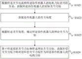
如图1所示,本实施例公开一种主从机器人力反馈的控制方法,所述主从机器人包括协作机器人,所述控制方法包括:As shown in FIG1 , this embodiment discloses a control method for force feedback of a master-slave robot, wherein the master-slave robot includes a collaborative robot, and the control method includes:
步骤S101、获取关节电流;所述关节电流为协作机器人在运动控制下接触到环境力后,生成的电流;Step S101, obtaining joint current; the joint current is the current generated when the collaborative robot contacts the environmental force under motion control;
具体地,协作机器人在运动控制下接触到环境力后,由末端负载产生关节电流。采集的电流变化趋势如图2所示。Specifically, when the collaborative robot is exposed to environmental forces under motion control, joint current is generated by the end load. The collected current change trend is shown in Figure 2.
步骤S102、基于所述关节电流,确定所述协作机器人的电机力矩;Step S102: determining the motor torque of the collaborative robot based on the joint current;
步骤S103、基于所述电机力矩,通过指数缩放的方式将所述电机力矩转化为主控设备的虚拟力矩。Step S103: Based on the motor torque, convert the motor torque into a virtual torque of a main control device by exponential scaling.
本方案中,如图3所示,主从机器人力反馈控制结构包括主控设备(力反馈设备)、工控机、数据采集模块、电机驱动器、解码器和电机。主控设备与工控机相连,工控机内包含运动学模块和动力学模块与数据采集模块相连,数据采集模块与协作机器人相连,协作机器人内部驱动器与解码器相连,解码器与电机相连。其中,即控制系统的主端机器人,能效应人手的运动,用于远程操作协作机器人,可以实时地产生多自由度的虚拟力矩;工控机,实时地发送角度信号至从端机器人,实时地采集从端机器人的关节电机的各项信号;协作机器人,即从端机器人,串联结构具有六自由度,末端具备跟换工具接口,各关节分别设置对应的驱动电机及编码器,用于机器人的运动学控制和信号采集。In this solution, as shown in Figure 3, the master-slave robot force feedback control structure includes a master control device (force feedback device), an industrial computer, a data acquisition module, a motor driver, a decoder and a motor. The master control device is connected to the industrial computer, the kinematics module and the dynamics module contained in the industrial computer are connected to the data acquisition module, the data acquisition module is connected to the collaborative robot, the internal driver of the collaborative robot is connected to the decoder, and the decoder is connected to the motor. Among them, the master robot of the control system can imitate the movement of human hands and is used to remotely operate the collaborative robot, and can generate virtual torques with multiple degrees of freedom in real time; the industrial computer sends angle signals to the slave robot in real time, and collects various signals of the joint motors of the slave robot in real time; the collaborative robot, that is, the slave robot, has a series structure with six degrees of freedom, and the end is equipped with a tool replacement interface. Each joint is respectively provided with a corresponding drive motor and encoder for the robot's kinematic control and signal acquisition.
本方案中,机器人的主从运动控制采取了异构主从控制,如,主控设备采用Omega.7,为混联结构结构,与协作机器人组成异构主从控制。通过力反馈设备开放的SDK采集主端机器人实时的末端位置信息和姿态信息。力反馈设备的工作空间范围Ra mm,而协作机器人的工作范围为Rb mm,如,Omega7的工作空间Ra为Φ160mm,协作机器人的工作空间为Φ1640mm,因此需要按比例转化机器人的位置信息,即:In this solution, the robot's master-slave motion control adopts heterogeneous master-slave control. For example, the master control device adopts Omega.7, which is a hybrid structure, and forms a heterogeneous master-slave control with the collaborative robot. The real-time terminal position information and posture information of the master robot are collected through the SDK open to the force feedback device. The working space range of the force feedback device isRa mm, while the working range of the collaborative robot isRb mm. For example, the working spaceRa of Omega7 is Φ160mm, and the working space of the collaborative robot is Φ1640mm. Therefore, the position information of the robot needs to be converted proportionally, that is:


0Pb为从端机器人末端执行器相对其基座坐标系的位置信息,0Pa为Omega.7末端执行器相对其基座坐标系的位置信息。其中,0Xb、0Yb、0Zb分别为从端机器人末端执行器相对其基座坐标系的X轴、Y轴、Z轴坐标,0Xa、0Ya、0Za分别为主端机器人末端执行器相对其基座坐标系的X轴、Y轴、Z轴坐标。0 Pb is the position information of the slave robot end effector relative to its base coordinate system, and0 Pa is the position information of the Omega.7 end effector relative to its base coordinate system. Among them,0 Xb ,0 Yb ,0 Zb are the X-axis, Y-axis, and Z-axis coordinates of the slave robot end effector relative to its base coordinate system, and0 Xa ,0Ya ,0Za are the X-axis, Y-axis, and Z-axis coordinates of the master robot end effector relative to its base coordinate system.
将力反馈设备的姿态信息直接发送至从端机器人,利用式(2)经转换后得到的从端机器人的齐次变换矩阵0T6为:The posture information of the force feedback device is directly sent to the slave robot. The homogeneous transformation matrix0 T6 of the slave robot obtained by conversion using formula (2) is:

其中0Ra为力反馈设备的末端相对于基座的3x3姿态矩阵。上位机中根据协作机器人的DH参数,建立从端机器人的运动学模型,得出机器人的运动学逆解,将转换得到的姿态矩阵0T6通过逆运动学计算得到从端机器人的各关节转动角度。为从端机器人的各关节设置软限位,范围与主端设备相同,以确保协作机器人在操作过程中不超出工作范围。Where0 Ra is the 3x3 attitude matrix of the end of the force feedback device relative to the base. In the host computer, the kinematic model of the slave robot is established according to the DH parameters of the collaborative robot, and the inverse kinematic solution of the robot is obtained. The converted attitude matrix0 T6 is calculated by inverse kinematics to obtain the rotation angle of each joint of the slave robot. Soft limits are set for each joint of the slave robot, and the range is the same as that of the master device to ensure that the collaborative robot does not exceed the working range during operation.
此外,由于从端机器人的各关节限位远远大于主端机器人,在机器人实施长距离移动时,为了确保从端机器人的在到达指定位置后不需要大幅调整姿态,影响操作执行,因此只采集主端设备的位置信息,将末端工具的姿态设置成保持垂直于地面的状态。In addition, since the joint limits of the slave robot are much larger than those of the master robot, when the robot moves long distances, in order to ensure that the slave robot does not need to adjust its posture significantly after reaching the specified position, which will affect the execution of the operation, only the position information of the master device is collected, and the posture of the end tool is set to remain perpendicular to the ground.
本方案中,工控机实时的发送上位机计算出的关节角度至协作机器人,并采集协作机器人的各关节的角度信号,协作机器人的各项参数由电机驱动器获取,旋转编码器将转动关节的脉冲数转化成角度信号,将采集到的从端In this solution, the industrial computer sends the joint angle calculated by the host computer to the collaborative robot in real time, and collects the angle signals of each joint of the collaborative robot. The various parameters of the collaborative robot are obtained by the motor driver. The rotary encoder converts the pulse number of the rotating joint into an angle signal.
机器人的关节电机当前角度q和上位机计算期望角度


上位机实时地通过补偿该误差实现角度闭环控制,提高了从端机器人的主从运动控制的实时控制精度。The host computer realizes angle closed-loop control by compensating the error in real time, thereby improving the real-time control accuracy of the master-slave motion control of the slave robot.
工控机实时地采集关节电机电流信号,将采集到的信号发送至上位机,为了减少关节电机与减速器间的摩擦、外界振动等干扰,对每个时刻的电流信号进行卡尔曼滤波处理。The industrial computer collects the joint motor current signal in real time and sends the collected signal to the host computer. In order to reduce the friction between the joint motor and the reducer, external vibration and other interference, the current signal at each moment is processed by Kalman filtering.
本方案,通过指数缩放的方式将电机力矩转化为主控设备的虚拟力矩,既保证了主从机器人力反馈的控制的准确度,也保证主端力反馈设备的虚拟力矩值不超过预设阈值。进而避免了力反馈设备导致力矩过大影响用户操作的问题,提升了用户操作时的安全性和舒适度。This solution converts the motor torque into the virtual torque of the master control device by exponential scaling, which not only ensures the accuracy of the force feedback control of the master and slave robots, but also ensures that the virtual torque value of the master force feedback device does not exceed the preset threshold. This avoids the problem of excessive torque caused by the force feedback device affecting user operation, and improves the safety and comfort of user operation.
在一可实施的方式,所述步骤S102具体包括:In one practicable manner, step S102 specifically includes:
根据所述关节电流和所述协作机器人的电机力矩的关联关系,获取所述协作机器人的实际关节力矩,并将所述实际关节力矩直接作为所述协作机器人的电机力矩。According to the correlation between the joint current and the motor torque of the collaborative robot, the actual joint torque of the collaborative robot is obtained, and the actual joint torque is directly used as the motor torque of the collaborative robot.
如图4所示,在一可实施的方式中,所述步骤S102包括:As shown in FIG. 4 , in one practicable manner, step S102 includes:
步骤S1021、根据所述关节电流和所述协作机器人的电机力矩的关联关系,获取所述协作机器人的实际关节力矩;Step S1021, acquiring the actual joint torque of the collaborative robot according to the correlation relationship between the joint current and the motor torque of the collaborative robot;
步骤S1022、获取协作机器人的关节角度;Step S1022, obtaining the joint angles of the collaborative robot;
步骤S1023、根据所述关节角度,确定所述协作机器人的理论关节力矩;Step S1023, determining the theoretical joint torque of the collaborative robot according to the joint angle;
步骤S1024、基于所述实际关节力矩和所述理论关节力矩,获取补偿关节力矩并将所述补偿关节力矩作为所述协作机器人的电机力矩。Step S1024: Based on the actual joint torque and the theoretical joint torque, obtain the compensated joint torque and use the compensated joint torque as the motor torque of the collaborative robot.
具体地,主从机器人力反馈控制结构中的上位机将获取从端机器人的实时角度和电流信号,为实现关节力反馈,需建立主手关节力矩和伺服电机输出力矩之间的对应关系。对于直流无刷电机,其电机反电动势常数的计算公式:Specifically, the host computer in the master-slave robot force feedback control structure will obtain the real-time angle and current signal of the slave robot. In order to realize joint force feedback, it is necessary to establish the corresponding relationship between the master hand joint torque and the servo motor output torque. For a brushless DC motor, the calculation formula for its motor back electromotive force constant is:
Kv≈9.55*I/τ(5)Kv ≈9.55*I/τ(5)
其中,τ为电机输出转矩,I为电机电流。Kv指电机的反电动势常数,它的定义为:输入电压每增加1V,直流无刷电机空载转速增加的值。通过逆动力学模块估计出从端机器人的各关节力矩。估计得到的关节电机力矩为

其中K为运动学回归矩阵,Φ为动力学参数集。根据式(6)可以得到力矩误差

通过式(7)对每个时刻的力矩误差进行补偿,提高动力学模型精度,提高力反馈控制精度。The torque error at each moment is compensated by formula (7), which improves the accuracy of the dynamic model and the accuracy of force feedback control.
本方案,通过采集电流计算协作机器人的电机力矩实际关节力矩,在工控机内通过动力学模块计算估计出协作机器人的理论关节力矩,实现电机力矩补偿,从而进一步提高了主从机器人力反馈的控制的准确度。This solution calculates the actual joint torque of the collaborative robot's motor torque by collecting current, and estimates the theoretical joint torque of the collaborative robot through the dynamics module in the industrial computer to achieve motor torque compensation, thereby further improving the accuracy of the force feedback control of the master-slave robot.
在一可实施的方式中,所述基于所述电机力矩,通过指数缩放的方式将电机力矩转化为主控设备的虚拟力矩的步骤包括:In an practicable manner, the step of converting the motor torque into a virtual torque of a main control device by exponential scaling based on the motor torque includes:
基于所述电机力矩,采用了反指数函数将电机力矩转化为主控设备的虚拟力矩。Based on the motor torque, an inverse exponential function is used to convert the motor torque into a virtual torque of a main control device.
具体地,将力反馈设备的虚拟力矩不超过aN·m,采用了反指数函数,经过处理后的力反馈设备关节力矩τ′:Specifically, the virtual torque of the force feedback device is set to no more than aN·m, and an inverse exponential function is used. The processed joint torque τ′ of the force feedback device is:
τ′=a×(1-e-τ/k) (8)τ′=a×(1-e-τ/k ) (8)
在一具体的实施例中,假设需将力反馈设备的虚拟力矩不超过2N·m,采用了反指数函数,经过处理后的力反馈设备关节力矩τ′:In a specific embodiment, assuming that the virtual torque of the force feedback device needs to be no more than 2 N·m, an inverse exponential function is used, and the processed joint torque τ′ of the force feedback device is:
τ′=2×(1-e-τ/k)τ′=2×(1-e-τ/k )
其中,k表征关节电机力矩缩放系数,为关节电机最大扭矩参数与力反馈设备可产生的最大力矩的比值。Among them, k represents the joint motor torque scaling factor, which is the ratio of the maximum torque parameter of the joint motor to the maximum torque that the force feedback device can generate.
对式(8)求导得到:By taking the derivative of formula (8), we can get:

由式(9)可知,力反馈设备的导数为单调减函数,因此从端机器人接收到的力越大,则主端力反馈设备的力的变化量就越小,充分保证用户的使用安全性。It can be seen from formula (9) that the derivative of the force feedback device is a monotonically decreasing function. Therefore, the greater the force received by the slave robot, the smaller the change in the force of the master force feedback device, which fully ensures the user's safety.
在一具体的实施例中,采用的关节电机中的反电动势常数Kv为78.4,最大扭矩为5.65N·m,力反馈设备的最大力矩为2N·m,则力矩的比例系数为2.825。图5,为经指数函数处理后的力反馈曲线,可以看到力矩曲线的变化趋势与电流相匹配,且力矩不超过2N·m,能够保证用户安全。然而,图6为经比例函数转化后的力反馈曲线,从图中可以看到力矩与电流的变化趋势相匹配,但部分力矩超过了2N·m,无法保证安全型,且不满足力反馈设备的实例力矩范围。In a specific embodiment, the back electromotive force constant Kv in the joint motor used is 78.4, the maximum torque is 5.65N·m, and the maximum torque of the force feedback device is 2N·m, then the proportional coefficient of the torque is 2.825. Figure 5 is the force feedback curve after being processed by the exponential function. It can be seen that the change trend of the torque curve matches the current, and the torque does not exceed 2N·m, which can ensure user safety. However, Figure 6 is the force feedback curve after being converted by the proportional function. It can be seen from the figure that the torque matches the change trend of the current, but some of the torque exceeds 2N·m, and the safety cannot be guaranteed, and the example torque range of the force feedback device is not met.
本方案,采用了反指数函数将电机力矩转化为主控设备的虚拟力矩保证了主端力反馈设备的虚拟力矩值不超过预设阈值,从而避免了力反馈设备导致力矩过大影响用户操作的问题,提升了用户操作时的安全性和舒适度。This solution uses an inverse exponential function to convert the motor torque into the virtual torque of the main control device to ensure that the virtual torque value of the main-end force feedback device does not exceed the preset threshold, thereby avoiding the problem of excessive torque caused by the force feedback device affecting user operation and improving the safety and comfort of the user during operation.
实施例2Example 2
如图7所示,本实施例公开了一种主从机器人力反馈的控制系统,所述控制系统包括:As shown in FIG7 , this embodiment discloses a control system for force feedback of a master-slave robot, the control system comprising:
获取模块1,用于获取关节电流;所述关节电流为协作机器人在运动控制下接触到环境力后,生成的关节电流;An
具体地,协作机器人在运动控制下接触到环境力后,由末端负载产生关节电流。采集的电流变化趋势如图2所示。Specifically, when the collaborative robot is exposed to environmental forces under motion control, joint current is generated by the end load. The collected current change trend is shown in Figure 2.
力矩确定模块2,用于获取基于所述关节电流,确定所述协作机器人的电机力矩;A
转换模块3,用于基于所述电机力矩,通过指数缩放的方式将电机力矩转化为主控设备的虚拟力矩。The conversion module 3 is used to convert the motor torque into a virtual torque of the main control device through exponential scaling based on the motor torque.
本方案中,如图3所示,主从机器人力反馈控制结构包括主控设备(力反馈设备)、工控机、数据采集模块、电机驱动器、解码器和电机。主控设备与工控机相连,工控机内包含运动学模块和动力学模块与数据采集模块相连,数据采集模块与协作机器人相连,协作机器人内部驱动器与解码器相连,解码器与电机相连。其中,即控制系统的主端机器人,能效应人手的运动,用于远程操作协作机器人,可以实时地产生多自由度的虚拟力矩;工控机,实时地发送角度信号至从端机器人,实时地采集从端机器人的关节电机的各项信号;协作机器人,即从端机器人,串联结构具有六自由度,末端具备跟换工具接口,各关节分别设置对应的驱动电机及编码器,用于机器人的运动学控制和信号采集。In this solution, as shown in Figure 3, the master-slave robot force feedback control structure includes a master control device (force feedback device), an industrial computer, a data acquisition module, a motor driver, a decoder and a motor. The master control device is connected to the industrial computer, the kinematics module and the dynamics module contained in the industrial computer are connected to the data acquisition module, the data acquisition module is connected to the collaborative robot, the internal driver of the collaborative robot is connected to the decoder, and the decoder is connected to the motor. Among them, the master robot of the control system can imitate the movement of human hands and is used to remotely operate the collaborative robot, and can generate virtual torques with multiple degrees of freedom in real time; the industrial computer sends angle signals to the slave robot in real time, and collects various signals of the joint motors of the slave robot in real time; the collaborative robot, that is, the slave robot, has a series structure with six degrees of freedom, and the end is equipped with a tool replacement interface. Each joint is respectively provided with a corresponding drive motor and encoder for the robot's kinematic control and signal acquisition.
本方案中,机器人的主从运动控制采取了异构主从控制,如,主控设备采用Omega.7,为混联结构结构,与协作机器人组成异构主从控制。通过力反馈设备开放的SDK采集主端机器人实时的末端位置信息和姿态信息。力反馈设备的工作空间范围Ra mm,而协作机器人的工作范围为Rb mm,如,Omega7的工作空间Ra为Φ160mm,协作机器人的工作空间为Φ1640mm,因此需要按比例转化机器人的位置信息,即:In this solution, the robot's master-slave motion control adopts heterogeneous master-slave control. For example, the master control device adopts Omega.7, which is a hybrid structure, and forms a heterogeneous master-slave control with the collaborative robot. The real-time terminal position information and posture information of the master robot are collected through the SDK open to the force feedback device. The working space range of the force feedback device isRa mm, while the working range of the collaborative robot isRb mm. For example, the working spaceRa of Omega7 is Φ160mm, and the working space of the collaborative robot is Φ1640mm. Therefore, the position information of the robot needs to be converted proportionally, that is:


其中0Pb为从端机器人末端执行器相对基座的位置信息,0Pa为Omega.7末端执行器相对基座的位置信息。Where0 Pb is the position information of the end effector of the slave robot relative to the base, and0 Pa is the position information of the end effector of Omega.7 relative to the base.
将力反馈设备的姿态信息直接发送至从端机器人,利用式(2)经转换后得到的从端机器人的齐次变换矩阵0T6为:The posture information of the force feedback device is directly sent to the slave robot. The homogeneous transformation matrix0 T6 of the slave robot obtained by conversion using formula (2) is:

其中0Ra为力反馈设备的末端相对于基座的3x3姿态矩阵。上位机中根据协作机器人的DH参数,建立从端机器人的运动学模型,得出机器人的运动学逆解,将转换得到的姿态矩阵0T6通过逆运动学计算得到从端机器人的各关节转动角度。为从端机器人的各关节设置软限位,范围与主端设备相同,以确保协作机器人在操作过程中不超出工作范围。Where0 Ra is the 3x3 attitude matrix of the end of the force feedback device relative to the base. In the host computer, the kinematic model of the slave robot is established according to the DH parameters of the collaborative robot, and the inverse kinematic solution of the robot is obtained. The converted attitude matrix0 T6 is calculated by inverse kinematics to obtain the rotation angle of each joint of the slave robot. Soft limits are set for each joint of the slave robot, and the range is the same as that of the master device to ensure that the collaborative robot does not exceed the working range during operation.
此外,由于从端机器人的各关节限位远远大于主端机器人,在机器人实施长距离移动时,为了确保从端机器人的在到达指定位置后不需要大幅调整姿态,影响操作执行,因此只采集主端设备的位置信息,将末端工具的姿态设置成保持垂直于地面的状态。In addition, since the joint limits of the slave robot are much larger than those of the master robot, when the robot moves long distances, in order to ensure that the slave robot does not need to adjust its posture significantly after reaching the specified position, which will affect the execution of the operation, only the position information of the master device is collected, and the posture of the end tool is set to remain perpendicular to the ground.
本方案中,工控机实时的发送上位机计算出的关节角度至协作机器人,并采集协作机器人的各关节的角度信号,协作机器人的各项参数由电机驱动器获取,旋转编码器将转动关节的脉冲数转化成角度信号,将采集到的从端机器人的关节电机当前角度q和上位机计算期望角度


上位机实时地通过补偿该误差实现角度闭环控制,提高了从端机器人的主从运动控制的实时控制精度。The host computer realizes angle closed-loop control by compensating the error in real time, thereby improving the real-time control accuracy of the master-slave motion control of the slave robot.
工控机实时地采集关节电机电流信号,将采集到的信号发送至上位机,为了减少关节电机与减速器间的摩擦、外界振动等干扰,对每个时刻的电流信号进行卡尔曼滤波处理。The industrial computer collects the joint motor current signal in real time and sends the collected signal to the host computer. In order to reduce the friction between the joint motor and the reducer, external vibration and other interference, the current signal at each moment is processed by Kalman filtering.
本方案,通过指数缩放的方式将电机力矩转化为主控设备的虚拟力矩,既保证了主从机器人力反馈的控制的准确度,也保证主端力反馈设备的虚拟力矩值不超过预设阈值。进而,避免了力反馈设备导致力矩过大影响用户操作的问题,提升了用户操作时的安全性和舒适度。This solution converts the motor torque into the virtual torque of the master control device by exponential scaling, which not only ensures the accuracy of the force feedback control of the master and slave robots, but also ensures that the virtual torque value of the master force feedback device does not exceed the preset threshold. In addition, it avoids the problem of excessive torque caused by the force feedback device affecting user operation, and improves the safety and comfort of user operation.
在一可实施的方式中,所述力矩确定模块2具体用于:In an practicable manner, the
根据所述关节电流和所述协作机器人的电机力矩的关联关系,获取所述协作机器人的实际关节力矩,并将所述实际关节力矩直接作为所述协作机器人的电机力矩。According to the correlation between the joint current and the motor torque of the collaborative robot, the actual joint torque of the collaborative robot is obtained, and the actual joint torque is directly used as the motor torque of the collaborative robot.
如图8所示,在一可实施的方式中,所述基于所述力矩确定模块2包括:As shown in FIG8 , in an exemplified manner, the torque-based
第一获取单元21,用于根据所述关节电流和所述协作机器人的电机力矩的关联关系,获取所述协作机器人的实际关节力矩;A
第二获取单元22,用于获取协作机器人的关节角度;A
力矩确定单元23,用于根据所述关节角度,确定所述协作机器人的理论关节力矩;A
第三获取单元24,用于基于所述实际关节力矩和所述理论关节力矩,获取补偿关节力矩并将所述补偿关节力矩作为所述协作机器人的电机力矩。The
具体地,主从机器人力反馈控制结构中的上位机将获取从端机器人的实时角度和电流信号,为实现关节力反馈,需建立主手关节力矩和伺服电机输出力矩之间的对应关系。对于直流无刷电机,其电机反电动势常数的计算公式:Specifically, the host computer in the master-slave robot force feedback control structure will obtain the real-time angle and current signal of the slave robot. In order to realize joint force feedback, it is necessary to establish the corresponding relationship between the master hand joint torque and the servo motor output torque. For a brushless DC motor, the calculation formula for its motor back electromotive force constant is:
Kv≈9.55*I/τ(5)Kv ≈9.55*I/τ(5)
其中,τ为电机输出转矩,I为电机电流。Kv指电机的反电动势常数,它的定义为:输入电压每增加1V,直流无刷电机空载转速增加的值。通过逆动力学模块估计出从端机器人的各关节力矩。估计得到的关节电机力矩为

其中K为运动学回归矩阵,Φ为动力学参数集。根据式(6)可以得到力矩误差

通过式(7)对每个时刻的力矩误差进行补偿,提高动力学模型精度,提高力反馈控制精度。The torque error at each moment is compensated by formula (7), which improves the accuracy of the dynamic model and the accuracy of force feedback control.
本方案,通过采集电流计算协作机器人的电机力矩实际关节力矩,在工控机内通过动力学模块计算估计出协作机器人的理论关节力矩,实现电机力矩补偿,从而进一步提高了主从机器人力反馈的控制的准确度。This solution calculates the actual joint torque of the collaborative robot's motor torque by collecting current, and estimates the theoretical joint torque of the collaborative robot through the dynamics module in the industrial computer to achieve motor torque compensation, thereby further improving the accuracy of the force feedback control of the master-slave robot.
在一可实施的方式中,所述转换模块3具体用于:In an practicable manner, the conversion module 3 is specifically used for:
基于所述电机力矩,采用了反指数函数将电机力矩转化为主控设备的虚拟力矩。Based on the motor torque, an inverse exponential function is used to convert the motor torque into a virtual torque of a main control device.
具体地,将力反馈设备的虚拟力矩不超过aN·m,采用了反指数函数,经过处理后的力反馈设备关节力矩τ′:Specifically, the virtual torque of the force feedback device is set to no more than aN·m, and an inverse exponential function is used. The processed joint torque τ′ of the force feedback device is:
τ′=a×(1-e-τ/k) (8)τ′=a×(1-e-τ/k ) (8)
在一具体的实施例中,假设需将力反馈设备的虚拟力矩不超过2N·m,采用了反指数函数,经过处理后的力反馈设备关节力矩τ′:In a specific embodiment, assuming that the virtual torque of the force feedback device needs to be no more than 2 N·m, an inverse exponential function is used, and the processed joint torque τ′ of the force feedback device is:
τ′=2×(1-e-τ/k)τ′=2×(1-e-τ/k )
其中,k表征关节电机力矩缩放系数,为关节电机最大扭矩参数与力反馈设备可产生的最大力矩的比值。Among them, k represents the joint motor torque scaling factor, which is the ratio of the maximum torque parameter of the joint motor to the maximum torque that the force feedback device can generate.
对式(8)求导得到:By taking the derivative of formula (8), we can get:

由式(9)可知,力反馈设备的导数为单调减函数,因此从端机器人接收到的力越大,则主端力反馈设备的力的变化量就越小,充分保证用户的使用安全性。It can be seen from formula (9) that the derivative of the force feedback device is a monotonically decreasing function. Therefore, the greater the force received by the slave robot, the smaller the change in the force of the master force feedback device, which fully ensures the user's safety.
在一具体的实施例中,采用的关节电机中的反电动势常数Kv为78.4,最大扭矩为5.65N·m,力反馈设备的最大力矩为2N·m,则力矩的比例系数为2.825。图5,为经指数函数处理后的力反馈曲线,可以看到力矩曲线的变化趋势与电流相匹配,且力矩不超过2N·m,能够保证用户安全。然而,图6为经比例函数转化后的力反馈曲线,从图中可以看到力矩与电流的变化趋势相匹配,但部分力矩超过了2N·m,无法保证安全型,且不满足力反馈设备的实例力矩范围。In a specific embodiment, the back electromotive force constant Kv in the joint motor used is 78.4, the maximum torque is 5.65N·m, and the maximum torque of the force feedback device is 2N·m, then the proportional coefficient of the torque is 2.825. Figure 5 is the force feedback curve after being processed by the exponential function. It can be seen that the change trend of the torque curve matches the current, and the torque does not exceed 2N·m, which can ensure user safety. However, Figure 6 is the force feedback curve after being converted by the proportional function. It can be seen from the figure that the torque matches the change trend of the current, but some of the torque exceeds 2N·m, and the safety cannot be guaranteed, and the example torque range of the force feedback device is not met.
本方案,采用了反指数函数将电机力矩转化为主控设备的虚拟力矩保证了主端力反馈设备的虚拟力矩值不超过预设阈值,从而避免了力反馈设备导致力矩过大影响用户操作的问题,提升了用户操作时的安全性和舒适度。This solution uses an inverse exponential function to convert the motor torque into the virtual torque of the main control device, ensuring that the virtual torque value of the main-end force feedback device does not exceed the preset threshold, thereby avoiding the problem of excessive torque caused by the force feedback device affecting user operation and improving the safety and comfort of user operation.
实施例3Example 3
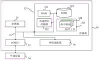
图9为本发明实施例3提供的一种电子设备的结构示意图。所述电子设备包括存储器、处理器及存储在存储器上并用于在处理器上运行的计算机程序,所述处理器执行所述程序时实现实施例1所提供的主从机器人力反馈的控制方法。图9显示的电子设备30仅仅是一个示例,不应对本发明实施例的功能和使用范围带来任何限制。FIG9 is a schematic diagram of the structure of an electronic device provided in Example 3 of the present invention. The electronic device includes a memory, a processor, and a computer program stored in the memory and used to run on the processor. When the processor executes the program, the control method of the master-slave robot force feedback provided in Example 1 is implemented. The
如图9所示,电子设备30可以以通用计算设备的形式表现,例如其可以为服务器设备。电子设备30的组件可以包括但不限于:上述至少一个处理器31、上述至少一个存储器32、连接不同系统组件(包括存储器32和处理器31)的总线33。As shown in Fig. 9, the
总线33包括数据总线、地址总线和控制总线。The
存储器32可以包括易失性存储器,例如随机存取存储器(RAM)321和/或高速缓存存储器322,还可以进一步包括只读存储器(ROM)323。The
存储器32还可以包括具有一组(至少一个)程序模块324的程序/实用工具325,这样的程序模块324包括但不限于:操作系统、一个或者多个应用程序、其它程序模块以及程序数据,这些示例中的每一个或某种组合中可能包括网络环境的实现。The
处理器31通过运行存储在存储器32中的计算机程序,从而执行各种功能应用以及数据处理,例如本发明实施例1所提供的主从机器人力反馈的控制方法。The
电子设备30也可以与一个或多个外部设备34(例如键盘、指向设备等)通信。这种通信可以通过输入/输出(I/O)接口35进行。并且,模型生成的设备30还可以通过网络适配器36与一个或者多个网络(例如局域网(LAN),广域网(WAN)和/或公共网络,例如因特网)通信。如图所示,网络适配器36通过总线33与模型生成的设备30的其它模块通信。应当明白,尽管图中未示出,可以结合模型生成的设备30使用其它硬件和/或软件模块,包括但不限于:微代码、设备驱动器、冗余处理器、外部磁盘驱动阵列、RAID(磁盘阵列)系统、磁带驱动器以及数据备份存储系统等。The
应当注意,尽管在上文详细描述中提及了电子设备的若干单元/模块或子单元/模块,但是这种划分仅仅是示例性的并非强制性的。实际上,根据本发明的实施方式,上文描述的两个或更多单元/模块的特征和功能可以在一个单元/模块中具体化。反之,上文描述的一个单元/模块的特征和功能可以进一步划分为由多个单元/模块来具体化。It should be noted that although several units/modules or sub-units/modules of the electronic device are mentioned in the above detailed description, this division is merely exemplary and not mandatory. In fact, according to an embodiment of the present invention, the features and functions of two or more units/modules described above can be embodied in one unit/module. Conversely, the features and functions of one unit/module described above can be further divided into multiple units/modules to be embodied.
实施例4Example 4
本实施例提供了一种计算机可读存储介质,其上存储有计算机程序,所述程序被处理器执行时实现实施例1所提供的主从机器人力反馈的控制方法的步骤。This embodiment provides a computer-readable storage medium on which a computer program is stored. When the program is executed by a processor, the steps of the control method for force feedback of the master-slave robot provided in
其中,可读存储介质可以采用的更具体可以包括但不限于:便携式盘、硬盘、随机存取存储器、只读存储器、可擦拭可编程只读存储器、光存储器件、磁存储器件或上述的任意合适的组合。The readable storage medium may include but is not limited to: a portable disk, a hard disk, a random access memory, a read-only memory, an erasable programmable read-only memory, an optical storage device, a magnetic storage device or any suitable combination of the above.
在可能的实施方式中,本发明还可以实现为一种程序产品的形式,其包括程序代码,当所述程序产品在终端设备上运行时,所述程序代码用于使所述终端设备执行实现实施例1所提供的主从机器人力反馈的控制方法中的步骤。In a possible implementation, the present invention can also be implemented in the form of a program product, which includes a program code. When the program product is run on a terminal device, the program code is used to enable the terminal device to execute the steps in the control method for master-slave robot force feedback provided in Example 1.
其中,可以以一种或多种程序设计语言的任意组合来编写用于执行本发明的程序代码,所述程序代码可以完全地在用户设备上执行、部分地在用户设备上执行、作为一个独立的软件包执行、部分在用户设备上部分在远程设备上执行或完全在远程设备上执行。The program code for executing the present invention may be written in any combination of one or more programming languages, and may be executed entirely on a user device, partially on a user device, as an independent software package, partially on a user device and partially on a remote device, or entirely on a remote device.
虽然以上描述了本发明的具体实施方式,但是本领域的技术人员应当理解,这仅是举例说明,本发明的保护范围是由所附权利要求书限定的。本领域的技术人员在不背离本发明的原理和实质的前提下,可以对这些实施方式做出多种变更或修改,但这些变更和修改均落入本发明的保护范围。Although the specific embodiments of the present invention are described above, it should be understood by those skilled in the art that this is only for illustration and the protection scope of the present invention is defined by the appended claims. Those skilled in the art may make various changes or modifications to these embodiments without departing from the principles and essence of the present invention, but these changes and modifications all fall within the protection scope of the present invention.
Claims (10)
Priority Applications (1)
| Application Number | Priority Date | Filing Date | Title |
|---|---|---|---|
| CN202310103309.2ACN116079733A (en) | 2023-02-10 | 2023-02-10 | Master-slave robot manpower feedback control method, system, equipment and medium |
Applications Claiming Priority (1)
| Application Number | Priority Date | Filing Date | Title |
|---|---|---|---|
| CN202310103309.2ACN116079733A (en) | 2023-02-10 | 2023-02-10 | Master-slave robot manpower feedback control method, system, equipment and medium |
Publications (1)
| Publication Number | Publication Date |
|---|---|
| CN116079733Atrue CN116079733A (en) | 2023-05-09 |
Family
ID=86200642
Family Applications (1)
| Application Number | Title | Priority Date | Filing Date |
|---|---|---|---|
| CN202310103309.2APendingCN116079733A (en) | 2023-02-10 | 2023-02-10 | Master-slave robot manpower feedback control method, system, equipment and medium |
Country Status (1)
| Country | Link |
|---|---|
| CN (1) | CN116079733A (en) |
Cited By (1)
| Publication number | Priority date | Publication date | Assignee | Title |
|---|---|---|---|---|
| CN119347766A (en)* | 2024-11-20 | 2025-01-24 | 南京航空航天大学 | Teleoperation method of mobile manipulator for lunar exploration based on single master-end adaptive switching |
Citations (10)
| Publication number | Priority date | Publication date | Assignee | Title |
|---|---|---|---|---|
| US20120029529A1 (en)* | 2010-07-30 | 2012-02-02 | Lg Electronics Inc. | Medical robotic system and method of controlling the same |
| CN102528790A (en)* | 2010-12-10 | 2012-07-04 | 上海理工大学 | Calligraphy robot system based on force feedback |
| WO2017033353A1 (en)* | 2015-08-25 | 2017-03-02 | 川崎重工業株式会社 | Remote control robot system |
| CN106945043A (en)* | 2017-04-18 | 2017-07-14 | 中国科学院重庆绿色智能技术研究院 | A kind of master-slave mode telesurgery robot multi-arm cooperative control system |
| CN109223444A (en)* | 2018-10-23 | 2019-01-18 | 上海电气集团股份有限公司 | Healing robot and its man-machine coordination interaction force control method |
| CN110035871A (en)* | 2016-11-10 | 2019-07-19 | 康格尼博提克斯股份公司 | The system and method for being used to indicate robot |
| CN112894821A (en)* | 2021-01-30 | 2021-06-04 | 同济大学 | Current method based collaborative robot dragging teaching control method, device and equipment |
| DE102021133638A1 (en)* | 2020-12-31 | 2022-06-30 | Nvidia Corporation | IMAGE COMPOSITION IN MULTI-VIEW AUTOMOTIVE SYSTEMS AND ROBOT SYSTEMS |
| CN115016645A (en)* | 2022-06-15 | 2022-09-06 | 哈尔滨工业大学 | Multi-degree-of-freedom acquired data glove for cooperative control of artificial fingers |
| CN115284319A (en)* | 2022-08-22 | 2022-11-04 | 北京航空航天大学 | Control method of manual control equipment and manual controller |
- 2023
- 2023-02-10CNCN202310103309.2Apatent/CN116079733A/enactivePending
Patent Citations (10)
| Publication number | Priority date | Publication date | Assignee | Title |
|---|---|---|---|---|
| US20120029529A1 (en)* | 2010-07-30 | 2012-02-02 | Lg Electronics Inc. | Medical robotic system and method of controlling the same |
| CN102528790A (en)* | 2010-12-10 | 2012-07-04 | 上海理工大学 | Calligraphy robot system based on force feedback |
| WO2017033353A1 (en)* | 2015-08-25 | 2017-03-02 | 川崎重工業株式会社 | Remote control robot system |
| CN110035871A (en)* | 2016-11-10 | 2019-07-19 | 康格尼博提克斯股份公司 | The system and method for being used to indicate robot |
| CN106945043A (en)* | 2017-04-18 | 2017-07-14 | 中国科学院重庆绿色智能技术研究院 | A kind of master-slave mode telesurgery robot multi-arm cooperative control system |
| CN109223444A (en)* | 2018-10-23 | 2019-01-18 | 上海电气集团股份有限公司 | Healing robot and its man-machine coordination interaction force control method |
| DE102021133638A1 (en)* | 2020-12-31 | 2022-06-30 | Nvidia Corporation | IMAGE COMPOSITION IN MULTI-VIEW AUTOMOTIVE SYSTEMS AND ROBOT SYSTEMS |
| CN112894821A (en)* | 2021-01-30 | 2021-06-04 | 同济大学 | Current method based collaborative robot dragging teaching control method, device and equipment |
| CN115016645A (en)* | 2022-06-15 | 2022-09-06 | 哈尔滨工业大学 | Multi-degree-of-freedom acquired data glove for cooperative control of artificial fingers |
| CN115284319A (en)* | 2022-08-22 | 2022-11-04 | 北京航空航天大学 | Control method of manual control equipment and manual controller |
Non-Patent Citations (2)
| Title |
|---|
| 孟庆鑫等: "机器人技术基础", vol. 1, 30 September 2006, 哈尔滨工业大学出版社, pages: 167* |
| 邓泽;石运永;谢叻;: "腹腔微创手术机器人主从运动及力反馈控制", 机械设计与研究, no. 05, 20 October 2017 (2017-10-20), pages 49 - 53* |
Cited By (1)
| Publication number | Priority date | Publication date | Assignee | Title |
|---|---|---|---|---|
| CN119347766A (en)* | 2024-11-20 | 2025-01-24 | 南京航空航天大学 | Teleoperation method of mobile manipulator for lunar exploration based on single master-end adaptive switching |
Similar Documents
| Publication | Publication Date | Title |
|---|---|---|
| CN106003034B (en) | A kind of robot controller control system and control method | |
| CN106945043B (en) | A multi-arm collaborative control system for a master-slave teleoperated surgical robot | |
| CN101592951B (en) | General Control System of Distributed Humanoid Robot | |
| CN108015763B (en) | An anti-noise interference redundant manipulator path planning method | |
| US9221172B2 (en) | Constraining robotic manipulators with redundant degrees of freedom | |
| CN109968361B (en) | A variable impedance remote operation control device and method based on real-time force feedback | |
| CN114571469B (en) | Zero-space real-time obstacle avoidance control method and system for mechanical arm | |
| NL2026115B1 (en) | Ethercat-based control system for high efficiency and real-time performance of single leg of robot | |
| US11654557B2 (en) | Direct force feedback control method, and controller and robot using the same | |
| CN112720460B (en) | Robot control method, device, computer readable storage medium and robot | |
| WO2007127723A2 (en) | Control of robots from human motion descriptors | |
| CN116079733A (en) | Master-slave robot manpower feedback control method, system, equipment and medium | |
| CN111113429B (en) | Action simulation method, action simulation device and terminal equipment | |
| CN112428263B (en) | Manipulator control method, device and clustering model training method | |
| CN118636129A (en) | Serial robot and its inverse kinematics solution method, related media and equipment | |
| CN120023818A (en) | Robotic arm control method, device, electronic device and computer readable storage medium | |
| CN118493407B (en) | Human-machine collaborative safety control method and device based on mixed reality and digital twin | |
| Peer et al. | Towards a mobile haptic interface for bimanual manipulations | |
| CN116423523A (en) | Flexible control method and system for master-slave robot, electronic equipment and storage medium | |
| CN109773792B (en) | Position control device and method for serial elastic drive, storage medium and device | |
| CN118123830A (en) | Super redundant manipulator motion planning method and system based on improved zero space optimization | |
| CN114750153B (en) | Motion control system for robot arm, cooperative robot and storage medium | |
| CN117085301A (en) | Multi-feedback rehabilitation training method and system for rehabilitation robots based on virtual reality | |
| CN114505849A (en) | Robot control device and robot control method | |
| CN116252298A (en) | Remote operation method and system for robot based on force feedback technology |
Legal Events
| Date | Code | Title | Description |
|---|---|---|---|
| PB01 | Publication | ||
| PB01 | Publication | ||
| SE01 | Entry into force of request for substantive examination | ||
| SE01 | Entry into force of request for substantive examination |