CN116078596A - Vacuum spraying equipment - Google Patents
Vacuum spraying equipmentDownload PDFInfo
- Publication number
- CN116078596A CN116078596ACN202310105669.6ACN202310105669ACN116078596ACN 116078596 ACN116078596 ACN 116078596ACN 202310105669 ACN202310105669 ACN 202310105669ACN 116078596 ACN116078596 ACN 116078596A
- Authority
- CN
- China
- Prior art keywords
- dust cover
- spraying equipment
- cover
- casing
- workpiece
- Prior art date
- Legal status (The legal status is an assumption and is not a legal conclusion. Google has not performed a legal analysis and makes no representation as to the accuracy of the status listed.)
- Pending
Links
Images

Classifications
- B—PERFORMING OPERATIONS; TRANSPORTING
- B05—SPRAYING OR ATOMISING IN GENERAL; APPLYING FLUENT MATERIALS TO SURFACES, IN GENERAL
- B05B—SPRAYING APPARATUS; ATOMISING APPARATUS; NOZZLES
- B05B16/00—Spray booths
- B05B16/40—Construction elements specially adapted therefor, e.g. floors, walls or ceilings
- B—PERFORMING OPERATIONS; TRANSPORTING
- B05—SPRAYING OR ATOMISING IN GENERAL; APPLYING FLUENT MATERIALS TO SURFACES, IN GENERAL
- B05B—SPRAYING APPARATUS; ATOMISING APPARATUS; NOZZLES
- B05B12/00—Arrangements for controlling delivery; Arrangements for controlling the spray area
- B05B12/16—Arrangements for controlling delivery; Arrangements for controlling the spray area for controlling the spray area
- B05B12/32—Shielding elements, i.e. elements preventing overspray from reaching areas other than the object to be sprayed
- B—PERFORMING OPERATIONS; TRANSPORTING
- B05—SPRAYING OR ATOMISING IN GENERAL; APPLYING FLUENT MATERIALS TO SURFACES, IN GENERAL
- B05B—SPRAYING APPARATUS; ATOMISING APPARATUS; NOZZLES
- B05B14/00—Arrangements for collecting, re-using or eliminating excess spraying material
- B05B14/40—Arrangements for collecting, re-using or eliminating excess spraying material for use in spray booths
- B05B14/48—Arrangements for collecting, re-using or eliminating excess spraying material for use in spray booths specially adapted for particulate material
- H—ELECTRICITY
- H10—SEMICONDUCTOR DEVICES; ELECTRIC SOLID-STATE DEVICES NOT OTHERWISE PROVIDED FOR
- H10F—INORGANIC SEMICONDUCTOR DEVICES SENSITIVE TO INFRARED RADIATION, LIGHT, ELECTROMAGNETIC RADIATION OF SHORTER WAVELENGTH OR CORPUSCULAR RADIATION
- H10F71/00—Manufacture or treatment of devices covered by this subclass
- H10F71/129—Passivating
- Y—GENERAL TAGGING OF NEW TECHNOLOGICAL DEVELOPMENTS; GENERAL TAGGING OF CROSS-SECTIONAL TECHNOLOGIES SPANNING OVER SEVERAL SECTIONS OF THE IPC; TECHNICAL SUBJECTS COVERED BY FORMER USPC CROSS-REFERENCE ART COLLECTIONS [XRACs] AND DIGESTS
- Y02—TECHNOLOGIES OR APPLICATIONS FOR MITIGATION OR ADAPTATION AGAINST CLIMATE CHANGE
- Y02P—CLIMATE CHANGE MITIGATION TECHNOLOGIES IN THE PRODUCTION OR PROCESSING OF GOODS
- Y02P70/00—Climate change mitigation technologies in the production process for final industrial or consumer products
- Y02P70/10—Greenhouse gas [GHG] capture, material saving, heat recovery or other energy efficient measures, e.g. motor control, characterised by manufacturing processes, e.g. for rolling metal or metal working
Landscapes
- Details Or Accessories Of Spraying Plant Or Apparatus (AREA)
Abstract
Translated fromChinese
Description
Translated fromChinese技术领域technical field
本申请涉及光伏设备的技术领域,尤其是涉及一种真空喷涂设备。The present application relates to the technical field of photovoltaic equipment, in particular to a vacuum spraying equipment.
背景技术Background technique
太阳能电池中的吸光层在制作过程中,难免出现结晶质量参差不齐和缺陷较多等问题,这会降低太阳能电池的效率和稳定性。目前为了抑制此类问题的产生,通常会在吸光层表面涂覆一层钝化材料,从而诱导晶体二次生长和钝化缺陷,从而改善太阳能电池的电学性能。During the production process of the light-absorbing layer in solar cells, it is inevitable that there will be problems such as uneven crystal quality and many defects, which will reduce the efficiency and stability of solar cells. At present, in order to suppress the occurrence of such problems, a layer of passivation material is usually coated on the surface of the light absorbing layer, thereby inducing secondary crystal growth and passivation defects, thereby improving the electrical performance of solar cells.
目前在涂覆钝化材料时通常是采用真空喷涂的方式,但是在喷涂的过程中无法限定钝化材料的喷涂范围,从而导致钝化材料在真空环境中无序流动,与真空环境的容器大量接触而发生化学腐蚀,严重影响加工设备的使用寿命。At present, vacuum spraying is usually used when coating passivation materials, but the spraying range of passivation materials cannot be limited during the spraying process, resulting in disordered flow of passivation materials in a vacuum environment, and a large number of containers in a vacuum environment Chemical corrosion occurs due to contact, which seriously affects the service life of processing equipment.
因此需要提出一种新的技术方案来解决上述问题。Therefore need to propose a kind of new technical scheme to solve the above problems.
发明内容Contents of the invention
为了在喷涂钝化材料时,消除钝化材料对设备产生的不利影响,本申请提供一种真空喷涂设备。In order to eliminate the adverse effect of the passivation material on the equipment when the passivation material is sprayed, the present application provides a vacuum spraying equipment.
本申请提供的一种真空喷涂设备,采用如下技术方案:A vacuum spraying equipment provided by this application adopts the following technical scheme:
一种真空喷涂设备,包括机架、包覆于机架外的罩壳、连接于罩壳上的真空发生器、设置于罩壳内的输送轨道及设置于罩壳内的涂覆机构,所述真空发生器与罩壳内腔连通,所述涂覆机构包括防尘罩、滑移设置于防尘罩内的若干喷头、连接于喷头的液体驱动件、驱动喷头水平往复移动的水平驱动件及带动防尘罩竖向移动的竖直驱动件,所述机架上设置有用于盛放钝化材料的药箱,所述药箱与液体驱动件连通,所述防尘罩能够将工件罩设于内。A vacuum spraying equipment, comprising a frame, a casing covered outside the frame, a vacuum generator connected to the casing, a conveying track arranged in the casing, and a coating mechanism arranged in the casing, the The vacuum generator communicates with the inner cavity of the casing, and the coating mechanism includes a dust cover, a number of spray heads slidingly arranged in the dust cover, a liquid drive connected to the spray head, and a horizontal drive for driving the spray head to reciprocate horizontally And the vertical driving part that drives the dust cover to move vertically. The frame is provided with a medicine box for containing passivation materials. The medicine box communicates with the liquid driving part. The dust cover can cover the workpiece set inside.
通过采用上述技术方案,利用防尘罩将工件罩住,之后再进行钝化药剂的喷涂,在喷涂的过程中钝化药剂不易于罩体内扩散,从而使机械不易与钝化药剂接触而受到影响。By adopting the above technical scheme, the workpiece is covered with a dust cover, and then the passivation agent is sprayed. During the spraying process, the passivation agent is not easy to diffuse in the cover, so that the machinery is not easily affected by contact with the passivation agent. .
可选的:所述防尘罩内腔垂直于喷头移动方向的两个侧壁上皆开设有让位槽,所述喷头能够移动至让位槽内。Optionally: both side walls of the inner cavity of the dust cover perpendicular to the moving direction of the nozzle are provided with relief grooves, and the nozzle can move into the relief groove.
通过采用上述技术方案,与让位槽内启动喷头,从而在喷头均匀喷洒钝化药剂之后再利用喷头对工件进行喷涂,使喷涂的更加均匀,从而提升喷涂的效果。By adopting the above-mentioned technical scheme, the spray head is activated in the step-off groove, so that the spray head is used to spray the workpiece after the passivation agent is evenly sprayed by the spray head, so that the spraying is more uniform, thereby improving the spraying effect.
可选的:所述防尘罩内壁下端固定有其防尘罩下端开口封闭的挡板,所述挡板上贯穿有连通孔,所述连通孔内壁能够与工件侧壁抵接。Optionally: the lower end of the inner wall of the dust-proof cover is fixed with a baffle plate that closes the lower end opening of the dust-proof cover, and a communication hole runs through the baffle plate, and the inner wall of the communication hole can abut against the side wall of the workpiece.
通过采用上述技术方案,利用挡板阻碍钝化药剂朝向输送轨道的移动,从而在对工件进行喷涂时,利用挡板对钝化药剂朝向输送轨道的移动进行阻挡,减少输送轨道与钝化药剂接触的数量,使输送轨道不易受到钝化药剂的影响。By adopting the above technical scheme, the baffle is used to hinder the movement of the passivating agent towards the conveying track, so that when the workpiece is sprayed, the baffle is used to block the movement of the passivating agent towards the conveying track, reducing the contact between the conveying track and the passivating agent The amount of the conveyor track is not easily affected by the passivation agent.
可选的:所述连通孔内壁皆固定有导向片,相邻所述导向片之间相互抵接,所述导向片远离连通孔的一端向上倾斜,所述导向片的上端能够与工件侧壁抵接。Optional: guide pieces are fixed on the inner walls of the communication holes, adjacent guide pieces are in contact with each other, the ends of the guide pieces away from the communication holes are inclined upward, and the upper ends of the guide pieces can be connected to the side wall of the workpiece Abut.
通过采用上述技术方案,利用导向片进一步减小连通孔与工件之间的间隙,使钝化药剂不易从连通孔与工件之间的间隙流动至输送轨道上,进一步减小输送轨道受到钝化药剂的影响。By adopting the above technical scheme, the gap between the communication hole and the workpiece is further reduced by using the guide plate, so that the passivation agent is not easy to flow from the gap between the communication hole and the workpiece to the conveying track, and the impact of the passivating agent on the conveying track is further reduced. Impact.
可选的:所述防尘罩内滑移设置有刮板,所述刮板能够将防尘罩内漂浮的微粒朝向一处推动,所述防尘罩内还设置有推动刮板往复移动的分离驱动件。Optional: a scraper is provided for sliding in the dust-proof cover, and the scraper can push the particles floating in the dust-proof cover toward one place; Separate the drive.
通过采用上述技术方案,在喷头喷涂完成之后,刮板与防尘罩内水平移动,从而使漂浮于防尘罩内的钝化药剂微粒附着至刮板上,在后续防尘罩向上移动时,钝化药剂微粒不会进入罩壳内。By adopting the above technical solution, after the nozzle spraying is completed, the scraper and the inside of the dust cover move horizontally, so that the passivation agent particles floating in the dust cover are attached to the scraper, and when the subsequent dust cover moves upward, Particles of passivating agents do not enter the enclosure.
可选的:所述刮板垂直于其移动方向的两个侧壁上皆固定有吸附片,所述吸附片能够将钝化药剂微粒吸附。Optionally: adsorption sheets are fixed on both side walls of the scraper perpendicular to its moving direction, and the adsorption sheets can absorb passivation agent particles.
通过采用上述技术方案,利用吸附片将钝化药剂微粒吸附,从而使钝化药剂微粒不易因聚合为小液滴而产生滴落。By adopting the above technical solution, the passivation agent particles are adsorbed by the adsorption sheet, so that the passivation agent particles are not easy to drip due to aggregation into small liquid droplets.
可选的:所述挡板上端固定有用于吸收钝化药剂的第一吸附件,所述防尘罩呈竖直的内壁及让位槽内皆设置有用于吸收钝化药剂的第二吸附件。Optional: the upper end of the baffle is fixed with a first absorber for absorbing passivation agent, and the vertical inner wall of the dust cover and the relief groove are provided with a second absorber for absorbing passivation agent .
通过采用上述技术方案,利用第一吸附件及第二吸附件将喷头喷射的钝化药剂进行吸附,使钝化药剂不易直接与防尘罩及挡板接触,从而增加防尘罩及挡板的使用寿命,并且可将第一吸附件及第二吸附件进行倾斜,可重复使用。By adopting the above-mentioned technical scheme, the passivating agent sprayed by the nozzle is adsorbed by the first adsorbent and the second adsorbent, so that the passivating agent is not easy to directly contact with the dust cover and the baffle, thereby increasing the protection of the dust cover and the baffle. The service life is long, and the first absorbing part and the second absorbing part can be tilted for repeated use.
可选的:所述第二吸附件上转动连接有若干限位块,所述防尘罩上开设有若干与其内腔连通的限位孔,所述限位孔能够穿过限位孔,所述限位块靠近第二吸附件的侧壁能够与防尘罩外壁抵接。Optionally: a number of limit blocks are rotatably connected to the second adsorbent, and a number of limit holes communicating with the inner cavity are opened on the dust cover, and the limit holes can pass through the limit holes. The side wall of the limiting block close to the second adsorption piece can abut against the outer wall of the dust cover.
通过采用上述技术方案,利用限位块与限位孔的配合将第二吸附件与防尘罩进行连接,在连接的过程中仅需转动限位块即可实现第二吸附件的拆卸及安装。By adopting the above technical scheme, the second adsorption part is connected with the dust cover by using the cooperation between the limit block and the limit hole, and the second adsorption part can be disassembled and installed only by rotating the limit block during the connection process .
可选的:所述挡板可拆卸连接于防尘罩上,所述挡板上端固定有若干延伸块,所述防尘罩上滑移设置有若干插接块,所述插接块能够穿设至延伸块内。Optional: the baffle is detachably connected to the dust cover, a number of extension blocks are fixed on the upper end of the baffle, and a number of plug-in blocks are slidably arranged on the dust cover, and the plug-in blocks can be worn through Set to the extension block.
通过采用上述技术方案,利用插接块与延伸块的配合实现挡板与防尘罩的可拆卸连接,从而在使用一段时间之后可将挡板与防尘罩脱离,从而便于第一吸附件及第二吸附件的更换。By adopting the above technical scheme, the detachable connection between the baffle and the dust cover can be realized by using the cooperation of the plug-in block and the extension block, so that the baffle and the dust cover can be separated after a period of use, so that the first adsorption part and the Replacement of the second adsorption piece.
综上所述,本申请包括以下至少一种有益技术效果:In summary, the present application includes at least one of the following beneficial technical effects:
1、利用防尘罩将工件盖住,之后再利用喷头对工件进行钝化药剂的喷涂,在喷涂的过程中利用防尘罩限制钝化药剂的喷洒区域,从而使机架等结构不易受到钝化药剂的影响,从而增加使用的寿命;1. Use the dust cover to cover the workpiece, and then use the nozzle to spray the passivation agent on the workpiece. During the spraying process, use the dust cover to limit the spraying area of the passivation agent, so that the frame and other structures are not easily affected by the passivation agent. The impact of chemical agents, thereby increasing the service life;
2、在钝化药剂喷涂完成之后,刮板水平移动从而使漂浮于防尘罩内的钝化药剂微粒被刮板所吸附,在防尘罩向上移动之后钝化药剂的微粒不易于罩壳内弥散。2. After the passivation agent is sprayed, the scraper moves horizontally so that the passivation agent particles floating in the dust cover are absorbed by the scraper. After the dust cover moves upwards, the passivation agent particles are not easy to enter the casing. dispersion.
附图说明Description of drawings
图1为本申请实施例的结构示意图;Fig. 1 is the structural representation of the embodiment of the present application;
图2为本申请实施例用于展示涂覆机构的结构的示意图;Fig. 2 is the schematic diagram that the embodiment of the present application is used to show the structure of coating mechanism;
图3为本申请实施例用于展示防尘罩内部结构的示意图。FIG. 3 is a schematic diagram illustrating an internal structure of a dust cover according to an embodiment of the present application.
图中,1、机架;11、罩壳;12、真空发生器;13、输送轨道;14、药箱;2、涂覆机构;21、防尘罩;211、让位槽;212、限位孔;22、喷头;23、液体驱动件;24、水平驱动件;25、竖直驱动件;26、插接块;27、第二吸附件;28、限位块;3、挡板;31、连通孔;32、延伸块;321、插接孔;33、导向片;34、第一吸附件;4、刮板;41、分离驱动件;42、吸附片。In the figure, 1. frame; 11. cover; 12. vacuum generator; 13. conveying track; 14. medicine box; 2. coating mechanism; 21. dust cover; Position hole; 22, nozzle; 23, liquid driving part; 24, horizontal driving part; 25, vertical driving part; 26, plug-in block; 27, second adsorption part; 28, limit block; 31. Connecting hole; 32. Extension block; 321. Insertion hole; 33. Guide piece; 34. First adsorption piece; 4. Scraper; 41. Separation drive piece;
具体实施方式Detailed ways
以下结合附图对本申请作进一步详细说明。The application will be described in further detail below in conjunction with the accompanying drawings.
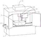
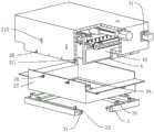
本申请公开的一种真空喷涂设备,如图1和图2所示,包括机架1、包覆于机架1外的罩壳11、连接于罩壳11的真空发生器12、设置于罩壳11内的输送轨道13及设置于罩壳11内的涂覆机构2。罩壳11使用螺栓固定于机架1外,从而使机架1位于罩壳11内的空间内,真空发生器12与罩壳11内部连通,从而对罩壳11内部进行抽真空,使加工环境成为真空。输送轨道13为皮带输送机构,其将工件从上一道工序处输送至罩壳11内,并将加工之后的工件输送出罩壳11并输送至下一工序处,相邻工序的加工环境也为真空。涂覆机构2包括呈下开口设置的防尘罩21、滑移设置于防尘罩21内的若干喷头22、连接于喷头22的液体驱动件23、驱动喷头22水平往复移动的水平驱动件24及带动防尘罩21竖向移动的竖直驱动件25。水平驱动件24在本实施例中选用丝杠滑台,水平驱动件24的架体使用螺栓固定于防尘罩21内腔顶面,水平驱动件24的滑台上使用螺栓固定有安装板,喷头22皆使用螺栓固定于安装板下端面。竖直驱动件25在本实施例中选用气缸,竖直驱动件25的固定端使用螺栓固定于机架1上,竖直驱动件25的活动端使用螺栓与防尘罩21的上端固定,从而带动防尘罩21竖向移动。机架1上还使用螺栓固定有用于盛放钝化材料的药箱14,液体驱动件23在本实施例中选用水泵,液体驱动件23的 进水端与药箱14连通,液体驱动件23的出水端通过管道与防尘罩21内的喷头22连通,管道为柔性管道,且位于防尘罩21内的管道外套设有拖链,拖链使用螺栓固定于防尘罩21内。防尘罩21能够将工件罩设于内,之后在利用喷头22进行钝化药剂喷洒的过程中,钝化药剂集中于防尘罩21内而不会在罩壳11内随意飘散,从而使罩壳11内部的其余机械结构不易与钝化药剂接触而被氧化。A vacuum spraying equipment disclosed in the present application, as shown in Figure 1 and Figure 2, includes a frame 1, a
如图2所示,为了使钝化药剂的喷涂更加均匀,防尘罩21内腔垂直于喷头22移动方向的两个侧壁上皆开设有让位槽211,喷头22能够分别移动至让位槽211内,从而在喷头22对工件进行喷涂时,先使喷头22开始喷射之后喷头22再从工件上方通过,从而在喷头22正常喷涂的情况下再对工件喷涂。并且喷头22在停止之后其位于让位槽211内,使喷头22上滴落的钝化药剂掉落于让位槽211内。As shown in Figure 2, in order to make the spraying of the passivating agent more uniform, there are
如图3所示,由于在喷头22朝向工件上喷射钝化药剂时,钝化药剂会朝向输送轨道13上喷射,从而导致大量的钝化药剂粘附至输送轨道13上,从而影响输送轨道13的使用寿命。因此防尘罩21的下端可拆卸连接有一挡板3,挡板3能够将防尘罩21的下端开口封闭。挡板3下端贯穿有连通孔31,连通孔31的形状及大小与工件的形状及大小相同,工件能够位于连通孔31内。从而在对工件进行喷涂时,挡板3下移从而使工件位于连通孔31内,在喷涂的过程中钝化药剂能够喷涂至挡板3上而不会直接喷涂至输送轨道13上,从而减少输送轨道13受到的钝化药剂的影响。As shown in FIG. 3 , when the nozzle 22 sprays the passivating agent toward the workpiece, the passivating agent will be sprayed toward the conveying
如图3所示,为了使防尘罩21与挡板3的连接更加方便,挡板3上端沿其边沿固定有若干延伸块32,延伸块32靠近防尘罩21的端面贯穿有若干插接孔321。防尘罩21上穿设有若干插接块26,插接块26与防尘罩21螺纹连接,插接块26的一端位于防尘罩21外,插接块26的另一端位于防尘罩21内,且插接块26能够穿设于插接孔321内,从而将挡板3与防尘罩21的位置进行限定。As shown in Figure 3, in order to make the connection between the
如图3所示,为了使钝化药剂不易通过连通孔与工件之间的间隙掉落至输送轨道13上,连通孔的内壁上皆黏连有导向片33,导向片33为橡胶材质,且相邻导向片33相互靠近的位置相互抵接。导向片33远离连通孔侧壁的一端向上倾斜,且皆能够与工件的侧壁抵接。从而利用导向片33将工件与连通孔之间的间隙进行封闭,使钝化药剂不易通过工件与连通孔之间的间隙落入输送轨道13上,从而减少输送轨道13所述受到的钝化药剂的影响。As shown in Figure 3, in order to make the passivation agent not easy to drop onto the conveying
如图3所示,由于在喷涂完成之后,钝化药剂会形成微粒从而充满防尘罩21的空间内,在防尘罩21向上移动之后,钝化药剂形成的微粒弥漫至罩壳11内,因此防尘罩21内还滑移连接有刮板4及驱动刮板4往复移动的分离驱动件41,刮板4通过滑轨滑移设置于防尘罩21内,且刮板4的滑动方向与喷头22的滑动方向保持平行,分离驱动件41在本实施例中选用丝杠及电机的配合结构,分离驱动件41的丝杠穿设于刮板4并与刮板4螺纹连接,从而带动刮板4水平往复移动。在完成一次喷涂之后,刮板4于防尘罩21内水平移动一次,从而将漂浮于防尘罩21内的钝化药剂微粒朝向一侧驱动并附着至刮板4上,在防尘罩21后续向上移动的过程中,减少钝化药剂微粒进入罩壳11内的数量。As shown in Figure 3, since after the spraying is completed, the passivation agent will form particles to fill the space of the
由于钝化药剂的微粒于刮板4上附着数量增加之后,会聚合为小水珠而向下滴落,因此挡板3垂直于其移动方向的两个侧壁上皆使用魔术贴可拆卸连接有吸附片42,吸附片42为棉质,利用吸附片42将钝化药剂形成的微粒进行吸附,使钝化药剂形成的微粒不易聚合产生形成滴落的小水珠,并且吸附片42在吸收钝化药剂之后还能取下进行清洗。Since the particles of the passivating agent are attached to the
如图3所示,挡板3上端使用魔术贴可拆卸连接有用于吸收钝化药剂的第一吸附件34,第一吸附件34为棉布,第一吸附件34将挡板3的上端面完全覆盖。防尘罩21呈竖直的侧壁及让位槽211内皆设置有用于吸收钝化药剂的第二吸附件27,第二吸附件27也为棉布,第二吸附件27靠近防尘罩21的侧壁上缝制有固定块,固定块靠近防尘罩21的端面转动连接有限位块28。防尘罩21上开设有若干与其内腔连通的限位孔212,限位块28能够穿设于限位孔212,且限位块28靠近第二吸附件27的侧壁能够与防尘罩21的外壁抵接。从而利用限位块28将第二吸附件27连接于防尘罩21内壁上,在喷头22进行喷涂钝化材料时利用第一吸附件34及第二吸附件27进行吸附,减少防尘罩21受到的钝化药剂的影响,之后可定期将第一吸附件34及第二吸附件27取下并进行清洗。As shown in Figure 3, the upper end of the
本实施例的实施原理为:工件通过输送轨道13移动至防尘罩21的下端,防尘罩21下降使工件位于连通孔内,喷头22位于让位槽211内开始喷射钝化药剂,接着喷头22从工件上方通过进行喷涂,喷涂完成之后刮板4水平移动一次将钝化药剂形成的微粒刮除,防尘罩21向上移动并脱离工件,工件在输送轨道13的驱动下继续输送。The implementation principle of this embodiment is: the workpiece moves to the lower end of the
本具体实施方式的实施例均为本申请的较佳实施例,并非依此限制本申请的保护范围,故:凡依本申请的结构、形状、原理所做的等效变化,均应涵盖于本申请的保护范围之内。The embodiments of this specific implementation mode are all preferred embodiments of the application, and are not intended to limit the scope of protection of the application. Therefore: all equivalent changes made according to the structure, shape, and principle of the application should be covered by the application. Within the protection scope of this application.
Claims (9)
Translated fromChinesePriority Applications (1)
| Application Number | Priority Date | Filing Date | Title |
|---|---|---|---|
| CN202310105669.6ACN116078596A (en) | 2023-01-29 | 2023-01-29 | Vacuum spraying equipment |
Applications Claiming Priority (1)
| Application Number | Priority Date | Filing Date | Title |
|---|---|---|---|
| CN202310105669.6ACN116078596A (en) | 2023-01-29 | 2023-01-29 | Vacuum spraying equipment |
Publications (1)
| Publication Number | Publication Date |
|---|---|
| CN116078596Atrue CN116078596A (en) | 2023-05-09 |
Family
ID=86202365
Family Applications (1)
| Application Number | Title | Priority Date | Filing Date |
|---|---|---|---|
| CN202310105669.6APendingCN116078596A (en) | 2023-01-29 | 2023-01-29 | Vacuum spraying equipment |
Country Status (1)
| Country | Link |
|---|---|
| CN (1) | CN116078596A (en) |
Citations (7)
| Publication number | Priority date | Publication date | Assignee | Title |
|---|---|---|---|---|
| US5962072A (en)* | 1998-08-03 | 1999-10-05 | Yerman; Arthur J. | Paint mask |
| CN213051215U (en)* | 2020-04-10 | 2021-04-27 | 天津威富达科技发展有限公司 | Big whirlwind recovery system is with spouting room |
| CN213886818U (en)* | 2020-11-09 | 2021-08-06 | 苏州弘盈工程装备科技有限公司 | Ash cleaning chamber of low-emission environment-friendly automatic powder spraying device |
| CN214347335U (en)* | 2020-10-12 | 2021-10-08 | 森泰纳米科技(深圳)有限公司 | Vacuum coating equipment for surface of jewelry |
| CN113828440A (en)* | 2021-08-06 | 2021-12-24 | 安庆中船柴油机有限公司 | Protective spraying method for exposed surface of marine main engine |
| CN215612677U (en)* | 2021-06-21 | 2022-01-25 | 江苏瑞特回转支承有限公司 | Slewing bearing spraying protector |
| CN215843785U (en)* | 2021-07-23 | 2022-02-18 | 南京艾科天喜机电设备有限公司 | Reciprocating scraper blade powder cleaning and recycling equipment used after online plastic spraying of wire mesh |
- 2023
- 2023-01-29CNCN202310105669.6Apatent/CN116078596A/enactivePending
Patent Citations (7)
| Publication number | Priority date | Publication date | Assignee | Title |
|---|---|---|---|---|
| US5962072A (en)* | 1998-08-03 | 1999-10-05 | Yerman; Arthur J. | Paint mask |
| CN213051215U (en)* | 2020-04-10 | 2021-04-27 | 天津威富达科技发展有限公司 | Big whirlwind recovery system is with spouting room |
| CN214347335U (en)* | 2020-10-12 | 2021-10-08 | 森泰纳米科技(深圳)有限公司 | Vacuum coating equipment for surface of jewelry |
| CN213886818U (en)* | 2020-11-09 | 2021-08-06 | 苏州弘盈工程装备科技有限公司 | Ash cleaning chamber of low-emission environment-friendly automatic powder spraying device |
| CN215612677U (en)* | 2021-06-21 | 2022-01-25 | 江苏瑞特回转支承有限公司 | Slewing bearing spraying protector |
| CN215843785U (en)* | 2021-07-23 | 2022-02-18 | 南京艾科天喜机电设备有限公司 | Reciprocating scraper blade powder cleaning and recycling equipment used after online plastic spraying of wire mesh |
| CN113828440A (en)* | 2021-08-06 | 2021-12-24 | 安庆中船柴油机有限公司 | Protective spraying method for exposed surface of marine main engine |
Similar Documents
| Publication | Publication Date | Title |
|---|---|---|
| CN111359419A (en) | A prevent acid mist purifying column that blocks up for industrial waste gas handles | |
| CN111681978B (en) | Wafer cleaning device | |
| CN208800497U (en) | Glass powder slag cleaning device for toughened glass production line processing table top | |
| CN118458422A (en) | A dust-proof conveying equipment for sand and gravel feeding | |
| CN116944624A (en) | Tin coating device for LED lamp production and operation method thereof | |
| CN211891273U (en) | A dust filter type wood processing device | |
| CN116078596A (en) | Vacuum spraying equipment | |
| CN221535874U (en) | Kraft pulp filtering device | |
| CN220144120U (en) | Aluminum ash washs recovery unit | |
| CN111841228A (en) | Flue gas dust removal equipment for atmosphere pollution prevention and control | |
| CN209885488U (en) | Exhaust treatment device for painting metal material | |
| CN106057711A (en) | Water spray removing device applied to wafer gluing cleaner | |
| CN207088734U (en) | A flatbed color printing machine with floating ink cleaning device | |
| CN212329815U (en) | Cutting device is used in processing of hydrogen fuel cell board convenient to maintain | |
| CN211684112U (en) | Shower nozzle wiper mechanism | |
| CN210388743U (en) | Burnishing device is used in ceramic processing | |
| CN209093979U (en) | A kind of cleaning device of intelligent card chip slot | |
| CN116604820A (en) | Spray type spray head cleaning device, cleaning method and sand mold 3D printer | |
| CN118218322B (en) | Omnibearing air-jet dust-removing equipment for mechanical parts | |
| CN218809559U (en) | Explosion-proof equipment for packing convenient to dust disposal | |
| CN111921328A (en) | Industrial energy-saving environment-friendly dust remover | |
| CN222518119U (en) | Dust keeper for construction engineering | |
| CN221164565U (en) | Continuous plasma processing equipment | |
| CN223127526U (en) | A dust removal device for dry powder screening | |
| CN213792426U (en) | Even spraying plastics device of spraying plastics thickness |
Legal Events
| Date | Code | Title | Description |
|---|---|---|---|
| PB01 | Publication | ||
| PB01 | Publication | ||
| SE01 | Entry into force of request for substantive examination | ||
| SE01 | Entry into force of request for substantive examination |