CN116075399A - robot controller - Google Patents
robot controllerDownload PDFInfo
- Publication number
- CN116075399A CN116075399ACN202080102469.XACN202080102469ACN116075399ACN 116075399 ACN116075399 ACN 116075399ACN 202080102469 ACN202080102469 ACN 202080102469ACN 116075399 ACN116075399 ACN 116075399A
- Authority
- CN
- China
- Prior art keywords
- correction
- reliability
- robot
- command value
- calculation unit
- Prior art date
- Legal status (The legal status is an assumption and is not a legal conclusion. Google has not performed a legal analysis and makes no representation as to the accuracy of the status listed.)
- Granted
Links
Images


Classifications
- B—PERFORMING OPERATIONS; TRANSPORTING
- B25—HAND TOOLS; PORTABLE POWER-DRIVEN TOOLS; MANIPULATORS
- B25J—MANIPULATORS; CHAMBERS PROVIDED WITH MANIPULATION DEVICES
- B25J9/00—Programme-controlled manipulators
- B25J9/16—Programme controls
- B25J9/1694—Programme controls characterised by use of sensors other than normal servo-feedback from position, speed or acceleration sensors, perception control, multi-sensor controlled systems, sensor fusion
- B—PERFORMING OPERATIONS; TRANSPORTING
- B25—HAND TOOLS; PORTABLE POWER-DRIVEN TOOLS; MANIPULATORS
- B25J—MANIPULATORS; CHAMBERS PROVIDED WITH MANIPULATION DEVICES
- B25J9/00—Programme-controlled manipulators
- B25J9/16—Programme controls
- B25J9/1656—Programme controls characterised by programming, planning systems for manipulators
- B25J9/1664—Programme controls characterised by programming, planning systems for manipulators characterised by motion, path, trajectory planning
- B—PERFORMING OPERATIONS; TRANSPORTING
- B25—HAND TOOLS; PORTABLE POWER-DRIVEN TOOLS; MANIPULATORS
- B25J—MANIPULATORS; CHAMBERS PROVIDED WITH MANIPULATION DEVICES
- B25J9/00—Programme-controlled manipulators
- B25J9/16—Programme controls
- B25J9/1628—Programme controls characterised by the control loop
- B25J9/163—Programme controls characterised by the control loop learning, adaptive, model based, rule based expert control
- G—PHYSICS
- G05—CONTROLLING; REGULATING
- G05B—CONTROL OR REGULATING SYSTEMS IN GENERAL; FUNCTIONAL ELEMENTS OF SUCH SYSTEMS; MONITORING OR TESTING ARRANGEMENTS FOR SUCH SYSTEMS OR ELEMENTS
- G05B2219/00—Program-control systems
- G05B2219/30—Nc systems
- G05B2219/39—Robotics, robotics to robotics hand
- G05B2219/39001—Robot, manipulator control
- G—PHYSICS
- G05—CONTROLLING; REGULATING
- G05B—CONTROL OR REGULATING SYSTEMS IN GENERAL; FUNCTIONAL ELEMENTS OF SUCH SYSTEMS; MONITORING OR TESTING ARRANGEMENTS FOR SUCH SYSTEMS OR ELEMENTS
- G05B2219/00—Program-control systems
- G05B2219/30—Nc systems
- G05B2219/39—Robotics, robotics to robotics hand
- G05B2219/39298—Trajectory learning
- G—PHYSICS
- G05—CONTROLLING; REGULATING
- G05B—CONTROL OR REGULATING SYSTEMS IN GENERAL; FUNCTIONAL ELEMENTS OF SUCH SYSTEMS; MONITORING OR TESTING ARRANGEMENTS FOR SUCH SYSTEMS OR ELEMENTS
- G05B2219/00—Program-control systems
- G05B2219/30—Nc systems
- G05B2219/39—Robotics, robotics to robotics hand
- G05B2219/39529—Force, torque sensor in wrist, end effector
- G—PHYSICS
- G05—CONTROLLING; REGULATING
- G05B—CONTROL OR REGULATING SYSTEMS IN GENERAL; FUNCTIONAL ELEMENTS OF SUCH SYSTEMS; MONITORING OR TESTING ARRANGEMENTS FOR SUCH SYSTEMS OR ELEMENTS
- G05B2219/00—Program-control systems
- G05B2219/30—Nc systems
- G05B2219/40—Robotics, robotics mapping to robotics vision
- G05B2219/40519—Motion, trajectory planning
- G—PHYSICS
- G05—CONTROLLING; REGULATING
- G05B—CONTROL OR REGULATING SYSTEMS IN GENERAL; FUNCTIONAL ELEMENTS OF SUCH SYSTEMS; MONITORING OR TESTING ARRANGEMENTS FOR SUCH SYSTEMS OR ELEMENTS
- G05B2219/00—Program-control systems
- G05B2219/30—Nc systems
- G05B2219/40—Robotics, robotics mapping to robotics vision
- G05B2219/40584—Camera, non-contact sensor mounted on wrist, indep from gripper
- G—PHYSICS
- G05—CONTROLLING; REGULATING
- G05B—CONTROL OR REGULATING SYSTEMS IN GENERAL; FUNCTIONAL ELEMENTS OF SUCH SYSTEMS; MONITORING OR TESTING ARRANGEMENTS FOR SUCH SYSTEMS OR ELEMENTS
- G05B2219/00—Program-control systems
- G05B2219/30—Nc systems
- G05B2219/40—Robotics, robotics mapping to robotics vision
- G05B2219/40586—6-DOF force sensor
- G—PHYSICS
- G05—CONTROLLING; REGULATING
- G05B—CONTROL OR REGULATING SYSTEMS IN GENERAL; FUNCTIONAL ELEMENTS OF SUCH SYSTEMS; MONITORING OR TESTING ARRANGEMENTS FOR SUCH SYSTEMS OR ELEMENTS
- G05B2219/00—Program-control systems
- G05B2219/30—Nc systems
- G05B2219/40—Robotics, robotics mapping to robotics vision
- G05B2219/40607—Fixed camera to observe workspace, object, workpiece, global
Landscapes
- Engineering & Computer Science (AREA)
- Robotics (AREA)
- Mechanical Engineering (AREA)
- Manipulator (AREA)
- Numerical Control (AREA)
Abstract
Description
Translated fromChinese技术领域technical field
本发明涉及对机器人进行控制的机器人控制装置。The present invention relates to a robot control device for controlling a robot.
背景技术Background technique
在现有的机器人控制装置中,例如基于从编码器输出的位置信息进行高精度的定位控制。近年,为了应对由工件的批次变动等产生的定位误差,应用了作为外界传感器而使用视觉传感器、力觉传感器的机器人控制。提出了如上所述的与工件的定位精度的变动相对应的控制,另一方面,有时由于干扰等的影响,传感器检测信号的信号电平变得不稳定,因此难以进行高精度的控制。In a conventional robot controller, for example, high-precision positioning control is performed based on position information output from an encoder. In recent years, robot control using vision sensors and force sensors as external sensors has been applied in order to cope with positioning errors caused by lot-to-lot variations of workpieces. Control corresponding to fluctuations in workpiece positioning accuracy as described above has been proposed. On the other hand, the signal level of the sensor detection signal may become unstable due to the influence of noise or the like, making it difficult to perform high-precision control.
针对如上所述的课题,在专利文献1中公开了下述技术,即,对由视觉传感器输出的多个数据基于各数据的可靠度进行加权平均,使用得到的数据对机械手的动作指令进行修正,由此实现控制的高精度化。To address the above-mentioned problems,
专利文献1:日本特开平7-266272号公报Patent Document 1: Japanese Patent Application Laid-Open No. 7-266272
发明内容Contents of the invention
对于基于通过传感器得到的表示测量结果的传感器信号而使机器人动作的机器人控制装置而言,期待基于传感器信号而自主地使行动变化。在这里,专利文献1所记载的技术是对从传感器按照时间序列得到的多个数据进行加权平均,但在将多个传感器设置于机器人系统内,对由各传感器输出的数据(传感器信号)进行加权平均而用于控制的情况下,也能够期待实现高精度的控制。但是,在使用同一种类的多个传感器的情况下,如果仅基于由各传感器输出的传感器信号对动作进行控制,则有时会不稳定地动作。例如,由于环境光的变化等的干扰,有时传感器信号不全部正常地输出。在该情况下,即使假设如专利文献1所记载那样使用对多个数据(传感器信号)进行加权平均的结果对机器人的动作指令进行了修正,也无法进行所期待的动作,有时在错误的方向动作,由此与周围发生干涉而损坏系统。为了避免系统损坏,通过将机器人动作预先一律设为低速而能够应对,但其结果,存在由于作业变慢而导致生产效率降低的问题。A robot controller that operates a robot based on a sensor signal indicating a measurement result obtained from a sensor is expected to autonomously change its behavior based on the sensor signal. Here, the technology described in
本发明就是鉴于上述情况而提出的,其目的在于得到在有效使用传感器信号的机器人系统中高精度地进行机器人的控制,且不使生产系统中的生产效率降低而实现机器人动作的机器人控制装置。The present invention was made in view of the above circumstances, and an object of the present invention is to obtain a robot control device that controls a robot with high precision in a robot system that effectively uses sensor signals, and realizes robot operation without reducing productivity in a production system.
为了解决上述的课题,并达到目的,本发明所涉及的机器人控制装置具有可靠度运算部,其输入从在机器人的主体或者机器人的周边环境设置的外界传感器所涉及的表示测量结果的传感器信号得到的特征量,基于特征量的时间上的变化或者空间上的变化对相对于传感器信号的可靠度进行运算。另外,机器人控制装置具有:校正指令值运算部,其基于通过可靠度及特征量而计算出的校正信息,对用于校正机器人的轨道的轨道校正量进行运算;以及指令值生成部,其基于预先确定的机器人的目标轨道和轨道校正量,生成针对机器人的位置指令值。In order to solve the above-mentioned problems and achieve the purpose, the robot control device according to the present invention has a reliability calculation unit whose input is obtained from sensor signals indicating measurement results related to external sensors installed in the main body of the robot or in the surrounding environment of the robot. The feature quantity is calculated based on the temporal change or the spatial change of the feature quantity to calculate the reliability of the sensor signal. In addition, the robot control device has: a correction command value calculation unit that calculates a trajectory correction amount for correcting the trajectory of the robot based on correction information calculated from reliability and feature quantities; and a command value generation unit based on The robot's target trajectory and trajectory correction amount are determined in advance to generate a position command value for the robot.
发明的效果The effect of the invention
本发明所涉及的机器人控制装置具有下述效果,即,能够实现机器人的控制的高精度化和防止生产系统中的生产效率的降低。The robot control device according to the present invention has the effect of realizing higher precision of robot control and preventing reduction of production efficiency in a production system.
附图说明Description of drawings
图1是表示应用实施方式1所涉及的机器人控制装置而实现的机器人系统的结构例的图。FIG. 1 is a diagram showing a configuration example of a robot system realized by applying the robot controller according to
图2是表示实施方式1所涉及的机器人控制装置的结构例的图。FIG. 2 is a diagram showing a configuration example of the robot controller according to
图3是表示实施方式1所涉及的机器人控制装置的可靠度运算部的动作的一个例子的流程图。3 is a flowchart showing an example of the operation of the reliability calculation unit of the robot controller according to the first embodiment.
图4是表示实施方式1所涉及的机器人控制装置的校正指令值运算部的动作的一个例子的流程图。4 is a flowchart showing an example of the operation of the correction command value calculation unit of the robot controller according to the first embodiment.
图5是表示实施方式1所涉及的机器人控制装置的指令值生成部的动作的一个例子的流程图。5 is a flowchart showing an example of operations of a command value generation unit of the robot controller according to
图6是用于说明由实施方式1所涉及的机器人控制装置处理的特征量的定义的第1图。FIG. 6 is a first diagram for explaining the definition of feature quantities handled by the robot controller according to
图7是用于说明由实施方式1所涉及的机器人控制装置处理的特征量的定义的第2图。FIG. 7 is a second diagram for explaining the definition of feature quantities handled by the robot controller according to
图8是用于说明由实施方式1所涉及的可靠度运算部对可靠度进行计算的方法的第1例的图。FIG. 8 is a diagram for explaining a first example of a method of calculating reliability by a reliability calculation unit according to
图9是用于说明由实施方式1所涉及的可靠度运算部对可靠度进行计算的方法的第2例的图。FIG. 9 is a diagram for explaining a second example of a method of calculating reliability by the reliability calculation unit according to
图10是表示应用实施方式1所涉及的机器人控制装置的机器人系统的具体例的图。10 is a diagram showing a specific example of a robot system to which the robot control device according to
图11是表示图10所示的机器人系统中的机器人的目标轨道、实际轨道和校正信息之间的关系的一个例子的图。FIG. 11 is a diagram showing an example of a relationship between a robot's target trajectory, actual trajectory, and correction information in the robot system shown in FIG. 10 .
图12是表示实施方式1所涉及的机器人系统的动作状况的一个例子的图。FIG. 12 is a diagram showing an example of an operation state of the robot system according to
图13是表示图12所示的动作状况中的机器人的目标轨道、实际轨道和校正信息之间的关系的一个例子的图。FIG. 13 is a diagram showing an example of the relationship between the robot's target trajectory, actual trajectory, and correction information in the operation situation shown in FIG. 12 .
图14是表示实现机器人控制装置的硬件的一个例子的图。FIG. 14 is a diagram showing an example of hardware realizing the robot controller.
图15是表示实施方式3所涉及的机器人控制装置的结构例的图。FIG. 15 is a diagram showing a configuration example of a robot controller according to
图16是表示实施方式3所涉及的机器人控制装置的校正倍率运算部的动作的一个例子的流程图。FIG. 16 is a flowchart showing an example of the operation of a correction magnification calculation unit of the robot controller according to
图17是表示实施方式3所涉及的机器人控制装置的指令值生成部的动作的一个例子的流程图。FIG. 17 is a flowchart showing an example of operations of a command value generation unit of the robot controller according to
图18是用于说明实施方式3所涉及的机器人系统的动作的图。FIG. 18 is a diagram for explaining the operation of the robot system according to
图19是表示图18所示的动作状况中的机器人的目标轨道、实际轨道和校正信息之间的关系的一个例子的图。FIG. 19 is a diagram showing an example of the relationship between the robot's target trajectory, actual trajectory, and correction information in the operation situation shown in FIG. 18 .
图20是表示实施方式4所涉及的机器人控制装置的结构例的图。FIG. 20 is a diagram showing a configuration example of a robot controller according to
图21是用于说明实施方式4所涉及的机器人控制装置的实际动作的图。FIG. 21 is a diagram for explaining the actual operation of the robot controller according to the fourth embodiment.
图22是表示图21所示的动作状况中的机器人的目标轨道、实际轨道和校正信息之间的关系的一个例子的图。FIG. 22 is a diagram showing an example of the relationship between the robot's target trajectory, actual trajectory, and correction information in the operation situation shown in FIG. 21 .
图23是表示实施方式5所涉及的机器人控制装置的结构例的图。FIG. 23 is a diagram showing a configuration example of a robot controller according to Embodiment 5. FIG.
图24是表示实施方式5所涉及的机器人控制装置的特征量提取部的动作的一个例子的流程图。24 is a flowchart showing an example of the operation of the feature quantity extraction unit of the robot controller according to the fifth embodiment.
图25是表示实施方式6所涉及的机器人控制装置的指令值生成部的动作的一个例子的流程图。25 is a flowchart showing an example of operations of a command value generation unit of the robot controller according to Embodiment 6. FIG.
图26是用于说明实施方式6所涉及的机器人系统的动作的图。FIG. 26 is a diagram for explaining the operation of the robot system according to the sixth embodiment.
图27是表示图26所示的动作状况中的机器人的目标轨道、实际轨道和校正信息之间的关系的一个例子的图。FIG. 27 is a diagram showing an example of the relationship between the robot's target trajectory, actual trajectory, and correction information in the operation situation shown in FIG. 26 .
图28是用于说明由实施方式6所涉及的机器人控制装置处理的特征量的图。FIG. 28 is a diagram for explaining feature quantities handled by the robot controller according to Embodiment 6. FIG.
图29是用于说明从RGB图像的特征量对第2特征量进行提取的方法的图。FIG. 29 is a diagram for explaining a method of extracting a second feature quantity from feature quantities of an RGB image.
图30是表示实施方式7所涉及的机器人控制装置的结构例的图。FIG. 30 is a diagram showing a configuration example of a robot controller according to Embodiment 7. FIG.
图31是表示实施方式8所涉及的机器人控制装置的结构例的图。FIG. 31 is a diagram showing a configuration example of a robot controller according to Embodiment 8. FIG.
图32是表示实施方式8所涉及的机器人控制装置的学习部的结构例的图。32 is a diagram showing a configuration example of a learning unit of a robot controller according to Embodiment 8. FIG.
图33是表示实施方式9所涉及的机器人控制装置的结构例的图。FIG. 33 is a diagram showing a configuration example of a robot controller according to Embodiment 9. FIG.
图34是表示实施方式9所涉及的机器人控制装置的学习部的结构例的图。FIG. 34 is a diagram showing a configuration example of a learning unit of a robot controller according to Embodiment 9. FIG.
具体实施方式Detailed ways
下面,基于附图,对本发明的实施方式所涉及的机器人控制装置详细地进行说明。Next, the robot controller according to the embodiment of the present invention will be described in detail based on the drawings.
实施方式1.
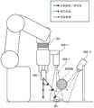
图1是表示应用实施方式1所涉及的机器人控制装置1而实现的机器人系统100的结构例的图。FIG. 1 is a diagram showing a configuration example of a
机器人系统100具有机器人控制装置1、机器人2、外界传感器3和传感器控制器4。此外,机器人系统100的结构与现有的机器人系统相同。即,机器人系统100是将现有的机器人系统的机器人控制装置置换为后面记述的本实施方式所涉及的机器人控制装置1的结构。The
机器人控制装置1与机器人2的主体连接,对针对机器人2的控制指令值进行运算,经由机器人2内的省略了图示的驱动器单元对电动机输送电流值而进行驱动。作为针对机器人2的控制指令值,存在位置指令值、速度指令值、也被称为加速度指令值的扭矩指令值等。驱动器单元基于这些控制指令值,对应该输出至电动机的电动机电流值进行运算。在图1所示的例子中,将针对机器人2的控制指令值设为位置指令值1009。以下,对控制指令值是一般性的工业用机器人控制器的控制指令值的一个即位置指令值的情况下的例子进行说明。The
在这里,在机器人2的主体或者周边环境具有多个外界传感器3,由此能够与在机器人系统的周边发生的周边环境的变化相应地使机器人动作。作为外界传感器3的例子,举出视觉传感器、运动跟踪器、力觉传感器、触觉传感器、接近传感器等。使用这些外界传感器3对作为作业对象物的识别对象进行测量,通过基于测量结果而运算出的特征量生成指令值(在本实施方式中为位置指令值)或者进行修正的控制,是基于外界传感器的控制方式。Here, by having a plurality of
下面,关于通过实施方式1所涉及的机器人控制装置1进行的机器人的控制动作,与所要试图解决的课题一起详细地进行说明。Next, the robot control operation performed by the
首先,对课题进行说明。对于基于信号处理或者信息处理后的识别结果而使机器人动作的机器人控制而言,如上所述,有时利用多个传感器,但在使用同一种类的多个传感器的控制系统中“任1个稳定地动作”成为默认的前提,针对难以预料的状态的控制系统设计是现有课题。另外,在利用不同种类的多个传感器的情况下,主要是分别针对多个传感器而独立地设计反馈控制,无法实现一边与作业状态相应地对多个传感器进行切换,一边进行机器人控制的设计。First, the subject will be explained. For the robot control that moves the robot based on the recognition result after signal processing or information processing, as described above, sometimes a plurality of sensors are used, but in a control system using a plurality of sensors of the same type, "any one of them is stably Action" has become the default premise, and the control system design for unpredictable states is an existing topic. In addition, when multiple sensors of different types are used, feedback control is mainly independently designed for each of the multiple sensors, and robot control cannot be designed while switching the multiple sensors according to the work state.
例如,由于环境光的变化等的干扰,在通过传感器得到的表示测量结果的传感器信号中发生显著的变化,作为其结果,有时传感器信号的特征量没有正常地输出。即,有时表示异常的值的传感器信号从传感器输出。没有正常地输出的情况例如存在下述情况:尽管控制对象的机器人平缓地移动,但对传感器信号进行信号处理而得到的特征量所示的目标地点突然大幅变化的情况,特征量没有输出的情况,错误地识别出的多个目标地点候选中的几个目标地点候选针对目标地点输出的每个定时将错误的目标地点进行输出的情况等。For example, due to disturbances such as changes in ambient light, a sensor signal indicating a measurement result obtained by the sensor changes significantly, and as a result, a characteristic value of the sensor signal may not be output normally. That is, a sensor signal indicating an abnormal value may be output from the sensor. There are cases where the output is not normal. For example, although the robot to be controlled is moving smoothly, the target point indicated by the feature amount obtained by signal processing the sensor signal changes suddenly and greatly, or the feature amount is not output. , a case where several target point candidates among a plurality of target point candidates that were erroneously recognized output a wrong target point for each timing of target point output, and the like.
在该情况下,即使将通过专利文献1所记载的方法对多个传感器信号进行加权平均得到的结果用于机器人控制,有时也不一定进行期待的动作。即,在将传感器信号所示的测量结果或者测量结果的特征量的似然度定义为“可靠度”的情况下,在可靠度降低的情况下,取得以下的2个状态。第1个状态是“在由多个传感器构成的系统的情况下,如果对适当的传感器输出进行选择,则机器人的动作能够继续的情况”,第2个状态是“低于所设想的传感器信号电平或者特征量提取电平,指令值显著地变动而机器人成为失控状态,如果继续动作,则伴有引起作业失败的风险的情况”。至此为止的机器人控制在成为上述的2个状态的任意状态的情况下,是没有能够自动地对控制输出进行调整的机制。In this case, even if the result obtained by weighting and averaging a plurality of sensor signals by the method described in
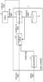
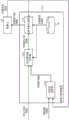
图2是表示实施方式1所涉及的机器人控制装置1的结构例的图。此外,在图2中,关于由机器人控制装置1进行控制的机器人2也一并记载。FIG. 2 is a diagram showing a configuration example of the
机器人控制装置1具有可靠度运算部11、校正指令值运算部12、指令值生成部13及目标轨道保存部14。The
可靠度运算部11将由传感器控制器4对由图1所示的外界传感器3输出的传感器信号进行分析而得到的特征量1005作为输入,基于输入的特征量1005的变化量对传感器信号的可靠度Pc进行计算。此外,传感器信号相当于图1所示的信号1001。另外,特征量1005包含于图1所示的传感器控制器4的输出信息1002。可靠度运算部11将计算出的可靠度Pc作为可靠度1006而输出至校正指令值运算部12。
校正指令值运算部12将可靠度1006及基于上述特征量1005由传感器控制器4计算出的校正信息1003作为输入,基于输入的各信息,对用于校正机器人2的轨道的轨道校正量进行计算。此外,校正信息1003包含于图1所示的传感器控制器4的输出信息1002。校正指令值运算部12将计算出的轨道校正量1004输出至指令值生成部13。The correction command
指令值生成部13将轨道校正量1004、由对事先编程后的目标轨道进行保存的目标轨道保存部14输出的目标轨道1008及由机器人2输出的机器人2的位置信息1010作为输入,基于输入的各信息而生成针对机器人2的位置指令值。目标轨道1008表示通过编程而预先确定的机器人2的轨道。轨道表示将3维上的某时刻t的机器人位置指令值通过一定的时间宽度Δt表现出的数据组。目标轨道的信息的一部分是某时刻的位置指令值。此外,位置信息1010由机器人2所具有的内界传感器生成。指令值生成部13将生成的位置指令值1009输出至机器人2。The command value generation unit 13 takes the
在这里,在本实施方式中,构成为由传感器控制器4对从大于或等于1个外界传感器3输出的各传感器信号进行信号处理而得到与各传感器信号相对应的特征量1005及校正信息1003,但也可以构成为由机器人控制装置1进行用于得到特征量1005及校正信息1003的信号处理。关于该情况下的结构,作为其他实施方式在后面记述。Here, in this embodiment, the
下面,对由机器人控制装置1的可靠度运算部11、校正指令值运算部12及指令值生成部13进行的处理进行说明。Next, the processing performed by the
图3是表示实施方式1所涉及的机器人控制装置1的可靠度运算部11的动作的一个例子的流程图。FIG. 3 is a flowchart showing an example of the operation of the
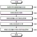
可靠度运算部11如图3所示,取得从传感器控制器4输出的特征量1005(以下,有时记载为特征量Vk)(步骤S11),基于特征量Vk对可靠度Pc进行计算(步骤S12)。而且,可靠度运算部11将计算出的可靠度Pc输出至校正指令值运算部12(步骤S13)。As shown in FIG. 3 , the
在这里,可靠度Pc通过0至1的范围的实数进行定义。关于特征量Vk和可靠度Pc的详细内容在后面记述,但特征量Vk是将某外界传感器SENk(k=1、2、…)在时刻t输出的传感器信号Sk(t)作为输入,通过确定的变换处理对传感器信号Sk(t)进行数值化而表现出的标量即特征量Vk(t),或者是使用特征量矢量Vec_Vk(t)进行计算的。在存在与时刻t相关的特征量Vk的变迁即作为时间序列信息的特征量Vk(t)、基于空间的特征量Vk(X)或者关于时间及空间而变化的特征量Vk(t,X)时,可靠度运算部11基于事先预测的模型、假设,例如使用期待的变化的上限Vth,基于超过上限Vth的特征量Vk的变化的有无、特征量Vk和上限Vth之间的大小关系等,对从期待的上限Vth起的脱离进行指标化而对可靠度Pc进行计算。关于特征量Vk及可靠度Pc的详细内容在后面记述。Here, the reliability Pc is defined by a real number ranging from 0 to 1. The details of the feature quantity Vk and the reliability Pc will be described later, but the feature quantity Vk takes the sensor signal Sk(t) output by a certain external sensor SENk (k=1, 2, ...) at time t as input, and is determined by determining The conversion process of the sensor signal Sk(t) is digitized and the scalar characteristic value Vk(t) is expressed, or the characteristic value vector Vec_Vk(t) is used for calculation. When there is a change in the feature value Vk related to time t, that is, the feature value Vk(t) as time-series information, the feature value Vk(X) based on space, or the feature value Vk(t, X) that changes with respect to time and space In this case, the
此外,在下面的说明中,在不考虑时刻而是对由外界传感器SENk输出的传感器信号进行表现的情况下,将传感器信号表现为Sk,另外,将与由外界传感器SENk输出的传感器信号(Sk)有关的可靠度表现为Pc(k)。In addition, in the following description, when expressing the sensor signal output from the external sensor SENk regardless of the time, the sensor signal is expressed as Sk, and the sensor signal (Sk) output from the external sensor SENk is compared with ) related reliability is expressed as Pc(k).
图4是表示实施方式1所涉及的机器人控制装置1的校正指令值运算部12的动作的一个例子的流程图。FIG. 4 is a flowchart showing an example of the operation of the correction command
校正指令值运算部12如图4所示,取得从传感器控制器4输出的校正信息1003及从可靠度运算部11输出的可靠度1006(Pc(k))(步骤S21),基于校正信息1003及可靠度1006对轨道校正量1004进行计算(步骤S22)。而且,校正指令值运算部12将计算出的轨道校正量1004输出至指令值生成部13(步骤S23)。As shown in FIG. 4 , the correction command
在步骤S22中,校正指令值运算部12将基于由各外界传感器3输出的传感器信号Sk的校正信息1003(校正信息ΔXck)通过可靠度Pc(k)进行加权而求出校正系数,使用该校正系数对轨道校正量1004进行计算。校正指令值运算部12例如作为校正系数Ck(k=1、2、…),基于下述的式(1)及式(2)对轨道校正量ΔXd进行计算。式(2)中的“fnc”表示根据可靠度Pc(k)而求出校正系数Ck的函数。在式(1)中对校正系数Ck与校正信息ΔXck的积进行计算而作为各传感器的轨道校正量的要素,作为传感器整体,取和而输出。In step S22, the correction command
ΔXd=Σ(Ck·ΔXck)…(1)ΔXd=Σ(Ck·ΔXck)...(1)
Ck=fnc(Pc(k))…(2)Ck=fnc(Pc(k))...(2)
此外,也能够是进一步将目标轨道输入至校正指令值运算部12的结构。在该情况下,能够针对轨道校正量ΔXd而限定上限值、校正方向。例如,能够将成为基准的位置指令值Xd作为输入,对轨道校正量ΔXd的上限值ΔXdlim、设为校正对象的方向进行限定。具体地说,在仅对与目标轨道铅垂的朝向实施校正的情况下,有时针对机器人工具坐标系对X、Y、Z或者绕XYZ轴的姿态A、B、C之中的大于或等于1个进行选择而仅对该方向实施校正。In addition, a configuration in which the target trajectory is further input to the correction command
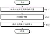
图5是表示实施方式1所涉及的机器人控制装置1的指令值生成部13的动作的一个例子的流程图。FIG. 5 is a flowchart showing an example of the operation of the command value generator 13 of the
指令值生成部13如图5所示,取得从目标轨道保存部14输出的目标轨道1008及从校正指令值运算部12输出的轨道校正量1004(ΔXd)(步骤S31),基于目标轨道1008及轨道校正量1004而生成指令值(步骤S32)。指令值生成部13将生成的指令值输入至机器人2(步骤S33)。在这里,指令值生成部13作为指令值而生成位置指令值1009。As shown in FIG. 5 , the command value generation unit 13 obtains the
在步骤S32中,指令值生成部13例如如果将时刻t的指令值设为Xout(t),将轨道校正量设为ΔXd(t),将目标轨道设为Xd(t),则按照下述的式(3)生成指令值。In step S32, the command value generator 13, for example, assumes that the command value at time t is Xout(t), the trajectory correction amount is ΔXd(t), and the target trajectory is Xd(t), the following procedure is performed: Equation (3) generates command values.
Xout(t)=Xd(t)+ΔXd(t)…(3)Xout(t)=Xd(t)+ΔXd(t)...(3)
指令值生成部13如果没有被输入目标轨道Xd(t)的校正信息(在这里为轨道校正量ΔXd),则将原来的目标轨道Xd(t)作为指令值Xout(t)进行输出而使机器人2动作。If the command value generator 13 is not input with the correction information of the target trajectory Xd(t) (here, the trajectory correction amount ΔXd), it outputs the original target trajectory Xd(t) as the command value Xout(t) to make the
另外,指令值生成部13作为其他方式,作为对至此为止的校正量进行积分的形式而使用ΣΔXd(t),也能够按照下述的式(4)生成指令值。In addition, the command value generating unit 13 can also generate the command value according to the following formula (4) using ΣΔXd(t) as a form of integrating the correction amounts so far as another mode.
Xout(t)=Xd(t)+ΣΔXd(t)…(4)Xout(t)=Xd(t)+ΣΔXd(t)...(4)
指令值Xout的实现方法只要使用目标轨道Xd(t)及轨道校正量ΔXd(t),则并不特别限定于上述的式(3)或者式(4)所示的内容。The method of realizing the command value Xout is not particularly limited to the content shown in the above-mentioned formula (3) or formula (4) as long as the target trajectory Xd(t) and the trajectory correction amount ΔXd(t) are used.
此外,目标轨道1008全部通过事先赋予的形式进行表现,但在机器人控制装置1的动作中针对某起点Xs和终点Xe通过在线对目标轨道进行再计算的情况下,也能够同样地应用。即,目标轨道Xd(t)有时在机器人控制装置1的动作中途进行更新。另外,机器人控制装置1即使输入至指令值生成部13的目标轨道1008是指令值1次量(表示目标轨道的一系列的位置指令值之中的、当前执行中的位置指令值Xd(t)的下一个位置指令值Xd(t+1))等,也能够同样地应用。In addition, all the
下面,为了对本实施方式的结构进行说明,对特征量Vk及可靠度Pc的定义进行说明。Next, in order to explain the configuration of the present embodiment, the definitions of the feature value Vk and the reliability Pc will be described.
基于由外界传感器3输出的传感器信号的控制,首先使用外界传感器3的测量结果(传感器信号)而执行信号处理或者信息处理,取得特征量。特征量根据外界传感器3的种类而存在多样的方式,但在时刻t,对某外界传感器SENk(k=1、2、…)的传感器信号Sk(t)进行变换处理,使用作为特征量而数值化地表现出的标量Vk(t)或者矢量vec_Vk(t)进行计算,在这一点是共通的。矢量vec_Vk(t)在对1个特征量进行处理时,还用于变换为多个独立的物理量而能够表现的情况。例如,在将色调(RGB)和亮度(明暗)等针对1个像素进行定义的情况下,将特征量作为矢量vec_Vk(t)进行处理。In the control based on the sensor signal output from the
此时,如图6所示,在按照时间序列对特征量Vk进行评价的情况下,将t=ta作为数据收集开始点,作为Vk(t=ta+i)(i=1、2、3、…)而不断取得数据。另外,在作为空间对特征量Vk进行评价的情况下,如图7所示,通过Vk(t=ta,[x,y,za])这一形式进行表现。作为变量,包含有时间信息t和地点信息[x,y,z]。在该情况下,地点信息z=za为固定值。另外,关于x、y,表现出在传感器坐标系上排列有传感器要素,在x方向和y方向将传感器配置为格子状的情况。作为特征量Vk,例如能够例示出通过480×640的像素数表现的视觉传感器的各像素中的颜色信息、亮度信息等。在同一时刻t=ta作为空间将地点Xa处的特征量设为Vk(ta,Xa)时,在多个点同时对地点Xa进行评价。并且,有时通过时间序列捕捉到地点Xa在空间上扩展的情况。此外,还可以构成为在地点信息中作为空间中的姿态信息还追加有欧拉角、四元数等。At this time, as shown in FIG. 6, in the case of evaluating the feature quantity Vk in time series, t=ta is used as the data collection start point, and Vk(t=ta+i) (i=1, 2, 3 ,…) and continuously obtain data. In addition, when the feature value Vk is evaluated as a space, it is expressed in the form of Vk(t=ta, [x, y, za]) as shown in FIG. 7 . As variables, time information t and location information [x, y, z] are included. In this case, the location information z=za is a fixed value. In addition, regarding x and y, sensor elements are arranged on the sensor coordinate system, and sensors are arranged in a grid pattern in the x direction and the y direction. As the feature value Vk, for example, color information, brightness information, and the like in each pixel of the visual sensor represented by the number of pixels of 480×640 can be exemplified. When the feature quantity at the point Xa is Vk(ta, Xa) at the same time t=ta as a space, the point Xa is simultaneously evaluated at a plurality of points. In addition, the spatial expansion of the point Xa may be captured in time series. In addition, a configuration may be adopted in which Euler angles, quaternions, and the like are added to the location information as attitude information in space.
作为特征量,除此以外,对外界传感器SENk的电信号进行变换而表现为与物理量等价的特征量Vk(t)。例如,举出将在应变规中流动的电流变化与力的值设为等价的处理等。作为物理量,举出距离、加速度、速度、旋转速度、应变量、轴力、力矩等。这些物理量能够是将所取得的物理量与事先设定的阈值相比较,或通过所取得的物理量和物理量的目标值的差分而实施PID(Proportional Integral Differential)控制这样的使用方法。除此以外,还存在将这些物理量以时刻t0至t1为止的一定采样量(即Vk(t),t0≤t≤t1)取出,使用机器学习等,将其作为波形图案或者波形特征量而作为新的特征量重新提取的方法。作为使用一定范围的信息量的其他特征量,存在将在时刻t0由照相机等取得的一定范围的像素Vk(t0,[jx,jy])的集合(即,作为面而具有扩展性的图像信息Vk(t0,[jx,jy]),0≤jx≤480、0≤jy≤640)作为输入,进行图像处理而得到的识别对象的轮廓线、位置或者事先生成的列表内的对象和识别对象的相似度这样的特征量。As the feature quantity, in addition, the electric signal of the external environment sensor SENk is converted and expressed as a feature quantity Vk(t) equivalent to a physical quantity. For example, a process of making the change of the electric current flowing through the strain gauge equivalent to the value of the force etc. is mentioned. Examples of the physical quantity include distance, acceleration, speed, rotation speed, strain, axial force, moment, and the like. These physical quantities can be used by comparing the obtained physical quantity with a preset threshold value, or implementing PID (Proportional Integral Differential) control based on the difference between the obtained physical quantity and the target value of the physical quantity. In addition, it is also possible to extract these physical quantities with a certain amount of sampling from time t0 to t1 (that is, Vk(t), t0≤t≤t1), and use machine learning to use them as waveform patterns or waveform feature quantities as A method for re-extracting new feature quantities. As another feature quantity using a certain range of information, there is a set of pixels Vk(t0, [jx, jy]) of a certain range acquired by a camera or the like at time t0 (that is, image information having scalability as a plane) Vk(t0, [jx, jy]), 0≤jx≤480, 0≤jy≤640) as input, the contour line and position of the recognition object obtained by image processing, or the object and recognition object in the pre-generated list A feature quantity such as similarity.
特征量Vk在机器人控制装置1中用于下述目的,即,“映入至外界传感器3的对象物是否是(识别为)设为目标的对象物”、“针对外界传感器3的坐标系,对象物所存在的位置在哪(识别、位置推定)”、“对象物的目标状态和当前状态的差异及差分的计算或者提取,差异或者差分的计算或者提取(识别、差分提取)”。The feature value Vk is used in the
特征量Vk有时对与设为目标的特征量Vd的差异进行识别,以机器人的反馈控制为目的而使用。特征量Vk在如加速度传感器或者力觉传感器那样实施校准处理后传感器信号Sk(t)成为物理量的情况下,直接将该物理量用于成为期望的值那样的反馈控制。The feature value Vk may identify a difference from the target feature value Vd and is used for the purpose of feedback control of the robot. When the sensor signal Sk(t) becomes a physical quantity after performing calibration processing like an acceleration sensor or a force sensor, the characteristic quantity Vk is directly used for feedback control to obtain a desired value.
另一方面,有时从通过传感器信号提取出的特征量即第1特征量进一步对第2特征量进行提取,使用第2特征量进行处理。例如,如从传感器信号提取出的图像信息那样,不是使用第1特征量(图像信息)本身的数据,而是使用通过将第1特征量作为输入而进一步对图像信息中的轮廓进行提取的边缘提取处理、提取对象物体的方向的图像信息的主要成分分析处理等数据处理而得到的位置、方向等信息。这相当于从第1特征量对第2特征量进行提取。有时使用第2特征量而进行判定处理、反馈控制等。On the other hand, the second feature amount may be further extracted from the first feature amount which is the feature amount extracted from the sensor signal, and the second feature amount may be used for processing. For example, instead of using the data of the first feature quantity (image information) itself like the image information extracted from the sensor signal, an edge obtained by further extracting the contour in the image information by using the first feature quantity as input is used. Information such as position and direction obtained by data processing such as extraction processing and principal component analysis processing of the image information of the direction of the extraction target object. This corresponds to extracting the second feature quantity from the first feature quantity. Judgment processing, feedback control, and the like may be performed using the second feature amount.
另外,在第2特征量的提取中,可以应用对时间序列数据的一部分进行剪切而作为波形的图案进行学习,或从庞大的事前数据利用有教师机器学习而获得目标状态等各种方法。In addition, in the extraction of the second feature quantity, various methods such as cutting out a part of time-series data to learn as a waveform pattern, or obtaining a target state from huge prior data using teacher machine learning can be applied.
在这里,对根据为了使作业对象物变迁至目的位置而使用的特征量所生成的校正信息进行说明。在本实施方式中,能够将基于机器人2和作业对象物的作用力的机器人指尖的位置的校正量例示为校正信息1003。具体地说,将从6自由度的力传感器输出的测量值S1(sk,k=1)校准为力或者扭矩的单位[N或者Nm]后的输出即力传感器输出的时刻T的值设为特征量V1(T)。此时,为了进行不对机器人末端执行器施加过量的力的控制,将力的目标值设为特征量的目标值Vd,能够基于特征量V1(T)对机器人指尖的位置的校正量ΔXck进行定义。基于以上的定义,如果设置适当的系数K1,则按照下述的式(5),能够根据特征量V1(T)求出校正量ΔXck(T)。Here, the correction information generated based on the feature data used for moving the work object to the target position will be described. In the present embodiment, the amount of correction of the position of the fingertip of the robot based on the acting force of the
ΔXck(T)=K1·(Vd-V1(T))…(5)ΔXck(T)=K1·(Vd-V1(T))...(5)
在这里,该校正量ΔXck(T)成为位置校正量(校正信息1003的一个方式)。除此以外,作为校正量ΔXck(T),速度校正量、加速度校正量、加加速度校正量这样的校正量是基于特征量Vk进行计算的。Here, this correction amount ΔXck(T) becomes a position correction amount (one form of correction information 1003 ). In addition, as the correction amount ΔXck(T), correction amounts such as a velocity correction amount, an acceleration correction amount, and a jerk correction amount are calculated based on the feature value Vk.
此外,在本说明书中,目的位置等“位置”这一表现是指位置为3自由度及姿态为3自由度的合计6自由度的3维空间自由度,针对机器人坐标系Σrob的X、Y、Z的平移方向的位置和通过绕X、Y、Z轴的旋转唯一地确定的机器人前端部的位置信息及姿态信息等价。除此以外,基于外界传感器3,举出识别对象的移动速度、识别对象的移动加速度、与机器人2和外部的接触状态相应地产生的力(作用力)、机器人指尖位置和识别对象的相对距离、相对位置、相对速度、相对加速度。在该情况下,速度信息、加速度信息也同样地,是省略了旋转速度、旋转加速度的表现,实际上对平移方向3自由度和旋转方向3自由度的合计6自由度进行处理。In addition, in this specification, the expression of "position" such as a target position refers to a 3-dimensional spatial degree of freedom with a total of 6 degrees of freedom, including 3 degrees of freedom for a position and 3 degrees of freedom for an attitude. X, Y for the robot coordinate system Σrob The position in the translation direction of , Z is equivalent to the position information and posture information of the front end of the robot uniquely determined by the rotation around the X, Y, and Z axes. In addition, based on the
接下来,对基于特征量而计算可靠度的方法进行说明。Next, a method of calculating reliability based on feature quantities will be described.
关于通过外界传感器SENk(k=1、2、…)的输出即传感器信号Sk而得到的特征量Vk(k=1、2、…),针对其特征量Vk的时间t(t=1、2、…)或者空间X(X=[x,y,z])上不同的特征量Vk(t,X=[x,y,z]),基于其大于或等于2个特征量的相关信息,对针对基于各传感器信号Sk(k=1、2、…)的特征量Vk(k=1、2、3、…)的可靠度Pc进行定义。Regarding the feature quantity Vk (k=1, 2, . . . ) obtained by the output of the external sensor SENk (k=1, 2, . , ...) or different feature quantities Vk(t, X=[x, y, z]) on the space X (X=[x, y, z]), based on the relevant information that is greater than or equal to 2 feature quantities, The degree of reliability Pc with respect to the feature quantity Vk (k=1, 2, 3, . . . ) based on each sensor signal Sk (k=1, 2, . . . ) is defined.
可靠度Pc在存在与时间t及空间X相关联地定义出的特征量Vk时,基于事先预测的模型及假设对超过期待的变化的上限的Vk的变化的有无进行定义。可靠度Pc针对特征量Vk的每个类型而计算方法不同,因此针对每个类型区分而进行说明。The reliability Pc defines the presence or absence of changes in Vk exceeding the upper limit of expected changes based on previously predicted models and assumptions when there is a feature value Vk defined in association with time t and space X. Since the calculation method of reliability Pc is different for each type of feature quantity Vk, it will be described for each type.
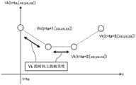
首先,对按照时间序列处理特征量Vk的“Vk(t)”的情况下的可靠度Pc的计算方法进行说明。图8是用于说明由实施方式1所涉及的可靠度运算部11对可靠度Pc进行计算的方法的第1例的图。First, a calculation method of the reliability Pc in the case of processing "Vk(t)" of the feature value Vk in time series will be described. FIG. 8 is a diagram for explaining a first example of a method of calculating the reliability Pc by the
如图8所示,在特征量Vk为时间序列的信息Vk(t,[Xa,ya,za])的情况下,可靠度Pc基于针对某时刻ta的特征量Vk(ta)的过去履历即Vk(ta-i)(i=1、2、3、…)而求出。具体地说,可靠度Pc是基于本次的特征量Vk(ta)的每单位时间的变化量是否超过变化量的上限值ΔVth而求出的。作为其他方法,可靠度Pc使用上限值ΔVth和特征量Vk的一定时间宽度T的履历的平均值(即移动平均),也能够基于特征量Vk的移动平均是否超过上限值ΔVth而求出。另外,上限值ΔVth能够作为针对与之前的值的直接比较,即,在时间上相邻的2个特征量Vk的差的上限进行定义。在这里,在图8所示的例子中,能够将可靠度Pc通过下述的式(6)及式(7)表现。As shown in FIG. 8, when the feature quantity Vk is time-series information Vk(t, [Xa, ya, za]), the reliability Pc is based on the past history of the feature quantity Vk(ta) at a certain time ta, namely Vk(ta-i) (i=1, 2, 3, . . . ) is obtained. Specifically, the reliability Pc is obtained based on whether or not the amount of change per unit time of the current feature quantity Vk(ta) exceeds the upper limit value ΔVth of the amount of change. As another method, the reliability Pc can also be obtained by using the upper limit value ΔVth and the average value (that is, the moving average) of the histories of the feature value Vk for a certain period of time T, and based on whether or not the moving average of the feature value Vk exceeds the upper limit value ΔVth. . In addition, the upper limit value ΔVth can be defined as an upper limit for a direct comparison with the previous value, that is, a difference between two temporally adjacent feature quantities Vk. Here, in the example shown in FIG. 8 , the reliability Pc can be expressed by the following equations (6) and (7).
Pc=[{Vk(t)-Vk(t-1)}/Δt-ΔVth]if{Vk(t)-Vk(t-1)}/Δt>ΔVth…(6)Pc=[{Vk(t)-Vk(t-1)}/Δt-ΔVth]if{Vk(t)-Vk(t-1)}/Δt>ΔVth...(6)
Pc=1if{Vk(t)-Vk(t-1)}/Δt≤ΔVth…(7)Pc=1if{Vk(t)-Vk(t-1)}/Δt≤ΔVth...(7)
接下来,对特征量Vk在空间上被处理的“Vk(ta,[x,y,za])”的情况下的可靠度Pc的计算方法进行说明。Next, a calculation method of the reliability Pc in the case of "Vk(ta, [x, y, za])" in which the feature value Vk is spatially processed will be described.
在特征量Vk为空间信息Vk(ta,[x,y,za])的情况下,可靠度Pc基于某时刻ta的在X、Y方向在面上具有扩展性的空间的某地点[x,y,za](ex.x=1、2、3、…,y=1、2、3、…,z=za(固定))的空间信息Vk(ta,[x,y,za]),对空间上的Vk(t,[x,y,z])的分布如何进行评价。如果与仅关注于时间序列的特征量Vk时相比,则在空间上赋予的情况下的信息量更多,如果对特征量Vk(ta,[x,y,za])的一定量的计算范围进行探索,则能够判别为“空间中的对象正在移动”或者“突然某物在作业对象物前出现”。作为一个例子,使用RGB照相机而得到的图像相当于在空间上处理的特征量Vk。除此以外,从将传感器配置为格子状的传感器阵列得到的传感器信号也可以说是相同的。In the case where the feature quantity Vk is the spatial information Vk(ta, [x, y, za]), the reliability Pc is based on a point [x, y, za] (ex. x = 1, 2, 3, ..., y = 1, 2, 3, ..., z = za (fixed)) spatial information Vk (ta, [x, y, za]), How to evaluate the distribution of Vk(t, [x, y, z]) in space. Compared with when only focusing on the feature quantity Vk of the time series, the amount of information in the case of spatially endowed is more, if a certain amount of calculation of the feature quantity Vk(ta, [x, y, za]) It can be judged as "the object in the space is moving" or "something suddenly appeared in front of the work object" when exploring the range. As an example, an image obtained using an RGB camera corresponds to the spatially processed feature value Vk. In addition, the same can be said for the sensor signals obtained from the sensor array in which the sensors are arranged in a lattice.
如上所述的特征量Vk(t,[x,y,z])的信息量多,因此有时在变换为通过更低维度容易控制的第2特征量Vk2后对可靠度Pc进行计算。使用图9对该情况下的可靠度运算部11的动作进行说明。图9是用于说明由实施方式1所涉及的可靠度运算部11对可靠度Pc进行计算的方法的第2例的图。在图9所示的例子中,可靠度运算部11根据某地点X1和与其相邻的地点X2所相关的信息,生成第2特征量Vk2(t,[X1、X2])。在图9的例子中,作为第2特征量Vk2而得到梯度信息“grad x”及“grad y”。“grad x”示出x轴方向的特征量Vk的梯度,“grad y”示出y轴方向的第1特征量Vk的梯度。梯度信息基于在空间上相邻的上述的特征量Vk的差进行计算。在图9的例子的情况下,在(x,y)=(3,3)处,特征量Vk成为非常小的值。此时,例如在存在“在附近空间中关于Vk没有急剧的变化”这一前提的情况下,能够通过以下所示的方法求出可靠度。Since the above-mentioned feature quantity Vk(t, [x, y, z]) has a large amount of information, the reliability Pc may be calculated after conversion to the second feature quantity Vk2 which is easy to control in a lower dimension. The operation of the
在这里,对定义一定的计算范围而计算可靠度的情况下的例子进行说明。下面,将图9所示的x1至x2及y1至y2的范围表现为[(x1,x2),(y1,y2)]。在该情况下,该范围的可靠度通过下述的式(8)表现。Here, an example in the case of defining a certain calculation range and calculating the reliability will be described. Next, the ranges of x1 to x2 and y1 to y2 shown in FIG. 9 are expressed as [(x1, x2), (y1, y2)]. In this case, the reliability in this range is represented by the following formula (8).
Pc[(x1,x2),(y1,y2)]=1-max(grad x,grad y,[(x1,x2),(y1,y2)])…(8)Pc[(x1, x2), (y1, y2)]=1-max(grad x, grad y, [(x1, x2), (y1, y2)])...(8)
在通过式(8)表现的可靠度的计算中,将图9所示的由粗线包围的框内的[gradx]、[grad y]作为输入,从输入的合计4个梯度中对值最大的梯度进行探索,基于梯度的最大值,梯度越大则可靠度越低。在这里的梯度是指在空间上相邻的2个特征量之间的变化量。在图9所示的例子中,(x,y)=(3,3)处的特征量Vk小于周边,另外,(x,y)=(3,3)以外的地点的特征量Vk相同。另外,(x,y)=(3,3)处的特征量Vk和与其相邻的各地点的特征量Vk之间的梯度全部为0.7。因此,在不包含(x,y)=(3,3)的范围中成为Pc[(x1,x2),(y1,y2)]=1.0,在包含(x,y)=(3,3)的范围中成为Pc[(x1,x2),(y1,y2)]=0.3。例如,如图9所示,范围[(1,2),(1,2)]的可靠度为Pc[(1,2),(1,2)]=1.0,范围[(3,4),(3,4)]的可靠度为Pc[(3,4),(3,4)]=0.3。In the calculation of the reliability expressed by the formula (8), the [gradx] and [grad y] in the box surrounded by the thick line shown in Figure 9 are used as input, and the pair value is the largest among the total 4 input gradients The gradient is explored, based on the maximum value of the gradient, the larger the gradient, the lower the reliability. The gradient here refers to the amount of change between two spatially adjacent feature quantities. In the example shown in FIG. 9 , the feature value Vk at (x, y)=(3,3) is smaller than the surrounding area, and the feature value Vk at points other than (x, y)=(3,3) is the same. In addition, the gradient between the feature value Vk at (x, y)=(3, 3) and the feature value Vk of each adjacent point is all 0.7. Therefore, Pc [(x1, x2), (y1, y2)] = 1.0 in the range not including (x, y) = (3, 3), and in the range including (x, y) = (3, 3) In the range of , Pc[(x1, x2), (y1, y2)]=0.3. For example, as shown in Figure 9, the reliability of the range [(1, 2), (1, 2)] is Pc[(1, 2), (1, 2)] = 1.0, and the range [(3, 4) , (3,4)] is Pc[(3,4), (3,4)]=0.3.
如以上所述,特征量Vk是对将由外界传感器3输出的传感器信号Sk变换为物理量等能够数值运算的信息进行统称而定义的。另外,在存在基于时间序列或者空间的特征量Vk的情况下,基于事先预测的模型或者假设,例如基于期待的变化的上限Vth,根据超过上限Vth的Vk的变化的有无、Vth和Vk之间的大小关系等对可靠度Pc进行计算。As described above, the feature quantity Vk is defined as a general term for information that can be numerically calculated, such as converting the sensor signal Sk output from the
以上述方式定义的可靠度Pc在以下方面与在上述的专利文献1中记载的技术所使用的现有的可靠度相比较优异。现有的可靠度关于来自传感器的输出数据或者作为距离信息的特征量,将其输出的似然度利用为“输出的绝对量”,将其定义为直接可靠度。另一方面,在本实施方式所涉及的机器人系统100中使用的可靠度Pc,在将传感器输出即传感器信号Sk变换为特征量Vk后,基于前后的时间序列、空间上的变化进行定义。由于存在该差异,因此本实施方式所涉及的机器人控制装置1考虑时间上处于过去的履历即特征量Vk(t)及附近空间的特征量Vk(X)的一者或者两者而能够高精度地进行机器人2的控制。The reliability Pc defined as above is superior to the conventional reliability used in the technique described in
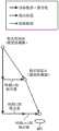
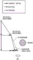
作为一个例子,对图10所示的结构的机器人的控制进行说明。图10是表示应用实施方式1所涉及的机器人控制装置1的机器人系统的具体例的图。图10所示的机器人系统包含进行组装操作的机器人,作为外界传感器而设置有力觉传感器201和视觉传感器202-1及202-2。在如上所述的机器人系统中,机器人控制装置1对机器人进行控制,使末端执行器所抓持的作业对象物即物体300移动至位置301为止。此时,在机器人的主体设置的视觉传感器202-1对视野203-1的范围进行拍摄,将拍摄结果作为传感器信号进行输出。在该机器人系统中,机器人控制装置1基于根据由视觉传感器202-1输出的传感器信号而计算的校正信息A和目标轨道,如图11所示使末端执行器移动。图11是表示图10所示的机器人系统中的机器人的目标轨道、实际轨道和校正信息之间的关系的一个例子的图。As an example, control of a robot configured as shown in FIG. 10 will be described. FIG. 10 is a diagram showing a specific example of a robot system to which the
此时,在图12所示的异物或者人等作为障碍物向环境中侵入的情况下,机器人控制装置1基于特征量Vk的可靠度Pc对障碍物进行检测,进行与状况相对应的行动。例如,机器人控制装置1在对如使用图9说明那样的可靠度进行计算的情况下,在某地点的可靠度低于周边的可靠度的情况下,对机器人进行控制以使得避开可靠度低的地点。例如,机器人控制装置1对机器人2实施对末端执行器的轨道进行修正、对移动速度进行变更、使移动暂时地停止等控制。此时的末端执行器的目标轨道和实际的轨道(实际轨道)之间的关系如图13所示。由此,能够防止发生机器人2及物体300与障碍物的碰撞等而机器人系统100损坏。另外,能够防止机器人系统100的损坏,由此能够避免长时间生产线停止的情况,能够实现生产线的停止时间的减少。At this time, when a foreign object or a person enters the environment as an obstacle as shown in FIG. 12 , the
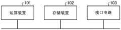
在这里,对实施方式1所涉及的机器人控制装置1的硬件结构进行说明。图14是表示实现机器人控制装置1的硬件的一个例子的图。Here, the hardware configuration of the
机器人控制装置1例如能够通过图14所示的运算装置101、存储装置102及接口电路103实现。运算装置101的例子是CPU(也称为Central Processing Unit、中央处理装置、处理装置、运算装置、微处理器、微型计算机、DSP(Digital Signal Processor))、系统LSI(Large Scale Integration)等。存储装置102的例子是RAM(Random Access Memory)、ROM(Read Only Memory)、硬盘驱动器、SSD(Solid State Drive)、能够装卸的存储器设备或者它们的组合。The
机器人控制装置1的可靠度运算部11、校正指令值运算部12及指令值生成部13是通过由运算装置101执行用于作为这些各部进行动作的程序而实现的。用于作为可靠度运算部11、校正指令值运算部12及指令值生成部13进行动作的程序预先储存于存储装置102。运算装置101通过将上述的程序从存储装置102读出并执行,从而作为可靠度运算部11、校正指令值运算部12及指令值生成部13进行动作。另外,目标轨道保存部14通过存储装置102而实现。The
存储装置102对上述程序进行保存,并且还作为由运算装置101执行各种处理时的暂时存储器使用。接口电路103在机器人控制装置1与机器人2及传感器控制器4之间对数据进行收发时使用。The storage device 102 stores the programs described above, and is also used as a temporary memory when the arithmetic device 101 executes various processes. The interface circuit 103 is used for transmitting and receiving data between the
此外,用于作为机器人控制装置1的各部进行动作的上述的程序预先储存于存储装置102,但并不限定于此。上述的程序可以是在写入至CD(Compact Disc)-ROM、DVD(Digital Versatile Disc)-ROM等记录介质的状态下提供给用户,由用户安装于存储装置102的方式。另外,上述的程序也可以是经由互联网等网络而提供给用户的方式。对实现机器人控制装置1的硬件的例子进行了说明,但后面记述的实施方式2及其以后所说明的各机器人控制装置也能够通过相同的硬件实现。In addition, the above-mentioned programs for operating as the respective units of the
实施方式2.
接下来,对实施方式2所涉及的机器人控制装置进行说明。实施方式2所涉及的机器人控制装置的结构与实施方式1相同(参照图2)。在本实施方式中对与实施方式1不同的部分进行说明。Next, a robot controller according to
在实施方式2所涉及的机器人控制装置1中,在实施方式1中说明的可靠度运算部11与实施方式1的不同点在于,使用从大于或等于2个外界传感器3的传感器信号得到的大于或等于2个特征量1005(Vk、Vk+1、…)对可靠度进行计算。In the
实施方式2所涉及的可靠度运算部11,在针对由某外界传感器SENk输出的传感器信号Sk的特征量Vk计算出的可靠度Pc(k)由于特征量Vk急剧地变化而成为小于1的值的情况下,对与其他外界传感器SENk+1相关的特征量Vk+1进行确认,在特征量Vk+1也同时视作降低倾向的情况下,作为实际上引起变化进行处理。即,特征量Vk本身的可靠度Pc(k)不低,可靠度运算部11基于特征量Vk+1或者可靠度Pc(k+1)将可靠度Pc(k)校正为大的值。该处理通过下述的式(9)及(10)表示。在式(9)中,Kw为加权系数,Kw越小,则来自其他外界传感器SENk+1的传感器信号的特征量的值越接近时将可靠度Pc设定为越接近1。In the
Pc(k)=Pc(k)+(1-Pc(k))/{1+Kw·ABS(Pc(k)-Pc(k+1))}Pc(k)=Pc(k)+(1-Pc(k))/{1+Kw ABS(Pc(k)-Pc(k+1))}
When{Pc(k)-Pc(k+1)}≤ΔPc_th…(9)When{Pc(k)-Pc(k+1)}≤ΔPc_th...(9)
Pc(k)=Pc(k)Pc(k)=Pc(k)
When{Pc(k)-Pc(k+1)}>ΔPc_th…(10)When{Pc(k)-Pc(k+1)}>ΔPc_th...(10)
除此以外,考虑构成为在使用大于或等于2个种类不同的外界传感器3的情况下,关于通过校正指令值运算部12进行的与传感器信号Sk相对应的轨道校正量的运算,校正指令值运算部12在与由其他种类的外界传感器SENk输出的传感器信号Sk+1相对应的可靠度Pc(k+1)高,将有效的校正量ΔXck+1输出的情况下,减小与传感器信号Sk相关的校正量ΔXck的加权系数wk。但是,wk通过|wk|<1进行定义,如下述的式(11)~(13)那样能够对轨道校正量ΔXd进行定义。In addition, in the case of using two or more
ΔXd=Σ(Ck·wk·ΔXck)…(11)ΔXd=Σ(Ck·wk·ΔXck)...(11)
Ck=fnc(Pc(k))…(12)Ck=fnc(Pc(k))...(12)
wk=fnc(Pc(k+1),Xck+1)…(13)wk=fnc(Pc(k+1), Xck+1)...(13)
此时的校正指令值运算部12的处理,具体地说考虑以下的事例。例如,在图12所示的机器人系统中,装载有视觉传感器SENk(视觉传感器202-1)和取得与机器人的末端执行器、工件等物体300和周边环境的接触相关的力信息的力觉传感器SENk+1(力觉传感器201),机器人2进行实施组装作业的任务。在该条件下,考虑由校正指令值运算部12进行与视觉传感器SENk相关的轨道校正量的计算的情况。校正指令值运算部12作为与基于由视觉传感器SENk输出的传感器信号Sk的可靠度的校正系数Ck独立的指标,能够基于由力觉传感器SENk+1输出的传感器信号Sk+1对加权系数wk进行自动调整。例如,在由力觉传感器SENk+1输出的传感器信号Sk+1的值大于规定的阈值的情况下设为接触状态,将加权系数wk设为与1相比非常小的值。另一方面,在由力觉传感器SENk+1输出的传感器信号Sk+1的值小于或等于规定的阈值而非接触状态的情况下(即Xck+1大致为0的情况下)将加权系数wk大致设为1。该调整在末端执行器和障碍物等处于接触状态,如果按照基于由视觉传感器输出的传感器信号进行运算的校正量(位置校正量)进行轨道校正,则接触状态会恶化的情况下有效。The processing of the correction command
根据以上的结构,在通过具有大于或等于2个的多个外界传感器3的机器人系统100进行校正指令值生成的机器人控制装置1中,特别地,能够使用与某外界传感器3以外的其他外界传感器3相对应的可靠度1006(可靠度Pc(k+1))或者校正信息1003进行可靠度Pc(k)的校正。由此,通过与传感器的故障切离的形式对异物混入、人侵入这样的不规则的状态进行检测,能够动作继续及进行尽快的异常状态检测。其结果,能够得到生产系统的停止时间的缩短、生产效率的提高这样的特别的效果。According to the above structure, in the
实施方式3.
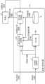
图15是表示实施方式3所涉及的机器人控制装置1a的结构例的图。机器人控制装置1a构成为在实施方式1所涉及的机器人控制装置1中还追加校正倍率运算部15,将指令值生成部13置换为指令值生成部13a。在图15中,对与实施方式1所涉及的机器人控制装置1相同的结构要素标注同一标号。在本实施方式中对与实施方式1不同的部分进行说明。FIG. 15 is a diagram showing a configuration example of a
在校正倍率运算部15中,基于由可靠度运算部11计算的可靠度1006,进行在目标轨道行进的速度指标即倍率值的校正,生成校正倍率。校正倍率运算部15以可靠度1006越低则校正倍率越低的方式对校正倍率1007进行运算,输出至指令值生成部13a。指令值生成部13a基于轨道校正量1004、目标轨道1008、通过机器人2的内界传感器的测量结果而得到的位置信息1010和校正倍率1007,生成位置指令值1009。In the correction
图16是表示实施方式3所涉及的机器人控制装置1a的校正倍率运算部15的动作的一个例子的流程图。FIG. 16 is a flowchart showing an example of the operation of the correction
校正倍率运算部15如图16所示,取得从可靠度运算部11输出的可靠度1006(步骤S41),基于可靠度1006,作为指令值的校正所使用的校正系数对校正倍率进行计算(步骤S42)。而且,校正倍率运算部15将计算出的校正倍率1007输出至指令值生成部13a(步骤S43)。As shown in FIG. 16, the correction
在这里,校正倍率例如能够通过0~100%进行定义。在该情况下,如果校正倍率为0%,则停止机器人2行进,如果校正倍率为100%,则机器人2在目标轨道按照设计的速度进行动作。此外,在此后的说明中,有时将校正倍率记载为OvrdC。另外,在此后的说明中,校正倍率OvrdC基本上将1.0作为初始值,取得0~1的范围的实数。在校正倍率运算部15中,对针对每个传感器的多个校正倍率OvrdC(k)进行运算。Here, the correction magnification can be defined by, for example, 0 to 100%. In this case, if the correction magnification is 0%, the
图17是表示实施方式3所涉及的机器人控制装置1a的指令值生成部13a的动作的一个例子的流程图。FIG. 17 is a flowchart showing an example of the operation of the
指令值生成部13a如图17所示,取得从目标轨道保存部14输出的目标轨道1008(Xd)、从校正指令值运算部12输出的轨道校正量1004(ΔXd)及从校正倍率运算部15输出的校正倍率1007(OvrdC)(步骤S51),基于目标轨道1008、轨道校正量1004及校正倍率1007而生成指令值(步骤S52)。指令值生成部13a将生成的指令值输出至机器人2(步骤S53)。As shown in FIG. 17, the
在步骤S52中,指令值生成部13a基于校正倍率OvrdC(0~1)对输入的目标轨道Xd或者轨道校正量ΔXd的执行量进行校正,从而进行与速度变化等价的处理,生成指令值。例如,如果伴随可靠度Pc的降低而校正倍率OvrdC降低,则在使机器人指尖的移动速度减小的方向进行作用。In step S52, the command
例如,考虑图18所示的事例,即,在安装于机器人2的视觉传感器202-2的视野203-1存在障碍物的情况。在图18所示的情形中,指令值生成部13a与校正信息ΔXd一起取得的可靠度Pc成为低的值,与此相伴,校正倍率OvrdC降低。其结果,机器人2如图19所示,不按照没有障碍物的情况下的轨道,即,单点划线的朝下箭头211所示的目标轨道行进,而是按照粗实线的朝下箭头212以减速的形式继续动作。For example, consider the case shown in FIG. 18 in which an obstacle exists in the field of view 203 - 1 of the visual sensor 202 - 2 attached to the
在事先赋予的目标轨道Xd通过位置的点列赋予的情况下,指令值生成部13a将目标轨道Xd换算为各地点处的针对每个控制周期的下一个目标位置的移动速度vd,根据移动速度vd减少的情况下的1个控制周期量的移动量,对应用校正倍率OvrdC后的目标位置Xdc进行运算。In the case where the target trajectory Xd assigned in advance is given by the point sequence of the position, the
校正倍率运算部15基于可靠度1006进行计算的校正倍率OvrdC,例如如下述的式(14)所示,能够定义为与多个传感器信号Sk相关的可靠度Pc(k)中的最小值。The correction magnification OvrdC calculated by the correction
OvrdC=min(Pc(k))…(14)OvrdC=min(Pc(k))...(14)
除此以外,存在下述方法,即,校正倍率运算部15将与多个传感器信号Sk分别相对应的多个校正倍率OvrdC(k)进行输出,指令值生成部13a对与多个传感器信号Sk分别相对应的多个校正信息ΔXck之中的、向轨道校正量ΔXd的比例最大者所对应的校正倍率OvrdC(k)进行选择而进行指令值的生成。In addition, there is a method in which the correction
将具有以上结构的校正倍率运算部15追加至实施方式1所涉及的机器人控制装置1而设为机器人控制装置1a,从而在机器人系统100的动作中,通过与外界传感器3的故障切离的形式对异物的混入、人的侵入这样的不规则的状态进行检测,能够继续低速的动作或者不碰撞对异常状态进行检测。其结果,能够得到生产系统的停止时间的缩短、生产效率的提高这样的特别的效果。By adding the correction
实施方式4.
图20是表示实施方式4所涉及的机器人控制装置1b的结构例的图。机器人控制装置1b是将实施方式3所涉及的机器人控制装置1a的校正倍率运算部15置换为校正倍率运算部15b的结构。在图20中,对与实施方式3所涉及的机器人控制装置1a相同的结构要素标注同一标号。在本实施方式中对与实施方式3不同的部分进行说明。FIG. 20 is a diagram showing a configuration example of a
实施方式3的校正倍率运算部15的处理和实施方式4的校正倍率运算部15b的处理的差异点在于,在对校正倍率OvrdC(k)进行运算时,在设为对象的外界传感器3即第1外界传感器的传感器信号Sk的可靠度1006(Pc(k))的基础上,将其他外界传感器3即第2外界传感器的传感器信号Sk+1的特征量1005(Vk+1)作为向校正倍率运算部15b的输入,校正倍率运算部15b如下述的式(15)及式(16)所示对校正倍率OvrdC(k)进行运算。具体地说,校正倍率运算部15b在特征量Vk+1小于或等于阈值ΔVth的情况下,与可靠度Pc(k)相应地对校正倍率进行运算,在超过阈值ΔVth的情况下不对校正倍率进行运算而将0输出。在本实施方式中,阈值ΔVth的大小关系及函数的定义并不限定于下述情况,但特征点在于,基于某特征量Vk+1是否超过阈值ΔVth对算式进行切换。The difference between the processing of the correction
OvrdC(k)=fnc(Pc(k))Vk+1≤ΔVth…(15)OvrdC(k)=fnc(Pc(k))Vk+1≤ΔVth...(15)
OvrdC(k)=0Vk+1>ΔVth…(16)OvrdC(k)=0Vk+1>ΔVth...(16)
例如,在图21所示的机器人系统中,考虑对基于通过视觉传感器202-1、202-2、距离传感器(未图示)等进行的非接触的测量的信息和基于通过力觉传感器201、触觉传感器(未图示)等进行的接触的信息进行组合而有效使用。视觉传感器202-1(以下设为视觉传感器SENk)、机器人2的末端执行器及取得与工件和周边环境的接触相关的力信息的力觉传感器201(以下设为力觉传感器SENk+1)装载于机器人,机器人2进行实施组装作业的任务。考虑此时进行与视觉传感器SENk相关的轨道校正量的计算的情况。在该情况下,如图22所示,作为与基于视觉传感器SENk的传感器信号Sk的可靠度Pc(k)的校正系数Ck独立的指标,基于能够测量力信息的力觉传感器SENk+1的传感器信号Sk+1的特征量Vk+1(图示的特征量B),能够对与视觉传感器SENk相关的校正倍率OvrdC(k)(图示的校正信息A)进行自动调整。For example, in the robot system shown in FIG. 21 , consider information based on non-contact measurement by visual sensors 202 - 1 , 202 - 2 , distance sensors (not shown), etc., and information based on
根据本实施方式,在具有多个外界传感器3的机器人系统100中,在难以进行与作业状况相对应的动作速度调整的情况下,能够容易构成通过基于非接触的测量的传感器信号Sk的特征量Vk及基于发生接触的测量的传感器信号Sk+1的特征量Vk+1的组合而自动地进行速度调整的系统。作为结果,能够以短时间启动不易发生系统停止的机器人系统,因此能够实现产品制造所涉及的工厂的运转率及生产效率的提高。According to the present embodiment, in the
实施方式5.Implementation mode 5.
图23是表示实施方式5所涉及的机器人控制装置1c的结构例的图。机器人控制装置1c是在实施方式3所涉及的机器人控制装置1a中追加有特征量提取部16的结构。在图23中,对与实施方式3所涉及的机器人控制装置1a相同的结构要素标注同一标号。在本实施方式中对与实施方式3不同的部分进行说明。FIG. 23 is a diagram showing a configuration example of a
图24是表示实施方式5所涉及的机器人控制装置1c的特征量提取部16的动作的一个例子的流程图。FIG. 24 is a flowchart showing an example of the operation of the feature extraction unit 16 of the
特征量提取部16如图24所示,从传感器控制器4取得表示通过外界传感器3得到的测量结果的信息即外界传感器3的输出信息1002(步骤S61),基于输出信息1002对特征量进行提取(步骤S62)。特征量提取部16将提取出的特征量1005输出至可靠度运算部11(步骤S63)。As shown in FIG. 24 , the feature extraction unit 16 acquires
另外,特征量提取部16根据通过步骤S62提取出的特征量对校正信息进行计算(步骤S64),将计算出的校正信息1003输出至校正指令值运算部12(步骤S65)。In addition, the feature quantity extraction unit 16 calculates correction information based on the feature quantity extracted in step S62 (step S64 ), and outputs the
由特征量提取部16进行计算的校正信息1003并不限定于与位置相关,也能够设为与速度、加速度、加加速度相关。在本实施方式中,校正信息1003基于位置信息被进行计算。由特征量提取部16进行计算的校正信息1003,例如能够设为实施方式1中说明的式(5)所示的校正量ΔXck(T)。The
在如上所述的结构的情况下,特征量提取部16针对L个外界传感器3的输出信息1002,能够输出M个校正信息及N个特征量(L、M、N为大于或等于2的自然数)。In the case of the above-mentioned structure, the feature quantity extraction unit 16 can output M pieces of correction information and N pieces of feature quantity (L, M, and N are natural numbers greater than or equal to 2) for the
特征量提取部16例如对由距离传感器SENk及RGB照相机SENk+1这2个传感器输出的传感器信号Sk及Sk+1进行组合,在进行对作业对象物的品种进行识别的处理后,基于识别出的品种的模型信息,能够从RGB图像的特征量Vk将作业对象物的中心位置坐标作为第2特征量Vk2进行输出。The feature extraction unit 16, for example, combines the sensor signals Sk and Sk+1 output from two sensors, the distance sensor SENk and the RGB
通常,如上所述的处理大多作为传感器控制器4侧的应用而被组合,但通过在机器人控制装置1c侧设置特征量提取部16,从而成为对于作为冗余的多个传感器输入希望将特征量Vk或者第2特征量Vk2的1个输出的情况有效的结构。Usually, the above processing is often combined as an application on the
由此,能够提高输入至可靠度运算部11的特征量1005本身的信息的似然度。作为结果,本实施方式能够减少系统的停止时间,能够实现生产系统的运转率的提高及生产效率的提高。Thereby, the likelihood of the information of the
此外,在本实施方式中,对在实施方式3所涉及的机器人控制装置1a中追加有特征量提取部16的结构进行了说明,但也能够构成为在实施方式1所涉及的机器人控制装置1中追加有特征量提取部16。In addition, in the present embodiment, the structure in which the feature quantity extraction unit 16 is added to the
实施方式6.Implementation mode 6.
接下来,对实施方式6所涉及的机器人控制装置进行说明。实施方式6所涉及的机器人控制装置的结构与实施方式1相同(参照图2)。在本实施方式中对与实施方式1不同的部分进行说明。Next, a robot controller according to Embodiment 6 will be described. The configuration of the robot controller according to Embodiment 6 is the same as that of Embodiment 1 (see FIG. 2 ). In this embodiment, differences from
在实施方式6所涉及的机器人控制装置1中,由指令值生成部13生成指令值的动作与实施方式1不同。In the
图25是表示实施方式6所涉及的机器人控制装置1的指令值生成部13的动作的一个例子的流程图。FIG. 25 is a flowchart showing an example of the operation of the command value generator 13 of the
本实施方式所涉及的指令值生成部13如图25所示,取得从目标轨道保存部14输出的目标轨道1008(Xd)、从校正指令值运算部12输出的轨道校正量1004(ΔXd)、由外界传感器3测量的机器人2的参照点和对象物之间的距离信息及从可靠度运算部11输出的可靠度1006(步骤S71)。机器人2的参照点设置于机器人2的主体或者周边环境,在外界传感器3为视觉传感器的情况下存在于视觉传感器的拍摄范围内。As shown in FIG. 25 , the command value generation unit 13 according to this embodiment acquires the target trajectory 1008 (Xd) output from the target
指令值生成部13接下来,基于轨道校正量1004、机器人2的参照点和对象物之间的距离信息及可靠度1006,对针对目标轨道1008的每个控制周期的移动量进行校正(步骤S72)。Next, the command value generation unit 13 corrects the movement amount for each control cycle of the
指令值生成部13接下来,基于针对目标轨道1008的校正后的每个控制周期的移动量而生成指令值(步骤S73),将生成的指令值输出至机器人2(步骤S74)。Next, the command value generator 13 generates a command value based on the corrected movement amount per control cycle with respect to the target trajectory 1008 (step S73 ), and outputs the generated command value to the robot 2 (step S74 ).
在本实施方式所涉及的机器人控制装置1中,由指令值生成部13进行实施方式3中说明的对校正倍率1007进行运算的处理,即,对在目标轨道行进的速度指标即倍率值进行校正的处理。此时,指令值生成部13取代上述的校正倍率运算部15所使用的传感器信号Sk的可靠度Pc,而是使用上述的距离信息。In the
说明使用上述的距离信息对倍率值进行校正的情况下的具体例。例如,在机器人系统100将工业产品的组装作业作为任务的情况下,将工业产品的部件取出的机器人指尖的位置成为上述的参照点,组装目的地的机器人指尖的位置是机器人2的目标地点,成为上述的对象。作为取得距离信息的方法,存在直接地使用激光位移计等进行测量而取得的方法,有效使用视觉传感器202-1,根据如图26及图27所示作为第2特征量得到的图像上的对象物的尺寸对接近状态进行推定而对距离信息进行计算的方法等。A specific example of correcting the magnification value using the distance information described above will be described. For example, when the
对使用视觉传感器作为第2特征量从对象物的尺寸对与机器人的参照点的距离进行换算的方法进行补充说明。首先,在图28例示出图像处理所涉及的特征量的提取事例。图28在存在RGB图像的情况下,模拟出从RGB图像对圆的中心和半径进行提取而作为特征量Vk的处理。A supplementary description will be given of a method of converting the distance from the robot's reference point from the size of the object using the visual sensor as the second feature quantity. First, an example of feature quantity extraction related to image processing is shown in FIG. 28 . FIG. 28 simulates the process of extracting the center and radius of a circle from the RGB image as the feature value Vk when the RGB image exists.
图29是用于说明从RGB图像的特征量对第2特征量Vk2进行提取的方法的图。FIG. 29 is a diagram for explaining a method of extracting the second feature value Vk2 from the feature values of an RGB image.
图29示出了从特征量Vk对圆的外形、圆的中心及圆的半径Rk进行提取而作为第2特征量Vk2的情况。在考虑第2特征量Vk2的时间序列变化时,图29的右上的图示出了局部的噪声急速出现的情况,可知可靠度Pc(k)和圆的中心及半径的信息即第2特征量Vk2发生变化的情况。另外,图29的右下的图示出图像的右下部分的颜色变化的情况,具体地说,拍摄到异物的情况。在该情况下,颜色的时间上的变化急剧,因此可靠度Pc暂时地降低。FIG. 29 shows a case where the outer shape of the circle, the center of the circle, and the radius Rk of the circle are extracted from the feature quantity Vk as the second feature quantity Vk2. When considering the time-series change of the second feature quantity Vk2, the upper right diagram of Fig. 29 shows the situation where local noise appears rapidly, and it can be seen that the reliability Pc(k) and the information of the center and radius of the circle are the second feature quantity The case where Vk2 changes. In addition, the lower right diagram in FIG. 29 shows a case where the color of the lower right portion of the image changes, specifically, a case where a foreign object is captured. In this case, the temporal change of the color is sharp, so the reliability Pc temporarily decreases.
接下来,对本实施方式所涉及的由指令值生成部13生成指令值的方法进行说明。指令值生成部13首先在基于第2特征量Vk2的对象物的近似圆的半径Rk变大的情况下,如果将设为目标的地点处的外形的近似圆的半径设为Rdk、将距离设为Ld,则接近距离Lc能够按照下述的式(17)进行定义。此外,Kr设为适当的常数。Next, a method for generating a command value by the command value generating unit 13 according to the present embodiment will be described. The command value generation unit 13 first, when the radius Rk of the approximate circle of the object based on the second feature value Vk2 becomes larger, assumes that the radius of the approximate circle of the outer shape at the target point is Rdk and the distance is Rdk. is Ld, the approach distance Lc can be defined according to the following formula (17). In addition, Kr is set to an appropriate constant.
Lc=Ld·{1-Kr·(Rk-Rdk)}…(17)Lc=Ld·{1-Kr·(Rk-Rdk)}...(17)
此时,指令值生成部13应用可靠度Pc越小,或者,如果接近距离Lc低于接近阈值Lth,则与实施方式3所说明的减小校正倍率的情况相同的处理,对执行量进行校正而减小执行量。对该执行量进行校正而减小的处理是将目标轨道换算为速度波形,不使轨道变化,而是使沿轨道的线速度以一定比例量降低的处理。指令值生成部13基于该情况下的轨道将速度图案换算为位置指令值。At this time, the smaller the application reliability Pc is, or the approach distance Lc is lower than the approach threshold Lth, the command value generator 13 corrects the execution amount by the same process as the case of reducing the correction magnification described in the third embodiment. And reduce the amount of execution. The process of correcting and reducing the execution amount is a process of converting the target trajectory into a velocity waveform and reducing the linear velocity along the trajectory by a constant ratio without changing the trajectory. The command value generator 13 converts the velocity pattern into a position command value based on the trajectory in this case.
根据以上的结构,基于与对象物的接近距离Lc及对其接近距离Lc进行测量的外界传感器3输出的传感器信号的特征量Vk的可靠度Pc(k)而规定动作速度,因此自动地对机器人动作速度进行调整。作为结果,能够得到减少机器人系统100的启动时的调整工时这样的特别的效果。According to the above configuration, the operating speed is specified based on the proximity distance Lc to the object and the reliability Pc(k) of the sensor signal characteristic value Vk output by the
实施方式7.Implementation mode 7.
图30是表示实施方式7所涉及的机器人控制装置1d的结构例的图。机器人控制装置1d是将实施方式1所涉及的机器人控制装置1的可靠度运算部11置换为可靠度运算部11d的结构。在图30中,对与实施方式1所涉及的机器人控制装置1相同的结构要素标注同一标号。在本实施方式中对与实施方式1不同的部分进行说明。FIG. 30 is a diagram showing a configuration example of a
向可靠度运算部11d输入特征量1005及机器人2的位置信息1010。可靠度Pc是仅基于特征量Vk的指标,但可靠度运算部11d基于机器人2的位置信息1010(Xa(t))的履历对特征量Vk(t)的变化进行预测,将特征量的预测值Vkp和实际的特征量Vk进行比较,从而对时刻t的特征量Vk(t)的可靠度低的可能性进行预测。The
对具体例进行说明。在利用了使用外界传感器3的传感器反馈控制的机器人系统100中,机器人控制装置1d基于轨道校正量1004的更新值对机器人2输出位置指令值1009。此时,可靠度运算部11d如果取得使机器人指尖位置移动后的位置信息的履历而作为Xa(t),则通过Xa(t)能够对通过在下一个瞬间由外界传感器3输出的传感器信号Sk得到的特征量Vk的变化,即通过环境变化得到的特征量Vk所期待的变化及发生变化的方向进行一定程度预测。A specific example will be described. In the
对特征量Vk所期待的变化的事例进行说明。基于传感器反馈控制进行计算的校正信息ΔXck,针对某传感器信号Sk,以特征量Vk和目标特征量Vdk的差变小的方式输出。在这里,将特征量差的履历ΔVk按照下述的式(18)进行定义。An example of an expected change in the feature value Vk will be described. The correction information ΔXck calculated based on the sensor feedback control is output such that the difference between the characteristic value Vk and the target characteristic value Vdk becomes smaller for a certain sensor signal Sk. Here, the history ΔVk of the feature quantity difference is defined according to the following equation (18).
ΔVk(t)=Vk(t)-Vdk(t)…(18)ΔVk(t)=Vk(t)-Vdk(t)...(18)
此时,与在特征量差的履历ΔVk(t)变大的情况下期待的倾向不同,因此可靠度运算部11d进行减小可靠度Pc的校正,将校正后的可靠度Pc输出至校正指令值运算部12。At this time, it is different from the expected tendency when the history ΔVk(t) of the feature value difference becomes large, so the
另外,对发生变化的方向的事例进行说明。在Xa(t)向特定的方向行进的情况下,如果将与该轴正交的特征量成分定义为Vk_crs,将向与移动方向正交的方向的特征量差的履历设为ΔVk_crs,则ΔVk_crs原本应该几乎不变化。因此,在向与移动方向正交的方向的特征量差的履历ΔVk_crs的变化大于一定的阈值ΔVk_th的情况下,发生设想外的现象的可能性高,因此能够减小可靠度Pc。即,可靠度运算部11d在特征量差的履历ΔVk_crs的变化大于阈值ΔVk_th的情况下,将可靠度Pc校正为小的值而输出至校正指令值运算部12。In addition, an example of a changed direction will be described. When Xa(t) moves in a specific direction, if the feature quantity component perpendicular to the axis is defined as Vk_crs, and the history of feature quantity difference in the direction perpendicular to the moving direction is ΔVk_crs, then ΔVk_crs It should have been little changed. Therefore, when the change in the history ΔVk_crs of the feature value difference in the direction perpendicular to the moving direction exceeds a certain threshold ΔVk_th, there is a high possibility that an unexpected phenomenon will occur, so the reliability Pc can be reduced. That is, the
如以上所述,在机器人2基于外界传感器3的传感器反馈进行动作的情况下,存在期待的特征量Vk的变化及变化的方向。可靠度运算部11d基于机器人2的指尖位置的履历Xa而求出特征量Vk的期待的变化的量及方向,基于与实际的特征量Vk的比较结果对可靠度Pc进行校正,由此使可靠度Pc的似然度提高。其结果,得到使系统的运转率及生产效率提高这样的效果。As described above, when the
此外,在本实施方式中,对将实施方式1所涉及的机器人控制装置1的可靠度运算部11置换为可靠度运算部11d的结构进行了说明,但也能够构成为将实施方式3所涉及的机器人控制装置1a的可靠度运算部11、实施方式4所涉及的机器人控制装置1b的可靠度运算部11、或者实施方式5所涉及的机器人控制装置1c的可靠度运算部11置换为可靠度运算部11d。In addition, in this embodiment, the configuration in which the
实施方式8.Embodiment 8.
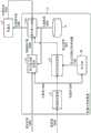
图31是表示实施方式8所涉及的机器人控制装置1e的结构例的图。机器人控制装置1e是在实施方式1所涉及的机器人控制装置1(参照图2)中追加有学习部20的结构。在图31中,对与实施方式1所涉及的机器人控制装置1相同的结构要素标注同一标号。在本实施方式中对与实施方式1不同的部分进行说明。FIG. 31 is a diagram showing a configuration example of a
图32是表示实施方式8所涉及的机器人控制装置1e的学习部20的结构例的图。学习部20具有评价部21及加权系数决定部22。向学习部20输入针对各外界传感器SENk的校正信息1003(ΔXck)、可靠度1006(Pc(k))、加权系数1101和作业信息1110。作业信息1110是使机器人系统100试行作业的结果,或者表示通过仿真模拟出的作业的结果的作业结果信息,包含作业是否成功及作业时间。加权系数1101是构成如果输入校正信息1003及可靠度1006则将轨道校正量1004进行输出的函数的加权系数。FIG. 32 is a diagram showing a configuration example of the
在学习部20中,评价部21基于作业信息1110,通过校正信息1003、可靠度1006及加权系数1101,进行将作业成功率高、作业时间短的作业作为高评价的机器学习。即,评价部21对成为更高的评价的校正信息1003、可靠度1006及加权系数1101的组合进行学习。加权系数决定部22从通过评价部21进行的评价高的加权系数的多个组对1组进行选择,作为学习后的加权系数1102而输出至校正指令值运算部12。校正指令值运算部12对学习部20的学习结果,即,学习后的加权系数1102进行保存,如果存在新校正信息1003及特征量1005的输入,则基于输入的校正信息1003及特征量1005和保存的学习后的加权系数1102,对轨道校正量1004进行计算。In the
在这里,加权系数是为了通过将可靠度Pc(k)和校正信息ΔXck作为输入,将轨道校正量ΔXd进行输出的关系式表示而定义出的。在将该加权系数定义为wck的情况下,轨道校正量ΔXd例如按照下面的式(19)进行计算。加权系数wck是将可靠度设为变量的多项式等适当的函数。Here, the weighting coefficients are defined in order to express the relational expression which takes the reliability Pc(k) and the correction information ΔXck as input, and outputs the orbit correction amount ΔXd. When this weighting coefficient is defined as wck, the orbit correction amount ΔXd is calculated according to the following equation (19), for example. The weighting coefficient wck is an appropriate function such as a polynomial with reliability as a variable.
ΔXd=Σ(wck·ΔXck)…(19)ΔXd=Σ(wck·ΔXck)...(19)
对如上所述的加权系数与生产节拍时间及作业成功与否的信息的因果关系进行分析一般是困难的,但实施仿真或者实际的作业而取得大量的作业信息1110,使用机器学习进行学习,由此能够自动地决定适当的加权系数。It is generally difficult to analyze the causal relationship between the above-mentioned weighting coefficients, takt time, and job success information. However, a large amount of job information 1110 is obtained by performing simulation or actual work, and learning is performed using machine learning. This enables automatic determination of appropriate weighting coefficients.
此外,在本实施方式中,对学习部20存在于机器人控制装置1e的内部进行了说明,但也可以是学习部20存在于机器人控制装置1e的外部例如外部的计算机内的方式。在该情况下,学习部20在机器学习完成后,将通过机器学习取得的学习后的加权系数1102设置于机器人控制装置1e的校正指令值运算部12。In addition, in this embodiment, the
根据以上的结构,通常关于关系性繁琐而难以求出的加权系数wck,能够使用机器学习而决定更有效的加权系数wck。因此,能够进行作业成功率高、作业时间短的调整。作为结果,得到能够提高生产系统的生产效率的效果。According to the above configuration, it is possible to determine a more effective weighting coefficient wck using machine learning for the weighting coefficient wck whose relationship is complicated and difficult to obtain normally. Therefore, it is possible to perform adjustment with a high work success rate and short work time. As a result, there is an effect that the production efficiency of the production system can be improved.
此外,在本实施方式中,对在实施方式1所涉及的机器人控制装置1中追加有学习部20的结构进行了说明,但也能够构成为在实施方式2~7所说明的机器人控制装置中追加有学习部20。In addition, in the present embodiment, the structure in which the
实施方式9.Implementation mode 9.
图33是表示实施方式9所涉及的机器人控制装置1f的结构例的图。机器人控制装置1f是在实施方式3所涉及的机器人控制装置1a(参照图15)中追加有学习部30的结构。在图33中,对与实施方式3所涉及的机器人控制装置1a相同的结构要素标注同一标号。在本实施方式中对与实施方式3不同的部分进行说明。FIG. 33 is a diagram showing a configuration example of a
图34是表示实施方式9所涉及的机器人控制装置1f的学习部30的结构例的图。学习部30具有评价部31及校正倍率函数决定部32。向学习部30输入校正倍率函数1103、可靠度1006(Pc(k))、加权系数1101和作业信息1110。这些可靠度1006(Pc(k))、加权系数1101及作业信息1110与在实施方式8中说明的向学习部20输入的可靠度1006(Pc(k))、加权系数1101及作业信息1110相同。FIG. 34 is a diagram showing a configuration example of the
在学习部30中,评价部31基于作业信息1110,通过机器学习而获得作业时间短、作业成功率高的校正倍率函数1103。In the
在这里,校正倍率函数是关于可靠度Pc(k)和校正倍率之间的关系性定义出的。校正倍率函数决定部32关于校正倍率函数,在通过某加权系数1101定义出的指令值生成部13a的处理中,关于最提高作业成功率并作业时间变得最短的校正倍率的函数定义进行选定,将其结果作为学习后的校正倍率函数1104而输出至校正倍率运算部15。校正倍率运算部15对学习部30的学习结果、即学习后的校正倍率函数1104进行保存,如果存在新的可靠度1006的输入,则基于输入的可靠度1006和保存的学习后的校正倍率函数1104对校正倍率1007进行计算。Here, the correction magnification function is defined with respect to the relationship between the reliability Pc(k) and the correction magnification. The correction magnification function determination unit 32 selects the function definition of the correction magnification that maximizes the work success rate and minimizes the work time in the process of the command
例如,校正倍率函数1104存在有在实施方式3及4中如算式(14)、算式(15)及算式(16)中例示出的定义的方式。特别地,在存在加权系数1101的情况下,校正倍率运算部15将与传感器信号Sk相对应的多个校正倍率OvrdC(k)进行输出,在指令值生成部13a中,有时采取对校正信息ΔXck之中的向轨道校正量ΔXd的比例最大的信息所对应的校正倍率OvrdC(k)进行选择的方法。因此,校正倍率函数1104需要作为与加权系数1101及可靠度1006有关的2个函数进行定义。在学习部30的学习处理中,使用仿真或者实机对作为这些函数而定义的多项式等各种变化进行试行,将其结果输入至学习部30。作为结果,对评价值变得最高的结果进行选择,能够作为学习后的校正倍率函数进行输出。For example, the
此外,在本实施方式中,对学习部30存在于机器人控制装置1f的内部进行了说明,但也可以是学习部30存在于机器人控制装置1f的外部例如外部的计算机内的方式。在该情况下,学习部30在机器学习完成后,将通过机器学习取得的学习后的校正倍率函数1104设置于机器人控制装置1f的校正倍率运算部15。In addition, in this embodiment, the
通过具有以上的结构,从而关于如校正倍率函数那样的通常关系性繁琐而难以求出的函数表现,能够使用机器学习而决定更有效的函数表现。作为结果,能够进行作业成功率高、作业时间短的调整,得到能够提高生产系统的生产效率的效果。With the above configuration, machine learning can be used to determine a more effective function expression for a function expression that is usually difficult to obtain because of complicated relationships, such as a correction factor function. As a result, it is possible to perform adjustments with a high work success rate and a short work time, thereby obtaining an effect that the production efficiency of the production system can be improved.
此外,在本实施方式中,对在实施方式3所涉及的机器人控制装置1a中追加了学习部30的结构进行了说明,但也能够构成为在实施方式4~6所说明的各机器人控制装置、即具有校正倍率运算部的机器人控制装置中追加有学习部30。In addition, in this embodiment, the structure in which the
以上的实施方式所示的结构表示一个例子,也能够与其他公知技术组合,也能够将实施方式彼此组合,在不脱离主旨的范围也能够将结构的一部分省略、变更。The configuration shown in the above embodiments is an example, and it can be combined with other known techniques, and the embodiments can be combined, and a part of the configuration can be omitted or changed without departing from the gist.
标号的说明Explanation of labels
1、1a、1b、1c、1d、1e、1f机器人控制装置,2机器人,3外界传感器,4传感器控制器,11、11d可靠度运算部,12校正指令值运算部,13、13a指令值生成部,14目标轨道保存部,15、15b校正倍率运算部,16特征量提取部,20、30学习部,21、31评价部,22加权系数决定部,32校正倍率函数决定部,100机器人系统,201力觉传感器,202-1、202-2视觉传感器,203-1视野,300物体。1, 1a, 1b, 1c, 1d, 1e, 1f robot control device, 2 robots, 3 external sensors, 4 sensor controllers, 11, 11d reliability calculation unit, 12 correction command value calculation unit, 13, 13a command value generation Section, 14 Target Orbit Preservation Section, 15, 15b Correction Magnification Calculation Section, 16 Feature Extraction Section, 20, 30 Learning Section, 21, 31 Evaluation Section, 22 Weighting Coefficient Decision Section, 32 Correction Magnification Function Decision Section, 100 Robot System , 201 force sensor, 202-1, 202-2 vision sensor, 203-1 field of view, 300 objects.
Claims (9)
Applications Claiming Priority (1)
| Application Number | Priority Date | Filing Date | Title |
|---|---|---|---|
| PCT/JP2020/034761WO2022054292A1 (en) | 2020-09-14 | 2020-09-14 | Robot control device |
Publications (2)
| Publication Number | Publication Date |
|---|---|
| CN116075399Atrue CN116075399A (en) | 2023-05-05 |
| CN116075399B CN116075399B (en) | 2024-11-12 |
Family
ID=80631748
Family Applications (1)
| Application Number | Title | Priority Date | Filing Date |
|---|---|---|---|
| CN202080102469.XAActiveCN116075399B (en) | 2020-09-14 | 2020-09-14 | Robot control device |
Country Status (5)
| Country | Link |
|---|---|
| US (1) | US12220821B2 (en) |
| JP (1) | JP7301238B2 (en) |
| CN (1) | CN116075399B (en) |
| DE (1) | DE112020007606B4 (en) |
| WO (1) | WO2022054292A1 (en) |
Families Citing this family (3)
| Publication number | Priority date | Publication date | Assignee | Title |
|---|---|---|---|---|
| US20240139961A1 (en)* | 2022-11-02 | 2024-05-02 | Intrinsic Innovation Llc | Real-time robotic end effector control |
| US20240248458A1 (en)* | 2023-01-24 | 2024-07-25 | Google Llc | On-Robot Data Collection |
| JP2024146638A (en)* | 2023-03-31 | 2024-10-15 | 株式会社Thinker | Proximity sensor and robot system using same |
Citations (5)
| Publication number | Priority date | Publication date | Assignee | Title |
|---|---|---|---|---|
| JPH07266272A (en)* | 1994-03-29 | 1995-10-17 | Nippon Telegr & Teleph Corp <Ntt> | Tracking method and device for manipulator |
| CN101473658A (en)* | 2006-06-22 | 2009-07-01 | 奥林巴斯株式会社 | Imaging system and imaging program |
| CN103402838A (en)* | 2011-03-02 | 2013-11-20 | 大陆-特韦斯贸易合伙股份公司及两合公司 | Intelligent vehicle sensor device |
| CN106028932A (en)* | 2013-12-16 | 2016-10-12 | 美敦力迷你迈德公司 | Method and system for improving reliability of quadrature redundant sensors |
| US20160379121A1 (en)* | 2015-06-24 | 2016-12-29 | Baidu Online Network Technology (Beijing) Co., Ltd. | Control system, method and device of intelligent robot based on artificial intelligence |
Family Cites Families (26)
| Publication number | Priority date | Publication date | Assignee | Title |
|---|---|---|---|---|
| JP2708458B2 (en)* | 1988-04-01 | 1998-02-04 | 株式会社豊田中央研究所 | Copy control robot |
| EP0353585A3 (en) | 1988-08-04 | 1992-04-22 | Siemens Aktiengesellschaft | Method to correct path and position of a robot tool |
| US4945493A (en) | 1988-09-26 | 1990-07-31 | Ford Motor Company | Method and system for correcting a robot path |
| EP0696775A1 (en)* | 1993-04-21 | 1996-02-14 | Hitachi, Ltd. | Computer-aided design and production system for component arrangement and pipe routing |
| DE69637413T2 (en)* | 1995-12-27 | 2009-01-22 | Fanuc Ltd. | COMPOSITE DETECTION SYSTEM FOR ROBOTS |
| US6611755B1 (en)* | 1999-12-19 | 2003-08-26 | Trimble Navigation Ltd. | Vehicle tracking, communication and fleet management system |
| JP3994950B2 (en)* | 2003-09-19 | 2007-10-24 | ソニー株式会社 | Environment recognition apparatus and method, path planning apparatus and method, and robot apparatus |
| US7425829B2 (en)* | 2003-10-14 | 2008-09-16 | Merlin Technology, Inc. | Tracking positions of personnel, vehicles, and inanimate objects |
| JP2005199403A (en) | 2004-01-16 | 2005-07-28 | Sony Corp | Emotion recognition device and method, emotion recognition method of robot device, learning method of robot device and robot device |
| JP5306313B2 (en)* | 2010-12-20 | 2013-10-02 | 株式会社東芝 | Robot controller |
| US8886359B2 (en)* | 2011-05-17 | 2014-11-11 | Fanuc Corporation | Robot and spot welding robot with learning control function |
| US9279661B2 (en)* | 2011-07-08 | 2016-03-08 | Canon Kabushiki Kaisha | Information processing apparatus and information processing method |
| WO2013027251A1 (en)* | 2011-08-19 | 2013-02-28 | 株式会社安川電機 | Robot system, robot control device, robot hand and method for controlling robot |
| JP5774223B2 (en) | 2012-06-29 | 2015-09-09 | 三菱電機株式会社 | Robot control apparatus and robot control method |
| US10556345B2 (en)* | 2014-02-28 | 2020-02-11 | Sony Corporation | Robot arm apparatus and calibration method |
| JP7345237B2 (en)* | 2014-11-05 | 2023-09-15 | シエラ・ネバダ・コーポレイション | System and method for generating improved environmental representations for mobile objects |
| DE102014017307B4 (en) | 2014-11-21 | 2019-08-01 | Kuka Roboter Gmbh | Method and system for processing a component with a robot-guided tool |
| WO2016122416A1 (en) | 2015-01-30 | 2016-08-04 | Agency for Science,Technology and Research | Mobile manipulator and method of controlling the mobile manipulator for tracking a surface |
| US9889566B2 (en)* | 2015-05-01 | 2018-02-13 | General Electric Company | Systems and methods for control of robotic manipulation |
| US11020859B2 (en)* | 2015-05-01 | 2021-06-01 | Transportation Ip Holdings, Llc | Integrated robotic system and method for autonomous vehicle maintenance |
| WO2017033365A1 (en) | 2015-08-25 | 2017-03-02 | 川崎重工業株式会社 | Remote control robot system |
| US10854104B2 (en)* | 2015-08-28 | 2020-12-01 | Icuemotion Llc | System for movement skill analysis and skill augmentation and cueing |
| JP2017124470A (en)* | 2016-01-14 | 2017-07-20 | セイコーエプソン株式会社 | Robot and robot system |
| CA3071332A1 (en)* | 2017-07-25 | 2019-01-31 | Mbl Limited | Systems and methods for operations a robotic system and executing robotic interactions |
| US11510736B2 (en)* | 2017-12-14 | 2022-11-29 | Auris Health, Inc. | System and method for estimating instrument location |
| JP6816060B2 (en)* | 2018-04-23 | 2021-01-20 | ファナック株式会社 | Work robot system and work robot |
- 2020
- 2020-09-14JPJP2022547375Apatent/JP7301238B2/enactiveActive
- 2020-09-14WOPCT/JP2020/034761patent/WO2022054292A1/ennot_activeCeased
- 2020-09-14USUS18/010,810patent/US12220821B2/enactiveActive
- 2020-09-14CNCN202080102469.XApatent/CN116075399B/enactiveActive
- 2020-09-14DEDE112020007606.7Tpatent/DE112020007606B4/enactiveActive
Patent Citations (5)
| Publication number | Priority date | Publication date | Assignee | Title |
|---|---|---|---|---|
| JPH07266272A (en)* | 1994-03-29 | 1995-10-17 | Nippon Telegr & Teleph Corp <Ntt> | Tracking method and device for manipulator |
| CN101473658A (en)* | 2006-06-22 | 2009-07-01 | 奥林巴斯株式会社 | Imaging system and imaging program |
| CN103402838A (en)* | 2011-03-02 | 2013-11-20 | 大陆-特韦斯贸易合伙股份公司及两合公司 | Intelligent vehicle sensor device |
| CN106028932A (en)* | 2013-12-16 | 2016-10-12 | 美敦力迷你迈德公司 | Method and system for improving reliability of quadrature redundant sensors |
| US20160379121A1 (en)* | 2015-06-24 | 2016-12-29 | Baidu Online Network Technology (Beijing) Co., Ltd. | Control system, method and device of intelligent robot based on artificial intelligence |
Also Published As
| Publication number | Publication date |
|---|---|
| US12220821B2 (en) | 2025-02-11 |
| JPWO2022054292A1 (en) | 2022-03-17 |
| WO2022054292A1 (en) | 2022-03-17 |
| DE112020007606B4 (en) | 2024-06-13 |
| US20230286150A1 (en) | 2023-09-14 |
| CN116075399B (en) | 2024-11-12 |
| JP7301238B2 (en) | 2023-06-30 |
| DE112020007606T5 (en) | 2023-06-29 |
Similar Documents
| Publication | Publication Date | Title |
|---|---|---|
| Xu et al. | Compare contact model-based control and contact model-free learning: A survey of robotic peg-in-hole assembly strategies | |
| CN108873768B (en) | Task execution system and method, learning device and method, and recording medium | |
| US11745355B2 (en) | Control device, control method, and non-transitory computer-readable storage medium | |
| US12090673B2 (en) | Control apparatus, control method, and computer-readable storage medium storing a control program | |
| US12097616B2 (en) | Model generation apparatus, model generation method, control apparatus, and control method | |
| US10940585B2 (en) | Vibration suppression device | |
| CN116075399A (en) | robot controller | |
| JP7376318B2 (en) | annotation device | |
| EP4400274A1 (en) | Command value generating device, method, and program | |
| JP7263987B2 (en) | Control device, control method, and control program | |
| WO2021033471A1 (en) | Control device, control method, and control program | |
| US10962957B2 (en) | Collision position estimation device and machine learning device | |
| US20240139962A1 (en) | Iterative control of robot for target object | |
| KR20240057354A (en) | Method and apparatus for 6dof object pose estimation using self-supervision learning | |
| JP7647862B2 (en) | Learning device, learning method, and program | |
| US20230286143A1 (en) | Robot control in working space | |
| CN117693416A (en) | Teaching robotic systems using gesture control and visual inertial odometer | |
| US20250178205A1 (en) | Robot system, method of controlling the robot system, method of manufacturing products, and recording medium | |
| US20240131699A1 (en) | Robot system, learning apparatus, information processing apparatus, learned model, control method, information processing method, method for manufacturing product, and recording medium | |
| Jimoh et al. | Multi-Temporal Predictive Coding for Robotic Arm Control | |
| Shaar et al. | Optimizing Robot Motion: A Practical Control for Accurate and Low Energy-Consumption Industrial Manipulator | |
| CN118192372A (en) | Robot information processing method for man-machine interaction | |
| CN118288281A (en) | Control method, device, equipment and storage medium for robot constant force deburring |
Legal Events
| Date | Code | Title | Description |
|---|---|---|---|
| PB01 | Publication | ||
| PB01 | Publication | ||
| SE01 | Entry into force of request for substantive examination | ||
| SE01 | Entry into force of request for substantive examination | ||
| GR01 | Patent grant | ||
| GR01 | Patent grant |