CN116075334A - Stationary equipment for intracardiac blood pump systems - Google Patents
Stationary equipment for intracardiac blood pump systemsDownload PDFInfo
- Publication number
- CN116075334A CN116075334ACN202180058275.9ACN202180058275ACN116075334ACN 116075334 ACN116075334 ACN 116075334ACN 202180058275 ACN202180058275 ACN 202180058275ACN 116075334 ACN116075334 ACN 116075334A
- Authority
- CN
- China
- Prior art keywords
- housing
- fixation device
- button
- sheath
- sheath assembly
- Prior art date
- Legal status (The legal status is an assumption and is not a legal conclusion. Google has not performed a legal analysis and makes no representation as to the accuracy of the status listed.)
- Pending
Links
Images


Classifications
- A—HUMAN NECESSITIES
- A61—MEDICAL OR VETERINARY SCIENCE; HYGIENE
- A61M—DEVICES FOR INTRODUCING MEDIA INTO, OR ONTO, THE BODY; DEVICES FOR TRANSDUCING BODY MEDIA OR FOR TAKING MEDIA FROM THE BODY; DEVICES FOR PRODUCING OR ENDING SLEEP OR STUPOR
- A61M39/00—Tubes, tube connectors, tube couplings, valves, access sites or the like, specially adapted for medical use
- A61M39/02—Access sites
- A61M39/06—Haemostasis valves, i.e. gaskets sealing around a needle, catheter or the like, closing on removal thereof
- A61M39/0613—Haemostasis valves, i.e. gaskets sealing around a needle, catheter or the like, closing on removal thereof with means for adjusting the seal opening or pressure
- A—HUMAN NECESSITIES
- A61—MEDICAL OR VETERINARY SCIENCE; HYGIENE
- A61M—DEVICES FOR INTRODUCING MEDIA INTO, OR ONTO, THE BODY; DEVICES FOR TRANSDUCING BODY MEDIA OR FOR TAKING MEDIA FROM THE BODY; DEVICES FOR PRODUCING OR ENDING SLEEP OR STUPOR
- A61M60/00—Blood pumps; Devices for mechanical circulatory actuation; Balloon pumps for circulatory assistance
- A61M60/80—Constructional details other than related to driving
- A61M60/855—Constructional details other than related to driving of implantable pumps or pumping devices
- A61M60/865—Devices for guiding or inserting pumps or pumping devices into the patient's body
- A—HUMAN NECESSITIES
- A61—MEDICAL OR VETERINARY SCIENCE; HYGIENE
- A61M—DEVICES FOR INTRODUCING MEDIA INTO, OR ONTO, THE BODY; DEVICES FOR TRANSDUCING BODY MEDIA OR FOR TAKING MEDIA FROM THE BODY; DEVICES FOR PRODUCING OR ENDING SLEEP OR STUPOR
- A61M39/00—Tubes, tube connectors, tube couplings, valves, access sites or the like, specially adapted for medical use
- A61M39/02—Access sites
- A61M39/06—Haemostasis valves, i.e. gaskets sealing around a needle, catheter or the like, closing on removal thereof
- A—HUMAN NECESSITIES
- A61—MEDICAL OR VETERINARY SCIENCE; HYGIENE
- A61M—DEVICES FOR INTRODUCING MEDIA INTO, OR ONTO, THE BODY; DEVICES FOR TRANSDUCING BODY MEDIA OR FOR TAKING MEDIA FROM THE BODY; DEVICES FOR PRODUCING OR ENDING SLEEP OR STUPOR
- A61M39/00—Tubes, tube connectors, tube couplings, valves, access sites or the like, specially adapted for medical use
- A61M39/10—Tube connectors; Tube couplings
- A—HUMAN NECESSITIES
- A61—MEDICAL OR VETERINARY SCIENCE; HYGIENE
- A61M—DEVICES FOR INTRODUCING MEDIA INTO, OR ONTO, THE BODY; DEVICES FOR TRANSDUCING BODY MEDIA OR FOR TAKING MEDIA FROM THE BODY; DEVICES FOR PRODUCING OR ENDING SLEEP OR STUPOR
- A61M60/00—Blood pumps; Devices for mechanical circulatory actuation; Balloon pumps for circulatory assistance
- A61M60/10—Location thereof with respect to the patient's body
- A61M60/122—Implantable pumps or pumping devices, i.e. the blood being pumped inside the patient's body
- A61M60/165—Implantable pumps or pumping devices, i.e. the blood being pumped inside the patient's body implantable in, on, or around the heart
- A61M60/17—Implantable pumps or pumping devices, i.e. the blood being pumped inside the patient's body implantable in, on, or around the heart inside a ventricle, e.g. intraventricular balloon pumps
- A—HUMAN NECESSITIES
- A61—MEDICAL OR VETERINARY SCIENCE; HYGIENE
- A61M—DEVICES FOR INTRODUCING MEDIA INTO, OR ONTO, THE BODY; DEVICES FOR TRANSDUCING BODY MEDIA OR FOR TAKING MEDIA FROM THE BODY; DEVICES FOR PRODUCING OR ENDING SLEEP OR STUPOR
- A61M39/00—Tubes, tube connectors, tube couplings, valves, access sites or the like, specially adapted for medical use
- A61M39/02—Access sites
- A61M39/06—Haemostasis valves, i.e. gaskets sealing around a needle, catheter or the like, closing on removal thereof
- A61M2039/062—Haemostasis valves, i.e. gaskets sealing around a needle, catheter or the like, closing on removal thereof used with a catheter
- A—HUMAN NECESSITIES
- A61—MEDICAL OR VETERINARY SCIENCE; HYGIENE
- A61M—DEVICES FOR INTRODUCING MEDIA INTO, OR ONTO, THE BODY; DEVICES FOR TRANSDUCING BODY MEDIA OR FOR TAKING MEDIA FROM THE BODY; DEVICES FOR PRODUCING OR ENDING SLEEP OR STUPOR
- A61M39/00—Tubes, tube connectors, tube couplings, valves, access sites or the like, specially adapted for medical use
- A61M39/02—Access sites
- A61M39/06—Haemostasis valves, i.e. gaskets sealing around a needle, catheter or the like, closing on removal thereof
- A61M2039/0673—Haemostasis valves, i.e. gaskets sealing around a needle, catheter or the like, closing on removal thereof comprising means actively pressing on the device passing through the seal, e.g. inflatable seals, diaphragms, clamps
- A—HUMAN NECESSITIES
- A61—MEDICAL OR VETERINARY SCIENCE; HYGIENE
- A61M—DEVICES FOR INTRODUCING MEDIA INTO, OR ONTO, THE BODY; DEVICES FOR TRANSDUCING BODY MEDIA OR FOR TAKING MEDIA FROM THE BODY; DEVICES FOR PRODUCING OR ENDING SLEEP OR STUPOR
- A61M39/00—Tubes, tube connectors, tube couplings, valves, access sites or the like, specially adapted for medical use
- A61M39/10—Tube connectors; Tube couplings
- A61M2039/1033—Swivel nut connectors, e.g. threaded connectors, bayonet-connectors
- A—HUMAN NECESSITIES
- A61—MEDICAL OR VETERINARY SCIENCE; HYGIENE
- A61M—DEVICES FOR INTRODUCING MEDIA INTO, OR ONTO, THE BODY; DEVICES FOR TRANSDUCING BODY MEDIA OR FOR TAKING MEDIA FROM THE BODY; DEVICES FOR PRODUCING OR ENDING SLEEP OR STUPOR
- A61M39/00—Tubes, tube connectors, tube couplings, valves, access sites or the like, specially adapted for medical use
- A61M39/10—Tube connectors; Tube couplings
- A61M2039/1066—Tube connectors; Tube couplings having protection means, e.g. sliding sleeve to protect connector itself, shrouds to protect a needle present in the connector, protective housing, isolating sheath
Landscapes
- Health & Medical Sciences (AREA)
- Heart & Thoracic Surgery (AREA)
- Engineering & Computer Science (AREA)
- Animal Behavior & Ethology (AREA)
- Public Health (AREA)
- Biomedical Technology (AREA)
- Hematology (AREA)
- Life Sciences & Earth Sciences (AREA)
- Veterinary Medicine (AREA)
- General Health & Medical Sciences (AREA)
- Anesthesiology (AREA)
- Cardiology (AREA)
- Pulmonology (AREA)
- Mechanical Engineering (AREA)
- Surgical Instruments (AREA)
- Infusion, Injection, And Reservoir Apparatuses (AREA)
- External Artificial Organs (AREA)
- Media Introduction/Drainage Providing Device (AREA)
Abstract
Translated fromChinese
Description
Translated fromChinese相关申请的交叉引用Cross References to Related Applications
本申请要求于2020年7月29日提交的美国临时申请第63/058,003号的优先权,该申请的全部内容通过引用并入本文。This application claims priority to U.S. Provisional Application No. 63/058,003, filed July 29, 2020, which is incorporated herein by reference in its entirety.
背景技术Background technique
心内心脏泵组件可以通过外科手术或经皮被引入心脏中并用于将血液从心脏或循环系统中的一个位置输送到心脏或循环系统中的另一个位置。例如,当部署在心脏中时,心内泵可以将血液从心脏的左心室泵入主动脉,或将血液从下腔静脉泵入肺动脉。心内泵可以由位于患者体外的马达(以及随附的驱动电缆)或通过位于患者体内的机载马达提供动力。一些心内血泵系统可以与自身心脏并行运行以补充心输出量并部分或完全卸载心脏的成分。此类系统的示例包括
在一种常见的方法中,心内血泵通过导管插入术使用鞘(例如,剥离式导引器鞘)通过股动脉插入。鞘可以可替代地插入其它位置,例如股静脉或用于输送用于支撑心脏的左侧或右侧的泵的任何路径中。In one common approach, an intracardiac blood pump is inserted through the femoral artery by catheterization using a sheath (eg, a peel-off introducer sheath). The sheath may alternatively be inserted in other locations such as the femoral vein or any route used to deliver pumps supporting the left or right side of the heart.
可以通过动脉切开术将导引器鞘插入股动脉中以创建用于泵组件的插入路径。然后将泵组件的一部分推进通过导引器的内管腔并进入动脉。在一些情况下,一旦插入了泵组件,就可以将较窄的重定位鞘插入导引器鞘中,并且可以剥离导引器鞘。重定位鞘可以配备有用于将重定位鞘组件固定至到患者的结构。例如,重定位鞘组件的近侧毂可以具有可以缝合到患者皮肤上的蝶形结构。An introducer sheath may be inserted into the femoral artery through an arteriotomy to create an insertion path for the pump assembly. A portion of the pump assembly is then advanced through the inner lumen of the introducer and into the artery. In some cases, once the pump assembly is inserted, the narrower repositioning sheath can be inserted into the introducer sheath, and the introducer sheath can be peeled off. The repositioning sheath may be equipped with features for securing the repositioning sheath assembly to the patient. For example, the proximal hub of the repositioning sheath assembly can have a butterfly configuration that can be sutured to the patient's skin.
在一些情况下,即使在泵组件已插入后,导引器鞘仍可能保持在原位。在这样的情况下,除了导引器鞘外,可能会或可能不会使用重定位鞘。在使用重定位鞘的情况下,它可以例如插入导引器鞘内。在一些情况下,重定位鞘可以被配置为装配在导引器鞘的管腔内。在一些情况下,导引器鞘的管腔可以被配置为扩张以允许将重定位鞘插入其中。在一些情况下,导引器鞘可以被配置为使得重定位鞘不被插入到导引器鞘的管腔中。在导引器鞘仍保持在原位的情况下,它还可以配备有用于将导引器鞘组件固定至患者的结构(例如,缝合蝶形件)。In some cases, the introducer sheath may remain in place even after the pump assembly has been inserted. In such cases, a repositioning sheath may or may not be used in addition to the introducer sheath. Where a repositioning sheath is used, it can eg be inserted into the introducer sheath. In some cases, the repositioning sheath can be configured to fit within the lumen of the introducer sheath. In some cases, the lumen of the introducer sheath can be configured to expand to allow insertion of the repositioning sheath therein. In some cases, the introducer sheath can be configured such that the repositioning sheath is not inserted into the lumen of the introducer sheath. With the introducer sheath still in place, it may also be equipped with structures (eg, suture butterflies) for securing the introducer sheath assembly to the patient.
无论插入泵组件后导引器鞘、重定位鞘或两者是否仍在使用,都可以使用固定设备将泵组件的导管相对于其已插入通过的(一个或多个)鞘进行固定。例如,Tuohy-Borst设备可以附接或合并到导引器鞘或重定位鞘的毂中。沿一个方向转动Tuohy-Borst设备的筒体会压缩可变形的内部部件(例如,可变形的环或套筒),这因此可用于形成对泵组件导管的密封并阻止导管在Tuohy-Borst设备内移动。沿另一个方向转动Tuohy-Borst设备的筒体可使可变形的内部部件松弛,从而允许导管移动。然而,由于Tuohy-Borst设备不会限制导管的移动而无需操作员有意采取行动,因此可能会无意中将其留在打开或半打开位置。同样,因为Tuohy-Borst设备可以提供可变大小的阻力,所以操作员可能会意外地将它拧得不够紧或者它可能会无意中松开(例如,由于患者的移动),从而使导管已被放置在其期望位置后移动。Whether the introducer sheath, the repositioning sheath, or both are still in use after insertion of the pump assembly, a fixation device may be used to secure the catheter of the pump assembly relative to the sheath(s) through which it has been inserted. For example, a Tuohy-Borst device may be attached or incorporated into the hub of an introducer sheath or repositioning sheath. Turning the barrel of the Tuohy-Borst device in one direction compresses the deformable inner component (eg, a deformable ring or sleeve), which can thus be used to form a seal against the pump assembly conduit and prevent the conduit from moving within the Tuohy-Borst device . Turning the barrel of the Tuohy-Borst device in the other direction relaxes the deformable inner part, allowing the catheter to move. However, because the Tuohy-Borst device does not restrict catheter movement without deliberate operator action, it may be left in the open or semi-open position inadvertently. Also, because the Tuohy-Borst device can provide variable amounts of resistance, the operator may accidentally undertighten it or it may unintentionally loosen (for example, due to patient movement), leaving the catheter already in place. Move after being placed in its desired location.
发明内容Contents of the invention
本技术涉及用于与心内血泵组件一起使用的改进的固定设备。更具体地,本技术提供了固定设备,所述固定设备可以与鞘组件(例如,导引器鞘组件、重定位鞘组件)一起使用,并且被配置为限制泵组件的导管在鞘组件内移动,除非当固定设备的机构(例如,按钮)正在被主动致动(例如,按下、保持等)时。如将在下面进一步详细解释的,本技术的固定设备可以提供为模块化单元,其可以附接到导引器鞘或重定位鞘组件的毂或止血阀。同样,本技术的固定设备也可以提供为止血阀的组成部分,或者提供为导引器鞘组件或重定位鞘组件的组成部分。The present technology relates to improved fixation devices for use with intracardiac blood pump assemblies. More specifically, the present technology provides fixation devices that may be used with sheath assemblies (e.g., introducer sheath assemblies, repositioning sheath assemblies) and are configured to restrict movement of the catheter of the pump assembly within the sheath assembly , except when the mechanism (eg, button) of the securing device is being actively actuated (eg, pressed, held, etc.). As will be explained in further detail below, the fixation devices of the present technology can be provided as a modular unit that can be attached to the hub of an introducer sheath or repositioning sheath assembly or a hemostatic valve. Likewise, fixation devices of the present technology may also be provided as part of a hemostatic valve, or as part of an introducer sheath assembly or a repositioning sheath assembly.
在一个方面,本公开描述了一种用于固定静脉内医疗设备的设备,其包括:(i)具有第一管腔的柔性套筒,所述第一管腔被配置为接收所述静脉内医疗设备的至少一部分;(ii)具有孔的按钮,所述孔被配置为接收所述柔性套筒的至少一部分;(iii)弹簧元件;和(iv)外壳,其包括:第二管腔,其被配置为容纳所述柔性套筒;以及空腔,其被配置为容纳所述按钮和所述弹簧元件,其中所述弹簧元件被配置为在所述按钮上施加力,所述力倾向于导致所述孔压缩所述柔性套筒,除非所述按钮被保持在按下状态。在一些方面,所述外壳包括带有至少一个孔眼的至少一个突出物,所述至少一个突出物被配置为使所述外壳能够被缝合到患者的皮肤上。在一些方面,所述外壳还包括止血阀。在一些方面,所述外壳被配置为与止血阀联接。在一些方面,所述外壳包括至少一个狭槽,所述至少一个狭槽被配置为当所述外壳与所述止血阀联接时接纳所述止血阀的至少一个栓钉。在一些方面,所述至少一个狭槽和所述至少一个栓钉包括卡口连接。在一些方面,所述至少一个狭槽还包括至少一个孔眼,所述至少一个孔眼被配置为与所述至少一个栓钉接合。在一些方面,所述至少一个狭槽还包括至少一个棘爪,所述至少一个棘爪被配置为与所述至少一个栓钉接合。在一些方面,所述外壳还包括密封件,所述密封件被配置为当所述外壳与所述止血阀联接时变形。In one aspect, the present disclosure describes an apparatus for securing an intravenous medical device comprising: (i) a flexible sleeve having a first lumen configured to receive the intravenous at least a portion of a medical device; (ii) a button having an aperture configured to receive at least a portion of the flexible sleeve; (iii) a spring element; and (iv) a housing comprising: a second lumen, which is configured to accommodate the flexible sleeve; and a cavity configured to accommodate the button and the spring element, wherein the spring element is configured to exert a force on the button which tends to The aperture is caused to compress the flexible sleeve unless the button is held in a depressed state. In some aspects, the housing includes at least one protrusion with at least one eyelet configured to enable the housing to be sutured to the patient's skin. In some aspects, the housing also includes a hemostatic valve. In some aspects, the housing is configured to couple with a hemostatic valve. In some aspects, the housing includes at least one slot configured to receive at least one peg of the hemostatic valve when the housing is coupled with the hemostatic valve. In some aspects, the at least one slot and the at least one peg comprise a bayonet connection. In some aspects, the at least one slot further includes at least one eyelet configured to engage the at least one peg. In some aspects, the at least one slot further includes at least one detent configured to engage the at least one peg. In some aspects, the housing further includes a seal configured to deform when the housing is coupled with the hemostatic valve.
另一方面,本公开描述了一种鞘组件,其包括:(a)鞘主体,其被配置用于插入到患者的脉管系统中,并且被配置为接收静脉内医疗设备的至少一部分;(b)鞘毂,其被联接到所述鞘主体的近端;和(c)固定设备,其与所述鞘毂集成或被配置为与所述鞘毂联接,所述固定设备包括:(i)具有第一管腔的柔性套筒,所述第一管腔被配置为接收所述静脉内医疗设备的至少一部分;(ii)具有孔的按钮,所述孔被配置为接收所述柔性套筒的至少一部分;(iii)弹簧元件;和(iv)外壳,其包括:第二管腔,其被配置为容纳所述柔性套筒;以及空腔,其被配置为容纳所述按钮和所述弹簧元件,其中所述弹簧元件被配置为在所述按钮上施加力,所述力倾向于导致所述孔压缩所述柔性套筒,除非所述按钮被保持在按下状态。在一些方面,所述固定设备的所述外壳包括带有至少一个孔眼的至少一个突出物,所述至少一个突出物被配置为使得所述外壳能够被缝合到患者的皮肤上。在一些方面,所述鞘毂包括具有至少一个孔眼的至少一个突出物,所述至少一个突出物被配置为使得所述鞘毂能够被缝合到患者的皮肤上。在一些方面,所述固定设备的所述外壳还包括止血阀。在一些方面,所述鞘毂还包括止血阀。在一些方面,所述固定设备的所述外壳被配置为与止血阀联接。在一些方面,所述固定设备的所述外壳包括至少一个狭槽,所述至少一个狭槽被配置为当所述固定设备的所述外壳与所述止血阀联接时接纳所述止血阀的至少一个栓钉。在一些方面,所述至少一个狭槽和所述至少一个栓钉包括卡口连接。在一些方面,所述至少一个狭槽还包括至少一个孔眼,所述至少一个孔眼被配置为与所述至少一个栓钉接合。在一些方面,所述至少一个狭槽还包括至少一个棘爪,所述至少一个棘爪被配置为与所述至少一个栓钉接合。在一些方面,所述固定设备的所述外壳还包括密封件,所述密封件被配置为当所述固定设备的所述外壳与所述止血阀联接时变形。In another aspect, the present disclosure describes a sheath assembly comprising: (a) a sheath body configured for insertion into a patient's vasculature and configured to receive at least a portion of an intravenous medical device; ( b) a sheath hub coupled to the proximal end of the sheath body; and (c) a fixation device integrated with or configured to couple with the sheath hub, said fixation device comprising: (i ) a flexible sleeve having a first lumen configured to receive at least a portion of the intravenous medical device; (ii) a button having an aperture configured to receive the flexible sleeve at least a portion of the barrel; (iii) a spring element; and (iv) a housing comprising: a second lumen configured to accommodate the flexible sleeve; and a cavity configured to accommodate the button and the The spring element, wherein the spring element is configured to exert a force on the button that tends to cause the aperture to compress the flexible sleeve unless the button is held in a depressed state. In some aspects, the housing of the fixation device includes at least one protrusion with at least one eyelet configured to enable the housing to be sutured to the patient's skin. In some aspects, the sheath hub includes at least one protrusion having at least one eyelet configured to enable the sheath hub to be sutured to the patient's skin. In some aspects, the housing of the fixation device further includes a hemostatic valve. In some aspects, the sheath hub also includes a hemostatic valve. In some aspects, the housing of the fixation device is configured to couple with a hemostatic valve. In some aspects, the housing of the fixation device includes at least one slot configured to receive at least one of the hemostatic valves when the housing of the fixation device is coupled with the hemostatic valve. a peg. In some aspects, the at least one slot and the at least one peg comprise a bayonet connection. In some aspects, the at least one slot further includes at least one eyelet configured to engage the at least one peg. In some aspects, the at least one slot further includes at least one detent configured to engage the at least one peg. In some aspects, the housing of the fixation device further includes a seal configured to deform when the housing of the fixation device is coupled with the hemostatic valve.
附图说明Description of drawings
图1示出了根据本公开各方面的示例性系统,其包括血泵和重定位鞘组件,以及导引器鞘组件;1 illustrates an exemplary system including a blood pump and repositioning sheath assembly, and an introducer sheath assembly, according to aspects of the present disclosure;
图2示出了图1的血泵和重定位鞘组件的放大图;Figure 2 shows an enlarged view of the blood pump and repositioning sheath assembly of Figure 1;
图3示出了根据本公开各方面的使用示例性按钮致动的固定设备的血泵和重定位鞘组件的放大图;3 illustrates an enlarged view of a blood pump and repositioning sheath assembly using an exemplary button-actuated fixation device in accordance with aspects of the present disclosure;
图4示出了图3的示例性按钮致动的固定设备的三维模型的立体图;Figure 4 shows a perspective view of a three-dimensional model of the exemplary button-actuated fixation device of Figure 3;
图5示出了图3的示例性按钮致动的固定设备的线图;Figure 5 shows a line diagram of the exemplary button-actuated fixation device of Figure 3;
图6示出了图3的示例性按钮致动的固定设备的分解图;Figure 6 shows an exploded view of the exemplary button-actuated fixation device of Figure 3;
图7示出了图3的示例性按钮致动的固定设备的横截面轮廓视图;Figure 7 shows a cross-sectional profile view of the exemplary button-actuated fixation device of Figure 3;
图8示出了根据本公开各方面的使用示例性按钮致动的固定设备的血泵和重定位鞘组件的放大图;8 illustrates an enlarged view of a blood pump and repositioning sheath assembly using an exemplary button-actuated fixation device in accordance with aspects of the present disclosure;
图9示出了根据本公开各方面的使用示例性按钮致动的固定设备的血泵和重定位鞘组件的放大图;和9 illustrates an enlarged view of a blood pump and repositioning sheath assembly using an exemplary button-actuated fixation device in accordance with aspects of the present disclosure; and
图10A-10D是图6的装置的特征的分解图,但该装置具有不同的固持销设计和针对按钮的第二孔的不同设计。Figures 10A-10D are exploded views of features of the device of Figure 6, but with a different retaining pin design and a different design for the second hole for the button.
具体实施方式Detailed ways
参考附图详细描述本公开的实施例,附图中相似的附图标记标识类似或相同的元件。应当理解,所公开的实施例仅仅是本公开的示例,它们可以以各种形式体现。不详细描述公知的功能或构造以避免不必要的细节使本公开模糊不清。因此,本文公开的具体结构细节和功能细节不应被解释为限制,而仅作为权利要求的基础和作为教导本领域技术人员以几乎任何适当详细的结构以不同方式采用本公开的代表性基础。Embodiments of the present disclosure are described in detail with reference to the drawings, in which like reference numerals identify similar or identical elements. It should be understood that the disclosed embodiments are merely examples of the disclosure, which may be embodied in various forms. Well-known functions or constructions are not described in detail to avoid obscuring the disclosure in unnecessary detail. Therefore, specific structural and functional details disclosed herein are not to be interpreted as limiting, but merely as a basis for the claims and as a representative basis for teaching one skilled in the art to variously employ the present disclosure in almost any suitably detailed structure.
为了提供对本文描述的系统、方法和设备的整体理解,将描述某些说明性实施例。尽管本文描述的实施例和特征是针对与心内心脏泵系统一起使用而具体描述的,但是应当理解,下面概述的所有部件和其它特征可以以任何合适的方式彼此组合并且可以被调整和应用于其它类型的医疗设备,例如电生理学研究和导管消融设备、血管成形术和支架置入设备、血管造影导管、外周插入中心导管、中心静脉导管、中线导管、外周导管、下腔静脉滤器、腹主动脉瘤治疗设备、血栓切除术设备、TAVR输送系统、心脏治疗和心脏辅助设备(包括球囊泵、使用外科手术切口植入的心脏辅助设备)以及任何其它基于静脉或动脉的引入导管和设备。Certain illustrative embodiments will be described in order to provide an overall understanding of the systems, methods, and devices described herein. Although the embodiments and features described herein are specifically described for use with an intracardiac heart pump system, it should be understood that all components and other features outlined below may be combined with each other in any suitable manner and may be adapted and applied to Other types of medical equipment such as electrophysiology research and catheter ablation devices, angioplasty and stenting devices, angiographic catheters, peripherally inserted central catheters, central venous catheters, midline catheters, peripheral catheters, inferior vena cava filters, abdominal main Aneurysm treatment devices, thrombectomy devices, TAVR delivery systems, cardiac therapy and cardiac assist devices (including balloon pumps, cardiac assist devices implanted using surgical incisions), and any other venous or arterial based access catheters and devices.
本文所述的系统、方法和设备提供了一种固定设备,该固定设备可以与鞘组件(例如,导引器鞘组件、重定位鞘组件)一起使用,并且被配置为限制泵组件的导管在鞘组件内的移动,除非固定设备的机构(例如,按钮)被主动致动(例如,压下、按住等)。就此而言,本技术的固定设备可以被配置为仅在按下机构(例如,按钮)时允许导管移动,并且在释放机构时自动返回到固定或“锁定”状态。这样的配置有益地防止操作员在血泵组件已经定位在患者体内之后忘记固定血泵组件,并且降低了固定设备可能被无意解锁(例如,由于患者的移动)的风险。另外,通过在其静止状态下提供全阻力,本技术的固定设备可防止操作员意外地将固定设备拧得不够紧,例如使用Tuohy-Borst设备可能会发生这种情况。The systems, methods, and devices described herein provide a fixation device that can be used with a sheath assembly (e.g., an introducer sheath assembly, a repositioning sheath assembly) and is configured to limit the movement of the catheter of the pump assembly Movement within the sheath assembly unless the mechanism of the fixation device (eg, button) is actively actuated (eg, depressed, held down, etc.). In this regard, the securing devices of the present technology may be configured to allow movement of the catheter only when the mechanism (eg, button) is depressed, and automatically return to the secured or "locked" state when the mechanism is released. Such a configuration advantageously prevents an operator from forgetting to secure the blood pump assembly after it has been positioned within the patient, and reduces the risk that the securing device may be unintentionally unlocked (eg, due to movement of the patient). Additionally, by providing full resistance in its resting state, the technology's fixings prevent the operator from accidentally under-tightening the fixing, which can happen, for example, with Tuohy-Borst equipment.
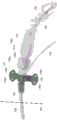
图1示出了根据本公开各方面的示例性系统100,其包括血泵和重定位鞘组件110,以及导引器鞘组件150。FIG. 1 illustrates an
示例性血泵和重定位鞘组件110包括位于其近端的手柄138。手柄138被联接到导管122的近端。另外,在图1的示例中,净化流体端口140被连接到手柄138,以便将净化流体(例如,葡萄糖或葡萄糖与肝素的溶液)提供到导管122内的净化管腔(未示出)。导管122的净化管腔被配置为以将净化流体输送到马达外壳120。The exemplary blood pump and
在手柄138和固定设备132之间,导管122被封闭在保护套筒136内。保护套筒136被配置为在导管122在向远侧方向上推进以插入患者脉管系统中时防止污染导管122。保护套筒136可以由任何合适的材料组成,并且可以以任何合适的方式固定在其近端和远端。保护套筒136的远端被联接到固定设备132。在这方面,对于本技术的按钮致动的固定设备,保护套筒136可以被联接到按钮的近侧(例如,如图3和图4所示),或者可以被联接到按钮的远侧,使得按钮被维持在保护套筒136内并且避免按钮边缘周围的污染(例如,如图8和图9所示)。在图1的示例中,固定设备在其远端被联接到止血阀131,止血阀131又附接到蝶形件130。止血阀131可以与蝶形件130集成,或者可以可移除地联接到其上。另外,如上文和下文所讨论的,止血阀131和固定设备132可以合并到单个单元中。蝶形件130在其远端被联接到重定位鞘126的近端128。重定位鞘126的远端用附图标记124表示。重定位鞘126被配置有大小允许至少导管122通过的管腔,但除此之外可以有任何合适的长度和结构。Between the
导管122的远端被连接到马达外壳120的近端。在本技术的一些方面,马达外壳120可以包括马达和叶轮。在本技术的另一些方面,马达可以在患者体外,在这种情况下导管122可以封装柔性驱动轴/电缆,并且马达外壳120可以封装连接到该驱动轴/电缆的叶轮。应当理解,本技术的固定设备可以与操作员希望限制移动的任何心内血泵或其它静脉内医疗设备一起使用。The distal end of
在图1的示例中,马达外壳120的远端被连接到血液流出笼118。血液流出笼118的远端被连接到插管116,插管116又在其远端被联接到血液流入笼114。当泵正在运行时,血液将在向近侧方向上从血液流入笼114通过插管116被泵送到血液流出笼118。然而,在本技术的一些方面,泵可以替代地被配置为在向远侧方向上泵送血液(例如,对于泵用于右心支持的应用),在这种情况下,元件118将作为血液流入笼操作,而元件114将作为血液流出笼操作。最后,在本技术的一些方面,血液流入笼114的远端可以包括无损伤延伸部,例如图1的示例中所示的尾纤延伸部112。In the example of FIG. 1 , the distal end of the
通常,血泵最初将经由诸如示例性导引器鞘组件150的导引器鞘插入患者的脉管系统中。在这方面,导引器鞘组件150包括导引器鞘主体152、毂154和冲洗管线156。导引器鞘主体152可以是任何合适类型的鞘。例如,在本技术的一些方面,导引器鞘主体152可以是可扯开的鞘,其被配置为沿其长度撕开或剥离并在重定位鞘126已插入患者脉管系统后丢弃。然而,在本技术的另一些方面,导引器鞘主体152可以是可扩张的鞘,其被配置为拉伸以允许血泵的最大部分通过,并然后收缩,在这种情况下,导引器鞘甚至可以在泵已插入患者的脉管系统后仍然保持在原位。在图1的示例中,毂154被示为带有可选的蝶形件154a,蝶形件154a可用于将导引器鞘组件150固定至患者(例如,使用粘合剂或缝合线)。毂154还可以包括止血阀(未示出)。另外,冲洗管线156被示为带有可选的旋塞阀组件156a,在图1的示例中,旋塞阀组件156a包括两个端口。Typically, the blood pump will initially be inserted into the patient's vasculature via an introducer sheath such as exemplary
一旦血泵已被插入患者的脉管系统中,操作员就可以将血泵推进至其在身体中的期望位置(例如,左心或右心)。随着导管122进一步推进到患者脉管系统中,重定位鞘126的远端124可以插入导引器鞘组件150中。在这方面,导引器鞘主体152将充当用于重定位鞘126进入患者的脉管系统的管道。在另一些情况下,当导管122被推进到患者的脉管系统中时,重定位鞘126可以保留在导引器150外面。如前所述,在导引器鞘组件150是扯开式设计的情况下,在重定位鞘126已插入到在患者的脉管系统中后,导引器鞘组件150可以通过折断毂154并沿其长度扯开导引器鞘主体152来移除。然而,在导引器鞘组件150是可扩张设计的情况下,它可以保留在体内,围住一些或全部重定位鞘126,或者在重定位鞘126保留在体外的情况下,围住导管122。Once the blood pump has been inserted into the patient's vasculature, the operator can advance the blood pump to its desired location in the body (eg, left or right heart). As
一旦重定位鞘126已完全插入,操作员就可以使用蝶形件130在插入部位处或附近将其固定至患者。在这方面,可以将蝶形件130粘附至患者(例如,使用粘合剂或缝合线)以便相对于患者固定重定位鞘126和固定设备132。可替代地,如果重定位鞘126保留在体外,则可以使用蝶形件154a将导引器鞘150粘附至患者,并且类似于132的固定设备可以位于导引器毂154处,并且类似地允许相对于患者固定泵。此后,一旦血泵已经被推进到患者体内的期望位置,操作员就可以使用固定设备132来限制血泵在患者体内的进一步移动。在这方面,固定设备132可以是适合于可选地允许和限制导管122从中移动的任何设备。尽管在图1的示例性系统100中描绘的特定固定设备132是传统的Tuohy-Borst型设备,但是参照图3-9描绘和描述的任何改进的固定设备都可以用来代替固定设备132。另外,尽管图1-8的固定设备被示为是联接到重定位鞘组件的止血阀的模块化单元,但本技术的固定设备可以可替代地提供为:(1)联接到导引器鞘组件的止血阀的模块化单元;(2)包含止血阀并联接到重定位鞘组件或导引器鞘组件的毂的模块化单元;或(3)作为重定位鞘组件或导引器鞘组件的组成部分。Once
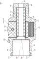
图2示出了图1的血泵和重定位鞘组件的放大图。就此而言,图1和图2之间共享的所有附图标记旨在指示相同的特征,并且除非有必要解释图2中所示的附加特征,否则将不再提及。图2再现了血泵和重定位鞘组件110的一部分,该组件被定向成其远端朝向左侧,就好像重定位鞘126已经从右到左穿过患者的皮肤表面(由虚线160指示)。以这种方式定向,重定位鞘126的近端128将保留在患者体外,并且蝶形件130可以使用穿过缝线孔眼130a、130b、130c和130d的缝线固定到患者的皮肤。FIG. 2 shows an enlarged view of the blood pump and repositioning sheath assembly of FIG. 1 . In this regard, all reference numerals shared between Figures 1 and 2 are intended to indicate the same features and will not be mentioned again unless it is necessary to explain additional features shown in Figure 2 . FIG. 2 reproduces a portion of the blood pump and
图2的放大图示出了止血阀131和固定设备132之间的卡口连接。在这方面,固定设备132的远端被配置为使得它可以通过将两个部分推到一起并将它们相对于彼此转动而联接到止血阀131的近端。在图2的示例中,固定设备132的远侧部分具有带一个或多个狭槽的圆柱形套环,而止血阀131的近侧部分具有带一个或多个栓钉131a的圆柱形突起。当固定设备132的圆柱形套环在止血阀131的圆柱形突起上推进时,每个栓钉131a将在入口点132a处进入固定设备132中的狭槽中的一个。然后,通过相对于止血阀131旋转固定设备132,每个栓钉131a将朝向狭槽的端点132b移动,从而防止固定设备132被拉离止血阀131(无需先沿相反的方向旋转这两个部件)。另外,固定设备132的圆柱形套环和止血阀131之间的内部接口可以包括可变形的密封件或垫圈(例如,橡胶垫片),以在这两部分之间提供密封并提供背压,该背压倾向于防止栓钉131a容易地在固定设备132的狭槽内移动。此外,可以在固定设备132中的每个狭槽的端点132b处提供棘爪,使得栓钉131a将倾向于保持在锁定状态。The enlarged view of FIG. 2 shows the bayonet connection between the
如前所述,在图1和图2的示例中,固定设备132是传统的Tuohy-Borst设备,其中筒体132c被旋转以改变施加在固定设备132内的任何物体(例如,导管122)上的阻力的量。同样,如将下文更详细地讨论的,参照图3-9描绘和描述的任何改进的固定设备都可以替换为图1和图2所示的系统。此外,同样如上所述,在所有情况下,本技术的固定设备可以与重定位鞘结合使用(例如,作为重定位鞘的毂的一部分或连接到重定位鞘的毂)或者与导引器鞘结合使用(例如,作为导引器鞘的毂的一部分或连接到导引器鞘的毂)。As previously mentioned, in the example of FIGS. 1 and 2 , the
图3示出了根据本公开各方面的使用示例性按钮致动的固定设备的血泵和重定位鞘组件的放大图。像图2一样,图3的示例示出了血泵和重定位鞘组件的一部分,该组件被定向成其远端朝向左侧。图3及图1和图2之间的所有共享的数字代表相同的特征。因此,导管122、重定位鞘126(其仅近端128被标识)、蝶形件130、止血阀131和保护套筒136都如前所述。然而,不同于图2,图3的示例没有示出传统的Tuohy-Borst型固定设备,而是采用按钮致动的固定设备200。3 illustrates an enlarged view of a blood pump and repositioning sheath assembly using an exemplary button-actuated fixation device according to aspects of the present disclosure. Like FIG. 2, the example of FIG. 3 shows a portion of the blood pump and repositioning sheath assembly oriented with its distal end toward the left. Figure 3 and all shared numbers between Figures 1 and 2 represent the same features. Thus,
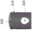
固定设备200包括容纳按钮202的主体201。固定设备200的主体201包括两个孔眼204(图3中只有一个可见),每个孔眼都被配置为接合栓钉131a(未示出,但如上所述)以实现止血阀131和固定设备200之间的卡扣配合。如下文将参照图6进一步描述的那样,按钮202是弹簧加载的,从而它将夹在内部柔性套筒210(图3中不可见)上,并因此无论何时按钮202没有被主动压下时提供阻力至任何被插入穿过该柔性套筒的管腔的物体。为了避免在使用前(例如,当固定设备200被搁置在库存中时)在柔性套筒210上施加持续压力(这可能会导致柔性套筒产生一定量的持久变形)并且/或者允许泵在手术开始时更容易地移动,示例性固定设备200包括固持销206。如下文将参照图6进一步描述的,固持销206可以插入穿过主体201和按钮202中的孔以将按钮202保持在压下状态,使得柔性套筒210不会受到按钮202的压力。The
图4示出了图3的示例性按钮致动的固定设备的三维模型的立体图,并且图5示出了其线图。因为图4和图5单独示出固定设备200,所以可以更详细地看到主体201的远侧管腔228。特别地,提供对应于孔眼204的直径的两个狭槽204a。狭槽204a在向近侧方向上略微倾斜,使得当止血阀131的圆柱形突起推进到主体201的远端处的圆柱形套环中时,栓钉131a和狭槽204a之间的阻力将逐渐增加,直到两个栓钉131a“卡扣”到与两个孔眼204接合为止。狭槽204a的斜坡也可以在图7的横截面视图中看到。Figure 4 shows a perspective view of a three-dimensional model of the exemplary button-actuated fixation device of Figure 3, and Figure 5 shows a line drawing thereof. Since FIGS. 4 and 5
图4的三维模型还更清楚地示出主体201具有被配置为与保护套筒136联接的近侧套环208。近侧套环208和保护套筒136之间的联接可以通过任何合适的方式实现。例如,保护套筒136可以结合到套环208或使用粘合剂等粘附到其上。此外,保护套筒136可以使用任何合适的机械联接可移除地联接到套环208,所述机械联接诸如安装在套环208上的环,该环可以是拧紧或以其它方式移动到与主体201的另一表面接合,以便捕获保护套筒136的端部。The three-dimensional model of FIG. 4 also more clearly shows that the
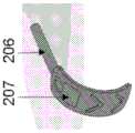
图4和图5的三维模型和线图还示出了与图3中所示的稍有不同的固持销206。如图3所示,固持销206是可选的,并且可以采用任何合适形状或构造的固持销。The three-dimensional models and line drawings of FIGS. 4 and 5 also show a slightly
图6示出了图3的示例性按钮致动的固定设备的分解图。在这个分解图中,可以看到按钮202有两个孔。孔216被配置为允许固持销206通过按钮202的一部分。主体201具有两个相同或相似大小的孔218。因此,孔216和218允许固持销206穿过主体201和按钮202,因此将按钮202保持在按下状态。FIG. 6 shows an exploded view of the exemplary button-actuated fixation device of FIG. 3 . In this exploded view, it can be seen that
按钮202还具有第二孔220,第二孔220的大小设计成允许柔性套筒210通过。柔性套筒210可以由任何合适的材料组成,例如硅树脂等。柔性套筒210具有管腔212,管腔212的大小设计成允许任何设备旨在穿过固定设备200通过。因此,如果固定设备200用于血泵和重定位鞘组件中,例如图1-3中所示的那些,则管腔212的大小可以设计成当柔性套筒210处于松弛、未压缩状态时允许导管122通过。可以部分地选择用于柔性套筒210的尺寸和材料,以在管腔212与旨在穿过固定设备200的任何医疗设备之间提供期望量的摩擦,并且/或者为医疗设备提供足够的缓冲以防止在未按下固定设备200的按钮202时损坏医疗设备。例如,如果固定设备200用于血泵和重定位鞘组件中,例如图1-3中所示的那些,则柔性套筒210可以通过选择特定材料、壁厚等来配置以向导管122提供足够的摩擦从而防止导管122在按钮202未被按下时移动,同时还避免卷曲导管122和/或不利地影响可以穿过导管122的任何电线、净化管腔、柔性驱动轴等。
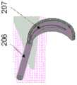
用于固持销的不同配置在图10A-10D中图示。如图10A、图10B和图10C所示,固持销206具有弯曲的手柄207,手柄207使用户能够简单地通过将他们的手指插入手柄207后面并将销206从按钮202中的孔216中及从主体201中的孔218中移除来移除销206。如图10D所示,按钮202中的第二孔220朝向接收在主体201中的按钮202的下部逐渐变细。因此,第二孔220在第二孔220的顶部具有较大的直径而在第二孔220的下部具有较小的直径,按钮202的“顶部”和“下部”与按钮202被接收到其中的主体201的“顶部”相关。如上面详细描述的,当按钮202处于压缩(压下)状态时,这种设计便于按钮在导管上的动作,使得导管被牢固地保持,而不是卷曲。Different configurations for retaining pins are illustrated in Figures 10A-10D. As shown in Figures 10A, 10B, and 10C, the retaining
正如下面将参照图7进一步解释的那样,主体201包括中间管腔226(在图6中不可见),中间管腔226的大小设计成固持柔性套筒210。此外,主体201包括凹槽213(在图6中也不可见),凹槽213被配置为将弹簧214固持在按钮202下方。尽管弹簧214被描绘为螺旋弹簧,但是可以用任何合适的弹簧构件代替,例如片簧、弹性体元件、活动铰链等。当固定设备200被组装成使得弹簧214保持在凹槽213内并且柔性套筒210通过按钮202的孔220并通过主体201的中间管腔226被旋入时,弹簧214将处于压缩,并从而提供倾向于将按钮202向上推出按钮腔219的力。该力继而将导致孔220提供倾向于向上推动柔性套筒210的力,从而将其卡在中间管腔226的顶部。通过选择具有足够强度的弹簧214和足够柔韧的柔性套筒210,按钮202上的这个向上的力将导致柔性套筒210变形,并导致管腔212夹住任何可能穿过其插入的物体(例如,导管122),从而阻止物体移动通过管腔212。相反,通过按下按钮202,弹簧214将被进一步压缩,并且柔性套筒210上的力将减小或移除,从而允许柔性套筒210返回至松弛状态,在该松弛状态中,管腔212将允许穿过其插入的任何物体(例如,导管122)通过。参照图10A-10D在本文中描述的备选固持销设计和备选第二孔设计中的任一者或两者可以与本文描述的按钮致动的固定设备的其它实施例结合。As will be explained further below with reference to FIG. 7 ,
图7示出了图3的示例性按钮致动的固定设备的横截面视图。与图3-6共同的所有附图标记标识与上述相同的特征。从图7的横截面视图可以看出,主体201具有与管腔212大小基本相似的近侧管腔222、与柔性套筒210的松弛外径基本相似大小的中间管腔226以及与止血阀131的圆柱形突起基本相似大小的远侧管腔226。图7示出了固定设备200,其中固持销206已经被插入穿过孔216和218,并且因此示出了处于按下状态的按钮202。如上所述,一旦固持销206被移除,弹簧214将开始向上压在按钮202的底表面上,这又将导致按钮202的孔220将柔性套筒210压靠在中间管腔226的顶部,从而导致压缩柔性套筒210及其管腔212。FIG. 7 illustrates a cross-sectional view of the exemplary button-actuated fixation device of FIG. 3 . All reference numbers common to Figures 3-6 identify the same features as described above. As can be seen from the cross-sectional view of FIG. The cylindrical protrusions are substantially similar in size to the
图8示出了根据本公开各方面的使用示例性按钮致动的固定设备的血泵和重定位鞘组件的放大图。在这方面,像图2和图3一样,图8示出了血泵和重定位鞘组件的一部分,该组件被定向成其远端朝向左侧。图8及图1-3之间的所有共享的数字代表相同的特征。因此,导管122、重定位鞘126(及其近端128)、蝶形件130、止血阀131和保护套筒136都如前所述。像图3-7一样,图8还示出了固定设备300,其包括按钮302,并且被配置为以与上面参照图3-7所描述的相同方式限制通过它插入的物体的移动。然而,不同于图3-7,图8的固定设备300被配置为使用类似于上面参照图2所描述的卡口连接来联接到止血阀。8 illustrates an enlarged view of a blood pump and repositioning sheath assembly using an exemplary button-actuated fixation device in accordance with aspects of the present disclosure. In this regard, like FIGS. 2 and 3 , FIG. 8 shows a portion of the blood pump and repositioning sheath assembly oriented with its distal end toward the left. All shared numbers between Figure 8 and Figures 1-3 represent the same features. Thus,
在这方面,在图8中,固定设备300的主体301的远端被配置为使得它可以通过将两个部分推到一起并相对于彼此转动而联接到止血阀131的近端。与图1和图2的示例一样,固定设备300的远侧部分具有带一个或多个狭槽的圆柱形套环,而止血阀131的近侧部分具有带一个或多个栓钉131a的圆柱形突起。当固定设备300的圆柱形套环在止血阀131的圆柱形突起上推进时,每个栓钉131a将在入口点304a处进入固定设备300中的狭槽中的一个。然后,通过相对于止血阀131旋转固定设备300,每个栓钉131a将朝向狭槽的端点304b移动,从而防止固定设备300被拉离止血阀131(无需先沿相反的方向旋转这两个部件)。另外,固定设备300的圆柱形套环和止血阀131之间的内部接口可以包括可变形的密封件或垫圈(例如,橡胶垫片),以在这两部分之间提供密封并提供背压,该背压倾向于防止栓钉131a容易地在固定设备300的狭槽内移动。此外,可以在固定设备300的每个狭槽的端点304b处设置棘爪,使得栓钉131a将倾向于保持在锁定状态。In this regard, in FIG. 8 , the distal end of the
另外,在图8的示例中,保护套筒136在按钮302上延伸,以防止这种可能性,即,流体、微生物等围绕按钮302的边缘进入固定设备300,并因此在导管122在固定设备300内经过的情况下污染导管122。固定设备300具有固持环306,固持环306被配置为将保护套筒136的端部卡在主体301的相对表面上。如上所述,可以以任何合适的方式实现这种卡住布置。同样,在本技术的一些方面,保护套筒136可以直接结合到环306和/或主体301,或者使用粘合剂粘附到其上。Additionally, in the example of FIG. 8 ,
图9示出了根据本公开各方面的使用示例性按钮致动的固定设备的血泵和重定位鞘组件的放大图。这里也是同样,图8的示例示出了血泵和重定位鞘组件的一部分,该组件被定向成其远端朝向左侧。图9及图1-3之间的所有共享的数字代表相同的特征。因此,导管122、重定位鞘126(及其远端124和近端128)、蝶形件130和保护套筒136都如前所述。图9还示出了固定设备400,其包括按钮402,并且被配置为以与上面参照图3-7所描述的相同方式限制通过它插入的物体的移动。然而,不同于图1-8,图9的固定设备400包括其内的止血阀(未示出)。因此,图9所示的血泵和重定位鞘组件的该部分不需要单独的止血阀131,并且因此固定设备400的主体401不需要任何特征来实现其与止血阀131之间的联接(例如,卡口连接、卡扣连接等)。就此而言,在本技术的一些方面,固定设备400可以是使用任何合适的联接布置直接附接到蝶形件130的模块化单元。然而,在本技术的另一些方面,固定设备400可以与重定位鞘组件的毂集成,并且因此重定位鞘126、蝶形件130和固定设备400可以是单个重定位鞘组件的一部分。同样,如上所述,固定设备400也可以被配置为与导引器鞘组件(例如,导引器鞘组件150)一起工作或者成为导引器鞘组件的组成部分。9 illustrates an enlarged view of a blood pump and repositioning sheath assembly using an exemplary button-actuated fixation device in accordance with aspects of the present disclosure. Here too, the example of FIG. 8 shows a portion of a blood pump and repositioning sheath assembly oriented with its distal end toward the left. All shared numbers between Figure 9 and Figures 1-3 represent the same features. Accordingly,
从前述内容并参考各种附图,本领域技术人员将理解,在不脱离本公开的范围的情况下,还可以对本公开进行某些修改。虽然附图中已示出了本公开的几个方面,但并不意在将本公开限制于此,因为本公开意在在本领域允许的范围内具有宽广的范围并且以同样方式阅读说明书。因此,以上描述不应被解释为限制,而仅仅是本技术的特定方面的范例。From the foregoing, and with reference to the various drawings, it will be appreciated by those skilled in the art that certain modifications may be made to the present disclosure without departing from the scope of the present disclosure. While several aspects of the disclosure have been shown in the drawings, it is not intended to limit the disclosure thereto, as the disclosure is intended to have as broad a scope as the art allows and the specification should be read in such a manner. Accordingly, the above description should not be construed as limiting, but merely as exemplifications of certain aspects of the technology.
Claims (20)
Applications Claiming Priority (3)
| Application Number | Priority Date | Filing Date | Title |
|---|---|---|---|
| US202063058003P | 2020-07-29 | 2020-07-29 | |
| US63/058,003 | 2020-07-29 | ||
| PCT/US2021/043491WO2022026569A1 (en) | 2020-07-29 | 2021-07-28 | Securement devices for intracardiac blood pump systems |
Publications (1)
| Publication Number | Publication Date |
|---|---|
| CN116075334Atrue CN116075334A (en) | 2023-05-05 |
Family
ID=77499912
Family Applications (1)
| Application Number | Title | Priority Date | Filing Date |
|---|---|---|---|
| CN202180058275.9APendingCN116075334A (en) | 2020-07-29 | 2021-07-28 | Stationary equipment for intracardiac blood pump systems |
Country Status (11)
| Country | Link |
|---|---|
| US (1) | US20220032037A1 (en) |
| EP (1) | EP4188511A1 (en) |
| JP (1) | JP2023536095A (en) |
| KR (1) | KR20230042478A (en) |
| CN (1) | CN116075334A (en) |
| AU (1) | AU2021315988A1 (en) |
| CA (1) | CA3185417A1 (en) |
| DE (1) | DE112021004041T5 (en) |
| IL (1) | IL300050A (en) |
| TW (1) | TW202216230A (en) |
| WO (1) | WO2022026569A1 (en) |
Families Citing this family (1)
| Publication number | Priority date | Publication date | Assignee | Title |
|---|---|---|---|---|
| WO2025160488A1 (en) | 2024-01-26 | 2025-07-31 | Abiomed, Inc. | Steerable catheter assemblies |
Citations (8)
| Publication number | Priority date | Publication date | Assignee | Title |
|---|---|---|---|---|
| US3986508A (en)* | 1973-08-22 | 1976-10-19 | Abcor, Inc. | Sterilizable, medical connector for blood processing |
| US4253684A (en)* | 1979-05-14 | 1981-03-03 | Monsanto Company | Quick connect coupler with air shield |
| US4327709A (en)* | 1978-03-06 | 1982-05-04 | Datascope Corp. | Apparatus and method for the percutaneous introduction of intra-aortic balloons into the human body |
| DE4213691A1 (en)* | 1992-04-25 | 1993-11-04 | Aesculap Ag | Surgical trocar with sleeve - has slider within sleeve moved by spring between open and closed positions and locked in open position by bolt |
| US7022100B1 (en)* | 1999-09-03 | 2006-04-04 | A-Med Systems, Inc. | Guidable intravascular blood pump and related methods |
| US20070017583A1 (en)* | 2005-07-06 | 2007-01-25 | Fangrow Thomas F Jr | Medical connector with closeable male luer |
| US20100268163A1 (en)* | 2005-06-30 | 2010-10-21 | Abbott Laboratories | Modular introducer and exchange sheath |
| US20130204206A1 (en)* | 2012-01-09 | 2013-08-08 | BiO2 Medical, Inc. | Connector hub apparatus for catheter and methods of use |
Family Cites Families (6)
| Publication number | Priority date | Publication date | Assignee | Title |
|---|---|---|---|---|
| US5921968A (en)* | 1997-11-25 | 1999-07-13 | Merit Medical Systems, Inc. | Valve apparatus with adjustable quick-release mechanism |
| DE60211942T2 (en)* | 2001-12-04 | 2007-01-25 | Cook Inc., Bloomington | ACCESS VALVE |
| JP4472310B2 (en)* | 2003-11-12 | 2010-06-02 | テルモ株式会社 | Medical connector |
| JP2017093471A (en)* | 2014-03-27 | 2017-06-01 | テルモ株式会社 | Medical aid |
| EP3506965B1 (en)* | 2016-08-30 | 2025-02-19 | Sanofi-Aventis Deutschland GmbH | Injection device |
| WO2019050765A1 (en)* | 2017-09-06 | 2019-03-14 | Inari Medical, Inc. | Hemostasis valves and methods of use |
- 2021
- 2021-07-28CNCN202180058275.9Apatent/CN116075334A/enactivePending
- 2021-07-28KRKR1020237004843Apatent/KR20230042478A/enactivePending
- 2021-07-28CACA3185417Apatent/CA3185417A1/enactivePending
- 2021-07-28EPEP21759450.6Apatent/EP4188511A1/enactivePending
- 2021-07-28ILIL300050Apatent/IL300050A/enunknown
- 2021-07-28USUS17/387,359patent/US20220032037A1/enactivePending
- 2021-07-28TWTW110127715Apatent/TW202216230A/enunknown
- 2021-07-28DEDE112021004041.3Tpatent/DE112021004041T5/enactivePending
- 2021-07-28WOPCT/US2021/043491patent/WO2022026569A1/ennot_activeCeased
- 2021-07-28JPJP2023505823Apatent/JP2023536095A/enactivePending
- 2021-07-28AUAU2021315988Apatent/AU2021315988A1/enactivePending
Patent Citations (8)
| Publication number | Priority date | Publication date | Assignee | Title |
|---|---|---|---|---|
| US3986508A (en)* | 1973-08-22 | 1976-10-19 | Abcor, Inc. | Sterilizable, medical connector for blood processing |
| US4327709A (en)* | 1978-03-06 | 1982-05-04 | Datascope Corp. | Apparatus and method for the percutaneous introduction of intra-aortic balloons into the human body |
| US4253684A (en)* | 1979-05-14 | 1981-03-03 | Monsanto Company | Quick connect coupler with air shield |
| DE4213691A1 (en)* | 1992-04-25 | 1993-11-04 | Aesculap Ag | Surgical trocar with sleeve - has slider within sleeve moved by spring between open and closed positions and locked in open position by bolt |
| US7022100B1 (en)* | 1999-09-03 | 2006-04-04 | A-Med Systems, Inc. | Guidable intravascular blood pump and related methods |
| US20100268163A1 (en)* | 2005-06-30 | 2010-10-21 | Abbott Laboratories | Modular introducer and exchange sheath |
| US20070017583A1 (en)* | 2005-07-06 | 2007-01-25 | Fangrow Thomas F Jr | Medical connector with closeable male luer |
| US20130204206A1 (en)* | 2012-01-09 | 2013-08-08 | BiO2 Medical, Inc. | Connector hub apparatus for catheter and methods of use |
Also Published As
| Publication number | Publication date |
|---|---|
| AU2021315988A1 (en) | 2023-03-30 |
| US20220032037A1 (en) | 2022-02-03 |
| TW202216230A (en) | 2022-05-01 |
| WO2022026569A1 (en) | 2022-02-03 |
| DE112021004041T5 (en) | 2023-08-03 |
| IL300050A (en) | 2023-03-01 |
| JP2023536095A (en) | 2023-08-23 |
| CA3185417A1 (en) | 2022-02-03 |
| KR20230042478A (en) | 2023-03-28 |
| EP4188511A1 (en) | 2023-06-07 |
Similar Documents
| Publication | Publication Date | Title |
|---|---|---|
| JP6638975B2 (en) | Transdermal systems, devices, and methods | |
| JP5118148B2 (en) | Separate hemostatic hub | |
| JP2025120471A (en) | Vascular Access | |
| JP2021112640A (en) | Vascular access device | |
| US8540616B2 (en) | Ventricular assist device and related methods | |
| IL302716A (en) | Systems and methods for minimizing leaks during pump insertion | |
| KR20240035925A (en) | Blood pump with flow cannula | |
| US20100161040A1 (en) | Cardiovascular valve and valve housing apparatuses and systems | |
| US11944767B2 (en) | Wire lock assembly | |
| JP7691988B2 (en) | Dilator sheath assembly having interlocking arrangement - Patents.com | |
| EP2543342A1 (en) | Artificial blood vessel | |
| JP2012075890A (en) | Tunneler device and method of use | |
| CN116075334A (en) | Stationary equipment for intracardiac blood pump systems | |
| US20180303988A1 (en) | Aortic connectors and methods of use | |
| US11383072B2 (en) | Methods and systems for selection and use of connectors between conduits | |
| US20250281723A1 (en) | Percutaneous Catheter Fixation Ladder Lock | |
| US20230355923A1 (en) | Introducer sheath with peel away perfusion aperture | |
| US20250312136A1 (en) | Graft-Integrated Intravascular Catheter Fixation | |
| US20250312570A1 (en) | Staple-Actuated Catheter Fixation Device | |
| KR102869674B1 (en) | Systems and methods for minimizing leaks during insertion of pumps |
Legal Events
| Date | Code | Title | Description |
|---|---|---|---|
| PB01 | Publication | ||
| PB01 | Publication | ||
| SE01 | Entry into force of request for substantive examination | ||
| SE01 | Entry into force of request for substantive examination |