CN116073697A - Four-foot multi-freedom-degree ultrasonic motor composited by longitudinal bending modes and excitation method thereof - Google Patents
Four-foot multi-freedom-degree ultrasonic motor composited by longitudinal bending modes and excitation method thereofDownload PDFInfo
- Publication number
- CN116073697A CN116073697ACN202211030949.7ACN202211030949ACN116073697ACN 116073697 ACN116073697 ACN 116073697ACN 202211030949 ACN202211030949 ACN 202211030949ACN 116073697 ACN116073697 ACN 116073697A
- Authority
- CN
- China
- Prior art keywords
- piezoelectric ceramic
- vibration
- axis
- excitation signal
- spherical
- Prior art date
- Legal status (The legal status is an assumption and is not a legal conclusion. Google has not performed a legal analysis and makes no representation as to the accuracy of the status listed.)
- Pending
Links
Images


Classifications
- H—ELECTRICITY
- H02—GENERATION; CONVERSION OR DISTRIBUTION OF ELECTRIC POWER
- H02N—ELECTRIC MACHINES NOT OTHERWISE PROVIDED FOR
- H02N2/00—Electric machines in general using piezoelectric effect, electrostriction or magnetostriction
- H02N2/10—Electric machines in general using piezoelectric effect, electrostriction or magnetostriction producing rotary motion, e.g. rotary motors
- H02N2/108—Electric machines in general using piezoelectric effect, electrostriction or magnetostriction producing rotary motion, e.g. rotary motors around multiple axes of rotation, e.g. spherical rotor motors
- H—ELECTRICITY
- H02—GENERATION; CONVERSION OR DISTRIBUTION OF ELECTRIC POWER
- H02N—ELECTRIC MACHINES NOT OTHERWISE PROVIDED FOR
- H02N2/00—Electric machines in general using piezoelectric effect, electrostriction or magnetostriction
- H02N2/10—Electric machines in general using piezoelectric effect, electrostriction or magnetostriction producing rotary motion, e.g. rotary motors
- H02N2/12—Constructional details
- H—ELECTRICITY
- H02—GENERATION; CONVERSION OR DISTRIBUTION OF ELECTRIC POWER
- H02N—ELECTRIC MACHINES NOT OTHERWISE PROVIDED FOR
- H02N2/00—Electric machines in general using piezoelectric effect, electrostriction or magnetostriction
- H02N2/10—Electric machines in general using piezoelectric effect, electrostriction or magnetostriction producing rotary motion, e.g. rotary motors
- H02N2/14—Drive circuits; Control arrangements or methods
- H02N2/145—Large signal circuits, e.g. final stages
Landscapes
- General Electrical Machinery Utilizing Piezoelectricity, Electrostriction Or Magnetostriction (AREA)
Abstract
Translated fromChinese
Description
Translated fromChinese技术领域technical field
本发明涉及超声电机技术领域,尤其涉及一种纵弯模态复合的四足多自由度超声电机及其激励方法。The invention relates to the technical field of ultrasonic motors, in particular to a quadruped multi-degree-of-freedom ultrasonic motor with composite longitudinal-bending modes and an excitation method thereof.
背景技术Background technique
在机器人技术、光学仪器、医疗器械等精密驱动领域中,对作动器的品质有了更多的限制和要求,要求作动器能够实现多自由度运动、定位精度高以及易于小型化,传统的多自由度是使用多台单自由度旋转电机串联以及复杂的传动机构来实现多自由度会导致体积庞大、结构复杂、误差失控和难以小型化。In the field of precision drives such as robotics, optical instruments, and medical equipment, there are more restrictions and requirements on the quality of actuators, which require actuators to be able to achieve multi-degree-of-freedom movements, high positioning accuracy, and easy miniaturization. The multi-degree-of-freedom is the use of multiple single-degree-of-freedom rotating motors in series and complex transmission mechanisms to achieve multi-degree-of-freedom, which will lead to bulky, complex structures, out-of-control errors and difficulty in miniaturization.
发明内容Contents of the invention
本发明所要解决的技术问题是针对背景技术中所涉及到的缺陷,提供一种纵弯模态复合的四足多自由度超声电机及其激励方法。The technical problem to be solved by the present invention is to provide a quadruped multi-degree-of-freedom ultrasonic motor with composite longitudinal and bending modes and its excitation method for the defects involved in the background technology.
本发明为解决上述技术问题采用以下技术方案:The present invention adopts the following technical solutions for solving the problems of the technologies described above:
一种纵弯模态复合的四足多自由度超声电机,包含压电振子和球形转子;A quadruped multi-degree-of-freedom ultrasonic motor combined with longitudinal and bending modes, including a piezoelectric vibrator and a spherical rotor;
所述压电振子包含第一至第四振动梁、以及第一至第四横梁;The piezoelectric vibrator includes first to fourth vibration beams, and first to fourth beams;
所述第一至第四振动梁结构相同,均包含上梁、夹持件、下梁、第一至第四压电陶片、以及预紧螺栓;The first to fourth vibrating beams have the same structure, and all include an upper beam, a clamping piece, a lower beam, first to fourth piezoelectric ceramic sheets, and pre-tightening bolts;
所述上梁、下梁为形状相同的正四棱柱,上梁的上端沿其轴线设有和所述预紧螺栓相匹配的沉头通孔,下梁上端的中心设有和所述预紧螺栓相匹配的螺纹盲孔;The upper beam and the lower beam are square prisms with the same shape, the upper end of the upper beam is provided with a countersunk through hole matching the pre-tightening bolt along its axis, and the center of the upper end of the lower beam is provided with a countersunk hole matching the pre-tightening bolt. Matching threaded blind holes;
所述夹持件结构包含夹持部、柔性铰链和限位部,所述夹持部为横截面和上梁横截面形状相同的正四棱柱;所述限位部为上开下口的空心圆柱体;所述限位部的侧壁通过所述柔性铰链和所述夹持部的一个侧壁的中心垂直固连,使得限位部的轴线平行于夹持部的轴线,且所述夹持部沿其轴线设有供所述预紧螺栓穿过的通孔;The clamp structure includes a clamping part, a flexible hinge and a limiting part. The clamping part is a regular quadrangular prism with the same cross-section as that of the upper beam; the limiting part is a hollow cylinder with an upper opening and a lower opening Body; the side wall of the limiting part is vertically fixed to the center of a side wall of the clamping part through the flexible hinge, so that the axis of the limiting part is parallel to the axis of the clamping part, and the clamping The part is provided with a through hole along its axis for the pre-tightening bolt to pass through;
所述第一至四压电陶片的形状和所述上梁横截面的形状相同,中心均设有供所述预紧螺栓穿过的通孔,且第一、第四压电陶瓷片采用二分区压电陶瓷片,第二、第三压电陶瓷片采用单分区压电陶瓷片;The shapes of the first to four piezoelectric ceramic sheets are the same as the shape of the cross-section of the upper beam, and there are through holes in the center for the pre-tightening bolts to pass through, and the first and fourth piezoelectric ceramic sheets are made of Two-part piezoelectric ceramic sheets, the second and third piezoelectric ceramic sheets use single-partition piezoelectric ceramic sheets;
所述预紧螺栓从上梁的沉头通孔穿入,依次穿过第一压电陶瓷片、第二压电陶瓷片、夹持部、第三压电陶瓷片、第四压电陶瓷片上的通孔后和所述下梁的螺纹盲孔螺纹相连,将第一压电陶瓷片、第二压电陶瓷片、夹持部、第三压电陶瓷片、第四压电陶瓷片夹紧在上梁、下梁之间,第一、第四压电陶瓷片的分界线相互垂直;所述第二、第三压电陶瓷片的极化方向均沿厚度方向朝下;所述第一、第四压电陶瓷片均沿厚度方向极化,且两个分区的极化方向相反;The pre-tightening bolt penetrates through the countersunk through hole of the upper beam, and passes through the first piezoelectric ceramic sheet, the second piezoelectric ceramic sheet, the clamping part, the third piezoelectric ceramic sheet, and the fourth piezoelectric ceramic sheet in sequence. After the through hole is connected with the threaded blind hole of the lower beam, the first piezoelectric ceramic sheet, the second piezoelectric ceramic sheet, the clamping part, the third piezoelectric ceramic sheet, and the fourth piezoelectric ceramic sheet are clamped Between the upper beam and the lower beam, the boundary lines of the first and fourth piezoelectric ceramic sheets are perpendicular to each other; the polarization directions of the second and third piezoelectric ceramic sheets are both downward along the thickness direction; the first , the fourth piezoelectric ceramic sheet is polarized along the thickness direction, and the polarization directions of the two partitions are opposite;
所述第一、第二振动梁的上端分别和第一横梁的两端垂直固连,第三、第四振动梁的两端分别和第二横梁的两端垂直固连,第一、第四振动梁的下端分别和第三横梁的两端垂直固连,第二、第三振动梁的下端分别和第四横梁的两端垂直固连;第一横梁下端面、第二横梁下端面、第三横梁上端面、第四横梁上端面的中心处均设有凸起的驱动足;所述第一、第二振动梁的夹持件相向,第三、第四振动梁的夹持件相向;The upper ends of the first and second vibrating beams are respectively vertically fixed to the two ends of the first beam, and the two ends of the third and fourth vibrating beams are respectively vertically fixed to the two ends of the second beam. The lower ends of the vibrating beams are respectively vertically fixed to the two ends of the third beam, and the lower ends of the second and third vibrating beams are respectively vertically fixed to the two ends of the fourth beam; the lower end of the first beam, the lower end of the second beam, the second The center of the upper end surface of the third beam and the upper end surface of the fourth beam are provided with protruding driving feet; the clamping parts of the first and second vibrating beams face each other, and the clamping parts of the third and fourth vibrating beams face each other;
所述第一至第四振动梁的第一压电陶瓷片的分界线相互平行,均垂直于所述第一横梁;所述第一振动梁第一压电陶瓷片远离第二振动梁的分区、第一振动梁第四压电陶瓷片远离第四振动梁的分区、第二振动梁第一压电陶瓷片靠近第一振动梁的分区、第二振动梁第四压电陶瓷片远离第三振动梁的分区、第三振动梁第一压电陶瓷片靠近第四振动梁的分区、第三振动梁第四压电陶瓷片靠近第二振动梁的分区、第四振动梁第一压电陶瓷片远离第三振动梁的分区、第四振动梁第四压电陶瓷片靠近第一振动梁的分区均沿厚度方向朝上极化;The dividing lines of the first piezoelectric ceramic sheets of the first to fourth vibrating beams are parallel to each other and are perpendicular to the first beam; the first piezoelectric ceramic sheets of the first vibrating beam are far away from the partition of the second vibrating beam , the fourth piezoelectric ceramic sheet of the first vibrating beam is far away from the partition of the fourth vibrating beam, the first piezoelectric ceramic sheet of the second vibrating beam is close to the partition of the first vibrating beam, and the fourth piezoelectric ceramic sheet of the second vibrating beam is far away from the third The partition of the vibrating beam, the partition of the first piezoelectric ceramic sheet of the third vibrating beam close to the fourth vibrating beam, the partition of the fourth piezoelectric ceramic sheet of the third vibrating beam close to the second vibrating beam, the first piezoelectric ceramic of the fourth vibrating beam The partition of the sheet away from the third vibrating beam, and the partition of the fourth piezoelectric ceramic sheet of the fourth vibrating beam close to the first vibrating beam are all polarized upward along the thickness direction;
所述球形转子包含第一球壳、第二球壳和预紧模块;The spherical rotor includes a first spherical shell, a second spherical shell and a preload module;
所述第一至第二球壳结构相同,均为高度等于半径的空心半球体;The first to second spherical shells have the same structure, and they are all hollow hemispheres whose height is equal to the radius;
所述预紧模块包含第一固定筒、第二固定筒、预紧弹簧、以及N个限位销,N为大于等于3的自然数;The preload module includes a first fixed cylinder, a second fixed cylinder, a preload spring, and N limit pins, where N is a natural number greater than or equal to 3;
所述第一固定筒、第二固定筒为结构相同的圆柱体,其中,所述第一固定筒一端和所述第一球壳内壁的中心固连,第一固定筒的轴线经过第一球壳的球心;第二固定筒一端和所述第二球壳内壁的中心固连,第二固定筒的轴线经过第二球壳的球心;The first fixed cylinder and the second fixed cylinder are cylinders with the same structure, wherein one end of the first fixed cylinder is fixedly connected to the center of the inner wall of the first spherical shell, and the axis of the first fixed cylinder passes through the first ball The spherical center of the shell; one end of the second fixed cylinder is fixedly connected with the center of the inner wall of the second spherical shell, and the axis of the second fixed cylinder passes through the spherical center of the second spherical shell;
所述N个限位销周向均匀设置在所述第一固定筒靠近第一球壳球心的端面上,均和第一固定筒靠近第一球壳球心的的端面垂直固连;The N limit pins are evenly arranged on the end surface of the first fixing cylinder near the center of the first spherical shell in the circumferential direction, and are vertically fixed to the end surface of the first fixing cylinder close to the center of the first spherical shell;
所述第二固定筒靠近第二球壳球心的端面上周向设有N个和所述限位销一一对应配合的限位孔;The end surface of the second fixing cylinder close to the center of the second spherical shell is provided with N position-limiting holes in a one-to-one correspondence with the position-limiting pins;
所述第一球壳、第二球壳均置于所述压电振子中;所述第一球壳的边缘和第二球壳的边缘贴合,第一固定筒上的N个限位销一一对应插入第二固定筒上的N个限位孔中;所述预紧弹簧设置在N个限位销中间,一端和所述第一固定筒相抵、另一端和所述第二固定筒相抵,使得球形转子的外表分别和第一至第四横梁上的驱动足、第一至第四振动梁的限位部相抵。Both the first spherical shell and the second spherical shell are placed in the piezoelectric vibrator; the edge of the first spherical shell and the edge of the second spherical shell are attached, and the N limit pins on the first fixing cylinder Insert one by one into the N limit holes on the second fixed cylinder; the pre-tension spring is arranged in the middle of the N limit pins, one end is against the first fixed cylinder, and the other end is connected to the second fixed cylinder The offsetting makes the outer surface of the spherical rotor respectively abut against the driving feet on the first to the fourth beams and the limiting parts of the first to the fourth vibrating beams.
作为本发明一种纵弯模态复合的四足多自由度超声电机进一步的优化方案,所述驱动足为横截面为等腰梯形的柱体,包含两个呈等腰梯形的端面、以及依次首位相连的第一至第四侧面;驱动足的第一侧面的面积小于其第三侧面;驱动足的第三侧面和驱动足所在横梁固连、两个端面分别和驱动足所在横梁的两侧共面。As a further optimization scheme of a quadruped multi-degree-of-freedom ultrasonic motor with longitudinal and bending modes in the present invention, the driving foot is a cylinder with an isosceles trapezoidal cross section, including two isosceles trapezoidal end faces, and sequentially The first to fourth sides connected at the first place; the area of the first side of the driving foot is smaller than its third side; the third side of the driving foot is fixedly connected with the beam where the driving foot is located, and the two end faces are respectively connected to both sides of the beam where the driving foot is located Coplanar.
作为本发明一种纵弯模态复合的四足多自由度超声电机进一步的优化方案,所述N取4。As a further optimization scheme of a quadruped multi-degree-of-freedom ultrasonic motor with composite longitudinal and bending modes in the present invention, the N is set to 4.
本发明还公开了一种该纵弯模态复合的四足多自由度超声电机的激励方法,包含以下步骤:The invention also discloses an excitation method of the quadruped multi-degree-of-freedom ultrasonic motor with composite longitudinal-bending modes, which includes the following steps:
令球形转子的球心为笛卡尔坐标原点,从第二振动梁沿着第一横梁指向第一振动梁的方向为X轴正方向,从第一振动梁沿着第三横梁指向第二振动梁的方向为Y轴正方向,沿着第一振动梁朝上的方向为Z轴正方向;并令第一至第四振动梁的第一压电陶瓷片为第一压电陶瓷片组,第一至第四振动梁的第二、第三压电陶瓷片为第二压电陶瓷片组,第一至第四振动梁的第四压电陶瓷片为第三压电陶瓷片组;Let the center of the spherical rotor be the origin of Cartesian coordinates, the direction from the second vibrating beam to the first vibrating beam along the first beam is the positive direction of the X axis, and from the first vibrating beam to the second vibrating beam along the third beam The direction along the first vibration beam is the positive direction of the Y axis, and the upward direction along the first vibration beam is the positive direction of the Z axis; and the first piezoelectric ceramic sheets of the first to fourth vibration beams are the first piezoelectric ceramic sheet group, and the first piezoelectric ceramic sheet group The second and third piezoelectric ceramic sheets of the first to fourth vibration beams are the second piezoelectric ceramic sheet group, and the fourth piezoelectric ceramic sheets of the first to fourth vibration beams are the third piezoelectric ceramic sheet group;
如果需要驱动球形转子绕X轴旋转:If you need to drive the spherical rotor to rotate around the X axis:
对第三压电陶瓷片组施加第一激励信号,对第二压电陶瓷片组施加第二激励信号,所述第一、二激励信号均为同频幅值相等的交流谐波信号,其中,第一激励信号在时间相位差上超前第二激励信号π/2,使压电振子上同时激发出一阶纵振模态和Y轴方向的三阶弯振模态,通过一阶纵振模态和三阶弯振模态的耦合振动,压电振子的驱动足表面质点产生垂直于X轴的微幅椭圆运动,经摩擦作用驱动球形转子绕X轴旋转;如果需要绕X轴反向旋转,将第二激励信号取反即可;Applying a first excitation signal to the third piezoelectric ceramic sheet group, applying a second excitation signal to the second piezoelectric ceramic sheet group, the first and second excitation signals are AC harmonic signals with the same frequency and equal amplitude, wherein , the first excitation signal leads the second excitation signal by π/2 in time phase difference, so that the piezoelectric vibrator simultaneously excites the first-order longitudinal vibration mode and the third-order bending vibration mode in the Y-axis direction, through the first-order longitudinal vibration Mode and third-order bending vibration mode coupling vibration, the driving foot surface particles of the piezoelectric vibrator produce a slight elliptical motion perpendicular to the X-axis, and drive the spherical rotor to rotate around the X-axis through friction; if it is necessary to rotate around the X-axis Rotate to invert the second excitation signal;
如果需要驱动球形转子绕Y轴旋转:If you need to drive the spherical rotor to rotate around the Y axis:
对第一压电陶瓷片组施加第一激励信号,对第二压电陶瓷片组施加第二激励信号,所述第一、二激励信号均为同频幅值相等的交流谐波信号,其中,第一激励信号在时间相位差上超前第二激励信号π/2,使压电振子上同时激发出一阶纵振模态和X轴方向的三阶弯振模态,通过一阶纵振模态和三阶弯振模态的耦合振动,压电振子的驱动足表面质点产生垂直于Y轴的微幅椭圆运动,经摩擦作用驱动球形转子绕Y轴旋转;如果需要绕Y轴反向旋转,将第二激励信号取反即可;Applying a first excitation signal to the first piezoelectric ceramic sheet group, and applying a second excitation signal to the second piezoelectric ceramic sheet group, the first and second excitation signals are AC harmonic signals with the same frequency and equal amplitude, wherein , the first excitation signal leads the second excitation signal by π/2 in time phase difference, so that the piezoelectric vibrator simultaneously excites the first-order longitudinal vibration mode and the third-order bending vibration mode in the X-axis direction, through the first-order longitudinal vibration Mode and third-order bending vibration mode coupling vibration, the driving foot surface particle of the piezoelectric vibrator produces a slight elliptical motion perpendicular to the Y-axis, and drives the spherical rotor to rotate around the Y-axis through friction; if it is necessary to rotate around the Y-axis Rotate to invert the second excitation signal;
如果需要驱动球形转子绕Z轴旋转:If you need to drive the spherical rotor to rotate around the Z axis:
对第三压电陶瓷片组施加第一激励信号,对第一压电陶瓷片组施加第二激励信号,applying a first excitation signal to the third piezoelectric ceramic sheet group, and applying a second excitation signal to the first piezoelectric ceramic sheet group,
所述第一、二激励信号均为同频幅值相等的交流谐波信号,其中,第一激励信号在时间相位差上超前第二激励信号π/2,使压电振子上同时激发出两个互相正交的三阶弯振模态,通过两个正交的三阶弯振模态的耦合振动,压电振子的驱动足表面质点产生垂直于Z轴的微幅椭圆运动,经摩擦作用驱动球形转子绕Z轴旋转;如果需要绕Z轴反向旋转,将第二激励信号取反即可。The first and second excitation signals are AC harmonic signals with the same frequency and equal amplitude, wherein the first excitation signal is ahead of the second excitation signal by π/2 in time phase difference, so that the piezoelectric vibrator simultaneously excites two Two mutually orthogonal third-order bending vibration modes, through the coupling vibration of two orthogonal third-order bending vibration modes, the surface particle of the driving foot of the piezoelectric vibrator produces a slight elliptical motion perpendicular to the Z axis, through friction Drive the spherical rotor to rotate around the Z axis; if it needs to rotate around the Z axis in reverse, just invert the second excitation signal.
本发明采用以上技术方案与现有技术相比,具有以下技术效果:Compared with the prior art, the present invention adopts the above technical scheme and has the following technical effects:
1. 结构简单紧凑,易于调节预压力和无复杂的传动结构;1. Simple and compact structure, easy to adjust pre-pressure and no complicated transmission structure;
2. 采用压电驱动技术直接驱动球形转子实现三自由度旋转,且易于实现轻量化。2. The piezoelectric drive technology is used to directly drive the spherical rotor to achieve three-degree-of-freedom rotation, and it is easy to achieve light weight.
附图说明Description of drawings
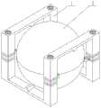
图1是本发明的结构示意图;Fig. 1 is a structural representation of the present invention;
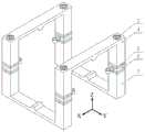
图2是本发明中压电振子的结构示意图;Fig. 2 is a structural schematic diagram of a piezoelectric vibrator in the present invention;
图3是本发明中夹持件的结构示意图;Fig. 3 is a schematic structural view of a clip in the present invention;
图4是本发明中各个压电陶瓷片的极化方向以及激励信号施加示意图;Fig. 4 is a schematic diagram of the polarization direction and excitation signal application of each piezoelectric ceramic sheet in the present invention;
图5是本发明中球形转子的结构示意图;Fig. 5 is the structural representation of spherical rotor among the present invention;
图6(a)是本发明中压电振子三阶弯振模态时在X轴正、负方向上的对比示意图;Fig. 6(a) is a comparative schematic diagram of the piezoelectric vibrator in the third-order bending vibration mode in the positive and negative directions of the X-axis in the present invention;
图6(b)是本发明中压电振子三阶弯振模态时在Y轴正、负方向上的对比示意图;Fig. 6(b) is a comparative schematic diagram of the piezoelectric vibrator in the third-order bending vibration mode of the present invention in the positive and negative directions of the Y-axis;
图7是本发明中压电振子一阶纵振模态时在Z轴正、负方向上的对比示意图;Fig. 7 is a comparative schematic diagram of the piezoelectric vibrator in the first-order longitudinal vibration mode in the positive and negative directions of the Z axis in the present invention;
图8是本发明绕X轴转动时的工作状态示意图;Fig. 8 is a schematic diagram of the working state of the present invention when it rotates around the X axis;
图9是本发明绕Y轴转动时的工作状态示意图;Fig. 9 is a schematic diagram of the working state of the present invention when it rotates around the Y axis;
图10是本发明绕Z轴转动时的工作状态示意图。Fig. 10 is a schematic diagram of the working state of the present invention when it rotates around the Z axis.
图中,1-压电振子,2-球形转子,3-第三振动梁的预紧螺栓,4-第三振动梁的上梁,5-第三振动梁的第一压电陶瓷片,6-第三振动梁的夹持件,7-第三振动梁的下梁,8-夹持部,9-柔性铰链,10-限位部,11-第一球壳,12-第二球壳,13-第一固定筒,14-第二固定筒,15-限位销,16-限位孔,17-预紧弹簧。In the figure, 1-piezoelectric vibrator, 2-spherical rotor, 3-the pre-tightening bolt of the third vibration beam, 4-the upper beam of the third vibration beam, 5-the first piezoelectric ceramic sheet of the third vibration beam, 6 -Clamping part of the third vibrating beam, 7-lower beam of the third vibrating beam, 8-clamping part, 9-flexible hinge, 10-limiting part, 11-first spherical shell, 12-second spherical shell , 13-the first fixed cylinder, 14-the second fixed cylinder, 15-limit pin, 16-limit hole, 17-preload spring.
具体实施方式Detailed ways
下面结合附图对本发明的技术方案做进一步的详细说明:Below in conjunction with accompanying drawing, technical scheme of the present invention is described in further detail:
本发明可以以许多不同的形式实现,而不应当认为限于这里所述的实施例。相反,提供这些实施例以便使本公开透彻且完整,并且将向本领域技术人员充分表达本发明的范围。在附图中,为了清楚起见放大了组件。This invention may be embodied in many different forms and should not be construed as limited to the embodiments set forth herein. Rather, these embodiments are provided so that this disclosure will be thorough and complete, and will fully convey the scope of the invention to those skilled in the art. In the drawings, components are exaggerated for clarity.
应当理解,尽管这里可以使用术语第一、第二、第三等描述各个元件、组件和/或部分,但这些元件、组件和/或部分不受这些术语限制。这些术语仅仅用于将元件、组件和/或部分相互区分开来。因此,下面讨论的第一元件、组件和/或部分在不背离本发明教学的前提下可以成为第二元件、组件或部分。It should be understood that although the terms first, second, third etc. may be used herein to describe various elements, components and/or sections, these elements, components and/or sections should not be limited by these terms. These terms are only used to distinguish one element, component and/or section from another. Thus, a first element, component and/or section discussed below could be termed a second element, component or section without departing from the teachings of the present invention.
如图1所示,本发明公开了一种纵弯模态复合的四足多自由度超声电机,包含压电振子和球形转子;As shown in Figure 1, the present invention discloses a four-legged multi-degree-of-freedom ultrasonic motor with composite longitudinal-bending modes, including a piezoelectric vibrator and a spherical rotor;
如图2所示,所述压电振子包含第一至第四振动梁、以及第一至第四横梁;As shown in Figure 2, the piezoelectric vibrator includes first to fourth vibration beams and first to fourth beams;
所述第一至第四振动梁结构相同,均包含上梁、夹持件、下梁、第一至第四压电陶片、以及预紧螺栓;The first to fourth vibrating beams have the same structure, and all include an upper beam, a clamping piece, a lower beam, first to fourth piezoelectric ceramic sheets, and pre-tightening bolts;
所述上梁、下梁为形状相同的正四棱柱,上梁的上端沿其轴线设有和所述预紧螺栓相匹配的沉头通孔,下梁上端的中心设有和所述预紧螺栓相匹配的螺纹盲孔;The upper beam and the lower beam are square prisms with the same shape, the upper end of the upper beam is provided with a countersunk through hole matching the pre-tightening bolt along its axis, and the center of the upper end of the lower beam is provided with a countersunk hole matching the pre-tightening bolt. Matching threaded blind holes;
如图3所示,所述夹持件结构包含夹持部、柔性铰链和限位部,所述夹持部为横截面和上梁横截面形状相同的正四棱柱;所述限位部为上开下口的空心圆柱体;所述限位部的侧壁通过所述柔性铰链和所述夹持部的一个侧壁的中心垂直固连,使得限位部的轴线平行于夹持部的轴线,且所述夹持部沿其轴线设有供所述预紧螺栓穿过的通孔;As shown in Figure 3, the structure of the clamping member includes a clamping part, a flexible hinge and a limiting part, and the clamping part is a regular quadrangular prism with the same cross-sectional shape as that of the upper beam; the limiting part is an upper A hollow cylinder with a lower opening; the side wall of the limiting part is vertically fixed to the center of a side wall of the clamping part through the flexible hinge, so that the axis of the limiting part is parallel to the axis of the clamping part , and the clamping portion is provided with a through hole along its axis for the pre-tightening bolt to pass through;
所述第一至四压电陶片的形状和所述上梁横截面的形状相同,中心均设有供所述预紧螺栓穿过的通孔,且第一、第四压电陶瓷片采用二分区压电陶瓷片,第二、第三压电陶瓷片采用单分区压电陶瓷片;The shapes of the first to four piezoelectric ceramic sheets are the same as the shape of the cross-section of the upper beam, and there are through holes in the center for the pre-tightening bolts to pass through, and the first and fourth piezoelectric ceramic sheets are made of Two-part piezoelectric ceramic sheets, the second and third piezoelectric ceramic sheets use single-partition piezoelectric ceramic sheets;
所述预紧螺栓从上梁的沉头通孔穿入,依次穿过第一压电陶瓷片、第二压电陶瓷片、夹持部、第三压电陶瓷片、第四压电陶瓷片上的通孔后和所述下梁的螺纹盲孔螺纹相连,将第一压电陶瓷片、第二压电陶瓷片、夹持部、第三压电陶瓷片、第四压电陶瓷片夹紧在上梁、下梁之间,第一、第四压电陶瓷片的分界线相互垂直;所述第二、第三压电陶瓷片的极化方向均沿厚度方向朝下;所述第一、第四压电陶瓷片均沿厚度方向极化,且两个分区的极化方向相反;The pre-tightening bolt penetrates through the countersunk through hole of the upper beam, and passes through the first piezoelectric ceramic sheet, the second piezoelectric ceramic sheet, the clamping part, the third piezoelectric ceramic sheet, and the fourth piezoelectric ceramic sheet in sequence. After the through hole is connected with the threaded blind hole of the lower beam, the first piezoelectric ceramic sheet, the second piezoelectric ceramic sheet, the clamping part, the third piezoelectric ceramic sheet, and the fourth piezoelectric ceramic sheet are clamped Between the upper beam and the lower beam, the boundary lines of the first and fourth piezoelectric ceramic sheets are perpendicular to each other; the polarization directions of the second and third piezoelectric ceramic sheets are both downward along the thickness direction; the first , the fourth piezoelectric ceramic sheet is polarized along the thickness direction, and the polarization directions of the two partitions are opposite;
所述第一、第二振动梁的上端分别和第一横梁的两端垂直固连,第三、第四振动梁的两端分别和第二横梁的两端垂直固连,第一、第四振动梁的下端分别和第三横梁的两端垂直固连,第二、第三振动梁的下端分别和第四横梁的两端垂直固连;第一横梁下端面、第二横梁下端面、第三横梁上端面、第四横梁上端面的中心处均设有凸起的驱动足;所述第一、第二振动梁的夹持件相向,第三、第四振动梁的夹持件相向;The upper ends of the first and second vibrating beams are respectively vertically fixed to the two ends of the first beam, and the two ends of the third and fourth vibrating beams are respectively vertically fixed to the two ends of the second beam. The lower ends of the vibrating beams are respectively vertically fixed to the two ends of the third beam, and the lower ends of the second and third vibrating beams are respectively vertically fixed to the two ends of the fourth beam; the lower end of the first beam, the lower end of the second beam, the second The center of the upper end surface of the third beam and the upper end surface of the fourth beam are provided with protruding driving feet; the clamping parts of the first and second vibrating beams face each other, and the clamping parts of the third and fourth vibrating beams face each other;
所述驱动足为横截面为等腰梯形的柱体,包含两个呈等腰梯形的端面、以及依次首位相连的第一至第四侧面;驱动足的第一侧面的面积小于其第三侧面;驱动足的第三侧面和驱动足所在横梁固连、两个端面分别和驱动足所在横梁的两侧共面;The driving foot is a cylinder with an isosceles trapezoidal cross section, including two isosceles trapezoidal end faces, and the first to fourth sides connected in turn; the area of the first side of the driving foot is smaller than that of the third side ; The third side of the driving foot is fixedly connected to the beam where the driving foot is located, and the two end faces are respectively coplanar with the two sides of the beam where the driving foot is located;
所述第一至第四振动梁的第一压电陶瓷片的分界线相互平行,均垂直于所述第一横梁;所述第一振动梁第一压电陶瓷片远离第二振动梁的分区、第一振动梁第四压电陶瓷片远离第四振动梁的分区、第二振动梁第一压电陶瓷片靠近第一振动梁的分区、第二振动梁第四压电陶瓷片远离第三振动梁的分区、第三振动梁第一压电陶瓷片靠近第四振动梁的分区、第三振动梁第四压电陶瓷片靠近第二振动梁的分区、第四振动梁第一压电陶瓷片远离第三振动梁的分区、第四振动梁第四压电陶瓷片靠近第一振动梁的分区均沿厚度方向朝上极化,如图4所示;The dividing lines of the first piezoelectric ceramic sheets of the first to fourth vibrating beams are parallel to each other and are perpendicular to the first beam; the first piezoelectric ceramic sheets of the first vibrating beam are far away from the partition of the second vibrating beam , the fourth piezoelectric ceramic sheet of the first vibrating beam is far away from the partition of the fourth vibrating beam, the first piezoelectric ceramic sheet of the second vibrating beam is close to the partition of the first vibrating beam, and the fourth piezoelectric ceramic sheet of the second vibrating beam is far away from the third The partition of the vibrating beam, the partition of the first piezoelectric ceramic sheet of the third vibrating beam close to the fourth vibrating beam, the partition of the fourth piezoelectric ceramic sheet of the third vibrating beam close to the second vibrating beam, the first piezoelectric ceramic of the fourth vibrating beam The partition of the sheet away from the third vibrating beam, and the partition of the fourth piezoelectric ceramic sheet of the fourth vibrating beam close to the first vibrating beam are all polarized upward along the thickness direction, as shown in Figure 4;
如图5所示,所述球形转子包含第一球壳、第二球壳和预紧模块;As shown in Figure 5, the spherical rotor includes a first spherical shell, a second spherical shell and a preload module;
所述第一至第二球壳结构相同,均为高度等于半径的空心半球体;The first to second spherical shells have the same structure, and they are all hollow hemispheres whose height is equal to the radius;
所述预紧模块包含第一固定筒、第二固定筒、预紧弹簧、以及N个限位销,N为大于等于3的自然数,优先取4;The preload module includes a first fixed cylinder, a second fixed cylinder, a preload spring, and N limit pins, where N is a natural number greater than or equal to 3, preferably 4;
所述第一固定筒、第二固定筒为结构相同的圆柱体,其中,所述第一固定筒一端和所述第一球壳内壁的中心固连,第一固定筒的轴线经过第一球壳的球心;第二固定筒一端和所述第二球壳内壁的中心固连,第二固定筒的轴线经过第二球壳的球心;The first fixed cylinder and the second fixed cylinder are cylinders with the same structure, wherein one end of the first fixed cylinder is fixedly connected to the center of the inner wall of the first spherical shell, and the axis of the first fixed cylinder passes through the first ball The spherical center of the shell; one end of the second fixed cylinder is fixedly connected with the center of the inner wall of the second spherical shell, and the axis of the second fixed cylinder passes through the spherical center of the second spherical shell;
所述N个限位销周向均匀设置在所述第一固定筒靠近第一球壳球心的端面上,均和第一固定筒靠近第一球壳球心的的端面垂直固连;The N limit pins are evenly arranged on the end surface of the first fixing cylinder near the center of the first spherical shell in the circumferential direction, and are vertically fixed to the end surface of the first fixing cylinder close to the center of the first spherical shell;
所述第二固定筒靠近第二球壳球心的端面上周向设有N个和所述限位销一一对应配合的限位孔;The end surface of the second fixing cylinder close to the center of the second spherical shell is provided with N position-limiting holes in a one-to-one correspondence with the position-limiting pins;
所述第一球壳、第二球壳均置于所述压电振子中;所述第一球壳的边缘和第二球壳的边缘贴合,第一固定筒上的N个限位销一一对应插入第二固定筒上的N个限位孔中;所述预紧弹簧设置在N个限位销中间,一端和所述第一固定筒相抵、另一端和所述第二固定筒相抵,使得球形转子的外表分别和第一至第四横梁上的驱动足、第一至第四振动梁的限位部相抵。Both the first spherical shell and the second spherical shell are placed in the piezoelectric vibrator; the edge of the first spherical shell and the edge of the second spherical shell are attached, and the N limit pins on the first fixing cylinder Insert one by one into the N limit holes on the second fixed cylinder; the pre-tension spring is arranged in the middle of the N limit pins, one end is against the first fixed cylinder, and the other end is connected to the second fixed cylinder The offsetting makes the outer surface of the spherical rotor respectively abut against the driving feet on the first to the fourth beams and the limiting parts of the first to the fourth vibrating beams.
本发明还公开了一种该纵弯模态复合的四足多自由度超声电机的激励方法,其特征在于,包含以下步骤:The invention also discloses an excitation method of the four-legged multi-degree-of-freedom ultrasonic motor with composite longitudinal-bending modes, which is characterized in that it includes the following steps:
令球形转子的球心为笛卡尔坐标原点,从第二振动梁沿着第一横梁指向第一振动梁的方向为X轴正方向,从第一振动梁沿着第三横梁指向第二振动梁的方向为Y轴正方向,沿着第一振动梁朝上的方向为Z轴正方向;并令第一至第四振动梁的第一压电陶瓷片为第一压电陶瓷片组,第一至第四振动梁的第二、第三压电陶瓷片为第二压电陶瓷片组,第一至第四振动梁的第四压电陶瓷片为第三压电陶瓷片组;Let the center of the spherical rotor be the origin of Cartesian coordinates, the direction from the second vibrating beam to the first vibrating beam along the first beam is the positive direction of the X axis, and from the first vibrating beam to the second vibrating beam along the third beam The direction along the first vibration beam is the positive direction of the Y axis, and the upward direction along the first vibration beam is the positive direction of the Z axis; and the first piezoelectric ceramic sheets of the first to fourth vibration beams are the first piezoelectric ceramic sheet group, and the first piezoelectric ceramic sheet group The second and third piezoelectric ceramic sheets of the first to fourth vibration beams are the second piezoelectric ceramic sheet group, and the fourth piezoelectric ceramic sheets of the first to fourth vibration beams are the third piezoelectric ceramic sheet group;
如果需要驱动球形转子绕X轴旋转:If you need to drive the spherical rotor to rotate around the X axis:
对第三压电陶瓷片组施加第一激励信号,对第二压电陶瓷片组施加第二激励信号,所述第一、二激励信号均为同频幅值相等的交流谐波信号,其中,第一激励信号在时间相位差上超前第二激励信号π/2,使压电振子上同时激发出一阶纵振模态和Y轴方向的三阶弯振模态,如图6(b)、图7所示,通过一阶纵振模态和三阶弯振模态的耦合振动,压电振子的驱动足表面质点产生垂直于X轴的微幅椭圆运动,经摩擦作用驱动球形转子绕X轴旋转,如图8所示;如果需要绕X轴反向旋转,将第二激励信号取反即可;Applying a first excitation signal to the third piezoelectric ceramic sheet group, applying a second excitation signal to the second piezoelectric ceramic sheet group, the first and second excitation signals are AC harmonic signals with the same frequency and equal amplitude, wherein , the first excitation signal leads the second excitation signal by π/2 in time phase difference, so that the piezoelectric vibrator simultaneously excites the first-order longitudinal vibration mode and the third-order bending vibration mode in the Y-axis direction, as shown in Figure 6(b ), as shown in Fig. 7, through the coupled vibration of the first-order longitudinal vibration mode and the third-order bending vibration mode, the surface particle of the driving foot of the piezoelectric vibrator produces a slight elliptical motion perpendicular to the X-axis, and drives the spherical rotor through friction Rotate around the X-axis, as shown in Figure 8; if you need to rotate around the X-axis in reverse, just invert the second excitation signal;
如果需要驱动球形转子绕Y轴旋转:If you need to drive the spherical rotor to rotate around the Y axis:
对第一压电陶瓷片组施加第一激励信号,对第二压电陶瓷片组施加第二激励信号,所述第一、二激励信号均为同频幅值相等的交流谐波信号,其中,第一激励信号在时间相位差上超前第二激励信号π/2,使压电振子上同时激发出一阶纵振模态和X轴方向的三阶弯振模态,如图6(a)、图7所示,通过一阶纵振模态和三阶弯振模态的耦合振动,压电振子的驱动足表面质点产生垂直于Y轴的微幅椭圆运动,经摩擦作用驱动球形转子绕Y轴旋转,如图9所示;如果需要绕Y轴反向旋转,将第二激励信号取反即可;Applying a first excitation signal to the first piezoelectric ceramic sheet group, and applying a second excitation signal to the second piezoelectric ceramic sheet group, the first and second excitation signals are AC harmonic signals with the same frequency and equal amplitude, wherein , the first excitation signal leads the second excitation signal by π/2 in time phase difference, so that the piezoelectric vibrator simultaneously excites the first-order longitudinal vibration mode and the third-order bending vibration mode in the X-axis direction, as shown in Figure 6 (a ), as shown in Figure 7, through the coupled vibration of the first-order longitudinal vibration mode and the third-order bending vibration mode, the surface particle of the driving foot of the piezoelectric vibrator produces a slight elliptical motion perpendicular to the Y-axis, and drives the spherical rotor through friction Rotate around the Y axis, as shown in Figure 9; if you need to rotate around the Y axis in the opposite direction, just invert the second excitation signal;
如果需要驱动球形转子绕Z轴旋转:If you need to drive the spherical rotor to rotate around the Z axis:
对第三压电陶瓷片组施加第一激励信号,对第一压电陶瓷片组施加第二激励信号,applying a first excitation signal to the third piezoelectric ceramic sheet group, and applying a second excitation signal to the first piezoelectric ceramic sheet group,
所述第一、二激励信号均为同频幅值相等的交流谐波信号,其中,第一激励信号在时间相位差上超前第二激励信号π/2,使压电振子上同时激发出两个互相正交的三阶弯振模态,如图6(a)、图6(b)所示,通过两个正交的三阶弯振模态的耦合振动,压电振子的驱动足表面质点产生垂直于Z轴的微幅椭圆运动,经摩擦作用驱动球形转子绕Z轴旋转,如图10所示;如果需要绕Z轴反向旋转,将第二激励信号取反即可。The first and second excitation signals are AC harmonic signals with the same frequency and equal amplitude, wherein the first excitation signal is ahead of the second excitation signal by π/2 in time phase difference, so that the piezoelectric vibrator simultaneously excites two Two mutually orthogonal third-order bending vibration modes, as shown in Figure 6(a) and Figure 6(b), through the coupling vibration of two orthogonal third-order bending vibration modes, the driving foot surface of the piezoelectric vibrator The particle produces a slight elliptical motion perpendicular to the Z-axis, and drives the spherical rotor to rotate around the Z-axis through friction, as shown in Figure 10; if it is necessary to reverse the rotation around the Z-axis, just invert the second excitation signal.
本技术领域技术人员可以理解的是,除非另外定义,这里使用的所有术语(包括技术术语和科学术语)具有与本发明所属领域中的普通技术人员的一般理解相同的意义。还应该理解的是,诸如通用字典中定义的那些术语应该被理解为具有与现有技术的上下文中的意义一致的意义,并且除非像这里一样定义,不会用理想化或过于正式的含义来解释。Those skilled in the art can understand that, unless otherwise defined, all terms (including technical terms and scientific terms) used herein have the same meaning as commonly understood by those of ordinary skill in the art to which this invention belongs. It should also be understood that terms such as those defined in commonly used dictionaries should be understood to have a meaning consistent with the meaning in the context of the prior art, and unless defined as herein, are not to be interpreted in an idealized or overly formal sense explain.
以上所述的具体实施方式,对本发明的目的、技术方案和有益效果进行了进一步详细说明,所应理解的是,以上所述仅为本发明的具体实施方式而已,并不用于限制本发明,凡在本发明的精神和原则之内,所做的任何修改、等同替换、改进等,均应包含在本发明的保护范围之内。The specific embodiments described above have further described the purpose, technical solutions and beneficial effects of the present invention in detail. It should be understood that the above descriptions are only specific embodiments of the present invention and are not intended to limit the present invention. Any modifications, equivalent replacements, improvements, etc. made within the spirit and principles of the present invention shall be included within the protection scope of the present invention.
Claims (4)
Priority Applications (1)
| Application Number | Priority Date | Filing Date | Title |
|---|---|---|---|
| CN202211030949.7ACN116073697A (en) | 2022-08-26 | 2022-08-26 | Four-foot multi-freedom-degree ultrasonic motor composited by longitudinal bending modes and excitation method thereof |
Applications Claiming Priority (1)
| Application Number | Priority Date | Filing Date | Title |
|---|---|---|---|
| CN202211030949.7ACN116073697A (en) | 2022-08-26 | 2022-08-26 | Four-foot multi-freedom-degree ultrasonic motor composited by longitudinal bending modes and excitation method thereof |
Publications (1)
| Publication Number | Publication Date |
|---|---|
| CN116073697Atrue CN116073697A (en) | 2023-05-05 |
Family
ID=86168811
Family Applications (1)
| Application Number | Title | Priority Date | Filing Date |
|---|---|---|---|
| CN202211030949.7APendingCN116073697A (en) | 2022-08-26 | 2022-08-26 | Four-foot multi-freedom-degree ultrasonic motor composited by longitudinal bending modes and excitation method thereof |
Country Status (1)
| Country | Link |
|---|---|
| CN (1) | CN116073697A (en) |
Cited By (1)
| Publication number | Priority date | Publication date | Assignee | Title |
|---|---|---|---|---|
| CN117277866A (en)* | 2023-11-22 | 2023-12-22 | 吉林大学 | A four-degree-of-freedom cross-scale stepper actuator based on piezoelectric drive |
- 2022
- 2022-08-26CNCN202211030949.7Apatent/CN116073697A/enactivePending
Cited By (2)
| Publication number | Priority date | Publication date | Assignee | Title |
|---|---|---|---|---|
| CN117277866A (en)* | 2023-11-22 | 2023-12-22 | 吉林大学 | A four-degree-of-freedom cross-scale stepper actuator based on piezoelectric drive |
| CN117277866B (en)* | 2023-11-22 | 2024-01-23 | 吉林大学 | Four-degree-of-freedom trans-scale stepping actuator based on piezoelectric driving |
Similar Documents
| Publication | Publication Date | Title |
|---|---|---|
| Zhang et al. | Development of a novel two-DOF pointing mechanism using a bending–bending hybrid piezoelectric actuator | |
| Zhang et al. | A 3-DOF piezoelectric micromanipulator based on symmetric and antisymmetric bending of a cross-shaped beam | |
| CN109245605B (en) | Two-degree-of-freedom piezoelectric driving mechanical arm and driving method thereof | |
| CN106533248B (en) | Monostator three-freedon supersonic motor and its working method | |
| CN109245604B (en) | Sandwich type piezoelectric mechanical arm and driving method thereof | |
| CN110238873B (en) | Orthogonal piezoelectric joint mechanism and control method thereof | |
| Chang et al. | Review on multiple‐degree‐of‐freedom cross‐scale piezoelectric actuation technology | |
| CN113224972A (en) | Single-stator three-degree-of-freedom spherical ultrasonic motor and excitation method thereof | |
| US8238011B1 (en) | MEMS device with off-axis actuator | |
| CN108436965B (en) | An underwater fully open joint mechanism and its working method | |
| CN116073697A (en) | Four-foot multi-freedom-degree ultrasonic motor composited by longitudinal bending modes and excitation method thereof | |
| CN107481767A (en) | Drive components and flexible precision positioning platform | |
| CN105634327B (en) | A kind of two-degree of freedom spherical ultrasound electric machine and its control method | |
| CN115459626B (en) | Patch frame type stator multi-degree-of-freedom ultrasonic motor and excitation method thereof | |
| CN108429486A (en) | Combined planar three-degree-of-freedom ultrasonic motor vibrator and its driving method | |
| CN113776994B (en) | Piezoelectric-excitation annular-surface micro-control device and working method thereof | |
| CN116191929B (en) | Three-degree-of-freedom piezoelectric actuator and working method thereof | |
| CN209970737U (en) | A piezoelectric joint mechanism of a robotic arm | |
| CN117761887A (en) | Three-degree-of-freedom fast reflex mirror driven by threaded piezoelectric actuator and its working method | |
| CN109378993B (en) | Double-actuator patch type piezoelectric vibrator and working method thereof | |
| Wang et al. | Design of a compact compliant constant-force XY precision positioning stage | |
| CN111313749A (en) | Surface-mounted piezoelectric-driven two-degree-of-freedom underwater mechanical arm and driving method thereof | |
| Bian et al. | A novel miniature multi-DOF three-ring-shaped piezoelectric actuator for small and lightweight robot joints | |
| CN115163736A (en) | Stewart mechanism with variable rigidity | |
| CN109093598A (en) | A kind of freedom degree parallel connection micromotion platform |
Legal Events
| Date | Code | Title | Description |
|---|---|---|---|
| PB01 | Publication | ||
| PB01 | Publication | ||
| SE01 | Entry into force of request for substantive examination | ||
| SE01 | Entry into force of request for substantive examination |