CN116068636A - Method for monitoring design rationality of maximum offset of seismic acquisition data observation system - Google Patents
Method for monitoring design rationality of maximum offset of seismic acquisition data observation systemDownload PDFInfo
- Publication number
- CN116068636A CN116068636ACN202111299631.4ACN202111299631ACN116068636ACN 116068636 ACN116068636 ACN 116068636ACN 202111299631 ACN202111299631 ACN 202111299631ACN 116068636 ACN116068636 ACN 116068636A
- Authority
- CN
- China
- Prior art keywords
- offset
- maximum offset
- observation system
- design
- work area
- Prior art date
- Legal status (The legal status is an assumption and is not a legal conclusion. Google has not performed a legal analysis and makes no representation as to the accuracy of the status listed.)
- Pending
Links
Images


Classifications
- G—PHYSICS
- G01—MEASURING; TESTING
- G01V—GEOPHYSICS; GRAVITATIONAL MEASUREMENTS; DETECTING MASSES OR OBJECTS; TAGS
- G01V1/00—Seismology; Seismic or acoustic prospecting or detecting
- G01V1/28—Processing seismic data, e.g. for interpretation or for event detection
- G01V1/30—Analysis
Landscapes
- Engineering & Computer Science (AREA)
- Remote Sensing (AREA)
- Physics & Mathematics (AREA)
- Life Sciences & Earth Sciences (AREA)
- Acoustics & Sound (AREA)
- Environmental & Geological Engineering (AREA)
- Geology (AREA)
- General Life Sciences & Earth Sciences (AREA)
- General Physics & Mathematics (AREA)
- Geophysics (AREA)
- Geophysics And Detection Of Objects (AREA)
Abstract
Description
Translated fromChinese技术领域technical field
本发明涉及油田地震资料采集技术领域,特别是涉及到一种监控地震采集资料观测系统最大偏移距设计合理性的方法。The invention relates to the technical field of oilfield seismic data acquisition, in particular to a method for monitoring the design rationality of the maximum offset distance of an observation system for seismic acquisition data.
背景技术Background technique
在进行地震资料采集时,首先要根据工区地质地震条件以及地质任务进行观测系统的设计。观测系统最大偏移距的设计需要满足所采集到的资料覆盖至目的层深度。实际应用过程中最大炮检距的选择应重点考虑以下因素:主要目的层的深度;动校拉伸率不宜超过12.5%;速度分析的精度误差不宜高于5%;保证反射系数稳定;干扰波对炮检距的影响;考虑叠前偏移的需要:满足偏移时可以归位95%的绕射波能量。一般情况下,最大偏移距设计越大,所采集到的目的层越深,总成本越高。为了降低成本,满足采集目的需求,需要监控最大偏移距设计的合理性。When collecting seismic data, the observation system must first be designed according to the geological and seismic conditions of the work area and the geological tasks. The design of the maximum offset of the observation system needs to meet the coverage of the collected data to the depth of the target layer. The selection of the maximum offset in the actual application process should focus on the following factors: the depth of the main target layer; the dynamic correction stretch rate should not exceed 12.5%; the accuracy error of the velocity analysis should not be higher than 5%; ensure the stability of the reflection coefficient; The impact on offset; consider the needs of pre-stack migration: 95% of the diffracted wave energy can be homing when migration is satisfied. In general, the larger the maximum offset design is, the deeper the target layer is collected and the higher the total cost. In order to reduce the cost and meet the requirements of the collection purpose, it is necessary to monitor the rationality of the maximum offset design.
随着勘探采集程度的加深,在实际的应用处理中发现,设计因素考虑在内的地震勘探采集中,需要对采集参数进行论证,在对最大偏移距的论证过程中,常常采用分偏移距叠加的思路判断最大偏移距是否能够满足要求。对于复杂构造区即使设计的观测系统最大偏移距满足叠加剖面上深层目的层的成像及覆盖次数要求,偏移处理中,经过层位构造的真实归位,处理中偏移剖面显示采集到的资料也能未达到目的层深度或目的层显示的覆盖次数不够。因此在地震资料采集前进行观测系统设计及论证时,就应考虑偏移归位的影响,以此为依据监控最大偏移距设计的合理性。With the deepening of exploration acquisition, it is found in the actual application process that in the seismic exploration acquisition with design factors taken into consideration, it is necessary to demonstrate the acquisition parameters. In the process of demonstrating the maximum offset distance, the sub-offset Judging whether the maximum offset distance can meet the requirements based on the idea of distance superposition. For complex structural areas, even if the maximum offset distance of the designed observation system meets the imaging and coverage times requirements of the deep target layer on the stacked section, during the migration process, after the real homing of the horizon structure, the migration section during the processing shows the collected The data can also not reach the depth of the target layer or the coverage of the target layer display is not enough. Therefore, when designing and demonstrating the observation system before seismic data acquisition, the influence of offset homing should be considered, and the rationality of the maximum offset design should be monitored based on this.
申请号:201910816090.4的中国专利申请中公开了一种观测系统的调整方法,该方法通过目标区域划分网格面元,在目标区域内布置炮检对,获取每一个网格面元内的炮检对中心点的离散度,通过离散度的大小选取目标网格面元,调整目标网格面元内的炮检对中心点的离散度减小至所述离散度预设值或减小到所述离散度预设值以下。该发明通过获取每一个网格面元内的炮检对中心点的离散度,能够了解各网格面元内的炮检对中心点的离散程度,以便针对性地对离散度较大的网格面元内的炮检对中心点的位置进行调整从而最大程度地减小网格面元内的炮检对中心点的离散度,提高精细构造部位成像的保真程度。The Chinese patent application with application number: 201910816090.4 discloses an adjustment method of the observation system. This method divides the grid cells by the target area, arranges the shot detection pairs in the target area, and obtains the shot detection in each grid cell. For the dispersion of the central point, select the target grid surface element by the size of the dispersion, and adjust the dispersion of the shot detection in the target grid surface element to the central point to reduce to the discrete degree preset value or to the specified value. The above-mentioned dispersion preset value is below. By obtaining the dispersion degree of the offset center point in each grid cell, the invention can understand the dispersion degree of the offset center point in each grid cell, so as to target the network with a large dispersion The position of the offset center point in the grid bin is adjusted to minimize the dispersion of the offset center point in the grid bin and improve the fidelity of the imaging of fine structure parts.
文献《基于复杂构造区的采集观测系统设计与优化方法》引入了全波形反演到面向复杂地质目标的采集观测系统设计,讨论了观测系统成像分辨率的影响因素,并进行不同参数观测系统的对比分析。该研究方法可为地震采集观测系统设计及其优化提供一个强有力的支撑工具,为精细化地震采集方案设计提供参考。该方法仅对最大偏移距进行了大间隔测试,并未对实际资料进行分析。The literature "Design and Optimization Method of Acquisition and Observation System Based on Complex Structural Areas" introduces full waveform inversion to the design of acquisition and observation system for complex geological targets, discusses the factors affecting the imaging resolution of the observation system, and conducts the analysis of observation systems with different parameters. Comparative analysis. This research method can provide a powerful supporting tool for the design and optimization of seismic acquisition observation system, and provide a reference for the design of refined seismic acquisition scheme. This method only conducts a large-interval test on the maximum offset, and does not analyze the actual data.
文献《基于实际数据地震属性的观测系统评价方法》提出了基于实际地震数据驱动的地震属性的观测系统设计评价方法,主要方法为:选择不同类型的地震波,建立时-空变的能量、频率等地震属性与炮检距的关系曲线(量板),通过量板定量分析不同观测系统设计方案的采集“脚印”分布规律,提高复杂地区地震资料的信噪比和保真度。该方法主要适用于具有大量实际采集资料的工区。The literature "Evaluation Method of Observation System Based on Seismic Attributes of Actual Data" proposes an evaluation method of observation system design based on seismic attributes driven by actual seismic data. The main methods are: selecting different types of seismic waves, establishing time-space variable energy and frequency The relationship curve (quantity plate) between seismic attributes and offsets can be used to quantitatively analyze the distribution of acquisition “footprints” of different observation system design schemes through the quantitative plate, and improve the signal-to-noise ratio and fidelity of seismic data in complex areas. This method is mainly suitable for work areas with a large amount of actual collected data.
文献《高密度三维地震观测系统设计技术与应用》基于前期丰富的地震和地质资料,提出了一套适用于成熟勘探区的高密度三维地震观测系统设计技术。首先将已有高密度采集数据的退化处理结果用于炮道密度的论证,以实现经济成本和勘探效果的平衡,并用于指导本地区新一轮高密度三维地震观测系统的设计:然后对面元边长、最大炮检距、接收线距等主要的观测系统参数,充分利用已有的地震、地质资料,基于目的层地震地质参数模型进行观测系统参数宏观论证:再建立目标地质模型,通过波动方程正演进行观测系统参数精细论证。该文献中对最大偏移距没有进行详细的测试,仅仅给出了采集标准中的范围。The document "Design Technology and Application of High-Density 3D Seismic Observation System" proposes a set of high-density 3D seismic observation system design technology suitable for mature exploration areas based on the rich seismic and geological data in the early stage. Firstly, the degraded processing results of the existing high-density acquisition data are used for the demonstration of shot density, in order to achieve the balance between economic cost and exploration effect, and to guide the design of a new round of high-density 3D seismic observation system in this area: Main observation system parameters such as side length, maximum offset distance, receiving line distance, etc., make full use of the existing seismic and geological data, and conduct a macroscopic demonstration of the observation system parameters based on the seismic and geological parameter model of the target layer: then establish the target geological model, through the fluctuation Equation forward evolution carries out fine demonstration of observation system parameters. There is no detailed test on the maximum offset in this document, only the range in the acquisition standard is given.
文献《基于地震照明分析的观测系统参数优化》为了调整和优化地震采集参数,使观测系统更匹配目标区的地质条件从而提高地震成像精度,该文以某地区三维项目为例,利用单程波动照明分析方法,通过对比不同偏移距的地震资料照明效果,优选出最佳的采集参数。该文给出了一种优化最大偏移距的方法设想,但并未在实际资料中得到验证。The document "Observation System Parameter Optimization Based on Seismic Illumination Analysis" In order to adjust and optimize the seismic acquisition parameters, make the observation system better match the geological conditions of the target area and improve the accuracy of seismic imaging, this paper takes a 3D project in a certain area as an example, using one-way fluctuation illumination The analysis method, by comparing the lighting effect of seismic data with different offsets, optimizes the best acquisition parameters. This paper proposes a method to optimize the maximum offset, but it has not been verified in actual data.
文献《面向叠前偏移成像的观测系统优选方法在山地复杂构造区的测试应用》针对山地复杂地表及复杂构造区,设计了一种有效的观测系统优选技术,以期改善复杂构造区地震成像质量。构建含起伏地表和近地表渐变速度信息的数学模型,通过弹性波波动方程正演,得到针对不同野外观测系统参数的地震数据记录,然后进行叠前深度偏移成像处理,最终对比分析不同观测系统参数对偏移成像质量的影响,以此来优选观测系统参数。同时通过应用实际地震资料对比分析,进一步证明了基于波动方程正演的、面向叠前偏移的观测系统参数论证技术对于解决复杂构造观测系统设计和成像问题具有优势。在进行偏移距的测试时仅仅给出了大范围的几组,无法真实判断具体偏移距。The literature "Testing and Application of Observation System Optimization Method for Prestack Migration Imaging in Complex Mountainous Tectonic Areas" designed an effective observation system optimization technology for complex mountainous surface and complex structural areas, in order to improve the quality of seismic imaging in complex structural areas . Construct a mathematical model containing gradual velocity information on the undulating surface and near-surface, and obtain seismic data records for different field observation system parameters through forward modeling of the elastic wave equation, then perform pre-stack depth migration imaging processing, and finally compare and analyze different observation systems The influence of parameters on the migration imaging quality is used to optimize the observation system parameters. At the same time, through the comparison and analysis of actual seismic data, it is further proved that the observation system parameter demonstration technology based on wave equation forward modeling and oriented to prestack migration has advantages in solving complex structural observation system design and imaging problems. When testing the offset distance, only a few large-scale groups are given, and the specific offset distance cannot be truly judged.
文献《西部复杂山地地震勘探关键技术应用研究》利用射线追踪计算各目的层界面上共反射点的“覆盖次数”,而相应的能量用波动方程来计算。两者结合,来综合分析各目的层的照明情况,分析各目的层界面上共反射点的“覆盖次数”和能量。对特定勘探目标,分析各点的覆盖次数和能量主要来哪一范围的炮检距数据,以此为依据来确定最大炮检距。该文确定了最大偏移距后没有经过实际处理资料的偏移成像效果验正。The literature "Research on the Application of Key Techniques in Seismic Exploration in Complicated Mountain Areas in Western China" uses ray tracing to calculate the "coverage times" of the common reflection points on the interface of each target layer, and the corresponding energy is calculated with the wave equation. Combine the two to comprehensively analyze the lighting conditions of each target layer, and analyze the "coverage times" and energy of common reflection points on the interface of each target layer. For a specific prospecting target, analyze the coverage times of each point and the offset data of which range the energy mainly comes from, and use this as a basis to determine the maximum offset. In this paper, after determining the maximum offset distance, the migration imaging effect of the actual processed data has not been verified.
文献《面向叠前偏移成像的观测系统优选方法在山地复杂构造区的测试应用》构建含起伏地表和近地表渐变速度信息的数学模型,通过弹性波波动方程正演,得到针对不同野外观测系统参数的地震数据记录,然后进行叠前深度偏移成像处理,最终对比分析不同观测系统参数对偏移成像质量的影响,以此来优选观测系统参数。该文得出了在道密度不变的条件下,大偏移距、高覆盖次数的观测系统更有利于叠前偏移成像,但未给出最大偏移距的估算流程。In the literature "Testing and Application of Observation System Optimization Method for Prestack Migration Imaging in Complex Mountainous Structure Areas", a mathematical model containing the gradual velocity information of the undulating surface and near-surface is constructed, and through the forward modeling of the elastic wave equation, different field observation systems Parameter seismic data records, and then perform pre-stack depth migration imaging processing, and finally compare and analyze the influence of different observation system parameters on the migration imaging quality, so as to optimize the observation system parameters. This paper concluded that under the condition of constant trace density, the observation system with large offset and high coverage times is more conducive to prestack migration imaging, but did not give the estimation process of the maximum offset.
以上现有技术均与本发明有较大区别,未能解决我们想要解决的技术问题,为此我们发明了一种新的监控地震采集资料观测系统最大偏移距设计合理性的方法。The above existing technologies are quite different from the present invention, and cannot solve the technical problem we want to solve. For this reason, we have invented a new method for monitoring the design rationality of the maximum offset of the seismic acquisition data observation system.
发明内容Contents of the invention
本发明的目的是提供一种解决了地震资料采集设计过程中观测系统中最大偏移距不合理情况的监控地震采集资料观测系统最大偏移距设计合理性的方法。The purpose of the present invention is to provide a method for the design rationality of the maximum offset distance of the monitoring seismic acquisition data observation system which solves the unreasonable situation of the maximum offset distance in the observation system during the seismic data acquisition design process.
本发明的目的可通过如下技术措施来实现:监控地震采集资料观测系统最大偏移距设计合理性的方法,该监控地震采集资料观测系统最大偏移距设计合理性的方法包括:The purpose of the present invention can be realized by following technical measure: the method for monitoring the design rationality of the maximum offset distance of the seismic acquisition data observation system, the method for the design rationality of the maximum offset distance of the seismic acquisition data observation system comprises:
步骤1,收集地震资料,根据地质任务明确采集目的层深度;
步骤2,对地震资料进行叠加及相应的偏移剖面处理;Step 2, stacking the seismic data and processing the corresponding migration section;
步骤3,设置不同的偏移距范围分别进行相应的偏移归位处理;Step 3, set different offset ranges to perform corresponding offset homing processing;
步骤4,分析不同偏移距剖面目的层的显示及覆盖次数情况,以此为依据设计合理的最大偏移距。Step 4: Analyze the display and coverage times of the target layer in different offset profiles, and design a reasonable maximum offset based on this.
本发明的目的还可通过如下技术措施来实现:The purpose of the present invention can also be achieved through the following technical measures:
在步骤1中,对于工区附近有测线通过的工区,收集前期地震资料,明确采集任务目的层深度。In
在步骤2中,对于工区附近有测线通过的工区,对前期地震资料数据进行叠加及相应的偏移剖面处理,对比叠加剖面与偏移剖面上目的层的精细程度及覆盖次数情况。In step 2, for the work area where the survey line passes near the work area, the previous seismic data are stacked and the corresponding migration profile is processed, and the fineness and coverage of the target layer on the stacked profile and the migration profile are compared.
在步骤1中,对于工区附近无测线通过的工区,收集周边的地层分布及地质构造情况,明确采集任务目的层深度。In
在步骤2中,对于工区附近无测线通过的工区,对工区范围进行等比例缩放,根据周边地层分布及地质构造情况建立模型,进行正演模拟分析;对模拟放炮结果进行叠加及偏移归位处理,对比叠加剖面与偏移剖面上目的层的精细程度及覆盖次数情况。In step 2, for the work area where there is no survey line passing through the work area, the scope of the work area is scaled in equal proportions, and the model is established according to the surrounding stratum distribution and geological structure, and the forward simulation analysis is carried out; the simulated blasting results are superimposed and offset Bit processing, comparing the fineness and coverage times of the target layer on the stacked profile and the migration profile.
在步骤3中,测试的最大偏移距定义为:
测试的最小偏移距定义为:
其中,d为动校正拉伸百分比;k为速度分析精度;vRMS为均方根速度,单位为米每秒;fdom为目的层主频,单位为赫兹;t0为目的层双程反射时间,单位为秒。Among them, d is the dynamic correction stretch percentage; k is the velocity analysis accuracy; vRMS is the root mean square velocity, the unit is m/s; fdom is the main frequency of the destination layer, the unit is Hz;t0 is the two-way reflection of the destination layer Time, in seconds.
在步骤3中,偏移距的测试间隔定义为单个炮点距,在最大与最小偏移距范围内进行测试,得到各个偏移距下的偏移成像剖面。In step 3, the test interval of the offset is defined as a single shot distance, and the test is carried out within the range of the maximum and minimum offsets to obtain the migration imaging section at each offset.
在步骤4中,如果不符合任务设计要求,需要不断加大偏移距,直到最大偏移距得到的偏移结果符合地质任务要求为止。In step 4, if it does not meet the mission design requirements, it is necessary to continuously increase the offset until the migration result obtained by the maximum offset meets the requirements of the geological mission.
本发明中的监控地震采集资料观测系统最大偏移距设计合理性的方法,将偏移成像归位处理考虑在内,首先根据地质任务明确采集目的层深度,然后根据周边测线及正演模拟放炮情况进行叠加及偏移归位处理,结合偏移结果进行目的层位及覆盖次数的情况检测,如果不符合任务设计要求,需要不断加大偏移距,直到最大偏移距得到的偏移结果符合地质任务要求为止。本次设计方法流程,简单明了,减少了最大偏移距设计不合理导致的返工情况,避免了这部分的人力物力支出。The method for designing the rationality of the maximum offset distance of the monitoring seismic acquisition data observation system in the present invention takes into account the migration imaging homing process, firstly clears the depth of the acquisition target layer according to the geological task, and then according to the surrounding survey lines and forward modeling The shooting situation is superimposed and offset homing processing, combined with the offset results to detect the target layer and coverage times, if it does not meet the mission design requirements, it is necessary to continuously increase the offset distance until the offset obtained by the maximum offset distance The results meet the requirements of geological tasks. This design method process is simple and clear, which reduces the rework caused by the unreasonable design of the maximum offset, and avoids the expenditure of manpower and material resources in this part.
根据该流程设计最大偏移距可以满足施工任务要求,提高效率,节省成本。该监控地震采集资料观测系统最大偏移距设计合理性的方法流程简单明确,解决了地震资料采集设计过程中观测系统中最大偏移距不合理的情况,利用该方法设计的最大偏移距采集的目的层位更加准确,避免了前期因为最大偏移距设计不合理需要重新补排列进行采集的返工。Designing the maximum offset according to this process can meet the requirements of construction tasks, improve efficiency and save costs. The process of the method for monitoring the rationality of the maximum offset design of the seismic acquisition data observation system is simple and clear, which solves the unreasonable situation of the maximum offset in the observation system during the seismic data acquisition design process. The maximum offset acquisition designed by this method The target horizon is more accurate, avoiding the rework of re-arranging and collecting in the early stage due to the unreasonable design of the maximum offset.
附图说明Description of drawings
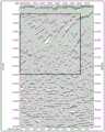
图1为本发明的一具体实施例中某工区最大偏移距5973m的叠加剖面的示意图;Fig. 1 is the schematic diagram of the stacked section of the maximum offset of a certain work area of 5973m in a specific embodiment of the present invention;
图2为本发明的一具体实施例中最大偏移距5973m图1的偏移剖面的示意图;Fig. 2 is a schematic diagram of the offset profile of Fig. 1 with a maximum offset distance of 5973m in a specific embodiment of the present invention;
图3为图1工区最大偏移距7000m的叠加剖面的示意图;Figure 3 is a schematic diagram of a superimposed section with a maximum offset distance of 7000m in the work area of Figure 1;
图4为最大偏移距7000m图3的偏移剖面的示意图;Figure 4 is a schematic diagram of the offset profile in Figure 3 with a maximum offset distance of 7000m;
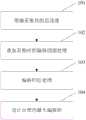
图5为本发明的监控地震采集资料观测系统最大偏移距设计合理性的方法的一具体实施例的流程图。Fig. 5 is a flow chart of a specific embodiment of the method for monitoring the design rationality of the maximum offset of the seismic acquisition data observation system of the present invention.
具体实施方式Detailed ways
应该指出,以下详细说明都是示例性的,旨在对本发明提供进一步的说明。除非另有指明,本文使用的所有技术和科学术语具有与本发明所属技术领域的普通技术人员通常理解的相同含义。It should be noted that the following detailed description is exemplary and intended to provide further explanation of the present invention. Unless defined otherwise, all technical and scientific terms used herein have the same meaning as commonly understood by one of ordinary skill in the art to which this invention belongs.
需要注意的是,这里所使用的术语仅是为了描述具体实施方式,而非意图限制根据本发明的示例性实施方式。如在这里所使用的,除非上下文另外明确指出,否则单数形式也意图包括复数形式,此外,还应当理解的是,当在本说明书中使用术语“包含”和/或“包括”时,其指明存在特征、步骤、操作和/或它们的组合。It should be noted that the terminology used here is only for describing specific embodiments, and is not intended to limit exemplary embodiments according to the present invention. As used herein, unless the context clearly dictates otherwise, the singular is intended to include the plural, and it should also be understood that when the terms "comprising" and/or "comprising" are used in this specification, they mean There are features, steps, operations and/or combinations thereof.
针对参数论证中利用叠加速度设计最大偏移距不合理的情况,本发明根据工区情况,将偏移处理结果考虑在内,设计了一套流程方法,获得最佳的设计最大偏移距。提出的最大偏移距设计方法,具有流程简洁明了,满足施工要求的特点。Aiming at the unreasonable situation of designing the maximum offset by superposition velocity in the parameter demonstration, the present invention designs a set of process methods according to the situation of the work area, taking the offset processing results into consideration, and obtains the best designed maximum offset. The proposed maximum offset design method has the characteristics of simple and clear process and meeting the construction requirements.
如图5所示,图5为本发明的监控地震采集资料观测系统最大偏移距设计合理性的方法的一具体实施例的流程图。As shown in FIG. 5 , FIG. 5 is a flow chart of a specific embodiment of the method for monitoring the design rationality of the maximum offset of the seismic acquisition data observation system of the present invention.
步骤101,对于某特定工区收集地震资料,根据地质任务明确采集目的层深度;
步骤102,对地震资料进行叠加及相应的偏移剖面处理;
步骤103,设置不同的偏移距范围分别进行相应的偏移归位处理;
步骤104,分析不同偏移距剖面目的层的显示及覆盖次数情况,以此为依据设计合理的最大偏移距。
如果不符合任务设计要求,需要不断加大偏移距,直到最大偏移距得到的偏移结果符合地质任务要求为止。If it does not meet the requirements of the mission design, it is necessary to continuously increase the offset until the migration result obtained by the maximum offset meets the requirements of the geological mission.
以下为应用本发明的几个具体实施例。The following are several specific embodiments of the application of the present invention.
实施例1Example 1
在应用本发明的一具体实施例1中,对于工区附近有测线通过的工区,本发明包括了以下步骤:In a
1)收集前期地震资料,明确采集任务目的层深度;1) Collect seismic data in the early stage, and specify the depth of the target layer of the acquisition task;
2)对前期地震资料数据进行叠加及相应的偏移剖面处理,对比叠加剖面与偏移剖面上目的层的精细程度及覆盖次数情况;2) Superimpose the previous seismic data and process the corresponding migration profile, and compare the fineness and coverage times of the target layer on the stacked profile and the migration profile;
3)设置不同的偏移距范围分别进行相应的偏移归位处理,首先根据标准:GB/T33583-2017,《陆上石油地震勘探资料采集技术规程》定义测试的最大与最小偏移距,测试的最大偏移距定义为:

其中公式中d为动校正拉伸百分比;k为速度分析精度;vRMS为均方根速度,单位为米每秒;fdom为目的层主频,单位为赫兹;t0为目的层双程反射时间,单位为秒。In the formula, d is the dynamic correction stretch percentage; k is the speed analysis accuracy; vRMS is the root mean square speed, the unit is m/s; fdom is the main frequency of the destination layer, the unit is Hz; t0 is the round trip of the destination layer Reflection time, in seconds.
4)分析不同偏移距剖面目的层的显示情况,设计合理的最大偏移距。4) Analyze the display of the target layer in different offset sections, and design a reasonable maximum offset.
实施例2Example 2
在应用本发明的一具体实施例2中,对于工区附近无测线通过的工区,本发明包括了以下步骤:In a specific embodiment 2 of applying the present invention, the present invention includes the following steps for the work area where no survey line passes near the work area:
1)收集周边的地层分布及地质构造情况,明确采集任务目的层深度;1) Collect the surrounding stratum distribution and geological structure, and clarify the depth of the target layer of the collection task;
2)对工区范围进行等比例缩放,根据周边地层分布及地质构造情况建立模型,进行正演模拟分析;2) Scale the scope of the work area in equal proportions, establish a model according to the surrounding stratum distribution and geological structure, and carry out forward modeling analysis;
3)对模拟放炮结果进行叠加及偏移归位处理,对比叠加剖面与偏移剖面上目的层的精细程度及覆盖次数情况;3) Perform superimposition and migration homing processing on the simulated blasting results, and compare the fineness and coverage times of the target layer on the stacked section and the migration section;
4)设置不同的偏移距范围分别进行相应的偏移归位处理,首先根据标准:GB/T33583-2017,《陆上石油地震勘探资料采集技术规程》定义测试的最大与最小偏移距,测试的最大偏移距定义为:

其中公式中d为动校正拉伸百分比;k为速度分析精度;vRMS为均方根速度,单位为米每秒;fdom为目的层主频,单位为赫兹;t0为目的层双程反射时间,单位为秒。In the formula, d is the dynamic correction stretch percentage; k is the speed analysis accuracy; vRMS is the root mean square speed, the unit is m/s; fdom is the main frequency of the destination layer, the unit is Hz; t0 is the round trip of the destination layer Reflection time, in seconds.
5)分析不同偏移距剖面目的层的显示情况,设计合理的最大偏移距。5) Analyze the display of the target layer in different offset sections, and design a reasonable maximum offset.
实施例3Example 3
在应用本发明的一具体实施例3中,该监控地震采集资料观测系统最大偏移距设计合理性的方法包括了以下步骤:In a specific embodiment 3 of the application of the present invention, the method for monitoring the rationality of the design of the maximum offset of the seismic acquisition data observation system includes the following steps:
1)对于某特定工区收集前期地震资料,明确采集任务目的层深度,本次实施例中高陡构造部位为目标层位之一,需要将该部位信息进行良好采集记录,该部位的采集记录时间在0.5-4.0s之间;1) For the collection of previous seismic data in a specific work area, the depth of the target layer of the acquisition task is specified. In this embodiment, the high and steep structural part is one of the target layers, and the information of this part needs to be well collected and recorded. The acquisition and recording time of this part is in Between 0.5-4.0s;
2)对前期地震资料进行叠加及相应的偏移剖面处理,本次实施例中叠加处理后显示该剖面,如图1所示,的高陡构造清晰,最大覆盖次数符合任务要求,之后对叠加剖面进行了偏移处理,如图2所示,偏移成像结果表明高陡构造下部显示不清,因此利用叠加剖面得到最大偏移距过小,需要增加最大偏移距;图1中目的层位高陡构造的采集记录时间为0.5s-4.0s,其层位显示清晰,覆盖次数达到满次要求,黑色框内为高陡构造位置;图2中目的层位高陡构造经偏移归位后,其采集记录时间2.2s以下的部位显示不清,说明最大偏移距设计不合理,黑色框内为高陡构造位置。2) Superimpose the previous seismic data and process the corresponding migration section. In this embodiment, the section is displayed after the superposition processing, as shown in Figure 1. The high and steep structure is clear, and the maximum coverage times meet the task requirements. Afterwards, the superposition The profile has been migrated, as shown in Figure 2, the migration imaging results show that the lower part of the high and steep structure is not clearly displayed, so the maximum offset obtained by stacking the profile is too small, and the maximum offset needs to be increased; the target layer in Figure 1 The acquisition and recording time of the high-steep structure is 0.5s-4.0s, its horizons are clearly displayed, and the coverage times meet the requirements of full times. The position of the high-steep structure is shown in the black frame; After positioning, the part whose acquisition and recording time is less than 2.2s is unclear, indicating that the design of the maximum offset is unreasonable, and the black frame is the position of the high and steep structure.
3)通过前期的道距、炮距等实际情况,设置最小的测试偏移距为4500m,最大的偏移距为8000m,整个测试在此范围内进行,本工区设置的间隔偏移距为50m,通过对最小偏移距不断增加间隔偏移距进行偏移处理,直到继续增大间隔,偏移后的成像效果不变为止;3) According to the actual conditions such as track distance and gun distance in the early stage, the minimum test offset distance is set to 4500m, and the maximum offset distance is 8000m. The entire test is carried out within this range, and the interval offset distance set in this work area is 50m. , by continuously increasing the interval offset for the minimum offset to perform offset processing until the interval continues to increase, and the imaging effect after migration remains unchanged;
4)分析不同偏移距剖面目的层的显示及覆盖次数情况,以此为依据设计合理的最大偏移距。在本次实施例中当最大偏移距增大至7000m后,无论是叠加剖面还是偏移剖面,高陡构造的位置显示精度及覆盖次数均达到了采集任务需求,因此选取此次采集的最大偏移距为7000m。4) Analyze the display and coverage times of the target layer in different offset sections, and design a reasonable maximum offset based on this. In this embodiment, when the maximum offset distance is increased to 7000m, the position display accuracy and coverage times of high and steep structures have met the requirements of the acquisition task whether it is a stacked section or an offset section, so the maximum The offset distance is 7000m.
图3为图1工区最大偏移距7000m的叠加剖面的示意图;图3中目的层位高陡构造的采集记录时间为0.5s-4.0s,其层位显示清晰,覆盖次数达到满次要求。黑色框内为高陡构造位置。Figure 3 is a schematic diagram of the superimposed section of the work area in Figure 1 with a maximum offset of 7000m; in Figure 3, the collection and recording time of the high-steep structure of the target horizon is 0.5s-4.0s, the horizons are clearly displayed, and the coverage times meet the full requirements. The high and steep structural positions are in the black frame.
图4为最大偏移距7000m图3的偏移剖面图,图4中目的层位高陡构造经偏移归位后,其采集记录时间0.5-4.0s,目的层各部位显示清晰,最大偏移距设计合理。黑色框内为高陡构造位置。Figure 4 is the migration profile of Figure 3 with a maximum offset distance of 7000m. Reasonable shift design. The high and steep structural positions are in the black frame.
最后应说明的是:以上所述仅为本发明的优选实施例而已,并不用于限制本发明,尽管参照前述实施例对本发明进行了详细的说明,对于本领域技术人员来说,其依然可以对前述实施例记载的技术方案进行修改,或者对其中部分技术特征进行等同替换。凡在本发明的精神和原则之内,所作的任何修改、等同替换、改进等,均应包含在本发明的保护范围之内。Finally, it should be noted that: the above is only a preferred embodiment of the present invention, and is not intended to limit the present invention. Although the present invention has been described in detail with reference to the foregoing embodiments, for those skilled in the art, it can still The technical solutions described in the foregoing embodiments are modified, or some of the technical features are equivalently replaced. Any modifications, equivalent replacements, improvements, etc. made within the spirit and principles of the present invention shall be included within the protection scope of the present invention.
除说明书所述的技术特征外,均为本专业技术人员的已知技术。Except for the technical features described in the instructions, all are known technologies by those skilled in the art.
Claims (8)
Translated fromChinese

Priority Applications (1)
| Application Number | Priority Date | Filing Date | Title |
|---|---|---|---|
| CN202111299631.4ACN116068636A (en) | 2021-11-04 | 2021-11-04 | Method for monitoring design rationality of maximum offset of seismic acquisition data observation system |
Applications Claiming Priority (1)
| Application Number | Priority Date | Filing Date | Title |
|---|---|---|---|
| CN202111299631.4ACN116068636A (en) | 2021-11-04 | 2021-11-04 | Method for monitoring design rationality of maximum offset of seismic acquisition data observation system |
Publications (1)
| Publication Number | Publication Date |
|---|---|
| CN116068636Atrue CN116068636A (en) | 2023-05-05 |
Family
ID=86175674
Family Applications (1)
| Application Number | Title | Priority Date | Filing Date |
|---|---|---|---|
| CN202111299631.4APendingCN116068636A (en) | 2021-11-04 | 2021-11-04 | Method for monitoring design rationality of maximum offset of seismic acquisition data observation system |
Country Status (1)
| Country | Link |
|---|---|
| CN (1) | CN116068636A (en) |
Citations (7)
| Publication number | Priority date | Publication date | Assignee | Title |
|---|---|---|---|---|
| US6665618B1 (en)* | 2002-08-14 | 2003-12-16 | Conocophillips Company | Seismic survey design technique |
| CN102645670A (en)* | 2011-02-22 | 2012-08-22 | 中国石油天然气集团公司 | Observation system optimization design method based on stack response analysis |
| CN104536041A (en)* | 2014-12-17 | 2015-04-22 | 中国石油天然气集团公司 | Optimization method of seismological observation system parameters |
| CN105093296A (en)* | 2015-06-30 | 2015-11-25 | 中国石油天然气集团公司 | Method and device for optimizing observation system |
| CN105824042A (en)* | 2015-01-08 | 2016-08-03 | 中石化石油工程地球物理有限公司胜利分公司 | Maximum longitudinal distance design method based on optimal lighting energy |
| US20170160410A1 (en)* | 2016-01-18 | 2017-06-08 | Changjiang Geophysical Exploration & Testing (Wuhan) Co., Ltd. | Seismic reflection data acquisition method adopting concentric circle equal offset |
| CN112255672A (en)* | 2020-09-24 | 2021-01-22 | 中国石油天然气股份有限公司 | Seismic data acquisition coverage frequency optimization method |
- 2021
- 2021-11-04CNCN202111299631.4Apatent/CN116068636A/enactivePending
Patent Citations (7)
| Publication number | Priority date | Publication date | Assignee | Title |
|---|---|---|---|---|
| US6665618B1 (en)* | 2002-08-14 | 2003-12-16 | Conocophillips Company | Seismic survey design technique |
| CN102645670A (en)* | 2011-02-22 | 2012-08-22 | 中国石油天然气集团公司 | Observation system optimization design method based on stack response analysis |
| CN104536041A (en)* | 2014-12-17 | 2015-04-22 | 中国石油天然气集团公司 | Optimization method of seismological observation system parameters |
| CN105824042A (en)* | 2015-01-08 | 2016-08-03 | 中石化石油工程地球物理有限公司胜利分公司 | Maximum longitudinal distance design method based on optimal lighting energy |
| CN105093296A (en)* | 2015-06-30 | 2015-11-25 | 中国石油天然气集团公司 | Method and device for optimizing observation system |
| US20170160410A1 (en)* | 2016-01-18 | 2017-06-08 | Changjiang Geophysical Exploration & Testing (Wuhan) Co., Ltd. | Seismic reflection data acquisition method adopting concentric circle equal offset |
| CN112255672A (en)* | 2020-09-24 | 2021-01-22 | 中国石油天然气股份有限公司 | Seismic data acquisition coverage frequency optimization method |
Non-Patent Citations (2)
| Title |
|---|
| 崔晓滨: "武威盆地地震采集技术研究", 中国优秀硕士学位论文全文数据库 工程科技I辑, no. 07, 15 July 2020 (2020-07-15), pages 9 - 16* |
| 陈红恩 等: "高精度三维地震勘探技术在青藏高原沙漠戈壁区煤田的应用", 中国煤田地质, 31 October 2007 (2007-10-31)* |
Similar Documents
| Publication | Publication Date | Title |
|---|---|---|
| CN108957549B (en) | Braided river sediment heterogeneous compact sandstone gas reservoir geological modeling method | |
| CN106855636B (en) | The prototype geological model Seismic forward method appeared based on carbonate reservoir | |
| CN112883564B (en) | Water body temperature prediction method and prediction system based on random forest | |
| CN104155701B (en) | A kind of multi-scale facture Forecasting Methodology utilizing Prestack seismic data and well information | |
| CN101315427A (en) | A method and system for processing seismic exploration data in complex areas | |
| CN111722284B (en) | Method for establishing speed depth model based on gather data | |
| CN103592682B (en) | Seismic wave field energy balancing method and processing device | |
| CN110954944A (en) | Fault trap oil-containing height earthquake prediction method | |
| CN107462924A (en) | A kind of absolute wave impedance inversion method independent of well-log information | |
| CN104090297A (en) | Reverse illumination method for optimizing earthquake collection observing system | |
| CN101852864B (en) | Method for processing mass seismic data by using surface consistent statistical spectrum analysis technology | |
| CN104142516A (en) | Method for predicting thickness of thin single sand bed | |
| CN101609163B (en) | Multi-scale seismic data joint imaging method based on fluctuation theory | |
| CN113534259A (en) | Vibroseis efficient acquisition real-time prestack time migration imaging method | |
| CN103605158A (en) | Determination method and device for maximum geophone offset | |
| CN103076630A (en) | Hydrocarbon detection method based on elastic impedance gradient | |
| CN116068636A (en) | Method for monitoring design rationality of maximum offset of seismic acquisition data observation system | |
| CN111025397A (en) | Method for obtaining depth domain velocity model by combining seismic data reflected wave and scattered wave | |
| Wang et al. | Enhancing subsurface seismic profiling with distributed acoustic sensing and optimization algorithms | |
| CN111665563A (en) | Pre-stack offset vertical resolution evaluation method based on focus analysis | |
| CN113835123B (en) | Seismic acquisition parameter analysis method based on geological target pre-stack migration imaging | |
| CN105259577B (en) | A kind of method and device for the angle information for determining bed boundary | |
| CN118210059A (en) | Reservoir fracture prediction method and system | |
| CN110568149B (en) | Fine and rapid quantitative simulation method for hydrocarbon generation and discharge history of sedimentary basin hydrocarbon source rock | |
| CN119758455B (en) | A method for quantitatively restoring paleowater depth based on foreset reflection |
Legal Events
| Date | Code | Title | Description |
|---|---|---|---|
| PB01 | Publication | ||
| PB01 | Publication | ||
| SE01 | Entry into force of request for substantive examination | ||
| SE01 | Entry into force of request for substantive examination | ||
| TA01 | Transfer of patent application right | Effective date of registration:20250528 Address after:100728 Beijing, Chaoyangmen, North Street, No. 22, No. Applicant after:SINOPEC Group Country or region after:China Applicant after:Sinopec Petroleum Engineering Technology Service Co.,Ltd. Applicant after:SINOPEC PETROLEUM ENGINEERING GEOPHYSICS Co.,Ltd. Applicant after:SHENGLI BRANCH OF SINOPEC PETROLEUM ENGINEERING GEOPHYSICS Co.,Ltd. Address before:100728 Beijing, Chaoyangmen, North Street, No. 22, No. Applicant before:SINOPEC Group Country or region before:China Applicant before:SINOPEC OILFIELD SERVICE Corp. Applicant before:SINOPEC PETROLEUM ENGINEERING GEOPHYSICS Co.,Ltd. Applicant before:SHENGLI BRANCH OF SINOPEC PETROLEUM ENGINEERING GEOPHYSICS Co.,Ltd. | |
| TA01 | Transfer of patent application right |