CN116059023A - Fixed head, delivery system and its inner tube mechanism, catheter assembly, and medical device - Google Patents
Fixed head, delivery system and its inner tube mechanism, catheter assembly, and medical deviceDownload PDFInfo
- Publication number
- CN116059023A CN116059023ACN202111302111.4ACN202111302111ACN116059023ACN 116059023 ACN116059023 ACN 116059023ACN 202111302111 ACN202111302111 ACN 202111302111ACN 116059023 ACN116059023 ACN 116059023A
- Authority
- CN
- China
- Prior art keywords
- fixing head
- medical implant
- threading
- wire
- hole
- Prior art date
- Legal status (The legal status is an assumption and is not a legal conclusion. Google has not performed a legal analysis and makes no representation as to the accuracy of the status listed.)
- Pending
Links
Images


Classifications
- A—HUMAN NECESSITIES
- A61—MEDICAL OR VETERINARY SCIENCE; HYGIENE
- A61F—FILTERS IMPLANTABLE INTO BLOOD VESSELS; PROSTHESES; DEVICES PROVIDING PATENCY TO, OR PREVENTING COLLAPSING OF, TUBULAR STRUCTURES OF THE BODY, e.g. STENTS; ORTHOPAEDIC, NURSING OR CONTRACEPTIVE DEVICES; FOMENTATION; TREATMENT OR PROTECTION OF EYES OR EARS; BANDAGES, DRESSINGS OR ABSORBENT PADS; FIRST-AID KITS
- A61F2/00—Filters implantable into blood vessels; Prostheses, i.e. artificial substitutes or replacements for parts of the body; Appliances for connecting them with the body; Devices providing patency to, or preventing collapsing of, tubular structures of the body, e.g. stents
- A61F2/95—Instruments specially adapted for placement or removal of stents or stent-grafts
- A61F2/962—Instruments specially adapted for placement or removal of stents or stent-grafts having an outer sleeve
- A61F2/966—Instruments specially adapted for placement or removal of stents or stent-grafts having an outer sleeve with relative longitudinal movement between outer sleeve and prosthesis, e.g. using a push rod
Landscapes
- Health & Medical Sciences (AREA)
- Engineering & Computer Science (AREA)
- Biomedical Technology (AREA)
- Cardiology (AREA)
- Oral & Maxillofacial Surgery (AREA)
- Transplantation (AREA)
- Heart & Thoracic Surgery (AREA)
- Vascular Medicine (AREA)
- Life Sciences & Earth Sciences (AREA)
- Animal Behavior & Ethology (AREA)
- General Health & Medical Sciences (AREA)
- Public Health (AREA)
- Veterinary Medicine (AREA)
- Media Introduction/Drainage Providing Device (AREA)
Abstract
Translated fromChinese
Description
Translated fromChinese技术领域technical field
本发明涉及医疗器械技术领域,具体涉及一种固定头、输送系统及其内管机构、导管组件、及医用装置。The invention relates to the technical field of medical devices, in particular to a fixed head, a delivery system and its inner tube mechanism, a catheter assembly, and a medical device.
背景技术Background technique
医用植入物,例如自膨式支架、人工瓣膜等,在装载与释放的过程中需要具有特定的结构以通过形状契合或丝线等方式与输送器的对应结构进行连接,以保持医用植入物相对于解剖结构的位置,提升释放位置的精度,同时减小对组织的损伤。Medical implants, such as self-expanding stents, artificial valves, etc., need to have a specific structure during the loading and release process to connect with the corresponding structure of the conveyor through shape fit or silk, so as to maintain the medical implant Improves the precision of the release location relative to the location of the anatomy while reducing tissue damage.
其中,利用丝线使医用植入物与输送器进行连接的方式中,当医用植入物被输送至预定位置后,通过操控丝线来控制医用植入物的释放。现有技术中,在操控丝线的过程中,丝线与输送器的部分结构之间存在较大的摩擦力,导致控制力产生较大的损耗,降低医用植入物释放过程中的稳定性,增大了手术风险。Wherein, in the method of connecting the medical implant with the transporter by using a wire, after the medical implant is delivered to a predetermined position, the release of the medical implant is controlled by manipulating the wire. In the prior art, in the process of manipulating the wire, there is a large friction between the wire and the partial structure of the conveyor, which leads to a large loss of control force, reduces the stability of the medical implant release process, and increases the increased surgical risk.
发明内容Contents of the invention
本发明的目的在于提供一种固定头、输送系统及其内管机构、导管组件、及医用装置,旨在提高线控释放过程中的稳定性,提高手术安全。The purpose of the present invention is to provide a fixed head, a delivery system and its inner tube mechanism, a catheter assembly, and a medical device, aiming at improving the stability during the wire-controlled release process and improving the operation safety.
为实现上述目的,本发明提供了一种固定头,所述固定头上形成有穿线通道,所述穿线通道的部分表面形成为平滑的导向面,所述导向面用于在丝线穿过所述穿线通道时支撑所述丝线,并使所述丝线的延伸方向发生偏转。In order to achieve the above object, the present invention provides a fixing head, on which a threading channel is formed, and part of the surface of the threading channel is formed as a smooth guide surface, and the guide surface is used for thread passing through the The thread is supported when passing through the channel, and the extending direction of the thread is deflected.
可选地,所述导向面包括沿近端向远端依次平滑地连接的第一子导向面、第二子导向面和第三子导向面,其中,所述第一子导向面和所述第三子导向面的轴线均为直线,所述第一子导向面的轴线与所述第三子导向面的轴线所形成的夹角的角度为45°~135°,所述第二子导向面的轴线为弧线。Optionally, the guiding surface includes a first sub-guiding surface, a second sub-guiding surface, and a third sub-guiding surface that are smoothly connected sequentially from the proximal end to the distal end, wherein the first sub-guiding surface and the The axes of the third sub-guiding surface are all straight lines, the angle formed by the axis of the first sub-guiding surface and the axis of the third sub-guiding surface is 45°~135°, and the angle of the second sub-guiding surface The axes of the faces are arcs.
可选地,所述穿线通道包括穿线孔,所述穿线孔包括第一孔段,所述第一孔段的部分孔壁构成所述第一子导向面。Optionally, the threading channel includes a threading hole, the threading hole includes a first hole segment, and part of the hole wall of the first hole segment constitutes the first sub-guiding surface.
可选地,所述穿线孔还包括第二孔段和第三孔段;所述第二孔段的近端与所述第一孔段的远端连通,所述第二孔段的部分孔壁构成所述第二子导向面,所述第三孔段的近端与所述第二孔段的远端连通,所述第三孔段的部分孔壁构成所述第三子导向面。Optionally, the threading hole further includes a second hole segment and a third hole segment; the proximal end of the second hole segment communicates with the distal end of the first hole segment, and part of the holes in the second hole segment The wall constitutes the second sub-guiding surface, the proximal end of the third hole section communicates with the distal end of the second hole section, and part of the hole wall of the third hole section constitutes the third sub-guiding surface.
可选地,所述固定头包括轴向连接的近端部分和远端部分,所述近端部分的横截面的面积沿近端向远端的方向逐渐增大。Optionally, the fixing head includes a proximal part and a distal part axially connected, and the cross-sectional area of the proximal part gradually increases along the direction from the proximal end to the distal end.
可选地,所述固定头包括固定头本体和转动件,所述固定头本体上形成有沿其轴向贯通地延伸的穿线槽,所述转动件可转动地连接于所述穿线槽的槽壁上,并与所述穿线槽的至少部分槽壁围合成所述穿线通道;所述转动件具有圆周面,且所述圆周面的一部分区域构成所述导向面。Optionally, the fixed head includes a fixed head body and a rotating member, the fixed head body is formed with a threading groove extending through the axial direction thereof, and the rotating member is rotatably connected to the groove of the threading groove On the wall, and at least part of the groove wall of the threading groove forms the threading channel; the rotating member has a peripheral surface, and a part of the peripheral surface constitutes the guiding surface.
可选地,所述穿线槽沿所述固定头本体的径向延伸,并在所述固定头本体的边缘处开口,所述转动件的所述圆周面背离所述开口的一侧至少部分地形成所述导线面。Optionally, the threading groove extends radially of the fixed head body and opens at an edge of the fixed head body, and the side of the circumferential surface of the rotating member facing away from the opening is at least partially forming the wire surface.
可选地,所述转动件的圆周面上形成有沿所述转动件的周向延伸一圈的定位槽,所述定位槽的部分槽壁构成所述导向面。Optionally, a positioning groove extending one circle along the circumferential direction of the rotating member is formed on the circumferential surface of the rotating member, and a part of the groove wall of the positioning groove constitutes the guiding surface.
可选地,在所述转动件的纵截面上,所述定位槽为弧形。Optionally, on the longitudinal section of the rotating member, the positioning groove is arc-shaped.
可选地,所述固定头还包括底座,所述底座连接于所述固定头本体的近端端面上,所述底座上设有与所述穿线通道相贯通的导入通道,且所述底座的横截面的面积沿近端向远端的方向增大。Optionally, the fixed head further includes a base, the base is connected to the proximal end surface of the fixed head body, the base is provided with an introduction channel that communicates with the threading channel, and the base The area of the cross-section increases in the direction from the proximal end to the distal end.
可选地,所述固定头上还设有安装通孔,以使所述固定头能够套装至目标管体上;所述穿线通道的数量为至少一个,当所述穿线通道的数量为多个时,多个所述穿线通道环绕所述安装通孔间隔地布置。Optionally, the fixing head is also provided with an installation through hole, so that the fixing head can be fitted onto the target tube body; the number of the threading channel is at least one, when the number of the threading channel is multiple When, a plurality of the threading channels are arranged at intervals around the installation through hole.
可选地,所述导向面的表面粗糙度Ra小于或等于0.2。Optionally, the surface roughness Ra of the guide surface is less than or equal to 0.2.
为实现上述目的,本发明还提供了一种用于输送系统的内管机构,包括内管体和如前任一项所述的固定头,所述固定头设置于所述内管体的远端外表面上。To achieve the above object, the present invention also provides an inner tube mechanism for a delivery system, comprising an inner tube body and the fixing head as described in any one of the preceding items, and the fixing head is arranged at the distal end of the inner tube body on the outside.
为实现上述目的,本发明还提供了一种用于输送系统的导管组件,包括外管和如前所述的输送系统的内管机构,所述外管套装在所述内管机构的外部,并被配置为能够与所述内管机构产生轴向相对运动。To achieve the above object, the present invention also provides a catheter assembly for a delivery system, comprising an outer tube and the aforementioned inner tube mechanism of the delivery system, the outer tube is sleeved on the outside of the inner tube mechanism, And it is configured to be able to produce axial relative movement with the inner tube mechanism.
为实现上述目的,本发明还提供了一种输送系统,包括输送器和丝线,所述输送器包括手柄和如前所述的输送系统的导管组件,所述导管组件用于装载一医用植入物,所述手柄连接于所述导管组件的近端,并用于控制所述外管相对于所述内管机构产生轴向相对运动,所述丝线的近端与所述输送器连接,所述丝线的远端用于穿过所述穿线通道,并与所述医用植入物及所述输送器可分离地连接。To achieve the above object, the present invention also provides a delivery system, including a delivery device and a wire, the delivery device includes a handle and the catheter assembly of the delivery system as described above, and the catheter assembly is used to load a medical implant The handle is connected to the proximal end of the catheter assembly, and is used to control the relative axial movement of the outer tube relative to the inner tube mechanism, the proximal end of the wire is connected to the conveyor, the The distal end of the wire is used to pass through the threading channel, and is detachably connected with the medical implant and the delivery device.
为实现上述目的,本发明还提供了一种医用装置,包括医用植入物和如前所述的输送系统,所述医用植入物装载于所述导管组件中;所述丝线的远端穿过所述穿线通道,并与所述医用植入物及所述输送器可分离地连接。In order to achieve the above object, the present invention also provides a medical device, including a medical implant and the aforementioned delivery system, the medical implant is loaded in the catheter assembly; the distal end of the silk thread passes through passing through the threading channel, and detachably connected with the medical implant and the conveyer.
可选地,所述固定头的数量为至少一个,所述固定头设置于所述医用植入物的近端侧和/或远端侧;Optionally, the number of the fixing head is at least one, and the fixing head is arranged on the proximal side and/or the distal side of the medical implant;
当所述医用植入物处于压握状态,且所述固定头位于所述医用植入物的近端侧时,所述导向面使所述丝线的延伸方向偏转90°~135°;或者,当所述医用植入物处于压握态,且所述固定头位于所述医用植入物的远端侧时,所述导向面使所述丝线的延伸方向偏转45°~90°。When the medical implant is in a crimped state and the fixing head is located at the proximal side of the medical implant, the guide surface deflects the extending direction of the wire by 90°-135°; or, When the medical implant is in a crimped state and the fixing head is located at the distal side of the medical implant, the guiding surface deflects the extension direction of the wire by 45°-90°.
与现有技术相比,本发明的固定头、输送系统及其内管机构、导管组件及医用装置具有如下优点:Compared with the prior art, the fixed head, delivery system and its inner tube mechanism, catheter assembly and medical device of the present invention have the following advantages:
前述的固定头上形成有穿线通道,所述穿线通道的至少部分表面形成为平滑的导线面,所述导向面用于在一丝线穿过所述穿线通道时支撑所述丝线,并使所述丝线的延伸方向发生偏转。所述固定头用于设置在一输送系统上,所述输送系统包括输送器和丝线,所述输送器包括导管组件,所述导管组件用于装载医用植入物,且所述导管组件包括内管体和设置于其上的所述固定头,所述丝线的远端穿过所述固定头上的所述穿线通道,并与所述医用植入物及所述输送器可分离地连接,在平滑的所述导向面的作用下,所述丝线的远端在穿过所述穿线通道时能够平滑地进行方向偏转,从而使用者在通过操控所述丝线来释放所述医用植入物时,所述丝线与所述固定头之间的摩擦力较小,从而减少控制力的损失,提高医用植入物释放过程的稳定性,进而提高手术安全性。A threading channel is formed on the aforementioned fixing head, at least part of the surface of the threading channel is formed as a smooth wire surface, and the guide surface is used to support the thread when the thread passes through the threading channel, and make the thread The extension direction of the wire is deflected. The fixing head is used to be arranged on a delivery system, the delivery system includes a delivery device and a wire, the delivery device includes a catheter assembly for loading a medical implant, and the catheter assembly includes an inner a tube body and the fixing head arranged thereon, the distal end of the wire passes through the threading channel on the fixing head, and is detachably connected with the medical implant and the conveyor, Under the action of the smooth guide surface, the distal end of the wire can smoothly deflect in direction when passing through the threading channel, so that when the user releases the medical implant by manipulating the wire , the frictional force between the silk thread and the fixing head is small, thereby reducing the loss of control force, improving the stability of the release process of the medical implant, and further improving the safety of the operation.
进一步地,前述的医用装置包括植入物和所述输送系统,且所述输送系统包括至少一个所述固定头,所述固定头设置于所述医用植入物的近端侧和/或远端侧;当所述医用植入物处于压握状态,且所述固定头位于所述医用植入物的近端侧时,所述导向面使所述丝线的延伸方向偏转90°~135°;或者,当所述医用植入物处于压握态,且所述固定头位于所述医用植入物的远端侧时,所述导向面使所述丝线的延伸方向偏转45°~90°。这样做是为了使所述医用植入物被径向压缩时,可以与所述固定头在轴向上的不重合,降低所述医用装置的柔软度,提高医用装置的过弯性能,有利于所述输送系统将所述医用植入物输送至预定位置。Further, the aforementioned medical device includes an implant and the delivery system, and the delivery system includes at least one fixing head, and the fixing head is arranged on the proximal side and/or the distal side of the medical implant. End side; when the medical implant is in a crimped state and the fixing head is located at the proximal side of the medical implant, the guide surface deflects the extending direction of the wire by 90° to 135° or, when the medical implant is in a crimped state and the fixing head is located at the distal side of the medical implant, the guiding surface deflects the extending direction of the wire by 45° to 90° . This is done so that when the medical implant is radially compressed, it can be misaligned with the fixed head in the axial direction, reducing the flexibility of the medical device and improving the bending performance of the medical device, which is beneficial to The delivery system delivers the medical implant to a predetermined location.
附图说明Description of drawings
附图用于更好地理解本发明,不构成对本发明的不当限定。其中:The accompanying drawings are used to better understand the present invention, and do not constitute improper limitations to the present invention. in:
图1是本发明根据一实施例所提供的输送系统的整体结构示意图;Fig. 1 is a schematic diagram of the overall structure of a delivery system provided by the present invention according to an embodiment;
图2是本发明根据一实施例所提供的输送系统的内管机构的结构示意图;Fig. 2 is a schematic structural view of the inner tube mechanism of the delivery system according to an embodiment of the present invention;
图3是本发明根据一实施例所提供的输送系统的固定头的结构示意图;Fig. 3 is a schematic structural view of the fixed head of the delivery system provided according to an embodiment of the present invention;
图4是本发明根据一实施例所提供的输送系统的固定头的A-A剖视图;Fig. 4 is an A-A cross-sectional view of the fixing head of the delivery system provided according to an embodiment of the present invention;
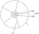
图5是本发明根据一实施例所提供的输送系统在装载医用植入物时,丝线与医用植入物的连接关系示意图,图示中丝线以辐射的形式与医用植入物连接;Fig. 5 is a schematic diagram of the connection relationship between the wire and the medical implant when the delivery system according to an embodiment of the present invention is loaded with the medical implant, in which the wire is connected to the medical implant in the form of radiation;
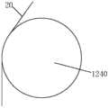
图6是本发明根据一实施例所提供的输送系统在装载医用植入物时,丝线与医用植入物的连接关系示意图,图示中,丝线在周向上环绕医用植入物;Fig. 6 is a schematic diagram of the connection relationship between the wire and the medical implant when the delivery system according to an embodiment of the present invention is loaded with the medical implant. In the illustration, the wire surrounds the medical implant in the circumferential direction;
图7是本发明根据另一实施例所提供的输送系统的固定头的结构示意图,图示中的固定头不包括底座;Fig. 7 is a schematic structural view of a fixing head of a delivery system according to another embodiment of the present invention, and the fixing head in the illustration does not include a base;
图8是本发明根据另一实施例所提供的输送系统的固定头的结构示意图,图示中的固定头包括底座;Fig. 8 is a structural schematic diagram of a fixing head of a delivery system according to another embodiment of the present invention, the fixing head in the illustration includes a base;
图9是本发明根据另一实施例所提供的输送系统的固定头的结构示意图,图9与图8的观察方位不同;Fig. 9 is a schematic structural view of a fixed head of a delivery system according to another embodiment of the present invention, and Fig. 9 is viewed in a different direction from Fig. 8;
图10是本发明根据另一实施例所提供的输送系统的丝线在穿过固定头上的穿线通道时其延伸方向发生偏转的示意图;Fig. 10 is a schematic diagram of the deflection of the extending direction of the thread of the delivery system according to another embodiment of the present invention when passing through the threading channel on the fixing head;
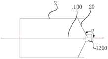
图11是本发明根据一实施例所提供的医用装置的局部结构示意图,图中医用植入物处于压握状态,且医用装置包括一个固定头,该固定头设置于医用植入物的远端侧;Fig. 11 is a schematic diagram of a partial structure of a medical device according to an embodiment of the present invention, in which the medical implant is in a crimped state, and the medical device includes a fixing head, which is arranged at the distal end of the medical implant side;
图12是图11所示的医用装置中,医用支架扩张时的示意图;Fig. 12 is a schematic diagram of the expansion of the medical stent in the medical device shown in Fig. 11;
图13是发明根据一实施例所提供的医用装置的局部结构示意图,图中医用植入物处于压握状态,且医用装置包括两个固定头,两个固定头分别设置于医用植入物的近端侧和远端侧;Fig. 13 is a schematic diagram of a partial structure of a medical device according to an embodiment of the invention. In the figure, the medical implant is in a crimped state, and the medical device includes two fixing heads, which are respectively arranged on the sides of the medical implant. proximal side and distal side;
图14是本发明根据一实施例所提供的医用装置的局部结构示意图,图中医用装置处于压握状态,且医用装置包括一个固定头,一个固定头设置于医用植入物的内部,且丝线位于固定头与医用植入物之间的部分与输送系统的轴线所形成的夹角为90°;Fig. 14 is a schematic diagram of a partial structure of a medical device according to an embodiment of the present invention. In the figure, the medical device is in a crimped state, and the medical device includes a fixing head, and a fixing head is arranged inside the medical implant, and the silk thread The angle formed by the part between the fixing head and the medical implant and the axis of the delivery system is 90°;
图15是本发明根据实施例所提供的医用装置的局部结构示意图,图中医用装置处于压握状态,且医用装置包括一个固定头,一个固定头设置于医用植入物的内部,且丝线位于固定头与医用植入物之间的部分与输送系统的轴线所形成的夹角小于90°。Fig. 15 is a schematic diagram of a partial structure of a medical device according to an embodiment of the present invention. In the figure, the medical device is in a crimped state, and the medical device includes a fixing head, and a fixing head is arranged inside the medical implant, and the wire is located The angle formed between the fixing head and the medical implant and the axis of the delivery system is less than 90°.
[附图标记说明如下]:[the reference signs are explained as follows]:
1-输送系统,100-导管组件,1000-内管机构,1100-内管体,1200-固定头,1200a-近端节段,1200b-第二节段,1210-穿线通道,1201-导向面,1201a-第一子导向面,1201b-第二子导向面,1201c-第三子导向面,1211-第一孔段,1212-第二孔段,1213-第三孔段,1220-安装通孔,1230-固定头本体,1231-穿线槽,1240-转动件,1241-定位槽,1250-底座,1251-导入通道,2000-外管,200-手柄,20-丝线,2-医用植入物。1-delivery system, 100-catheter assembly, 1000-inner tube mechanism, 1100-inner tube body, 1200-fixing head, 1200a-proximal segment, 1200b-second segment, 1210-threading channel, 1201-guiding surface , 1201a-first sub-guiding surface, 1201b-second sub-guiding surface, 1201c-third sub-guiding surface, 1211-first hole section, 1212-second hole section, 1213-third hole section, 1220-installation pass Hole, 1230-fixed head body, 1231-threading groove, 1240-rotating member, 1241-positioning groove, 1250-base, 1251-introduction channel, 2000-outer tube, 200-handle, 20-silk thread, 2-medical implant thing.
具体实施方式Detailed ways
以下通过特定的具体实例说明本发明的实施方式,本领域技术人员可由本说明书所揭露的内容轻易地了解本发明的其他优点与功效。本发明还可以通过另外不同的具体实施方式加以实施或应用,本说明书中的各项细节也可以基于不同观点与应用,在没有背离本发明的精神下进行各种修饰或改变。需要说明的是,本实施例中所提供的图示仅以示意方式说明本发明的基本构想,遂图式中仅显示与本发明中有关的组件而非按照实际实施时的组件数目、形状及尺寸绘制,其实际实施时各组件的型态、数量及比例可为一种随意的改变,且其组件布局型态也可能更为复杂。Embodiments of the present invention are described below through specific examples, and those skilled in the art can easily understand other advantages and effects of the present invention from the content disclosed in this specification. The present invention can also be implemented or applied through other different specific implementation modes, and various modifications or changes can be made to the details in this specification based on different viewpoints and applications without departing from the spirit of the present invention. It should be noted that the diagrams provided in this embodiment are only schematically illustrating the basic idea of the present invention, and only the components related to the present invention are shown in the diagrams rather than the number, shape and shape of the components in actual implementation. Dimensional drawing, the type, quantity and proportion of each component can be changed arbitrarily during actual implementation, and the component layout type may also be more complicated.
另外,以下说明内容的各个实施例分别具有一或多个技术特征,然此并不意味着使用本发明者必需同时实施任一实施例中的所有技术特征,或仅能分开实施不同实施例中的一部或全部技术特征。换句话说,在实施为可能的前提下,本领域技术人员可依据本发明的公开内容,并视设计规范或实作需求,选择性地实施任一实施例中部分或全部的技术特征,或者选择性地实施多个实施例中部分或全部的技术特征的组合,借此增加本发明实施时的弹性。In addition, each embodiment of the content described below has one or more technical features, but this does not mean that the inventor must implement all the technical features in any embodiment at the same time, or can only implement different embodiments separately. Some or all of the technical features. In other words, on the premise that the implementation is possible, those skilled in the art can selectively implement some or all of the technical features in any embodiment according to the disclosure of the present invention and depending on design specifications or implementation requirements, or Selectively implement a combination of some or all of the technical features in multiple embodiments, thereby increasing the flexibility of the implementation of the present invention.
如在本说明书中所使用的,单数形式“一”、“一个”以及“该”包括复数对象,复数形式“多个”包括两个以上的对象,除非内容另外明确指出外。如在本说明书中所使用的,术语“或”通常是以包括“和/或”的含义而进行使用的,除非内容另外明确指出外,以及术语“安装”、“相连”、“连接”应做广义理解,例如,可以是固定连接,也可以是可拆卸连接,或一体地连接。可以是机械连接,也可以是电连接。可以是直接相连,也可以通过中间媒介间接相连,可以是两个元件内部的连通或两个元件的相互作用关系。对于本领域的普通技术人员而言,可以根据具体情况理解上述术语在本发明中的具体含义。As used in this specification, the singular forms "a", "an" and "the" include plural objects, and the plural form "a plurality" includes two or more objects, unless the content clearly states otherwise. As used in this specification, the term "or" is generally used in the sense including "and/or", unless the content clearly indicates otherwise, and the terms "install", "connect" and "connect" should be To understand it in a broad sense, for example, it can be a fixed connection, a detachable connection, or an integral connection. It can be a mechanical connection or an electrical connection. It can be directly connected or indirectly connected through an intermediary, and it can be the internal communication of two elements or the interaction relationship between two elements. Those of ordinary skill in the art can understand the specific meanings of the above terms in the present invention according to specific situations.
在本文中,术语“近端”、“远端”是从使用该医疗器械的医生角度来看相对于彼此的元件或动作的相对方位、相对位置、方向,尽管“近端”、“远端”并非是限制性的,但是“近端”通常指该医疗设备在正常操作过程中靠近医生的一端,而“远端”通常是指首先进入患者体内的一端。In this context, the terms "proximal", "distal" refer to the relative orientation, relative position, direction of elements or actions relative to each other from the perspective of a doctor using the medical device, although "proximal", "distal ” is not limiting, but “proximal” generally refers to the end of the medical device that is closest to the practitioner during normal operation, and “distal” generally refers to the end that enters the patient first.
为使本发明的目的、优点和特征更加清楚,以下结合附图对本发明作进一步详细说明。需说明的是,附图均采用非常简化的形式且均使用非精准的比例,仅用以方便、明晰地辅助说明本发明实施例的目的。附图中相同或相似的附图标记代表相同或相似的部件。In order to make the purpose, advantages and features of the present invention clearer, the present invention will be further described in detail below in conjunction with the accompanying drawings. It should be noted that all the drawings are in very simplified form and use inaccurate scales, and are only used to facilitate and clearly assist the purpose of illustrating the embodiments of the present invention. The same or similar reference numerals in the drawings represent the same or similar components.
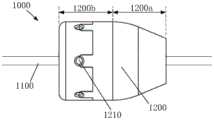
图1示出了本发明一实施例所提供的输送系统1的整体结构示意图,图2是所述输送系统1的内管机构1000的结构示意图,图3是所述内管机构1000上的固定头1200的结构示意图,图4是所述固定头1200的A-A剖视图。Fig. 1 shows a schematic diagram of the overall structure of the delivery system 1 provided by an embodiment of the present invention, Fig. 2 is a schematic diagram of the structure of the
请参考图1至图4,所述输送系统包括输送器(图中未标注)和丝线20(图1至图3中未示出,请参见图6及图7中所标注),所述丝线20的近端与所述输送器连接。所述输送器包括导管组件100和手柄200,所述导管组件100包括内管机构1000和外管2000,所述外管2000套装在所述内管机构1000的外部,并被配置为能够与所述内管机构1000之间产生轴向相对移动。所述手柄200连接于所述导管组件100的近端,并被配置用于控制所述内管机构1000与所述外管2000之间产生轴向相对移动。所述内管机构1000具体包括内管体1100和至少一个固定头1200,所述固定头1200设置在所述内管体1100的远端外表面上,当所述固定头1200的数量为两个以上时,两个以上的所述固定头1200沿轴向间隔地设置在所述内管体1100上。所述固定头1200上形成有穿线通道1210,所述穿线通道1210的部分表面形成为平滑的导向面1201,所述导向面1201用于在所述丝线20穿过所述穿线通道1210时对所述丝线20提供支撑力,并使所述丝线20的延伸方向发生偏转。这里,“平滑”的含义是指所述导向面1201上没有尖锐的棱边,也就是说,所述导向面1201为一连续的曲面,或者所述导向面1201包括多个不同的面,多个不同的面可以是平面也可以是曲面,且多个不同的面之间平滑过渡地连接。Please refer to FIGS. 1 to 4, the conveying system includes a conveyor (not marked in the figure) and a wire 20 (not shown in FIGS. 1 to 3, please refer to the marking in FIGS. 6 and 7), the wire The proximal end of 20 is connected to the conveyor. The delivery device includes a
所述输送系统1用于装载一医用植入物2(图1至图3中未示出,请参见图5及图6中所标注),并用于将所述医用植入物2输送且释放至患者体内的预定位置处。所述医用植入物2包括但不限于医用支架、人工瓣膜等。The delivery system 1 is used to load a medical implant 2 (not shown in FIGS. 1 to 3 , please refer to the labels in FIGS. 5 and 6 ), and is used to deliver and release the
装载所述医用植入物2时,首先使所述内管机构1000的远端伸出所述外管2000,然后将所述医用植入物2套设在所述内管体1100的远端外表面,所述固定头1200可以位于所述医用植入物2的内侧,也可以位于所述医用植入物2的近端侧和/或远端侧。所述医用植入物2上还设有接合件(图中未示出),所述接合件例如是连接线圈或连接孔。接着,使所述丝线20沿所述输送器的轴向延伸,并使所述丝线20的远端依次穿过所述穿线通道1210和处于扩张状态的所述医用植入物2上的所述接合件,再与所述输送器连接,以将所述医用植入物2束缚在所述内管机构1000上。接着,收紧所述丝线20并径向压缩所述医用植入物2,以使得所述医用植入物2处于压握状态,此时,所述丝线20贴靠在至少部分所述导线面1201上,并使得所述丝线20的延伸方向发生偏转,所述丝线20的偏转角度可以为45°~135°。这里“所述丝线20的偏转角度为45°~135°”是指,所述丝线20在所述穿线通道1210的出口处的延伸方向与所述输送器的轴线所形成的夹角α(如图11至图15所标注)的角度为45°~135°,也即,所述丝线20的位于所述固定头1200与所述医用植入物2之间的部分与所述输送器的轴线所形成的夹角α的角度为45°~135°。最后,使用者通过所述手柄200控制所述外管2000与所述内管机构1000产生轴向相对移动,以使得所述外管2000包裹所述医用植入物2。When loading the
释放所述医用植入物2时,使用者通过所述手柄200控制所述内管机构1000与所述外管2000产生轴向相对移动,以使得所述内管机构1000的远端及其上的医用植入物2从所述外管2000中伸出。然后使用者向所述丝线20施加控制力,以放松所述丝线20,并使得所述医用植入物2沿所述内管机构1000的径向扩张,直至所述医用植入物2与预定位置贴靠,最后根据所述丝线20的远端与所述输送器的连接方式进行相应操作以使所述丝线20的远端从所述医用植入物2上的接合件(例如连接线圈)穿出,解除所述丝线20的远端与所述医用植入物2的连接,完成所述医用植入物2的释放。可以理解的是,在所述医用植入物2的径向扩张的过程中,若所述医用植入物2定位不准确,使用者还可以通过向所述丝线20施加控制力,以重新收紧所述丝线20来重新压缩所述医用植入物2,然后控制所述外管2000相对于所述内管机构1000沿近端向远端的方向移动,并重新包裹所述医用植入物2(该过程可以被称之为回收过程)。之后,使用者能够调整所述医用植入物2的位置,并再次进行释放。需要说明的是,本发明实施例对所述丝线20的远端与输送器的连接方式不做限定,只要通过相应操作能够使得所述丝线20的远端从所述医用植入物2上的接合件穿出即可,具体的连接方式可参考现有技术。When the
这里,使用者通过所述手柄200控制所述外管2000与所述内管机构1000产生轴向相对移动的具体移动方式,与所述导管组件100的具体结构及其与所述手柄200的连接方式有关。Here, the user uses the
详细来说,在一些实现方式中,所述手柄200上设有外管控制机构和/或内管控制机构,且所述外管2000是一根具有较大长度的管体,装配所述导管组件100与所述手柄200时,所述外管2000的近端与所述外管控制机构连接,所述内管机构1000的所述内管体1100的近端与所述内管控制机构连接(如图1所示)。如此,装载所述医用植入物2时,可控制所述内管机构1000保持静止,通过所述手柄200上的所述外管控制机构控制所述外管沿近端向远端移动;或者控制所述外管1000保持静止,通过所述内管控制机构控制所述内管机构1000沿远端向近端的方向移动。在释放所述医用植入物2时,可控制所述内管机构1000保持静止,并控制所述外管2000沿远端向近端的方向移动;或者控制所述外管2000保持静止,并控制所述内管体1000沿近端向远端的方向移动。In detail, in some implementations, the
在另一些实现方式中,所述外管的长度较短,其可以仅比所述医用植入物的长度略长,在此,所述导管组件还包括顶管、导引连接头以及推送管,所述顶管套设在所述内管机构的外部,并设置于所述外管的近端侧,所述顶管的远端用于与所述外管的近端抵接。所述导引连接头连接于所述外管的远端,并位于所述内管体的远端。所述推送管至少部分地设置于所述内管体的管腔中,且所述推送管的远端与所述导引连接头连接,所述推送管还被配置为能够相对于所述内管体做轴向移动,以带动所述外管相对于所述内管机构做轴向移动(图中未示出)。所述手柄上设有一推送控制机构,装配所述导管组件与所述手柄时,所述内管体的近端和所述顶管的近端均与所述手柄连接,且所述内管体和所述顶管保持相对静止,所述推送管的近端与所述推送控制机构连接,也即利用所述推送控制机构控制所述推送管沿所述内管体的轴向移动。在装载所述医用植入物且所述医用植入物被压缩后,控制所述推送管沿远端向近端的方向移动,以带动所述外管沿远端向近端的方向移动,直至所述外管包裹所述医用植入物,且所述外管的近端抵靠在所述顶管的远端。在释放所述医用植入物时,控制所述推送管沿近端向远端的方向移动,以带动所述外管沿近端向远端的方向移动即可。In other implementations, the length of the outer tube is relatively short, and it may be only slightly longer than the length of the medical implant. Here, the catheter assembly also includes a push tube, a guiding connector, and a push tube , the jacking tube is sheathed on the outside of the inner tube mechanism and arranged on the proximal side of the outer tube, and the distal end of the jacking tube is used to abut against the proximal end of the outer tube. The guiding connector is connected to the distal end of the outer tube and is located at the distal end of the inner tube body. The pushing tube is at least partly disposed in the lumen of the inner tube body, and the distal end of the pushing tube is connected to the guide connector, and the pushing tube is also configured to be able to move relative to the inner tube. The pipe body moves axially to drive the outer pipe to move axially relative to the inner pipe mechanism (not shown in the figure). The handle is provided with a push control mechanism. When assembling the catheter assembly and the handle, the proximal end of the inner tube body and the proximal end of the ejector tube are connected to the handle, and the inner tube body The pushing tube remains relatively stationary, and the proximal end of the pushing tube is connected to the pushing control mechanism, that is, the pushing control mechanism is used to control the axial movement of the pushing tube along the inner tube body. After the medical implant is loaded and the medical implant is compressed, the pushing tube is controlled to move in the direction from the distal end to the proximal end, so as to drive the outer tube to move in the direction from the distal end to the proximal end, until the outer tube wraps the medical implant, and the proximal end of the outer tube abuts against the distal end of the ejector tube. When releasing the medical implant, it is sufficient to control the pushing tube to move in the direction from the proximal end to the distal end so as to drive the outer tube to move in the direction from the proximal end to the distal end.
以及,在本发明实施例中,所述丝线20收紧以使所述医用植入物2径向压缩时,所述导向面1201向所述丝线20提供支撑力,并使得所述丝线20远端的延伸方向平滑地偏转。这样做可以在放松丝线20以释放医用植入物2,或回收过程中重新收紧所述丝线20时,减小所述丝线20与所述固定头1200之间所产生的摩擦力,从而可以减小控制力的损失,使得所述医用植入物2的释放或回收过程更为稳定,提高手术的安全性。可选地,在平行于所述固定头1200的轴向的截面上,所述导向面1021的轮廓线的至少一部分为曲线。And, in the embodiment of the present invention, when the
需要说明的是,本发明实施例对所述丝线20与所述医用植入物2的连接形式不做限定,其可以参考现有技术。举例来说,在一种可选的实现方式中,所述医用植入物2包括多个所述接合件,多个所述接合件沿所述医用植入物2的周向间隔布置。所述输送系统1包括多股所述丝线20,所述丝线20的股数可以与所述接合件的数量相对应。每一股所述丝线20的远端在穿出一个所述穿线通道1210后,先穿过所述医用植入物2上的一个所述接合件,然后再与所述输送器可分离的连接。当所述固定头1200上的多个所述穿线通道1210环绕所述安装通孔1220布置时,在所述医用装置的轴向投影上看,多股所述丝线20辐射布置(如图5所示)。在另一种可选的实现方式中,所述医用植入物2上仍包括多个接合件,且多个所述连接线圈沿所述医用植入物2的周向间隔布置。所述输送系统1包括一股丝线20,一股所述丝线20的远端在穿过一个所述穿线通道1210后,依次穿过所述医用植入物2上的所有所述接合件,最后再与所述输送器连接,如此,所述丝线20在周向上基本环绕所述医用植入物2(如图6所示)。It should be noted that, the embodiment of the present invention does not limit the connection form of the
接下去,本文对所述固定头1200的可选结构做详尽具体的介绍。Next, the optional structure of the fixed
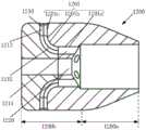
在本发明的一实施例中,如图3及图4所示,所述导向面1201包括沿近端向远端依次平滑连接的第一子导向面1201a、第二子导向面1201b、以及第三子导向面1201c。其中,所述第一子导向面1201a和所述第三子导向面1201c的轴线均为直线,两者之间所形成的夹角的角度为45°~135°。所述第二子导向面1201b的轴线为弧线,从而在平行于所述固定头1200的轴向的截面上,所述第二子导向面1201的轮廓线的至少一部分为曲线。如此,当所述丝线20的远端穿过所述穿线通道1210时,在所述导向面1201的支撑下,所述丝线20在所述穿线通道1210的出口处(即所述第三子导向面1201c远离所述第二子导向面1201b的端部处)的延伸方向相对于所述丝线20在所述穿线通道1210的入口处的延伸方向来说,其偏转的角度至少可以在45°~135°范围内选择。In one embodiment of the present invention, as shown in FIG. 3 and FIG. 4 , the
可选地,所述固定头1200上还形成有一安装通孔1220,所述固定头1200通过所述安装通孔1220安装于所述内管体1100上。所述穿线通道1210包括穿线孔(图中未标注),所述穿线孔包括第一孔段1211,所述第一孔段1211的轴线与所述安装通孔1220的轴线相平行,并且,所述第一孔段1211的部分孔壁可构成所述第一子导向面1201a,于本实施例中,所述第一孔段1211的远离所述安装通孔1220的一侧的孔壁构成所述第一子导向面1201a。Optionally, an installation through
进一步地,所述穿线孔还可以包括第二孔段1212和第三孔段1213。其中,所述第二孔段1212的近端与所述第一孔段1212的远端连接,且所述第二孔段1212的部分孔壁构成所述第二子导向面1201b。所述第三孔段1213的近端与所述第二孔段1212的远端连接,且所述第三孔段1213的部分孔壁构成所述第三子导向面1201c。Further, the threading hole may also include a
进一步地,所述导向面1201的表面粗糙度Ra应当尽可能地小,以在释放或回收所述医用植入物2的过程中,进一步减小所述丝线20与所述导向面1201之间产生的摩擦力。优选地,所述导向面1201的表面粗糙度Ra可以小于或等于0.2。在一些实现方式中,可以通过材料的选择来减小所述导向面1201的表面粗糙度Ra,例如利用聚四氟乙烯、陶瓷、玻璃等较为光滑的材料来制造所述固定头1200,或者,所述固定头120包括基材和润滑涂层,所述基材上形成供所述丝线20穿过的通道,并在所述通道的部分表面上设置所述润滑涂层以形成所述导向面1201。在另一些实现方式中,所述固定头1200可以为金属结构件,并通过对所述穿线通道1210的表面进行打磨、抛光等处理以降低所述导向面1201的表面粗糙度Ra,在此,所述固定头1200的材料包括但不限于碳氮化钛、氮化钛、不锈钢、镍钛中的任意一种。Further, the surface roughness Ra of the
可选地,所述穿线通道1210的数量根据实际需要设置,其可以为一个,也可以为两个、三个、或者更多个。如图2至图4所示,当所述穿线通道1210的数量为两个以上时,优选两个以上的所述穿线通道1210环绕所述安装通孔1220间隔布置,以减小所述固定头1200的径向尺寸,进而减小所述输送系统1的径向尺寸。可选地,多个所述穿线通道1210的出口位于同一圆周上,或者至少部分所述穿线通道1210的出口位于不同的圆周上。Optionally, the number of the
此外,本实施例中,如图2至图4所示,所述固定头1200具有流线型的外形,其包括轴向连接的近端节段1200a和远端节段1200b,所述近端节段1200a的横截面的面积沿近端向远端的方向逐渐增大。这样做的好处在于可以改善所述输送系统1的弯曲性能,有利于所述输送系统1穿过迂曲血管,同时与血管的干涉少,减少对血管的损伤。In addition, in this embodiment, as shown in FIGS. 2 to 4 , the fixing
另外,本实施例中,所述固定头1200可以为一体式构件,也可以是拼装式构件,只要所述固定头1200上能够形成所述穿线通道1210及所述安装通孔1220即可。In addition, in this embodiment, the fixing
请再参考图7,在本发明的另一实施例中,所述固定头1200至少包括固定头本体1230和转动件1240。所述固定头本体1230的中心位置形成有一第一插入孔,以作为所述安装通孔1220的至少一部分。所述固定头本体1230上还形成有沿在轴向上贯穿所述固定头本体1230的穿线槽1231,可选地,所述穿线槽1231沿所述固定头本体1230的径向延伸,并在所述固定头本体1230的边缘处开口,所述穿线槽1231为U型槽或扇形槽。所述转动件1240可转动地连接于所述穿线槽1231的槽壁上,并与所述穿线槽1231的至少部分槽壁围合形成所述穿线通道1210。所述转动件1240具有圆周面,所述圆周面的部分区域构成所述导向面1201。通常,所述圆周面背离所述开口的一侧的至少部分区域构成所述导向面1201,也即所述圆周面的朝向所述安装通孔1220的一侧的至少部分区域构成所述导向面1201。当所述丝线20的远端穿过所述穿线通道1210,并抵靠在所述转动件1240上时,所述丝线20的远端的延伸方向能够发生偏转(如图10所示)。也就是说,本实施例中利用所述转动件1240的部分表面作为所述丝线20的进行方向偏转时的支撑,使得所述丝线20与所述固定头1200之间的摩擦力为滚动摩擦,达到减少控制力损失的目的。Please refer to FIG. 7 again, in another embodiment of the present invention, the fixing
在一些实现方式中,所述固定头本体1230可具有较小的轴向尺寸,在此,如图8及图9所示,所述固定头1200还可以包括一底座1250,所述底座1250与所述固定座本体1230的近端端面连接,所述底座1250上还设有与所述第一插入孔对应的第二插入孔,所述第二插入孔与所述第一插入孔共同构成所述安装通孔1220。以及,所述底座1250上还可以设有与所述穿线通道相连通的导入通道1251,所述丝线20的远端穿过所述导入通道1251,再穿过所述穿线通道1210。所述导入通道1251可以设置于所述底座1250的对应于所述穿线通道1201的位置,其可以是孔(如图8及图9所示),例如圆形孔、方形孔等。需要说明的是,本发明实施例对所述导入通道的设置位置并没有特别限制,只要其能允许所述丝线20的远端穿过并进入所述穿线通道1210即可。此外,还优选所述底座1250的横截面积沿近端向远端的方向逐渐增大,以改善所述输送系统1的弯曲性能。可以理解,所述底座1250和所述固定头本体1230可以一体成型,也可以分体成型后再连接于一体。替代性地,所述固定头本体1230可具有较大的轴向尺寸,这种情况下,优选所述固定头本体1230的横截面沿近端向远端的方向逐渐增大。进一步地,本实施例中,所述转动件1240可以是一旋转轴,所述旋转轴通过轴承安装于所述穿线槽1231的槽壁上。或者,所述穿线槽1231的相对两个槽壁上形成有安装轴(图中未示出),所述转动件1240为一定滑轮,所述定滑轮可转动地安装于所述安装轴上。以及,所述转动件1240优选为金属结构件,其材料包括但不限于碳氮化钛、氮化钛、不锈钢、镍钛中的任意一种。优选地,所述转动件1240的圆周面上设有定位槽1241,所述定位槽1241沿所述转动件1240的周向延伸一圈,所述定位槽1241的部分槽壁(即所述定位槽1241的朝向安装通孔的部分)构成所述导向面1201。所述丝线20在穿过所述穿线通道1210时被限制在所述定位槽1241中,避免所述丝线20因在所述转动件1240的轴向上具有较大的移动范围而对所述医用植入物2的释放或回收产生不利影响。进一步优选地,在所述转动件1240的纵截面上,所述定位槽1241的形状为弧形。本发明实施例所提供的输送系统1,通过对所述固定头1200的结构进行优化,以降低所述丝线20在穿过所述固定头1200上的所述穿线通道1210时的摩擦力,达到减小在释放或回收所述医用植入物2时的控制力损失的问题,进而达到改善所述医用植入物2的稳定释放或回收、减小医用植入物2在释放或回收时对人体组织的损伤的效果。不仅如此,所述输送系统1在释放或回收所述医用植入物2时,还能够很好地克服所述医用植入物2的轴向移位的问题,提高所述医用植入物2的定位准确性。In some implementations, the fixing
进一步地,本发明实施例还提供了一种固定头,所述固定头为前述的固定头1200。Further, the embodiment of the present invention also provides a fixing head, and the fixing head is the
再进一步地,本发明实施例还提供了一种用于输送系统的内管机构,所述内管机构为前述的内管机构1000。Still further, the embodiment of the present invention also provides an inner tube mechanism for a delivery system, the inner tube mechanism is the aforementioned
更进一步地,本发明实施例还提供了一种用于输送系统的导管组件,所述导管组件为前述的导管组件100。Furthermore, an embodiment of the present invention also provides a catheter assembly for a delivery system, the catheter assembly being the
以及,本发明实施例还提供了一种医用装置,所述医用装置包括前述的输送系统1及所述医用植入物2。And, the embodiment of the present invention also provides a medical device, which includes the aforementioned delivery system 1 and the
本发明实施例对所述输送器所包括的固定头1200的数量和设置位置没有特别限制,只要所述丝线20的远端能够在所述导向面1201的作用下转向,并与所述医用植入物2连接即可。例如,所述固定头1200为一个(如图11、图12、图14及图15所示)、两个(如图13所示)、以及更多个(图中未示出),所述固定头1200可以设置在所述医用植入物2的近端侧和/或远端侧(如图11、图12及图13所示),所述固定头也可以设在所述医用植入物2的内侧(如图14及图15所示)。The embodiment of the present invention has no special limitation on the number and location of the fixed
在一个优选的实施例中,如图11、图12及图13所示,所述输送器包括至少一个所述固定头1200,且在所述输送系统的1的轴向上,任一个所述固定头1200与所述医用植入物2之间的距离大于或等于零(如图11及图13所示),且当所述医用植入物2处于压握状态时,所述固定头1200的所述导向面1201使所述丝线20的延伸方向偏转预定角度。具体来说,当所述固定头1200设置在所述医用植入物2的近端侧,且所述固定头1200的远端与所述医用植入物2的近端的距离大于或等于0,同时所述导向面1201使所述丝线20的延伸方向偏转90°~135°(即所述丝线20的位于所述固定头1200与所述医用植入物2之间的部分与所述输送器的轴线所形成的夹角α的角度为90°~135°)。和/或,所述固定头1200设置在所述医用植入物2的远端侧,且所述固定头1200的近端与所述医用植入物的远端的距离大于或等于0,同时所述导向面1201使所述丝线的延伸方向偏转45°~90°(即所述丝线20的位于所述固定头1200与所述医用植入物2之间的部分与所述输送器的轴线所形成的夹角α的角度为45°~90°)。这样设置的目的是,当所述医用植入物2被压缩时,所述医用植入物2与所述固定头1200之间在轴向上没有重合,两者不接触,可以改善整个医用装置的柔软度,从而所述医用装置能够更好地适应迂曲的血管。优选地,所述医用植入物2与所述内管体1100同轴布置。In a preferred embodiment, as shown in Figure 11, Figure 12 and Figure 13, the conveyor includes at least one
此外,本领域技术人员可以理解,当所述医用植入物2被释放并径向扩张时,所述丝线20的位于所述固定头1200与所述医用植入物2之间的部分与所述内管体1100的轴线所形成的夹角α的角度会相应发生改变,举例来说,当所述固定头1200设置于所述医用植入物2的近端侧时,所述医用植入物2被释放后,所述夹角α的角度减小,当所述固定头1200设置在所述医用植入物2的远端侧时,所述医用植入物2被释放后,所述夹角α的角度增大。In addition, those skilled in the art can understand that when the
虽然本发明披露如上,但并不局限于此。本领域的技术人员可以对本发明进行各种改动和变型而不脱离本发明的精神和范围。这样,倘若本发明的这些修改和变型属于本发明权利要求及其等同技术的范围之内,则本发明也意图包含这些改动和变型在内。Although the present invention is disclosed above, it is not limited thereto. Those skilled in the art can make various changes and modifications to the present invention without departing from the spirit and scope of the present invention. Thus, if these modifications and variations of the present invention fall within the scope of the claims of the present invention and their equivalent technologies, the present invention also intends to include these modifications and variations.
Claims (17)
Translated fromChinesePriority Applications (2)
| Application Number | Priority Date | Filing Date | Title |
|---|---|---|---|
| CN202111302111.4ACN116059023A (en) | 2021-11-04 | 2021-11-04 | Fixed head, delivery system and its inner tube mechanism, catheter assembly, and medical device |
| PCT/CN2022/119267WO2023061148A1 (en) | 2021-10-12 | 2022-09-16 | Implant conveying device |
Applications Claiming Priority (1)
| Application Number | Priority Date | Filing Date | Title |
|---|---|---|---|
| CN202111302111.4ACN116059023A (en) | 2021-11-04 | 2021-11-04 | Fixed head, delivery system and its inner tube mechanism, catheter assembly, and medical device |
Publications (1)
| Publication Number | Publication Date |
|---|---|
| CN116059023Atrue CN116059023A (en) | 2023-05-05 |
Family
ID=86180860
Family Applications (1)
| Application Number | Title | Priority Date | Filing Date |
|---|---|---|---|
| CN202111302111.4APendingCN116059023A (en) | 2021-10-12 | 2021-11-04 | Fixed head, delivery system and its inner tube mechanism, catheter assembly, and medical device |
Country Status (1)
| Country | Link |
|---|---|
| CN (1) | CN116059023A (en) |
Citations (7)
| Publication number | Priority date | Publication date | Assignee | Title |
|---|---|---|---|---|
| CN204874946U (en)* | 2015-07-09 | 2015-12-16 | 杭州永兴化纤有限公司 | Prevent seal wire pipe of broken string |
| CN105188612A (en)* | 2013-05-20 | 2015-12-23 | 爱德华兹生命科学公司 | Prosthetic Heart Valve Delivery Device |
| CN110198686A (en)* | 2016-11-18 | 2019-09-03 | 科菲瓣膜技术有限公司 | Cardiac valve delivery device and system |
| CN211658432U (en)* | 2020-01-21 | 2020-10-13 | 杭州市第三人民医院 | Ureter support hook is pulled out ware and is drawn line and prevent disconnected structure |
| CN212799178U (en)* | 2020-07-21 | 2021-03-26 | 广东台菱电梯有限公司 | Elevator rope head assembly capable of reducing friction of steel wire rope |
| CN113274177A (en)* | 2021-06-04 | 2021-08-20 | 成都百瑞恒通医疗科技有限公司 | Artery stent conveying system |
| CN216168132U (en)* | 2021-11-04 | 2022-04-05 | 上海微创心通医疗科技有限公司 | Fixing head, conveying system, inner tube mechanism of conveying system, catheter assembly and medical device |
- 2021
- 2021-11-04CNCN202111302111.4Apatent/CN116059023A/enactivePending
Patent Citations (7)
| Publication number | Priority date | Publication date | Assignee | Title |
|---|---|---|---|---|
| CN105188612A (en)* | 2013-05-20 | 2015-12-23 | 爱德华兹生命科学公司 | Prosthetic Heart Valve Delivery Device |
| CN204874946U (en)* | 2015-07-09 | 2015-12-16 | 杭州永兴化纤有限公司 | Prevent seal wire pipe of broken string |
| CN110198686A (en)* | 2016-11-18 | 2019-09-03 | 科菲瓣膜技术有限公司 | Cardiac valve delivery device and system |
| CN211658432U (en)* | 2020-01-21 | 2020-10-13 | 杭州市第三人民医院 | Ureter support hook is pulled out ware and is drawn line and prevent disconnected structure |
| CN212799178U (en)* | 2020-07-21 | 2021-03-26 | 广东台菱电梯有限公司 | Elevator rope head assembly capable of reducing friction of steel wire rope |
| CN113274177A (en)* | 2021-06-04 | 2021-08-20 | 成都百瑞恒通医疗科技有限公司 | Artery stent conveying system |
| CN216168132U (en)* | 2021-11-04 | 2022-04-05 | 上海微创心通医疗科技有限公司 | Fixing head, conveying system, inner tube mechanism of conveying system, catheter assembly and medical device |
Similar Documents
| Publication | Publication Date | Title |
|---|---|---|
| US10213300B2 (en) | Hypotube shaft with articulation mechanism | |
| US20120303005A1 (en) | Torque Shaft and Torque Drive | |
| US11623071B2 (en) | Guide wire activation mechanism and proximal actuation mechanism | |
| EP3378376B1 (en) | Endoscope system | |
| EP2865406A1 (en) | Guide wire | |
| CN216168132U (en) | Fixing head, conveying system, inner tube mechanism of conveying system, catheter assembly and medical device | |
| WO2022257700A1 (en) | Delivery device and medical apparatus | |
| CN112438824A (en) | Medical implant delivery device | |
| US12193641B2 (en) | Endoscope system | |
| US20170000311A1 (en) | Stent delivery system and endoscope system | |
| JP5313613B2 (en) | catheter | |
| JP2007529275A (en) | Second wire device and mounting procedure | |
| CN110811927A (en) | Implant loading device | |
| CN116059023A (en) | Fixed head, delivery system and its inner tube mechanism, catheter assembly, and medical device | |
| US9402756B2 (en) | Monorail | |
| CN100563601C (en) | Elastic transfer system | |
| US12156638B2 (en) | Medical device and treatment system | |
| CN113613603A (en) | stent delivery device | |
| JP6937042B2 (en) | Tube stent delivery system | |
| JP2017217251A (en) | Guide catheter | |
| CN116807700B (en) | Handle, conveying device and medical system | |
| US20240245539A1 (en) | Stent and stent delivery system | |
| JP2003320034A (en) | Device for inserting medical tool | |
| JP7664113B2 (en) | Supported Devices | |
| CN223054895U (en) | Delivery guidewire and stent delivery system |
Legal Events
| Date | Code | Title | Description |
|---|---|---|---|
| PB01 | Publication | ||
| PB01 | Publication | ||
| SE01 | Entry into force of request for substantive examination | ||
| SE01 | Entry into force of request for substantive examination |