CN116056668A - Rigid braid member for prosthetic valve delivery device - Google Patents
Rigid braid member for prosthetic valve delivery deviceDownload PDFInfo
- Publication number
- CN116056668A CN116056668ACN202180056251.XACN202180056251ACN116056668ACN 116056668 ACN116056668 ACN 116056668ACN 202180056251 ACN202180056251 ACN 202180056251ACN 116056668 ACN116056668 ACN 116056668A
- Authority
- CN
- China
- Prior art keywords
- yarns
- braid
- braided member
- yarn
- knitted component
- Prior art date
- Legal status (The legal status is an assumption and is not a legal conclusion. Google has not performed a legal analysis and makes no representation as to the accuracy of the status listed.)
- Pending
Links
Images


Classifications
- A—HUMAN NECESSITIES
- A61—MEDICAL OR VETERINARY SCIENCE; HYGIENE
- A61F—FILTERS IMPLANTABLE INTO BLOOD VESSELS; PROSTHESES; DEVICES PROVIDING PATENCY TO, OR PREVENTING COLLAPSING OF, TUBULAR STRUCTURES OF THE BODY, e.g. STENTS; ORTHOPAEDIC, NURSING OR CONTRACEPTIVE DEVICES; FOMENTATION; TREATMENT OR PROTECTION OF EYES OR EARS; BANDAGES, DRESSINGS OR ABSORBENT PADS; FIRST-AID KITS
- A61F2/00—Filters implantable into blood vessels; Prostheses, i.e. artificial substitutes or replacements for parts of the body; Appliances for connecting them with the body; Devices providing patency to, or preventing collapsing of, tubular structures of the body, e.g. stents
- A61F2/95—Instruments specially adapted for placement or removal of stents or stent-grafts
- A61F2/9517—Instruments specially adapted for placement or removal of stents or stent-grafts handle assemblies therefor
- A—HUMAN NECESSITIES
- A61—MEDICAL OR VETERINARY SCIENCE; HYGIENE
- A61F—FILTERS IMPLANTABLE INTO BLOOD VESSELS; PROSTHESES; DEVICES PROVIDING PATENCY TO, OR PREVENTING COLLAPSING OF, TUBULAR STRUCTURES OF THE BODY, e.g. STENTS; ORTHOPAEDIC, NURSING OR CONTRACEPTIVE DEVICES; FOMENTATION; TREATMENT OR PROTECTION OF EYES OR EARS; BANDAGES, DRESSINGS OR ABSORBENT PADS; FIRST-AID KITS
- A61F2/00—Filters implantable into blood vessels; Prostheses, i.e. artificial substitutes or replacements for parts of the body; Appliances for connecting them with the body; Devices providing patency to, or preventing collapsing of, tubular structures of the body, e.g. stents
- A61F2/02—Prostheses implantable into the body
- A61F2/24—Heart valves ; Vascular valves, e.g. venous valves; Heart implants, e.g. passive devices for improving the function of the native valve or the heart muscle; Transmyocardial revascularisation [TMR] devices; Valves implantable in the body
- A61F2/2442—Annuloplasty rings or inserts for correcting the valve shape; Implants for improving the function of a native heart valve
- A61F2/2466—Delivery devices therefor
- A—HUMAN NECESSITIES
- A61—MEDICAL OR VETERINARY SCIENCE; HYGIENE
- A61F—FILTERS IMPLANTABLE INTO BLOOD VESSELS; PROSTHESES; DEVICES PROVIDING PATENCY TO, OR PREVENTING COLLAPSING OF, TUBULAR STRUCTURES OF THE BODY, e.g. STENTS; ORTHOPAEDIC, NURSING OR CONTRACEPTIVE DEVICES; FOMENTATION; TREATMENT OR PROTECTION OF EYES OR EARS; BANDAGES, DRESSINGS OR ABSORBENT PADS; FIRST-AID KITS
- A61F2/00—Filters implantable into blood vessels; Prostheses, i.e. artificial substitutes or replacements for parts of the body; Appliances for connecting them with the body; Devices providing patency to, or preventing collapsing of, tubular structures of the body, e.g. stents
- A61F2/02—Prostheses implantable into the body
- A61F2/24—Heart valves ; Vascular valves, e.g. venous valves; Heart implants, e.g. passive devices for improving the function of the native valve or the heart muscle; Transmyocardial revascularisation [TMR] devices; Valves implantable in the body
- A61F2/2427—Devices for manipulating or deploying heart valves during implantation
- A61F2/2439—Expansion controlled by filaments
- D—TEXTILES; PAPER
- D04—BRAIDING; LACE-MAKING; KNITTING; TRIMMINGS; NON-WOVEN FABRICS
- D04C—BRAIDING OR MANUFACTURE OF LACE, INCLUDING BOBBIN-NET OR CARBONISED LACE; BRAIDING MACHINES; BRAID; LACE
- D04C3/00—Braiding or lacing machines
- D04C3/02—Braiding or lacing machines with spool carriers guided by track plates or by bobbin heads exclusively
- D04C3/06—Braiding or lacing machines with spool carriers guided by track plates or by bobbin heads exclusively with spool carriers moving always in the same direction in endless paths
- D—TEXTILES; PAPER
- D04—BRAIDING; LACE-MAKING; KNITTING; TRIMMINGS; NON-WOVEN FABRICS
- D04C—BRAIDING OR MANUFACTURE OF LACE, INCLUDING BOBBIN-NET OR CARBONISED LACE; BRAIDING MACHINES; BRAID; LACE
- D04C3/00—Braiding or lacing machines
- D04C3/02—Braiding or lacing machines with spool carriers guided by track plates or by bobbin heads exclusively
- D04C3/08—Braiding or lacing machines with spool carriers guided by track plates or by bobbin heads exclusively with means for superimposing threads or braids
- A—HUMAN NECESSITIES
- A61—MEDICAL OR VETERINARY SCIENCE; HYGIENE
- A61F—FILTERS IMPLANTABLE INTO BLOOD VESSELS; PROSTHESES; DEVICES PROVIDING PATENCY TO, OR PREVENTING COLLAPSING OF, TUBULAR STRUCTURES OF THE BODY, e.g. STENTS; ORTHOPAEDIC, NURSING OR CONTRACEPTIVE DEVICES; FOMENTATION; TREATMENT OR PROTECTION OF EYES OR EARS; BANDAGES, DRESSINGS OR ABSORBENT PADS; FIRST-AID KITS
- A61F2/00—Filters implantable into blood vessels; Prostheses, i.e. artificial substitutes or replacements for parts of the body; Appliances for connecting them with the body; Devices providing patency to, or preventing collapsing of, tubular structures of the body, e.g. stents
- A61F2/95—Instruments specially adapted for placement or removal of stents or stent-grafts
- A61F2002/9505—Instruments specially adapted for placement or removal of stents or stent-grafts having retaining means other than an outer sleeve, e.g. male-female connector between stent and instrument
- A61F2002/9511—Instruments specially adapted for placement or removal of stents or stent-grafts having retaining means other than an outer sleeve, e.g. male-female connector between stent and instrument the retaining means being filaments or wires
- A—HUMAN NECESSITIES
- A61—MEDICAL OR VETERINARY SCIENCE; HYGIENE
- A61F—FILTERS IMPLANTABLE INTO BLOOD VESSELS; PROSTHESES; DEVICES PROVIDING PATENCY TO, OR PREVENTING COLLAPSING OF, TUBULAR STRUCTURES OF THE BODY, e.g. STENTS; ORTHOPAEDIC, NURSING OR CONTRACEPTIVE DEVICES; FOMENTATION; TREATMENT OR PROTECTION OF EYES OR EARS; BANDAGES, DRESSINGS OR ABSORBENT PADS; FIRST-AID KITS
- A61F2250/00—Special features of prostheses classified in groups A61F2/00 - A61F2/26 or A61F2/82 or A61F9/00 or A61F11/00 or subgroups thereof
- A61F2250/0014—Special features of prostheses classified in groups A61F2/00 - A61F2/26 or A61F2/82 or A61F9/00 or A61F11/00 or subgroups thereof having different values of a given property or geometrical feature, e.g. mechanical property or material property, at different locations within the same prosthesis
- A61F2250/0015—Special features of prostheses classified in groups A61F2/00 - A61F2/26 or A61F2/82 or A61F9/00 or A61F11/00 or subgroups thereof having different values of a given property or geometrical feature, e.g. mechanical property or material property, at different locations within the same prosthesis differing in density or specific weight
- A61F2250/0017—Special features of prostheses classified in groups A61F2/00 - A61F2/26 or A61F2/82 or A61F9/00 or A61F11/00 or subgroups thereof having different values of a given property or geometrical feature, e.g. mechanical property or material property, at different locations within the same prosthesis differing in density or specific weight differing in yarn density
- D—TEXTILES; PAPER
- D10—INDEXING SCHEME ASSOCIATED WITH SUBLASSES OF SECTION D, RELATING TO TEXTILES
- D10B—INDEXING SCHEME ASSOCIATED WITH SUBLASSES OF SECTION D, RELATING TO TEXTILES
- D10B2509/00—Medical; Hygiene
- D10B2509/06—Vascular grafts; stents
Landscapes
- Health & Medical Sciences (AREA)
- Cardiology (AREA)
- Engineering & Computer Science (AREA)
- Biomedical Technology (AREA)
- Transplantation (AREA)
- Oral & Maxillofacial Surgery (AREA)
- Heart & Thoracic Surgery (AREA)
- Vascular Medicine (AREA)
- Life Sciences & Earth Sciences (AREA)
- Animal Behavior & Ethology (AREA)
- General Health & Medical Sciences (AREA)
- Public Health (AREA)
- Veterinary Medicine (AREA)
- Textile Engineering (AREA)
- Prostheses (AREA)
Abstract
Description
Translated fromChinese相关申请的交叉引用Cross References to Related Applications
本申请要求于2020年6月11日提交的标题为“用于假体瓣膜递送设备的刚性编织物构件(STIFF BRAID MEMBER FOR PROSTHETIC VALVED ELIVERY APPARATUS)”的美国临时申请序列号63/037,779的权益,该申请通过引用并入本文。This application claims the benefit of U.S. Provisional Application Serial No. 63/037,779, entitled "STIFF BRAID MEMBER FOR PROSTHETIC VALVED ELIVERY APPARATUS," filed June 11, 2020, This application is incorporated herein by reference.
技术领域technical field
本公开涉及可植入的假体装置,如假体心脏瓣膜,并且涉及用于植入假体心脏瓣膜的递送设备和方法。The present disclosure relates to implantable prosthetic devices, such as prosthetic heart valves, and to delivery devices and methods for implanting prosthetic heart valves.
背景技术Background technique
人的心脏可能患有各种瓣膜病。这些瓣膜病可导致心脏严重功能障碍,并且最终需要修复天然瓣膜或用人造瓣膜更换天然瓣膜。有许多已知的修复装置(例如,支架)和人造瓣膜,以及许多已知的将这些装置和瓣膜植入人体的方法。经皮和微创外科方法用于各种程序中,以将假体医学装置递送到外科不易接近或期望在不需要外科的情况下接近的身体内部位置。在一个具体实例中,可以将假体心脏瓣膜以折绉状态安装在递送设备的远端,并且推进通过患者的脉管系统(例如,通过股动脉和主动脉),直到假体瓣膜到达心脏中的植入部位。然后将假体心脏瓣膜扩张到其功能尺寸,例如,通过给安装有假体心脏瓣膜的球囊膨胀、启动向假体心脏瓣膜施加扩张力的机械致动器,或通过从递送设备的鞘部署假体心脏瓣膜,从而假体心脏瓣膜可自行扩张至其功能尺寸。The human heart can suffer from various valvular diseases. These valvular diseases can lead to severe heart dysfunction and eventually require repair of the natural valve or replacement of the natural valve with an artificial valve. There are many known prosthetic devices (eg, stents) and artificial valves, as well as many known methods of implanting these devices and valves in the human body. Percutaneous and minimally invasive surgical approaches are used in a variety of procedures to deliver prosthetic medical devices to internal body locations that are not surgically accessible or where access is desired without surgery. In one specific example, a prosthetic heart valve can be mounted in a creped state at the distal end of the delivery device and advanced through the patient's vasculature (e.g., through the femoral artery and aorta) until the prosthetic valve reaches the heart the implantation site. The prosthetic heart valve is then expanded to its functional size, for example, by inflating a balloon to which the prosthetic heart valve is mounted, actuating a mechanical actuator that applies an expansion force to the prosthetic heart valve, or by deployment from a sheath of a delivery device A prosthetic heart valve whereby the prosthetic heart valve expands on its own to its functional size.
考虑到典型递送设备中包含相对较多数量的小部件,装配工组装递送设备可能是困难的和/或耗时的。因此,需要改进的递送设备、组装递送设备的方法和植入假体心脏瓣膜的方法。Assembly of delivery devices may be difficult and/or time consuming for assemblers given the relatively large number of small parts contained in typical delivery devices. Accordingly, there is a need for improved delivery devices, methods of assembling delivery devices, and methods of implanting prosthetic heart valves.
发明内容Contents of the invention
本文描述的是假体心脏瓣膜、递送设备的实施方式和用于植入假体心脏瓣膜的方法。Described herein are prosthetic heart valves, embodiments of delivery devices, and methods for implanting a prosthetic heart valve.
在代表性实施方式中,编织构件可以包括第一组纱线,该第一组纱线沿第一方向延伸;第二组纱线,该第二组纱线沿第二方向延伸并且与第一组纱线缠结;和一组轴向纱线,该一组轴向纱线沿编织构件的纵向轴线延伸并且设置在第一组纱线和第二组纱线之间。编织构件包括管状编织物。In representative embodiments, a knitted member may include a first set of yarns extending in a first direction; a second set of yarns extending in a second direction and aligned with the first set of yarns. a set of entangled yarns; and a set of axial yarns extending along the longitudinal axis of the knitted member and disposed between the first set of yarns and the second set of yarns. The braided member includes a tubular braid.
在另一代表性实施方式中,编织构件可以包括:第一组纱线,该第一组纱线沿第一方向延伸;第二组纱线,该第二组纱线沿第二方向延伸并且与第一组纱线缠结;和一组轴向纱线。该轴向纱线可沿编织构件的纵向轴线延伸并且可设置在第一组纱线和第二组纱线之间。编织构件可具有在10PPI和400PPI之间的编织物密度。In another representative embodiment, a knitted member may include: a first set of yarns extending in a first direction; a second set of yarns extending in a second direction and entangled with the first set of yarns; and a set of axial yarns. The axial yarns can extend along the longitudinal axis of the knit member and can be disposed between the first set of yarns and the second set of yarns. The braided member may have a braid density between 10 PPI and 400 PPI.
在另一代表性实施方式中,编织构件可包括外层和内芯构件。外层可以包括第一组纱线,该第一组纱线沿第一方向延伸;第二组纱线,该第二组纱线沿第二方向延伸并且与第一组纱线缠结;和一组轴向纱线,该组轴向纱线沿编织构件的纵向轴线延伸并且设置在第一组纱线和第二组纱线之间。In another representative embodiment, a braided member may include an outer layer and an inner core member. The outer layer may include a first set of yarns extending in a first direction; a second set of yarns extending in a second direction and entangled with the first set of yarns; and A set of axial yarns extends along the longitudinal axis of the knitted member and is disposed between the first set of yarns and the second set of yarns.
在代表性实施方式中,力平衡组合件可包括两个或更多个致动构件,每个致动构件包括盖(cap)构件、至少一个滑轮构件和至少一个编织构件。该至少一个编织构件具有耦接到第一盖构件的第一端部、耦接到第二盖构件的第二端部和围绕该至少一个滑轮构件设置的主体部分。编织构件包括第一组纱线,该第一组纱线沿第一方向延伸;第二组纱线,该第二组纱线沿第二方向延伸并且与第一组纱线缠结;和一组轴向纱线,该轴向纱线沿编织构件的纵向轴线延伸并且设置在第一组纱线和第二组纱线之间。力平衡组合件可以被配置为在两个或更多个致动构件之间平均分配力,并且编织构件可以具有在10和400PPI之间的编织物密度。In representative embodiments, a force balancing assembly can include two or more actuation members, each actuation member including a cap member, at least one pulley member, and at least one braid member. The at least one braid member has a first end coupled to the first cover member, a second end coupled to the second cover member, and a body portion disposed about the at least one pulley member. The knit member includes a first set of yarns extending in a first direction; a second set of yarns extending in a second direction and entangled with the first set of yarns; and a A set of axial yarns extends along the longitudinal axis of the knit member and is disposed between the first set of yarns and the second set of yarns. The force balancing assembly can be configured to distribute force equally between the two or more actuation members, and the braid members can have a braid density between 10 and 400 PPI.
通过以下参照附图进行的详细描述,本发明的前述和其它目的、特征和优点将变得更加明显。The foregoing and other objects, features and advantages of the present invention will become more apparent from the following detailed description made with reference to the accompanying drawings.
附图说明Description of drawings
图1是用于假体心脏瓣膜的递送设备的示例性实施方式的侧正视图。Figure 1 is a side elevation view of an exemplary embodiment of a delivery device for a prosthetic heart valve.
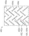
图2是编织物的示例性实施方式的一部分的侧正视图。Figure 2 is a side elevation view of a portion of an exemplary embodiment of a braid.
图3是图2所示编织物的一部分的简化图,其中编织物呈扁平构型。Fig. 3 is a simplified view of a portion of the braid shown in Fig. 2, wherein the braid is in a flat configuration.
图4A-图7B示例了编织物图案和编织物缠结技术的各种实例。4A-7B illustrate various examples of braid patterns and braid entanglement techniques.
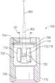
图8是包括图2的编织物的递送设备的一部分的局部横截面侧视图。8 is a partial cross-sectional side view of a portion of a delivery device including the braid of FIG. 2 .
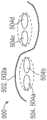
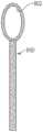
图9是包括环形部的编织物的示例性实施方式的侧正视图。9 is a side elevation view of an exemplary embodiment of a braid including loops.
图10是包括图9的编织物的递送设备的一部分的局部横截面侧视图。10 is a partial cross-sectional side view of a portion of a delivery device including the braid of FIG. 9 .
图11是根据一个实施方式的分叉编织物的侧视图。Figure 11 is a side view of a bifurcated braid according to one embodiment.
图12是根据一个实施方式的包括芯构件的编织物的横截面视图。Figure 12 is a cross-sectional view of a braid including a core member according to one embodiment.
图13是递送设备的另一个示例性实施方式的一部分的侧视图。Figure 13 is a side view of a portion of another exemplary embodiment of a delivery device.
具体实施方式Detailed ways
一般注意事项General Notes
出于本描述的目的,本文描述了本公开的实施方式的某些方面、优点和新颖特征。不应将所公开的方法、装置和系统解释为以任何方式进行限制。相反,本公开针对各种公开的实施方式的所有新颖的和非显而易见的特征和方面,其为单独地以及为彼此各种组合和子组合。方法、设备和系统不限于任何具体方面或特征或其组合,所公开的实施方式也不要求存在任何一个或多个具体优点或待解决问题。For purposes of this description, certain aspects, advantages and novel features of embodiments of the disclosure are described herein. The disclosed methods, devices and systems should not be construed as limiting in any way. Rather, the present disclosure is directed to all novel and non-obvious features and aspects of the various disclosed embodiments, individually and in various combinations and subcombinations with each other. The methods, apparatus and systems are not limited to any specific aspect or feature or combination thereof, nor do the disclosed embodiments require the existence of any one or more specific advantages or problems to be solved.
尽管公开的实施方式中的一些的操作以具体的、连续的顺序描述,以便于呈现,但是应当理解,这种描述方式包括涵盖排列,除非下文阐述的具体语言要求具体的顺序。例如,顺序描述的操作在一些情况下可以重新排列或同时执行。此外,为了简单起见,附图可能没有示其中公开的方法可以与其它方法结合使用的各种方式。此外,描述有时使用诸如“提供”或“实现”的术语来描述所公开的方法。这些术语是对所执行的实际操作的高级抽象。对应于这些术语的实际操作可以根据具体实施方案而变化,并且是本领域普通技术人员容易辨别的。Although operations of some of the disclosed embodiments are described in a specific, sequential order for ease of presentation, it should be understood that such description includes contemplative permutations unless specific language set forth below requires a specific order. For example, operations described sequentially may in some cases be rearranged or performed concurrently. Furthermore, for the sake of simplicity, the figures may not show the various ways in which the methods disclosed therein may be used in combination with other methods. Furthermore, the description sometimes uses terms such as "provide" or "implement" to describe the disclosed methods. These terms are a high-level abstraction of the actual operation being performed. The actual operations that correspond to these terms may vary depending on the particular implementation, and are readily discernible to those of ordinary skill in the art.
本文描述的所有特征彼此独立,并且除了结构上不可能的情况外,可以与本文描述的任何其它特征结合使用。All features described herein are independent of each other and, except where structurally impossible, can be used in combination with any other feature described herein.
如在本申请和权利要求中使用的,单数形式“一(a)”、“一个(an)”和“该/所述(the)”包括复数形式,除非上下文另有明确规定。此外,术语“包括”意指“包含”。此外,术语“耦接”和“相关联”通常意指电气、电磁和/或物理(例如,机械或化学)耦接或连接,并且不排除在没有具体相反语言的耦接或相关联项目之间存在中间元素。As used in this application and the claims, the singular forms "a", "an" and "the" include plural referents unless the context clearly dictates otherwise. Furthermore, the term "comprising" means "comprising". Furthermore, the terms "coupled" and "associated" generally mean electrical, electromagnetic, and/or physical (e.g., mechanical or chemical) coupling or connection, and do not exclude coupled or associated items without specific language to the contrary. There are intermediate elements.
在本申请的上下文中,术语“下面的”和“上面的”分别与术语“流入”和“流出”可互换使用。因此,例如,瓣膜的下端为其流入端并且瓣膜的上端为其流出端。In the context of this application, the terms "below" and "above" are used interchangeably with the terms "inflow" and "outflow", respectively. Thus, for example, the lower end of the valve is its inflow end and the upper end of the valve is its outflow end.
如本文所用,术语“近侧的”是指装置的位置、方向或部分更靠近使用者并且进一步远离植入部位。如本文所用,术语“远侧的”指的是装置的位置、方向或部分,其进一步远离使用者且更接近植入部位。因此,例如装置的近侧运动是装置朝向使用者的运动,而装置的侧运动是装置远离使用者的运动。除非另有明确定义,否则术语“纵向的”和“轴向的”是指在近侧和远侧方向上延伸的轴线。As used herein, the term "proximal" refers to a location, orientation or portion of a device that is closer to the user and further away from the implantation site. As used herein, the term "distal" refers to a location, orientation, or portion of a device that is further away from the user and closer to the implantation site. Thus, for example, proximal movement of the device is movement of the device towards the user, whereas lateral movement of the device is movement of the device away from the user. Unless expressly defined otherwise, the terms "longitudinal" and "axial" refer to an axis extending in the proximal and distal directions.
公开技术的实例Examples of Disclosed Technologies
本文描述的是假体心脏瓣膜、递送设备和用于植入假体心脏瓣膜的方法。例如,所公开的递送设备和方法可用于植入可机械扩张的假体心脏瓣膜,如2020年9月30日提交的美国专利号10,603,165和美国临时申请号63/085,947中描述的瓣膜,其中每篇都通过引用并入本文。例如,一些机械瓣膜可以包括支柱之间的可枢转接合部,而其它机械瓣膜可以包括经由机械装置可扩展和/或可压缩的一体化网格框架。然而,应当理解,本文所述的递送设备还可与其它类型的经导管假体瓣膜包括球囊扩张假体心脏瓣膜一起使用,如美国专利号9,393,110和美国公开号U.S.2018/0028310和2019/0365530中公开的,其中每篇都通过引用并入本文,以及自扩张假体心脏瓣膜,如美国专利号10,098,734中公开的,其通过引用并入本文。Described herein are prosthetic heart valves, delivery devices, and methods for implanting a prosthetic heart valve. For example, the disclosed delivery devices and methods can be used to implant mechanically expandable prosthetic heart valves, such as those described in U.S. Patent No. 10,603,165 and U.S. Provisional Application No. 63/085,947, filed September 30, 2020, wherein each All are incorporated herein by reference. For example, some mechanical valves may include pivotable junctions between struts, while other mechanical valves may include an integral lattice frame that is expandable and/or compressible via mechanical means. However, it should be understood that the delivery devices described herein may also be used with other types of transcatheter prosthetic valves, including balloon-expandable prosthetic heart valves, such as U.S. Patent No. 9,393,110 and U.S. Publication Nos. U.S. 2018/0028310 and 2019/0365530 , each of which is incorporated herein by reference, and a self-expanding prosthetic heart valve, as disclosed in US Pat. No. 10,098,734, which is incorporated herein by reference.
图1示例了适于递送假体心脏瓣膜102的示例性递送设备100。假体瓣膜102可以可释放地耦接到递送设备100。进一步,应当理解,递送设备100和本文描述的递送设备的其它实施方式可用于植入除假体瓣膜之外的假体装置,如支架或移植物。FIG. 1 illustrates an
示例的实施方式中的递送设备100一般包括手柄104、从手柄104向远侧延伸的第一细长轴106(其包括示例的实施方式中的外轴)、向远侧延伸穿过外轴106的至少一个致动器组合件108。该至少一个致动器组合件108可被配置为在被致动时径向扩张和/或径向皱缩假体瓣膜102。The
尽管示例的实施方式为了示例的目的显示了两个致动器组合件108,但是应该理解可以为假体瓣膜102上的每个致动器提供一个致动器108。例如,可以为具有三个致动器的假体瓣膜提供三个致动器组合件108。在其它实施方式中,可以存在更多或更少数量的致动器组合件。Although the illustrated embodiment shows two
在一些实施方式中,轴106的远侧端部116的尺寸可以设计成在假体瓣膜递送通过患者脉管系统期间,容纳处于其径向压缩递送状态的假体瓣膜102。以这种方式,远侧端部116在递送期间用作假体瓣膜的递送鞘或胶囊。In some embodiments, the
致动器组合件108可以可释放地耦接到假体瓣膜102。例如,在示例的实施方式中,每个致动器组合件108可以耦接到假体瓣膜102的相应致动器。每个致动器组合件108可以包括支撑管、内部致动器构件(其可以是例如挠性张紧构件)和锁定工具。当被致动时,致动器组合件可将推力和/或拉力传递到假体瓣膜的部分,以如前所述径向扩张和皱缩假体瓣膜。致动器组合件108可至少部分地径向设置在外轴106的一个或多个内腔内,并且轴向延伸穿过外轴106的一个或多个内腔。例如,致动器组合件108可以延伸穿过轴106的中心内腔或穿过轴106中形成的分开的相应内腔。
递送设备100的手柄104可以包括一个或多个控制机构(例如,旋钮或其它致动机构),用于控制递送设备100的不同部件,以便扩张和/或部署假体瓣膜102。例如,在示例的实施方式中,手柄104包括第一旋钮110、第二旋钮112和第三旋钮114。Handle 104 of
第一旋钮110可以是可旋转的旋钮,该旋钮被配置为在远侧和/或近侧方向上产生外轴106相对于假体瓣膜102的轴向移动,以便在假体瓣膜已经被推进到患者身体期望的植入位置处或邻近其的位置时从递送鞘116部署假体瓣膜。例如,第一旋钮110沿第一方向(例如,顺时针)的旋转可以相对于假体瓣膜102向近侧缩回鞘116,并且第一旋钮110沿第二方向(例如,逆时针)的旋转可以向远侧推进鞘116。在其它实施方式中,第一旋钮110可以通过轴向滑动或移动旋钮110如拉动和/或推动旋钮来致动。在其它实施方式中,第一旋钮110的致动(旋钮110的旋转或滑动移动)可产生致动器组合件108(以及因此假体瓣膜102)相对于递送鞘116的轴向移动,以将假体瓣膜从鞘116向远侧推动。The
第二旋钮112可以是被配置为产生假体瓣膜102的径向扩张和/或收缩的可旋转旋钮。例如,第二旋钮112的旋转可以使致动器构件和支撑管相对于彼此轴向移动。第二旋钮112沿第一方向(例如,顺时针)的旋转可使假体瓣膜102径向扩张,并且第二旋钮112沿第二方向(例如,逆时针)的旋转可使假体瓣膜102径向皱缩。在其它实施方式中,第二旋钮112可以通过轴向滑动或移动旋钮112如拉动和/或推动旋钮来致动。
第三旋钮114可以是可旋转的旋钮,其被配置为将假体心脏瓣膜102保持在其扩张构型。例如,第三旋钮114可以可操作地连接到每个致动器组合件108的锁定工具的近侧端部。第三旋钮114沿第一方向(例如,顺时针)的旋转可以旋转每个锁定工具,以抵抗假体瓣膜的框架的径向压缩。旋钮114沿相反方向(例如,逆时针)的旋转可以沿相反方向旋转每个锁定工具,以从相应的内部致动器构件移除锁定工具。在其它实施方式中,第三旋钮114可以通过轴向滑动或移动第三旋钮114如拉动和/或推动旋钮来致动。
尽管未示出,但手柄104可包括可操作地连接到每个内部致动器构件的近侧端部的第四可旋转旋钮。第四旋钮可被配置为在旋钮旋转时旋转每个内部致动器构件,以将每个致动器构件从假体瓣膜102的近侧端部旋松。锁定工具和致动器构件从假体瓣膜102上旋松后,它们可以与支撑管一起从患者中移除。Although not shown, handle 104 may include a fourth rotatable knob operatively connected to the proximal end of each inner actuator member. The fourth knob may be configured to rotate each inner actuator member to unscrew each actuator member from the proximal end of the
在一些实施方式中,递送设备(例如,递送设备100)可以包括一个或多个挠性构件或缝线,用于例如将递送设备的各种部件彼此耦接。例如,在一些实施方式中,递送设备100的手柄104内的部件可以使用挠性构件耦接在一起,并且在其它实施方式中,诸如内部致动器构件的部件可以包括挠性构件。根据部件的性质,改变挠性构件的刚度、抗张强度、直径、长度和/或伸长率以满足系统的需求可能是有利的。在具体应用中,挠性构件可能需要具有选定的刚度和选定的直径。例如,挠性构件可以具有高刚度和相对小的直径,同时具有能够承受至少120N的施加力的强度。在一些实施方式中,挠性构件可以承受上至300N的施加力。In some embodiments, a delivery device (eg, delivery device 100 ) can include one or more flexible members or sutures, for example, to couple various components of the delivery device to each other. For example, in some implementations, components within
为了提供必要的强度和刚度,在一些实施方式中,挠性构件或缝线可以被配置为包括多根纱线的编织物。纱线可包含高韧度和/或超高强度材料。纱线可以是例如复丝(例如,每根纱线包含多根丝)或单丝纱(例如,每根纱线包含单根丝)并且可以通过编织成多种图案中的任一种而缠结,如下面参考图2-图7B更详细地描述的。To provide the necessary strength and stiffness, in some embodiments, the flexible member or suture can be configured as a braid comprising multiple yarns. Yarns may comprise high tenacity and/or ultra high strength materials. The yarns can be, for example, multifilament (e.g., each yarn contains multiple filaments) or monofilament yarns (e.g., each yarn contains a single filament) and can be wound by weaving into any of a variety of patterns. knot, as described in more detail below with reference to Figures 2-7B.
图2-3示出了示例性编织物200,其被配置为包括一根或多根轴向延伸纱线的“平纹(plain)编织物”。如图4A-图4B所示,平纹编织物构型300(也称为‘单纱线一上一下编织物(one yarn one-over,one-under braid)’)包括第一组纱线302和第二组纱线304,第一组纱线302和第二组纱线304以其中第一纱线302a以重复图案在第二纱线304a上方然后在下一第二纱线304b下方穿过的图案缠结。2-3 illustrate an
在其它实施方式中,编织物可以具有各种编织构型中的任何一种。例如,图5A-图5B示例了具有第一组纱线402和第二组纱线404的“规则编织物”构型400(也称为‘单纱线双上双下(one yarn two-over,two-under)’图案),其中第一纱线402a以重复图案穿过两根第二纱线404a、404b下方然后在下一组两根第二纱线404c、404d上方。图6A-图6B示例了“菱形编织物”构型500(也称为‘双纱线双上双下(two yarn two-over,two-under)’图案),其具有第一组纱线502和第二组纱线504并且其中两根第一纱线502a、502b以重复图案穿过两根第二纱线504a、504b上方然后穿过下一组两根第二纱线504c、504d下方。图7A-图7B示例了具有第一组纱线602和第二组纱线604的“赫格利斯(Hercules)编织物”构型600(也称为‘三纱线三上三下(three yarn three-over,three-under)’图案),其中三根第一纱线602a、602b、602c以重复图案穿过第一组三根第二纱线604a、604b、604c上方并且穿过第二组三根第二纱线604d、604e、604f上方。In other embodiments, the braid can have any of a variety of braid configurations. For example, Figures 5A-5B illustrate a "regular braid" configuration 400 (also known as a 'one yarn two-over , two-under)' pattern), wherein the
再次参考图2-3,平纹编织物可以被配置为管状编织物200。类似地,图4A-7B的任何编织构型可以被配置为管状编织物。编织物可包括复丝纱线构造,其包括第一组纱线202和第二组纱线204。第一组纱线202和第二组纱线204可包括复丝纱线或单丝纱线。第一组纱线202可以沿第一方向(例如,顺时针)螺旋和缠结,并且第二组纱线204可以沿第二方向(例如,逆时针)螺旋和缠结。第一组纱线202和第二组纱线204可以在圆形路径中缠结以形成管状编织物。图3示例了包括轴向纱线210的管状编织物200的扁平视图。Referring again to FIGS. 2-3 , the plain weave may be configured as
编织物200的刚度可根据以下编织物参数确定:编织物密度、纱线类型、纱线尺寸(例如线密度)、编织物中的纱线端数、编织物图案和/或编织物结构的布置(例如,管状编织物)、轴向纱线、芯构件和/或其任何组合。可以改变编织物参数以提供具有选定特性的编织物。下面结合平纹编织物200描述各种编织物参数、尺寸和其它特性。然而,应当注意,可以使用编织物参数、尺寸和其它特性的以下公开内容,以形成具有图4A-7B的编织构型中的任何一个或任何其它已知的编织构型的编织构件。此外,在平纹编织物200在本文中显示或描述为递送设备的部件的情况下,作为递送设备的部件的编织构件可包括本文公开的任何编织物构型。The stiffness of the
如所提及的,编织物200可具有至少部分地决定编织物的刚度的选定编织物密度。编织物密度可以使用每英寸纬数(picks per inck,PPI)的测量来确定。纬纱(pick)206,如图2所示,是两个相邻纱线交叉点208之间的区域。编织物的PPI是沿编织物200的纵向轴线每英寸的纬纱数。更高的PPI导致更刚性编织物,而更低地PPI导致更柔软的编织物。在一些实施方式中,编织物200可具有约10PPI至约400PPI、约25PPI至约300PPI、约50PPI至约200PPI、约75PPI至约150PPI等的编织物密度。在一些具体实施方式中,发现选定的75PPI编织物密度导致编织物200具有期望的刚度。在具体实施方式中,在编织物200的端部不解开(unravelling)的情况下,编织物200的刚度必须足以使编织物穿过小孔。也就是说,编织物200的纱线202、204不变得彼此分离。As mentioned,
在一些实施方式中,期望形成具有小于0.055英寸的选定直径的编织物。例如,在一些实施方式中,编织物200的直径可以在约0.024英寸和约0.055英寸之间。选定以形成编织物200的纱线的数量可以根据纱线的尺寸和/或编织物的选定直径而变化。在一些实施方式中,管状编织物可包括4至72根纱线。纱线的线密度(例如,每单位长度纱线质量的量度)可以例如在10dtex至500dtex之间。使用具有更低线密度的纱线的编织物可包含更多数量的纱线,而使用具有较高线密度的纱线的编织物可包含更少数量的纱线。例如,编织物可包括第一组32根纱线和第二组32根纱线,每根纱线具有25dtex的线密度。In some embodiments, it is desirable to form a braid having a selected diameter of less than 0.055 inches. For example, in some embodiments, the diameter of
对于其中期望直径小(例如,小于0.055英寸)的编织物,选择具有更小线密度(如110dtex)的纱线,允许编织物具有相对高数量的纱线;以及选择具有更大线密度(如440dtex)的纱线,允许编织物具有相对更少数量的纱线。例如,在具体实施方式中,管状编织物可包括16根纱线,每根纱线具有110dtex的线密度。16根纱线可分成第一组8根纱线和第二组8根纱线,并且可被缠结以形成直径小于0.055英寸的编织物。在另一个具体实施方式中,管状编织物可包括8根纱线,每根纱线具有440dtex的线密度。这8根纱线可以分成第一组4根纱线和第二组4根纱线,并且可被缠结以形成直径小于0.055英寸的编织物。For braids where a small diameter is desired (e.g., less than 0.055 inches), selecting yarns with a smaller linear density (such as 110 dtex) allows the braid to have a relatively high number of yarns; and selecting yarns with a larger linear density (such as 440dtex), allowing braids to have a relatively smaller number of yarns. For example, in particular embodiments, the tubular braid may include 16 yarns, each yarn having a linear density of 110 dtex. The 16 yarns can be divided into a first group of 8 yarns and a second group of 8 yarns, and can be entangled to form a braid having a diameter of less than 0.055 inches. In another embodiment, the tubular braid may comprise 8 yarns, each yarn having a linear density of 440 dtex. The 8 yarns can be separated into a first set of 4 yarns and a second set of 4 yarns, and can be entangled to form a braid having a diameter of less than 0.055 inches.
根据编织物的强度要求,纱线可以由各种材料中的任何一种形成。在一些实施方式中,材料可以是具有大于20克/旦尼尔(gpd)的韧度的合成聚合物。在其它实施方式中,材料可以选自天然纤维(例如,羊毛、丝绸、安哥拉兔毛、棉、亚麻、大麻、黄麻等)和/或合成纤维(例如,聚丙烯、尼龙、聚酯、聚乙烯、芳族聚酰胺、聚芳酰胺、液晶聚合物等)。在其中编织物能够承受至少120N的施加力的一些具体应用中,纱线可以是超高分子量聚乙烯(UHMWPE)。在一些实施方式中,纱线可以是生物相容的纱线。在一些这样的实施方式中,生物相容性纱线可以形成被配置为植入患者体内的生物相容性编织构件。Depending on the strength requirements of the braid, the yarns can be formed from any of a variety of materials. In some embodiments, the material can be a synthetic polymer having a tenacity greater than 20 grams per denier (gpd). In other embodiments, the material may be selected from natural fibers (e.g., wool, silk, angora, cotton, linen, hemp, jute, etc.) and/or synthetic fibers (e.g., polypropylene, nylon, polyester, polyethylene , aramid, polyaramid, liquid crystal polymer, etc.). In some specific applications where the braid is capable of withstanding an applied force of at least 120N, the yarns may be ultra high molecular weight polyethylene (UHMWPE). In some embodiments, the yarn can be a biocompatible yarn. In some such embodiments, the biocompatible yarn can form a biocompatible braided member configured to be implanted in a patient.
在一些实施方式中,编织物200可以使用“maypole”技术形成。第一组纱线202和第二组纱线204中的每根纱线都可以耦接到相应的卷轴,并且卷轴可以在彼此上方或下方缠结。卷轴的一半(例如,耦接到第一组纱线202的那些)可以沿第一(例如,顺时针)方向移动,而卷轴的另一半(例如,耦接到第二组纱线204的那些)可以沿第二(例如,逆时针)方向移动。这样的构型可以产生具有相对光滑外表面的编织物200。光滑外表面有利地防止或减轻编织物200在使用时在部件(例如,递送设备的部件)上卡住和/或撕裂。In some embodiments,
在一些实施方式中,可以使用载体编织机来执行maypole技术。载体编织机可被配置为承载8至72根具有约10dtex至约500dtex之间的线密度的纱线。在一些具体的实施方式中,载体编织机可以承载具有约55dtex的线密度的16根(ends of)纱线(被配置为第一组8根纱线和第二组8根纱线)。在其它实施方式中,载体编织机可承载具有约25dtex的线密度的64根纱线(被配置为第一组32根纱线和第二组32根纱线)。In some embodiments, the maypole technique can be performed using a carrier weaving machine. The carrier knitting machine may be configured to carry 8 to 72 yarns having a linear density between about 10 dtex and about 500 dtex. In some specific embodiments, the carrier knitting machine can carry 16 ends of yarn (configured as a first set of 8 yarns and a second set of 8 yarns) having a linear density of about 55 dtex. In other embodiments, the carrier knitting machine can carry 64 yarns (configured as a first set of 32 yarns and a second set of 32 yarns) having a linear density of about 25 dtex.
在一些实施方式中,如图2-图3示例的实施方式,编织物200可包括一根或多根轴向延伸的纱线210(也称为“轴向纱线”)。轴向纱线210可被配置成为编织物200提供其它的刚度和/或强度。轴向纱线210可以是例如复丝纱线、单丝纱线和/或编织纱线。在一些实施方式中,轴向纱线210可以是具有约0.001英寸和约0.04英寸之间直径的单丝纱线。在其它实施方式中,轴向纱线210可以是复丝纱线,其中复丝纱线包括例如5根丝,每根丝具有0.001英寸的直径。In some embodiments, such as the embodiment illustrated in FIGS. 2-3 ,
轴向纱线210可由多种材料中的任何一种形成。在一些实施方式中,材料可以是具有大于20克/旦尼尔(gpd)的韧度的合成聚合物。在一些实施方式中,材料可包括天然纤维(例如,羊毛、丝绸、安哥拉兔毛、棉、亚麻、大麻、黄麻等)和/或合成纤维(例如,聚丙烯、尼龙、聚酯、聚乙烯、芳族聚酰胺、聚芳酰胺等)。在一些具体应用中,轴向纱线210可包含超高分子量聚乙烯(UHMWPE)。在一些其它具体实施方式中,轴向纱线可包含液晶聚合物(LCP)。在一些实施方式中,轴向纱线可以是生物相容性纱线。
如图2所示,轴向纱线210可基本上平行于编织物200的纵轴延伸。轴向纱线210可以在选定位置上与第一组纱线202和/或第二组纱线204缠结,但不是编织物200的图案的一部分。例如,轴向纱线210可以布置在第一组纱线202和第二组纱线204之间(例如,径向地和/或沿着编织构件的圆周)。在示例的实施方式中,编织物200具有平纹编织物构型,然而,轴向纱线210可以并入上述编织物构型(例如,规则编织物、菱形编织物、赫格利斯编织物等)中的任一种。As shown in FIG. 2 ,
取决于编织物的强度要求,编织物200可包括任意数量的轴向纱线210。例如,在示例的实施方式中,编织物200包括四根轴向纱线210。这种构型可以有利地允许编织物承受至少120N的施加力。在其它实施方式中,编织物200可包括一根、两根、三根、五根、六根、七根、八根、九根或十根轴向纱线。尽管在示例的实施方式中,四根轴向纱线210显示在编织物200的一侧,但在其它实施方式中,轴向纱线210可围绕编织物200的圆周彼此间隔开。例如,在一些实施方式中,四根轴向纱线210可以等距间隔,并且在其它实施方式中,两根或更多根轴向纱线210可以彼此相邻设置。
轴向纱线210还可以防止或减轻编织物200的伸长率。当力施加到编织物200时(例如,在编织物的第一和/或第二端部的拉力),第一组纱线202和第二组纱线204相对于彼此枢转,以相对于编织物的纵向轴线200拉直。轴向纱线210设置在第一组纱线202和第二组纱线204之间,使得它们防止第一组纱线202和第二组纱线204枢转经过选定点并因此防止拉直。这种构型允许编织物200保持在系统需要的选定的有限长度。
尽管未显示,但图4A-7B的编织物构型中的任何一种可以包括如上文所述并入编织物中的轴向纱线210。Although not shown, any of the braid configurations of FIGS. 4A-7B may include
在一些应用中,可能需要将编织物200系成结,以便将编织物或编织物的部分保持在(例如,在部件内的)选定位置。如果编织物200不具有某个系统所需的选定刚度,则在编织物200的拉动和/或扭转期间结可能改变尺寸。上述实施方式描述了编织物,其中纱线的编织物密度(PPI)(例如,编织物的紧密性)防止结在拉动和/或扭转期间改变尺寸。例如,在一种具体实施方式中,编织物200包括16根110dtex UHMWPE纱线的纱线、4根110dtexUHMWPE的轴向纱线210,它们以75的PPI缠结。In some applications, it may be desirable to tie the
图8示例了递送设备的示例性部件,即力平衡组合件的盖构件700,如图13中所示的力平衡组合件1100。盖构件700可以是圆柱形构件,其包括内孔702并且具有在第一端部706处具有第一直径D1的第一孔口704和在第二端部710处具有第二直径D2的第二孔口708。第一直径D1可以比第二直径D2更窄。如图8所示,编织物200可具有被配置为允许编织物200穿过第一孔口704的未打结直径D3以及大于D3和D1并被配置为限制编织物200穿过第一孔口704的打结直径D4。例如,在一些具体的实施方式中,第一孔口704可以具有0.055英寸的直径,编织物200可以具有约0.024英寸和约0.055英寸之间直径D3,并且结212的外径D4可以在约0.060英寸和约0.113英寸之间。在这样的实施方式中,编织物200可以包括16根110dtexUHMWPE的纱线,可以包括4根110dtex UHMWPE的轴向纱线,并且可以具有75PPI的编织物密度。FIG. 8 illustrates an exemplary component of a delivery device, namely a
结212可进一步被配置为具有宽度W1,使得结212的端部218不接触插入盖构件700的第二端部710中的致动构件(例如,图13中所示的致动构件1102)。结212和致动构件之间的接触可引起结212和/或编织构件200的扭转,这导致编织构件200的长度减少,从而改变张力。在一些具体实施方式中,宽度W1可小于约0.164英寸。
结212可以下示例性方式将编织物耦接到盖构件700。编织物200的第一端部214可插入穿过第二孔口708、穿过内孔702并且从第一孔口704中穿出。第一端部214可以继续穿线通过内孔702直到结212到达第一孔口704,此时结212的直径D4阻止结212穿过第一孔口704,从而保持结212在盖构件700内并且将编织物200耦接到盖构件。可选地,尚未包括结212的编织物200的第二端部可以穿线通过第一孔口704并且进入内孔702中。设置在内孔702中后,第二端部216的部分可以系成结212以将编织物200保持在盖构件700中。
参考图9所示,在一些实施方式中,代替结或除了结之外,编织物可被配置为环状编织物800,其具有被配置为闭环802的端部。编织物800可以包括本文公开的编织物构型中的任一种,其中增加了环802。闭环802可以有利地形成在编织物800的端部上,使得不存在编织物800的可能潜在地解开的“自由端”部分。在一些实施方式中,闭环802可以通过例如将编织物800的端部穿过针眼、将针朝向编织物向回折叠、并且沿着编织物纵向轴线将针刺入编织物800中选定的距离来形成。然后针可通过编织物800的一侧延伸出,使得编织物的端部至少部分地被卡在编织物800内,导致编织物800自身向回折叠并且形成闭环802。通过编织物800的一侧延伸出的编织物的端部可以被切割使得它与编织物的侧面齐平,或者打结和/或粘附使得它不能穿过编织物的侧面。在其它实施方式中,编织物的端部可以向回折叠并且胶合和/或以其它方式粘附到编织物800的侧部。Referring to FIG. 9 , in some embodiments, instead of or in addition to knots, the braid may be configured as a looped
如图10所示,环802可用于以以下示例性方式将环状编织物800固定到盖构件,如上述盖构件700。保持构件712(例如H形支架)和垫圈714可设置在盖构件700的内孔702内。保持构件712可包括由颈部720分开的第一端部716和第二端部718,颈部720具有比第一端部716和第二端部718更窄的直径。保持构件712和/或垫圈714的尺寸可以被设定使得它们不能穿过第一孔口704。环形编织物800的环802可以被压缩(例如,使环开口变窄),使得环802可以穿过第一孔口704(并且穿过垫圈714中的开口)并且进入内孔702中。设置在内孔702内后,环802可以被允许重新扩张(例如,自然地或通过向环802的一端或两端施加力),使得它可以在保持构件712的第一端部716或第二端部718上方延伸,并且围绕颈部720设置,如图10所示。这种方法可以有利地将编织物800固定到部件而不使用结,这可以防止或减轻解开和/或结滑移。As shown in FIG. 10,
在其它实施方式中,代替结和/或环状端部或除了结和/或环状端部之外,编织物可被配置为分叉编织物900。如图11所示,分叉编织物900可包括在编织物的延伸主体部分904之间的一个或多个环部902。编织物900可以包括本文公开的编织物构型中的任何一种,其中增加了环部902。在一些实施方式中,可以使用上述用于环状编织物800的方法将分叉编织物900耦接到盖构件,如盖构件700。在此类实施方式中,编织构件900可在环部902的一侧被切割或切断,使得环部902可插入盖构件如盖构件700中。在一些实施方式中,分叉编织物900已经被切割后,主体904的延伸过环部902的部分可以被系成结(例如,类似于结212),以防止切割部分解开。In other embodiments, the braid may be configured as
在一些实施方式中,如图12所示,编织物1000可被配置为围绕内部构件或芯1004设置的外部编织物1002。外部编织物1002可包括上述构型(例如,具有或不具有轴向纱线的平纹编织物、规则编织物、菱形编织物等)中的任何一种。外部编织物1002可以直接编织到芯1004上。在一些实施方式中,芯1004可以包括单丝纱线或复丝纱线,和/或芯1004可以是丝线或被配置为增加编织物的附加刚度的其它构件。在一些实施方式中,芯可包括直径在约0.001英寸和0.04英寸之间的单丝纱线。在其它实施方式中,轴向纱线210可以是复丝纱线,其中复丝纱线包括例如5根长丝,每根丝具有0.001英寸的直径。可以在例如美国专利9,163,341中找到包括芯构件的编织物的其它细节,该专利通过引用整体并入本文。In some embodiments, as shown in FIG. 12 , the
可以在递送设备和/或假体心脏瓣膜内的不同位置的任何一个中使用上述编织构件。例如,在一些实施方式中,递送设备的手柄(如上述手柄104)可以包括张紧或力平衡组合件1100,其部分在图13中示出。例如,力平衡组合件1100可以被配置为利用一个或多个平衡滑轮在两个或更多致动构件1102(类似于关于图1描述的致动构件108)之间平均分配拉力。力平衡组合件和递送设备的更多细节可以在例如国际申请号PCT/US2021/022467中找到,该申请通过引用整体并入本文。The braided members described above may be used in any of a variety of locations within a delivery device and/or a prosthetic heart valve. For example, in some embodiments, a handle of a delivery device, such as
力平衡组合件1100可包括第一滑轮1104和第二滑轮1106。配置为编织物1108(例如,类似于先前描述的编织物200)的挠性构件可围绕第一平衡滑轮1104延伸。第一平衡滑轮1104可以在力平衡组合件1100内围绕其轴线自由旋转,以便在编织物1108的第一端部1108a和第二端部1108b之间传递张力。The
编织物1108的每个端部1108a、1108b可经由类似于先前描述的盖构件700的相应盖构件1110耦接到相应致动构件1102。每个盖构件1110的直径可大于致动构件1102的直径。如前所述,盖构件1110可包括孔口或开口,编织物1108可穿过该孔或开口,以便编织物与盖构件1110耦接。编织物1108可以具有选定的直径,使得编织物可以穿过开口;选定的刚度,使得使用者可以将编织物穿线通过开口而不使编织物1108解开;以及选定的结直径,使得当编织物1108被打成结(参见例如结212)时,该结将阻止编织物穿过开口。例如,在具体实施方式中,开口可具有0.055英寸的直径。在此类实施方式中,编织物1108可具有在约0.024英寸和约0.055英寸之间的直径,并且可形成在约0.060英寸和0.113英寸之间的结。这种编织物可以例如由16根110dtex UHMWPE的纱线形成,可以包括4根110dtex UHWPE的轴向纱线,并且可以具有75PPI的编织物密度。Each
在一些实施方式中,与示例性假体瓣膜(例如,之前描述的递送设备100和假体瓣膜102)一起使用的示例性递送设备可以包括耦接到假体瓣膜的远端的一个或多个致动器组合件(例如,致动器组合件108)。每个致动器组合件可包括被配置为邻接假体瓣膜的流出端部分的外部支撑套筒或管,以及被配置为耦接假体瓣膜的流入端部分的内部张紧构件或系绳。系绳可被致动以向假体瓣膜的流入端施加指向近侧的力,同时支撑套筒限制(或施加指向远侧的力向)假体瓣膜的流出端,以便将假体瓣膜从压缩构型移动到扩张构型。在一些实施方式中,张紧构件或系绳可以被配置为具有前述编织构型中的任何一种的编织构件。递送设备、假体瓣膜和致动器组合件的进一步细节可以在例如美国专利号10,603,165和国际申请号PCT/US2020/057691和PCT/US2020/063104中找到,其全部内容通过引用整体并入本文。In some embodiments, an exemplary delivery device for use with an exemplary prosthetic valve (eg,
在一些实施方式中,递送设备(例如,递送设备100)可以进一步包括再捕获装置和/或折绉机构,其被配置为在假体瓣膜已经从患者体内的递送设备暴露之后,促进假体瓣膜的折绉。折绉机构可包括形成为环并且被配置为围绕递送设备(例如,致动器108)和/或假体瓣膜(例如,假体瓣膜102)的一部分延伸的张紧构件。张紧构件可被配置为具有前述构型中的任何一种的编织构件。折绉机构的更多细节可以在例如美国公开号2020/0188099中找到,其全部内容通过引用并入本文。In some embodiments, a delivery device (e.g., delivery device 100) can further include a recapture device and/or a crease mechanism configured to facilitate the prosthetic valve after it has been exposed from the delivery device in the patient. Crepe. The creasing mechanism may include a tensioning member formed as a ring and configured to extend around a portion of the delivery device (eg, actuator 108 ) and/or the prosthetic valve (eg, prosthetic valve 102 ). The tension member may be configured as a braided member having any of the aforementioned configurations. Further details of the creping mechanism can be found, for example, in US Publication No. 2020/0188099, the entire contents of which are incorporated herein by reference.
医师可以从递送设备部署折绉机构的远侧端部,然后增加张紧构件的环部的尺寸(例如,通过向张紧构件施加指向远侧的力)。在增加环部的尺寸之后,医师可以移动张紧构件以将环部滑动到选定的折绉位置,如围绕假体瓣膜的圆周。张紧构件围绕假体瓣膜就位后,医师就可以收缩环部。这使张紧构件的环部围绕假体瓣膜处于张紧状态,进而将径向向内的指向力施加到假体瓣膜,从而径向压缩框架假体瓣膜。From the delivery device, the physician may deploy the distal end of the crimper mechanism and then increase the size of the loop portion of the tensioning member (eg, by applying a distally directed force to the tensioning member). After increasing the size of the annulus, the physician can move the tensioning member to slide the annulus to a selected crease location, such as around the circumference of the prosthetic valve. Once the tensioning members are in place around the prosthetic valve, the physician can retract the annulus. This places the annulus of the tensioning member in tension around the prosthetic valve, thereby applying a radially inwardly directed force to the prosthetic valve, thereby radially compressing the frame prosthetic valve.
所公开技术的其它实例Other Examples of Disclosed Technology
鉴于所公开主题的上述实施方案,本申请公开了以下列举的其它实例。应注意,单独实例的一个特征或该实例的以组合方式,并且任选地与一个或多个其它实例的一个或多个特征进行组合而采用的多于一个的特征是也落入本申请的公开内容内的其它实例。In view of the above-described embodiments of the disclosed subject matter, the present application discloses other examples listed below. It should be noted that one feature of an example alone or more than one feature of that example in combination, and optionally in combination with one or more features of one or more other examples, also fall within the present application Other examples within the disclosure.
实例1.编织构件,其包括Example 1. A braided member comprising
第一组纱线,该第一组纱线沿第一方向延伸;a first set of yarns extending in a first direction;
第二组纱线,该第二组纱线沿第二方向延伸并且与第一组纱线缠结;和a second set of yarns extending in a second direction and entangled with the first set of yarns; and
一组轴向纱线,该一组轴向纱线沿编织构件的纵向轴线延伸并且设置在第一组纱线和第二组纱线之间;a set of axial yarns extending along the longitudinal axis of the braided member and disposed between the first set of yarns and the second set of yarns;
其中编织构件包括管状编织物。Wherein the braided member comprises a tubular braid.
实例2.本文任何实例,特别是实例1的编织构件,其中编织构件的刚度可基于一个或多个编织物参数来选择,编织物参数包括编织物密度、纱线材料、纱线线密度、第一组和第二组中的纱线数量、轴向纱线的数量、编织物图案、编织物结构和芯构件。Example 2. Any example herein, particularly the braided member of Example 1, wherein the stiffness of the braided member can be selected based on one or more braid parameters, the braid parameters comprising braid density, yarn material, yarn linear density, Number of yarns in one and second set, number of axial yarns, braid pattern, braid structure and core member.
实例3.本文任何实例,特别是实例2的编织构件,其中编织物密度为10PPI至400PPI。Example 3. The braided member of any of the examples herein, particularly Example 2, wherein the braid density is from 10 PPI to 400 PPI.
实例4.本文任何实例,特别是实例2-3中任一项的编织构件,其中纱线材料包括超高分子量聚乙烯(UHMWPE)和液晶聚合物中的至少一种。Example 4. The knitted member of any of the examples herein, particularly examples 2-3, wherein the yarn material comprises at least one of ultra high molecular weight polyethylene (UHMWPE) and a liquid crystal polymer.
实例5.本文任何实例,特别是实例2-4中任一项的编织构件,其中纱线线密度为10dtex至500dtex。Example 5. The woven member of any of the examples herein, particularly any of examples 2-4, wherein the yarn linear density is from 10 dtex to 500 dtex.
实例6.本文任何实例,特别是实例2-5中任一项的编织构件,其中第一组纱线和第二组纱线各包括4根纱线至32根纱线。Example 6. The knitted member of any of the examples herein, particularly any of Examples 2-5, wherein the first set of yarns and the second set of yarns each comprise 4 yarns to 32 yarns.
实例7.本文任何实例,特别是实例2-6中任一项的编织构件,其中编织构件包括至少4根轴向纱线。Example 7. The knitted member of any of the examples herein, particularly any of Examples 2-6, wherein the knitted member comprises at least 4 axial yarns.
实例8.本文任何实例,特别是实例2-7中任一项的编织构件,其中编织物图案包括平纹编织物、规则编织物、菱形编织物和赫格利斯编织物中的至少一种。Example 8. The woven member of any of the examples herein, particularly examples 2-7, wherein the weave pattern comprises at least one of a plain weave, a regular weave, a diamond weave, and a Hercules weave.
实例9.根据权利要求2-8中任一项所述的编织构件,其中编织构件包括芯构件。Example 9. The braided member of any one of Claims 2-8, wherein the braided member comprises a core member.
实例10.编织构件,其包括:Example 10. A braided member comprising:
第一组纱线,该第一组纱线沿第一方向延伸;a first set of yarns extending in a first direction;
第二组纱线,该第二组纱线沿第二方向延伸并且与第一组纱线缠结;a second set of yarns extending in a second direction and entangled with the first set of yarns;
一组轴向纱线,该一组轴向纱线沿编织构件的纵向轴线延伸并且设置在第一组纱线和第二组纱线之间;并且a set of axial yarns extending along the longitudinal axis of the braided member and disposed between the first set of yarns and the second set of yarns; and
其中编织构件具有在10PPI和400PPI之间的编织物密度。Wherein the braided member has a braid density between 10PPI and 400PPI.
实例11.本文任何实例,特别是实例10的编织构件,其中编织构件具有75PPI的编织物密度。Example 11. The braided member of any of the examples herein, particularly Example 10, wherein the braided member has a braid density of 75 PPI.
实例12.本文任何实例,特别是实例10-11中任一项的编织构件,其中第一组纱线包括8根纱线,每根纱线具有110dtex的线密度。Example 12. The knitted member of any of the examples herein, particularly examples 10-11, wherein the first set of yarns comprises 8 yarns, each yarn having a linear density of 110 dtex.
实例13.本文任何实例,特别是实例10-12中任一项的编织构件,其中第二组纱线包括8根纱线,每根纱线具有110dtex的线密度。Example 13. The knitted member of any of the examples herein, particularly examples 10-12, wherein the second set of yarns comprises 8 yarns, each yarn having a linear density of 110 dtex.
实例14.本文任何实例,特别是实例10-13中任一项的编织构件,其中该一组轴向纱线包括至少4根纱线。Example 14. The knitted member of any of the examples herein, particularly any of Examples 10-13, wherein the set of axial yarns comprises at least 4 yarns.
实例15.本文任何实例,特别是实例10-11或14中任一项的编织构件,其中第一组纱线包括4根纱线,每根纱线具有440dtex的线密度。Example 15. The knitted member of any of the examples herein, particularly examples 10-11 or 14, wherein the first set of yarns comprises 4 yarns, each yarn having a linear density of 440 dtex.
实例16.本文任何实例,特别是实例10-11、14或15中任一项的编织构件,其中第二组纱线包括4根纱线,每根纱线具有440dtex的线密度。Example 16. The knitted member of any of the examples herein, particularly examples 10-11, 14, or 15, wherein the second set of yarns comprises 4 yarns, each yarn having a linear density of 440 dtex.
实例17.本文任何实例,特别是实例10-16中任一项的编织构件,其中每根轴向纱线具有110dtex的线密度。Example 17. The woven member of any of the examples herein, particularly any of Examples 10-16, wherein each axial yarn has a linear density of 110 dtex.
实例18.本文任何实例,特别是实例10-17中任一项的编织构件,其中每根轴向纱线具有440dtex的线密度。Example 18. The woven member of any of the examples herein, particularly any of Examples 10-17, wherein each axial yarn has a linear density of 440 dtex.
实例19.本文任何实例,特别是实例10-18中任一项的编织构件,其中编织构件的直径小于0.055英寸。Example 19. The braided member of any of the examples herein, particularly any of Examples 10-18, wherein the braided member has a diameter of less than 0.055 inches.
实例20.本文任何实例,特别是实例10-19中任一项的编织构件,其中系在编织物构件中的结的外径在0.060英寸和0.113英寸之间。Example 20. The braided member of any of the examples herein, particularly examples 10-19, wherein the knots tied in the braided member have an outer diameter between 0.060 inches and 0.113 inches.
实例21.本文任何实例,特别是实例10-20中任一项的编织构件,其中编织构件被配置为承受至少120N的力。Example 21. The knitted member of any of the examples herein, particularly examples 10-20, wherein the knitted member is configured to withstand a force of at least 120N.
实例22.本文任何实例,特别是实例10-21中任一项的编织构件,其中编织构件的第一端部包括环部。Example 22. The knitted member of any of the examples herein, particularly any of Examples 10-21, wherein the first end of the knitted member comprises a loop.
实例23.本文任何实例,特别是实例10-22中任一项的编织构件,进一步包括沿编织构件的纵向长度设置的一个或多个环部。Example 23. The knitted member of any of the examples herein, particularly any of Examples 10-22, further comprising one or more loops disposed along the longitudinal length of the knitted member.
实例24.编织构件,其包括:Example 24. A braided member comprising:
外层,其包括outer layer, which includes
第一组纱线,该第一组纱线沿第一方向延伸;a first set of yarns extending in a first direction;
第二组纱线,该第二组纱线沿第二方向延伸并且与第一组纱线缠结;a second set of yarns extending in a second direction and entangled with the first set of yarns;
一组轴向纱线,该一组轴向纱线沿编织构件的纵向轴线延伸并且设置在第一组纱线和第二组纱线之间;和a set of axial yarns extending along the longitudinal axis of the braided member and disposed between the first set of yarns and the second set of yarns; and
内部芯构件。Internal core member.
实例25.本文任何实例,特别是实例24的编织构件,其中芯构件是单丝纱线。Example 25. The braided member of any of the examples herein, particularly example 24, wherein the core member is a monofilament yarn.
实例26.本文任何实例,特别是实例24的编织构件,其中芯构件是复丝纱线。Example 26. The braided member of any of the examples herein, particularly example 24, wherein the core member is a multifilament yarn.
实例27.本文任何实例,特别是实例24-26中任一项的编织构件,其中编织构件具有10PPI至400PPI的编织物密度。Example 27. The braided member of any of the examples herein, particularly examples 24-26, wherein the braided member has a braid density of 10 PPI to 400 PPI.
实例28.本文任何实例,特别是实例24-27中任一项的编织构件,其中编织构件具有75PPI的编织物密度。Example 28. The braided member of any of the examples herein, particularly any of Examples 24-27, wherein the braided member has a braid density of 75 PPI.
实例29.本文任何实例,特别是实例24-27中任一项的编织构件,其中第一组纱线包括8根纱线,每根纱线具有110dtex的线密度。Example 29. The knitted member of any of the examples herein, particularly examples 24-27, wherein the first set of yarns comprises 8 yarns, each yarn having a linear density of 110 dtex.
实例30.本文任何实例,特别是实例24-29中任一项的编织构件,其中第二组纱线包括8根纱线,每根纱线具有110dtex的线密度。Example 30. The knitted member of any of the examples herein, particularly examples 24-29, wherein the second set of yarns comprises 8 yarns, each yarn having a linear density of 110 dtex.
实例31.本文任何实例,特别是实例24-30中任一项的编织构件,其中该一组轴向纱线包括至少4根纱线。Example 31. The knitted member of any of the examples herein, particularly examples 24-30, wherein the set of axial yarns comprises at least 4 yarns.
实例32.本文任何实例,特别是实例24-31中任一项的编织构件,其中每根轴向纱线具有110dtex的线密度。Example 32. The woven member of any of the examples herein, particularly examples 24-31, wherein each axial yarn has a linear density of 110 dtex.
实例33.本文任何实例,特别是实例24-31中任一项的编织构件,其中每根轴向纱线具有440dtex的线密度。Example 33. The knitted member of any of the examples herein, particularly any of examples 24-31, wherein each axial yarn has a linear density of 440 dtex.
实例34.本文任何实例,特别是实例24-33中任一项的编织构件,其中编织构件的直径小于0.055英寸。Example 34. The braided member of any of the examples herein, particularly examples 24-33, wherein the braided member has a diameter of less than 0.055 inches.
实例35.本文任何实例,特别是实例24-34中任一项的编织构件,其中系在编织构件中的结的外径在0.060英寸和0.113英寸之间。Example 35. The knitted member of any of the examples herein, particularly examples 24-34, wherein the knots tied in the knitted member have an outer diameter of between 0.060 inches and 0.113 inches.
实例36.本文任何实例,特别是实例24-35中任一项的编织构件,其中编织构件被配置为承受至少120N的力。Example 36. The knitted member of any of the examples herein, particularly examples 24-35, wherein the knitted member is configured to withstand a force of at least 120N.
实例37.本文任何实例,特别是实例24-36中任一项的编织构件,其中编织构件的第一端部包括环部。Example 37. The braided member of any of the examples herein, particularly examples 24-36, wherein the first end of the braided member comprises a loop.
实例38.本文任何实例,特别是实例24-37中任一项的编织构件,进一步包括沿编织构件的纵向长度设置的一个或多个环部。Example 38. The knitted member of any of the examples herein, particularly any of Examples 24-37, further comprising one or more loops disposed along the longitudinal length of the knitted member.
实例39.用于植入假体医学装置的递送设备,其包括如本文任何实例,特别是实例1-38中的任一项所公开的编织构件。Example 39. A delivery device for implanting a prosthetic medical device comprising a braided member as disclosed in any of the examples herein, particularly any of Examples 1-38.
实例40.本文任何实例,特别是实例39的递送设备,进一步包括被配置为扩张假体医学装置的致动器组合件,其中编织构件是致动器组合件的部件。Example 40. The delivery device of any of the examples herein, particularly Example 39, further comprising an actuator assembly configured as an expanded prosthetic medical device, wherein the braided member is a component of the actuator assembly.
实例41.本文任何实例,特别是实例40的递送设备,进一步包括手柄、两个或更多个致动构件和力平衡组合件,该力平衡组合件包括将致动构件彼此耦接的编织构件。Example 41. The delivery device of any of the examples herein, particularly example 40, further comprising a handle, two or more actuation members, and a force balance assembly comprising a braided member coupling the actuation members to each other .
实例42.力平衡组合件,其包括:Example 42. A force balance assembly comprising:
两个或更多个致动构件,每个致动构件包括盖构件;two or more actuation members, each actuation member comprising a cover member;
至少一个滑轮构件;和at least one pulley member; and
至少一个编织构件,所述至少一个编织构件具有耦接到第一盖构件的第一端部、耦接到第二盖构件的第二端部和围绕该至少一个滑轮构件设置的主体部,该编织构件包括at least one braided member having a first end coupled to the first cover member, a second end coupled to the second cover member, and a body portion disposed about the at least one pulley member, the Braided components include
第一组纱线,该第一组纱线沿第一方向延伸,a first set of yarns extending in a first direction,
第二组纱线,该第二组纱线沿第二方向延伸并且与第一组纱线缠结,a second set of yarns extending in a second direction and entangled with the first set of yarns,
一组轴向纱线,该一组轴向纱线沿编织构件的纵向轴线延伸并且设置在第一组纱线和第二组纱线之间;a set of axial yarns extending along the longitudinal axis of the braided member and disposed between the first set of yarns and the second set of yarns;
其中力平衡组合件被配置为在两个或更多个致动构件之间平均分配力。Wherein the force balancing assembly is configured to distribute force equally between the two or more actuation members.
实例43.本文任何实例,特别是实例42的力平衡组合件,其中编织构件具有在10和400PPI之间的编织物密度。Example 43. The force balancing assembly of any of the examples herein, particularly example 42, wherein the braid member has a braid density between 10 and 400 PPI.
实例44.本文任何实例,特别是实例42的力平衡组合件,其中盖构件是包括内孔的圆柱形构件,并且其中盖构件具有包括第一孔口的第一端部。Example 44. The force balancing assembly of any of the examples herein, particularly example 42, wherein the cover member is a cylindrical member comprising an inner bore, and wherein the cover member has a first end comprising a first aperture.
实例45.本文任何实例,特别是实例44的力平衡组合件,其中第一孔口具有0.055英寸或更小的直径。Example 45. The force balancing assembly of any of the examples herein, particularly example 44, wherein the first orifice has a diameter of 0.055 inches or less.
实例46.本文任何实例,特别是实例44-45中任一项的力平衡组合件,进一步包括设置在盖构件的内孔内的保持构件和垫圈。Example 46. The force balancing assembly of any of the examples herein, particularly examples 44-45, further comprising a retaining member and a gasket disposed within the inner bore of the cover member.
实例47.本文任何实例,特别是实例46的力平衡组合件,其中编织构件进一步包括环部并且其中环部延伸穿过垫圈中的中心开口并且围绕保持构件的部分设置。Example 47. The force balancing assembly of any of the examples herein, particularly example 46, wherein the braided member further comprises a loop and wherein the loop extends through the central opening in the gasket and is disposed about a portion of the retaining member.
实例48.本文任何实例,特别是实例42-47中的任一项的力平衡组合件,其中编织构件具有75PPI的编织物密度。Example 48. The force balancing assembly of any of the examples herein, particularly any of Examples 42-47, wherein the braided member has a braid density of 75 PPI.
实例49.本文任何实例,特别是实例42-48中任一项的力平衡组合件,其中第一组纱线和第二组纱线各自具有110dtex的线密度。Example 49. The force balancing assembly of any of the examples herein, particularly any of examples 42-48, wherein the first set of yarns and the second set of yarns each have a linear density of 110 dtex.
实例50.本文任何实例,特别是实例42-49中任一项的力平衡组合件,其中该一组轴向纱线包括至少4根纱线。Example 50. The force balancing assembly of any of the examples herein, particularly examples 42-49, wherein the set of axial yarns comprises at least 4 yarns.
实例51.本文任何实例,特别是实例42-50中任一项的编织构件,其中每根轴向纱线具有110dtex的线密度。Example 51. The woven member of any of the examples herein, particularly any of examples 42-50, wherein each axial yarn has a linear density of 110 dtex.
实例52.本文任何实例,特别是实例42-51中任一项的编织构件,其中编织构件的直径小于0.055英寸。Example 52. The knitted member of any of the examples herein, particularly any of Examples 42-51, wherein the knitted member has a diameter of less than 0.055 inches.
实例53.本文任何实例,特别是实例42-52中任一项的编织构件,其中系在编织构件中的结的外径在0.060英寸和0.113英寸之间。Example 53. The knitted member of any of the examples herein, particularly examples 42-52, wherein the knots tied in the knitted member have an outer diameter of between 0.060 inches and 0.113 inches.
实例54.本文任何实例,特别是实例42-53中任一项的编织构件,进一步包括沿编织构件的纵向长度设置的一个或多个环部。Example 54. The knitted member of any of the examples herein, particularly any of Examples 42-53, further comprising one or more loops disposed along the longitudinal length of the knitted member.
鉴于可以应用本公开的原理的许多可能的实施方式,应当认识到所示例的实施方式仅是优选实例并且不应被视为限制本公开的范围。相反,范围由所附权利要求限定。因此,我们要求保护落入这些权利要求的范围和精神内的所有内容。In view of the many possible embodiments to which the principles of the disclosure may be applied, it should be recognized that the illustrated embodiments are preferred examples only and should not be taken as limiting the scope of the disclosure. Rather, the scope is defined by the appended claims. We therefore claim all that comes within the scope and spirit of these claims.
Claims (26)
Applications Claiming Priority (3)
| Application Number | Priority Date | Filing Date | Title |
|---|---|---|---|
| US202063037779P | 2020-06-11 | 2020-06-11 | |
| US63/037,779 | 2020-06-11 | ||
| PCT/US2021/036192WO2021252365A1 (en) | 2020-06-11 | 2021-06-07 | Stiff braid member for prosthetic valve delivery apparatus |
Publications (1)
| Publication Number | Publication Date |
|---|---|
| CN116056668Atrue CN116056668A (en) | 2023-05-02 |
Family
ID=76708462
Family Applications (1)
| Application Number | Title | Priority Date | Filing Date |
|---|---|---|---|
| CN202180056251.XAPendingCN116056668A (en) | 2020-06-11 | 2021-06-07 | Rigid braid member for prosthetic valve delivery device |
Country Status (4)
| Country | Link |
|---|---|
| US (1) | US20230094891A1 (en) |
| EP (1) | EP4146126A1 (en) |
| CN (1) | CN116056668A (en) |
| WO (1) | WO2021252365A1 (en) |
Family Cites Families (27)
| Publication number | Priority date | Publication date | Assignee | Title |
|---|---|---|---|---|
| SE445884B (en)* | 1982-04-30 | 1986-07-28 | Medinvent Sa | DEVICE FOR IMPLANTATION OF A RODFORM PROTECTION |
| US4610688A (en)* | 1983-04-04 | 1986-09-09 | Pfizer Hospital Products Group, Inc. | Triaxially-braided fabric prosthesis |
| DK0441516T3 (en)* | 1990-02-08 | 1995-06-12 | Howmedica | Inflatable catheter |
| US5116360A (en)* | 1990-12-27 | 1992-05-26 | Corvita Corporation | Mesh composite graft |
| US5758562A (en)* | 1995-10-11 | 1998-06-02 | Schneider (Usa) Inc. | Process for manufacturing braided composite prosthesis |
| US5952067A (en)* | 1996-12-02 | 1999-09-14 | A&P Technology, Inc. | Braided structure having uncrimped strands |
| US20020161388A1 (en)* | 2001-02-27 | 2002-10-31 | Samuels Sam L. | Elastomeric balloon support fabric |
| US9539121B2 (en)* | 2002-02-07 | 2017-01-10 | Dsm Ip Assets B.V. | Apparatus and methods for conduits and materials |
| US8287584B2 (en)* | 2005-11-14 | 2012-10-16 | Sadra Medical, Inc. | Medical implant deployment tool |
| ES2382364T3 (en)* | 2006-09-28 | 2012-06-07 | St George Medical Inc | Thoracic aortic aneurysm repair device. |
| US20100030321A1 (en)* | 2008-07-29 | 2010-02-04 | Aga Medical Corporation | Medical device including corrugated braid and associated method |
| US9163341B2 (en) | 2010-04-29 | 2015-10-20 | Dsm Ip Assets B.V. | Multifilament yarn construction |
| DK4233795T3 (en) | 2010-10-05 | 2024-08-26 | Edwards Lifesciences Corp | Prosthetic heart valve |
| US8443706B2 (en)* | 2011-09-07 | 2013-05-21 | E I Du Pont De Nemours And Company | Triaxial braid fabric architectures for improved soft body armor ballistic impact performance |
| CA2867181C (en)* | 2012-03-16 | 2020-08-11 | Microvention, Inc. | Stent and stent delivery device |
| US10098734B2 (en) | 2013-12-05 | 2018-10-16 | Edwards Lifesciences Corporation | Prosthetic heart valve and delivery apparatus |
| US10966850B2 (en)* | 2014-03-06 | 2021-04-06 | W. L. Gore & Associates, Inc. | Implantable medical device constraint and deployment apparatus |
| JP6690834B2 (en)* | 2014-05-06 | 2020-04-28 | ディーエスエム アイピー アセッツ ビー.ブイ.Dsm Ip Assets B.V. | Artificial valve and method of manufacturing artificial valve |
| US10060056B1 (en)* | 2015-05-04 | 2018-08-28 | A&P Technology, Inc. | Interlocking braided structures |
| CN105250058B (en)* | 2015-10-26 | 2017-08-29 | 先健科技(深圳)有限公司 | Tube chamber braided support |
| WO2017126620A1 (en)* | 2016-01-19 | 2017-07-27 | 株式会社ジェイ・エム・エス | Synthetic resin stent |
| EP3416593B1 (en)* | 2016-02-16 | 2024-04-03 | Children's Medical Center Corporation | Autonomously growing implantable device |
| US11096781B2 (en) | 2016-08-01 | 2021-08-24 | Edwards Lifesciences Corporation | Prosthetic heart valve |
| US10603165B2 (en) | 2016-12-06 | 2020-03-31 | Edwards Lifesciences Corporation | Mechanically expanding heart valve and delivery apparatus therefor |
| US12064341B2 (en) | 2017-05-31 | 2024-08-20 | Edwards Lifesciences Corporation | Sealing member for prosthetic heart valve |
| KR20210082188A (en) | 2018-10-19 | 2021-07-02 | 에드워즈 라이프사이언시스 코포레이션 | Artificial heart valve with non-cylindrical frame |
| US12171905B2 (en)* | 2019-03-01 | 2024-12-24 | Dsm Ip Assets B.V. | Medical implant component comprising a composite biotextile |
- 2021
- 2021-06-07CNCN202180056251.XApatent/CN116056668A/enactivePending
- 2021-06-07EPEP21736462.9Apatent/EP4146126A1/enactivePending
- 2021-06-07WOPCT/US2021/036192patent/WO2021252365A1/ennot_activeCeased
- 2022
- 2022-12-06USUS18/076,106patent/US20230094891A1/enactivePending
Also Published As
| Publication number | Publication date |
|---|---|
| US20230094891A1 (en) | 2023-03-30 |
| EP4146126A1 (en) | 2023-03-15 |
| WO2021252365A1 (en) | 2021-12-16 |
Similar Documents
| Publication | Publication Date | Title |
|---|---|---|
| US12193933B2 (en) | Covered prosthetic heart valve | |
| US20210275303A1 (en) | Covered prosthetic heart valve | |
| US20240081987A1 (en) | Prosthetic valve with expandable frame and associated systems and methods | |
| US20230277306A1 (en) | Sealing element for prosthetic heart valve | |
| EP3740162B1 (en) | Covered prosthetic heart valve | |
| US10413398B2 (en) | Loop | |
| KR102683120B1 (en) | Sealing elements for artificial heart valves | |
| JP5369187B2 (en) | Tubular implantable cord | |
| JP2003505146A (en) | Heart valve prosthesis having an elastically deformable retention member | |
| CN113825472B (en) | Delivery device for prosthetic valve | |
| JP2023520484A (en) | Skirt assembly for implantable prosthetic valve | |
| EP4380465B1 (en) | Knotless soft anchor system | |
| CN114762637A (en) | Implantable medical device | |
| US20230094891A1 (en) | Stiff braid member for prosthetic valve delivery apparatus | |
| US20210346148A1 (en) | Suture construct and method of tissue fixation | |
| US12440334B2 (en) | Delivery apparatus for a prosthetic valve | |
| US20250295492A1 (en) | Covered prosthetic heart valve | |
| CN114072103A (en) | prosthetic heart valve | |
| HK40041263A (en) | Covered prosthetic heart valve | |
| HK40041263B (en) | Covered prosthetic heart valve | |
| HK40019981A (en) | Sealing member for prosthetic heart valve | |
| HK40019981B (en) | Sealing member for prosthetic heart valve | |
| HK40013312B (en) | Covered prosthetic heart valve | |
| HK40013312A (en) | Covered prosthetic heart valve |
Legal Events
| Date | Code | Title | Description |
|---|---|---|---|
| PB01 | Publication | ||
| PB01 | Publication | ||
| SE01 | Entry into force of request for substantive examination | ||
| SE01 | Entry into force of request for substantive examination |