CN116044656A - A fan torque control system based on actual aerodynamic coefficient - Google Patents
A fan torque control system based on actual aerodynamic coefficientDownload PDFInfo
- Publication number
- CN116044656A CN116044656ACN202211738046.4ACN202211738046ACN116044656ACN 116044656 ACN116044656 ACN 116044656ACN 202211738046 ACN202211738046 ACN 202211738046ACN 116044656 ACN116044656 ACN 116044656A
- Authority
- CN
- China
- Prior art keywords
- fan
- torque
- actual
- module
- motor speed
- Prior art date
- Legal status (The legal status is an assumption and is not a legal conclusion. Google has not performed a legal analysis and makes no representation as to the accuracy of the status listed.)
- Granted
Links
Images

Classifications
- F—MECHANICAL ENGINEERING; LIGHTING; HEATING; WEAPONS; BLASTING
- F03—MACHINES OR ENGINES FOR LIQUIDS; WIND, SPRING, OR WEIGHT MOTORS; PRODUCING MECHANICAL POWER OR A REACTIVE PROPULSIVE THRUST, NOT OTHERWISE PROVIDED FOR
- F03D—WIND MOTORS
- F03D7/00—Controlling wind motors
- H—ELECTRICITY
- H02—GENERATION; CONVERSION OR DISTRIBUTION OF ELECTRIC POWER
- H02P—CONTROL OR REGULATION OF ELECTRIC MOTORS, ELECTRIC GENERATORS OR DYNAMO-ELECTRIC CONVERTERS; CONTROLLING TRANSFORMERS, REACTORS OR CHOKE COILS
- H02P23/00—Arrangements or methods for the control of AC motors characterised by a control method other than vector control
- H02P23/14—Estimation or adaptation of motor parameters, e.g. rotor time constant, flux, speed, current or voltage
- F—MECHANICAL ENGINEERING; LIGHTING; HEATING; WEAPONS; BLASTING
- F05—INDEXING SCHEMES RELATING TO ENGINES OR PUMPS IN VARIOUS SUBCLASSES OF CLASSES F01-F04
- F05B—INDEXING SCHEME RELATING TO WIND, SPRING, WEIGHT, INERTIA OR LIKE MOTORS, TO MACHINES OR ENGINES FOR LIQUIDS COVERED BY SUBCLASSES F03B, F03D AND F03G
- F05B2270/00—Control
- F05B2270/10—Purpose of the control system
- F05B2270/103—Purpose of the control system to affect the output of the engine
- F05B2270/1032—Torque
- Y—GENERAL TAGGING OF NEW TECHNOLOGICAL DEVELOPMENTS; GENERAL TAGGING OF CROSS-SECTIONAL TECHNOLOGIES SPANNING OVER SEVERAL SECTIONS OF THE IPC; TECHNICAL SUBJECTS COVERED BY FORMER USPC CROSS-REFERENCE ART COLLECTIONS [XRACs] AND DIGESTS
- Y02—TECHNOLOGIES OR APPLICATIONS FOR MITIGATION OR ADAPTATION AGAINST CLIMATE CHANGE
- Y02B—CLIMATE CHANGE MITIGATION TECHNOLOGIES RELATED TO BUILDINGS, e.g. HOUSING, HOUSE APPLIANCES OR RELATED END-USER APPLICATIONS
- Y02B30/00—Energy efficient heating, ventilation or air conditioning [HVAC]
- Y02B30/70—Efficient control or regulation technologies, e.g. for control of refrigerant flow, motor or heating
- Y—GENERAL TAGGING OF NEW TECHNOLOGICAL DEVELOPMENTS; GENERAL TAGGING OF CROSS-SECTIONAL TECHNOLOGIES SPANNING OVER SEVERAL SECTIONS OF THE IPC; TECHNICAL SUBJECTS COVERED BY FORMER USPC CROSS-REFERENCE ART COLLECTIONS [XRACs] AND DIGESTS
- Y02—TECHNOLOGIES OR APPLICATIONS FOR MITIGATION OR ADAPTATION AGAINST CLIMATE CHANGE
- Y02E—REDUCTION OF GREENHOUSE GAS [GHG] EMISSIONS, RELATED TO ENERGY GENERATION, TRANSMISSION OR DISTRIBUTION
- Y02E10/00—Energy generation through renewable energy sources
- Y02E10/70—Wind energy
- Y02E10/72—Wind turbines with rotation axis in wind direction
Landscapes
- Engineering & Computer Science (AREA)
- Life Sciences & Earth Sciences (AREA)
- Sustainable Development (AREA)
- Sustainable Energy (AREA)
- Chemical & Material Sciences (AREA)
- Combustion & Propulsion (AREA)
- Mechanical Engineering (AREA)
- General Engineering & Computer Science (AREA)
- Power Engineering (AREA)
- Control Of Positive-Displacement Air Blowers (AREA)
- Wind Motors (AREA)
Abstract
Description
Translated fromChinese技术领域technical field
本发明属于风力发电系统控制领域,具体是一种基于实际气动系数的风机转矩调控系统。The invention belongs to the control field of wind power generation systems, in particular to a wind turbine torque control system based on actual aerodynamic coefficients.
背景技术Background technique
风能是一种清洁能源,因其无污染、可再生的优点,被广泛开发和利用。但是,由于风具有不确定性,难以预测等特点,所以风能的利用率较低。最大化风能的获取,必须根据实况风速,动态调整风电系统的最大输出功率,但目前风力发电机的控制系统存在功能单一、精度不足和制造成本高等问题,很难达到风能的高效利用,严重影响风电技术的发展。Wind energy is a kind of clean energy, which is widely developed and utilized because of its non-polluting and renewable advantages. However, due to the uncertainty of wind, it is difficult to predict and other characteristics, so the utilization rate of wind energy is low. To maximize the acquisition of wind energy, the maximum output power of the wind power system must be dynamically adjusted according to the actual wind speed. However, the current control system of wind turbines has problems such as single function, insufficient precision, and high manufacturing costs. It is difficult to achieve efficient use of wind energy, which seriously affects Development of wind power technology.
目前,针对上述问题的解决技术方案是,通过参数化功率调控器,耦合原电机控制系统,动态调整系统的输出转矩,进而使风力发电系统的最大输出功率实时变化,实现风能利用效率最大化。但由于参数化功率调控器中有一项参数为气动系数,其随叶距角和叶尖速比呈非线性变化,很难获取真实值。而现有功率调控器在设计之初未考虑该系数,或者默认其为已知值,这无疑使控制器的输出参数不准确,无法动态调整风电系统的最大输出功率。At present, the technical solution to the above problems is to dynamically adjust the output torque of the system through a parameterized power regulator, coupled with the original motor control system, and then change the maximum output power of the wind power generation system in real time to maximize the utilization efficiency of wind energy . However, since one of the parameters in the parametric power controller is the aerodynamic coefficient, which changes nonlinearly with the blade pitch angle and the tip speed ratio, it is difficult to obtain the true value. However, the existing power controller does not consider this coefficient at the beginning of design, or defaults to a known value, which undoubtedly makes the output parameters of the controller inaccurate and cannot dynamically adjust the maximum output power of the wind power system.
发明内容Contents of the invention
针对现有技术中存在的上述问题,本发明提供一种基于实际气动系数的风机转矩调控系统,通过融入真实气动系数的功率调控模块对控制系统进行优化,确保控制系统反应迅速、输出精确,为今后风机系统的状态检测和故障诊断提供技术支持。Aiming at the above-mentioned problems existing in the prior art, the present invention provides a fan torque control system based on the actual aerodynamic coefficient, which optimizes the control system by integrating the power control module of the real aerodynamic coefficient to ensure that the control system responds quickly and outputs accurately. Provide technical support for the status detection and fault diagnosis of the fan system in the future.
本发明采用以下技术方案:The present invention adopts following technical scheme:
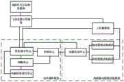
一种基于实际气动系数的风机转矩调控系统,包括风机叶片信息收集模块、气动系数计算模块、功率调控模块、上位机模块,功率调控模块包括相连的转矩调节单元、控制单元,风机叶片信息收集模块与气动系数计算模块连接,上位机模块、气动系数计算模块分别与转矩调节单元连接;A wind turbine torque control system based on actual aerodynamic coefficients, including a fan blade information collection module, an aerodynamic coefficient calculation module, a power control module, and a host computer module. The power control module includes a connected torque adjustment unit, a control unit, and fan blade information The collection module is connected with the aerodynamic coefficient calculation module, and the upper computer module and the aerodynamic coefficient calculation module are respectively connected with the torque adjustment unit;
风机叶片信息收集模块,用于识别风机叶片的几何形状数据;The fan blade information collection module is used to identify the geometric shape data of the fan blade;
气动系数计算模块,用于根据风机叶片的几何形状数据计算得到相应的实际气动系数;The aerodynamic coefficient calculation module is used to calculate and obtain the corresponding actual aerodynamic coefficient according to the geometric shape data of the fan blade;
上位机模块,用于输入风机功率改变需求量信息;The host computer module is used to input fan power change demand information;
转矩调节单元,基于实际气动系数、风机电机转速信息、风机功率改变需求量信息计算得到实际风机所需转矩;The torque adjustment unit calculates the actual torque required by the fan based on the actual aerodynamic coefficient, the fan motor speed information, and the fan power change demand information;
控制单元,基于实时风机所需转矩调整风机转矩。The control unit adjusts the torque of the fan based on the torque required by the fan in real time.
作为优选方案,气动系数计算模块根据风机叶片的几何形状数据计算得到相应的实际气动系数的具体方法为,将识别到的风机叶片几何形状切分为多个翼型截面薄片,将翼型截面形状与已知叶片库的截面形状进行比较,选取最接近的一组数据生成实际气动系数。As an optimal solution, the specific method for the aerodynamic coefficient calculation module to calculate the corresponding actual aerodynamic coefficient according to the geometric shape data of the fan blade is to cut the recognized geometric shape of the fan blade into a plurality of airfoil section slices, and divide the airfoil section shape into Compared with the cross-sectional shape of the known blade library, the closest set of data is selected to generate the actual aerodynamic coefficient.
作为优选方案,功率调控模块还包括相连的判断单元、电机转速调节单元,判断单元、电机转速调节单元分别与转矩调节单元连接;As a preferred solution, the power control module also includes a connected judging unit and a motor speed regulating unit, and the judging unit and the motor speed regulating unit are respectively connected to the torque regulating unit;
判断单元,用于判断转矩调节单元计算得到的实时风机所需转矩是否超过风机转矩可调节范围;A judging unit for judging whether the real-time required torque of the fan calculated by the torque adjustment unit exceeds the adjustable range of the fan torque;
电机转速调节单元,用于在计算得到的实时风机所需转矩超过风机转矩可调节范围时,对电机转速进行补偿,以得到补偿后电机转速;The motor speed adjustment unit is used to compensate the motor speed when the calculated real-time required torque of the fan exceeds the adjustable range of the fan torque, so as to obtain the compensated motor speed;
转矩调节单元,还基于实时气动系数、补偿后电机转速信息、风机功率改变需求量信息计算得到补偿后实时风机所需转矩。The torque adjustment unit is also based on the real-time aerodynamic coefficient, the motor speed information after compensation, and the fan power change demand information to calculate and obtain the torque required by the real-time fan after compensation.
作为优选方案,电机转速补偿的计算方法如下:As an optimal solution, the calculation method of motor speed compensation is as follows:
当转矩调节单元计算得到的实时风机所需转矩超过风机转矩可调节范围时,电机转速调节单元根据功率改变需求量、原电机转矩、由积分增益和比例增益决定的浆距控制器△β来计算一个电机转速变化量△ω;When the real-time required torque of the fan calculated by the torque adjustment unit exceeds the adjustable range of the fan torque, the motor speed adjustment unit changes the demand, the original motor torque, and the pitch controller determined by the integral gain and proportional gain according to the power △β to calculate a motor speed variation △ω;
通过根据实际气动系数计算得到的增益补偿系数KGS,对浆距控制器△β计算得到的电机转速变化量△ω进行优化,以得到优化后的电机转速变化量△ω';Through the gain compensation coefficient KGS calculated according to the actual aerodynamic coefficient, optimize the motor speed variation △ω calculated by the pitch controller △β to obtain the optimized motor speed variation △ω';
根据电机转速变化量△ω'、原电机转速ω得到补偿后电机转速ω0,将补偿后的电机转速ω0输入转矩调节单元,以计算得到补偿后的实时风机所需转矩。According to the motor speed variation △ω' and the original motor speed ω, the motor speed ω0 after compensation is obtained, and the compensated motor speed ω0 is input to the torque adjustment unit to calculate the real-time required torque of the fan after compensation.
作为优选方案,电机转速变化量△ω的计算公式为:As a preferred solution, the calculation formula of the motor speed variation △ω is:
△ω=KP+(KIKP)/s,△ω=KP +(KI KP )/s,
其中,KP为比例增益,KI为积分增益,s为积分增益因子。Among them, KP is the proportional gain, KI is the integral gain, and s is the integral gain factor.
作为优选方案,增益补偿系数KGS的计算公式为:As a preferred solution, the calculation formula of the gain compensation coefficient KGS is:

优化后的电机转速变化量△ω'计算公式为:The calculation formula of the optimized motor speed variation △ω' is:
△ω'=△ω×KGS,△ω'=△ω×KGS ,
即:Right now:

其中,
作为优选方案,系统还包括风机驱动模拟试验模块,风机驱动模拟试验模块包括电机传动单元、模拟试验路径;电机传动单元分别与控制单元、转矩调节单元连接,模拟试验路径与上位机模块连接;As a preferred solution, the system also includes a fan drive simulation test module, the fan drive simulation test module includes a motor transmission unit, a simulation test path; the motor transmission unit is connected to the control unit and the torque adjustment unit, and the simulation test path is connected to the host computer module;
电机传动单元,用于接收控制单元输出的补偿后的实时风机所需转矩进行工作,同时将电机转速信号回传至转矩调节单元以形成反馈控制;The motor transmission unit is used to receive the compensated real-time fan torque output by the control unit to work, and at the same time transmit the motor speed signal back to the torque adjustment unit to form feedback control;
模拟试验路径,用于接收电机传动模块传输的补偿后的实时风机所需转矩以模拟实际工况下风机电机在接收补偿后的实时风机所需转矩后在实际工况下的实际工作情况,并根据风机电机的实际工作情况获取实际功率,将实际功率传输至上位机模块;The simulation test path is used to receive the compensated real-time fan required torque transmitted by the motor drive module to simulate the actual working conditions of the fan motor under actual working conditions after receiving the compensated real-time fan required torque , and obtain the actual power according to the actual working conditions of the fan motor, and transmit the actual power to the host computer module;
上位机模块,用于根据人为输入的风机功率改变需求量信息、实际功率以验证补偿后的实时风机所需转矩的准确性。The upper computer module is used to change the demand information and actual power according to the artificially input fan power to verify the accuracy of the real-time fan required torque after compensation.
作为优选方案,模拟试验路径包括轴承模拟试验路径、齿轮模拟试验路径,轴承模拟试验路径用于模拟轴承类风机的实际工作情况,齿轮模拟试验路径用于模拟齿轮类风机的实际工作情况。As an optimal solution, the simulation test path includes a bearing simulation test path and a gear simulation test path. The bearing simulation test path is used to simulate the actual working conditions of the bearing-type fan, and the gear simulation test path is used to simulate the actual working condition of the gear-type fan.
作为优选方案,上位机模块,用于根据人为输入的风机功率改变需求量信息、实际功率的差值验证补偿后的实时风机所需转矩的准确性。As a preferred solution, the upper computer module is used to verify the accuracy of the real-time required torque of the fan after compensation according to the artificially input fan power change demand information and the difference of actual power.
作为优选方案,风机叶片信息收集模块采用激光雷达扫描识别风机叶片的几何形状数据。As a preferred solution, the fan blade information collection module uses laser radar scanning to identify the geometric shape data of the fan blade.
本发明的有益效果是:The beneficial effects of the present invention are:
1、本发明通过风机叶片信息收集模块,识别得到风机叶片的几何形状数据,根据风机叶片的几何形状数据计算得到相应的实际气动系数,控制单元输出的转矩融入实际气动系数,使输出的转矩更精确,达到的控制效果更精确。1. The present invention recognizes the geometric shape data of the fan blade through the fan blade information collection module, calculates the corresponding actual aerodynamic coefficient according to the geometric shape data of the fan blade, and integrates the torque output by the control unit into the actual aerodynamic coefficient, so that the output torque The torque is more precise, and the control effect achieved is more precise.
2、本发明设置融合真实气动系数的转矩调节单元,通过设置电机转速调节单元,在转矩调节单元计算得到的实时风机所需转矩超过风机转矩可调节范围时,对电机转速进行补偿,以得到满足功率改变需求所需的补偿后的实时风机所需转矩,使控制单元反应迅速,输出的转矩更加精确,增强系统的控制能力,同时改造成本低。2. The present invention sets a torque adjustment unit that integrates the real aerodynamic coefficient. By setting the motor speed adjustment unit, when the torque required by the real-time fan calculated by the torque adjustment unit exceeds the adjustable range of the fan torque, the motor speed is compensated. , in order to obtain the real-time torque required by the fan after compensation to meet the power change requirements, so that the control unit responds quickly, the output torque is more accurate, the control ability of the system is enhanced, and the transformation cost is low.
3、本发明的风机驱动模拟试验模块对控制单元输出的补偿后的实时风机所需转矩进行模拟试验,模拟试验路径将试验中的实际工作转矩传输至上位机模块,上位机模块通过比较根据人为输入的风机功率改变需求量信息、实际功率的差值,验证控制单元最后输出的补偿后的实时风机所需转矩的准确性,同时还为后续不同工况下的系统状态监测和故障诊断提供了技术支持。3. The fan drive simulation test module of the present invention performs a simulation test on the compensated real-time fan torque output by the control unit, and the simulation test path transmits the actual working torque in the test to the upper computer module, and the upper computer module compares According to the artificially input fan power, change the demand information and the difference between the actual power, verify the accuracy of the real-time fan torque required by the control unit after compensation, and also provide information for subsequent system status monitoring and failure under different working conditions. Diagnostics provides technical support.
4、本发明可实现人为输入的风机功率改变需求量信息、实际功率的误差在3%以内。4. The present invention can realize that the error of fan power change demand information and actual power input manually is within 3%.
附图说明Description of drawings
为了更清楚地说明本发明实施例或现有技术中的技术方案,下面将对实施例或现有技术描述中所需要使用的附图作简单地介绍,显而易见地,下面描述中的附图仅仅是本发明的一些实施例,对于本领域普通技术人员来讲,在不付出创造性劳动的前提下,还可以根据这些附图获得其他的附图。In order to more clearly illustrate the technical solutions in the embodiments of the present invention or the prior art, the following will briefly introduce the drawings that need to be used in the description of the embodiments or the prior art. Obviously, the accompanying drawings in the following description are only These are some embodiments of the present invention. Those skilled in the art can also obtain other drawings based on these drawings without creative work.
图1是一种基于实际气动系数的风机转矩调控系统的整体关系示意图。Fig. 1 is a schematic diagram of the overall relationship of a fan torque control system based on actual aerodynamic coefficients.
图2是电机转速调节单元和转矩调节单元计算补偿后的实时风机所需转矩的示意图。Fig. 2 is a schematic diagram of the real-time required torque of the fan calculated and compensated by the motor speed adjustment unit and the torque adjustment unit.
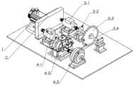
图3是风机驱动模拟试验模块的装配图。Figure 3 is an assembly diagram of the fan drive simulation test module.
图中的编码分别为:1、异步电机;2、齿轮传动系统;3、轴承模拟试验路径;3-1、扭矩传感器;3-2、轴承及轴承座;3-3、偏心盘;3-4、阶梯轴;4、齿轮模拟试验路径;4-1、扭矩传感器;4-2、齿轮减速器;4-3、磁粉制动器。The codes in the figure are: 1. Asynchronous motor; 2. Gear transmission system; 3. Bearing simulation test path; 3-1. Torque sensor; 3-2. Bearing and bearing housing; 3-3. Eccentric disc; 3- 4. Step shaft; 4. Gear simulation test path; 4-1. Torque sensor; 4-2. Gear reducer; 4-3. Magnetic powder brake.
具体实施方式Detailed ways
以下通过特定的具体实施例说明本发明的实施方式,本领域技术人员可由本说明书所揭露的内容轻易地了解本发明的其他优点与功效。本发明还可以通过另外不同的具体实施方式加以实施或应用,本说明书中的各项细节也可以基于不同观点与应用,在没有背离本发明的精神下进行各种修饰或改变。需说明的是,在不冲突的情况下,以下实施例及实施例中的特征可以相互组合。The implementation of the present invention is described below through specific specific examples, and those skilled in the art can easily understand other advantages and effects of the present invention from the content disclosed in this specification. The present invention can also be implemented or applied through other different specific implementation modes, and various modifications or changes can be made to the details in this specification based on different viewpoints and applications without departing from the spirit of the present invention. It should be noted that, in the case of no conflict, the following embodiments and features in the embodiments can be combined with each other.
参照图1,一种基于实际气动系数的风机转矩调控系统,其特征在于,包括风机叶片信息收集模块、气动系数计算模块、功率调控模块、上位机模块,功率调控模块包括相连的转矩调节单元、控制单元,风机叶片信息收集模块与气动系数计算模块连接,上位机模块、气动系数计算模块分别与转矩调节单元连接;Referring to Fig. 1, a fan torque control system based on actual aerodynamic coefficient is characterized in that it includes a fan blade information collection module, an aerodynamic coefficient calculation module, a power control module, and a host computer module, and the power control module includes a connected torque control module. The unit, the control unit, the fan blade information collection module are connected to the aerodynamic coefficient calculation module, and the upper computer module and the aerodynamic coefficient calculation module are respectively connected to the torque adjustment unit;
风机叶片信息收集模块,用于识别风机叶片的几何形状数据;The fan blade information collection module is used to identify the geometric shape data of the fan blade;
气动系数计算模块,用于根据风机叶片的几何形状数据计算得到相应的实际气动系数;The aerodynamic coefficient calculation module is used to calculate and obtain the corresponding actual aerodynamic coefficient according to the geometric shape data of the fan blade;
上位机模块,用于输入风机功率改变需求量信息;The host computer module is used to input fan power change demand information;
转矩调节单元,基于实际气动系数、风机电机转速信息、风机功率改变需求量信息计算得到实际风机所需转矩;The torque adjustment unit calculates the actual torque required by the fan based on the actual aerodynamic coefficient, the fan motor speed information, and the fan power change demand information;
控制单元,基于实时风机所需转矩调整风机转矩。The control unit adjusts the torque of the fan based on the torque required by the fan in real time.
进一步,本实施例中,风机叶片形状识别模块采用激光雷达,雷达的精度为在100m扫描距离上具有2.5mm的3D位置精度;雷达的数量为三个,放置位置设置在距离风力发电机100米至115米的位置,确保收集数据具有良好的入射角。扫描的具体方式为,首先暂停风机工作,以获得精确的叶片几何形状,其次将某个叶片中线与6点钟位置重合,并且标记,然后扫描该位置叶片,最后扫描其他两个叶片,确保数据的准确性。雷达每次扫描10到15分钟,每次设置收集大约120万点;扫描时使用典型气动模型,即每次扫描叶片12个部位,以满足后续分析的要求。Further, in this embodiment, the wind turbine blade shape recognition module adopts laser radar, and the accuracy of the radar is 2.5mm 3D position accuracy at a scanning distance of 100m; the number of radars is three, and the placement position is set at 100 meters away from the wind turbine To the position of 115 meters, ensure that the collected data has a good angle of incidence. The specific way of scanning is to first suspend the work of the fan to obtain the precise geometry of the blade, secondly to coincide the midline of a certain blade with the 6 o’clock position, and mark it, then scan the blade at this position, and finally scan the other two blades to ensure that the data accuracy. The radar scans for 10 to 15 minutes each time, and each setting collects about 1.2 million points; a typical aerodynamic model is used for scanning, that is, 12 parts of the blade are scanned each time to meet the requirements of subsequent analysis.
进一步,气动系数计算模块根据风机叶片的几何形状数据计算得到相应的实际气动系数的具体方法为,将识别到的风机叶片几何形状切分为12个翼型截面薄片,将翼型截面形状与已知叶片库的截面形状进行比较,选取最接近的一组数据生成实际气动系数。Furthermore, the specific method for the aerodynamic coefficient calculation module to calculate the corresponding actual aerodynamic coefficient according to the geometric shape data of the fan blade is to divide the recognized geometric shape of the fan blade into 12 airfoil section slices, and compare the airfoil section shape with the already Compare the cross-sectional shapes of the known blade library, and select the closest set of data to generate the actual aerodynamic coefficient.
进一步,功率调控模块还包括相连的判断单元、电机转速调节单元,判断单元、电机转速调节单元分别与转矩调节单元连接;Further, the power control module also includes a connected judging unit and a motor speed regulating unit, and the judging unit and the motor speed regulating unit are respectively connected to the torque regulating unit;
判断单元,用于判断转矩调节单元计算得到的实时风机所需转矩是否超过风机转矩可调节范围;A judging unit for judging whether the real-time required torque of the fan calculated by the torque adjustment unit exceeds the adjustable range of the fan torque;
电机转速调节单元,用于在计算得到的实时风机所需转矩超过风机转矩可调节范围时,对电机转速进行补偿,以得到补偿后电机转速;The motor speed adjustment unit is used to compensate the motor speed when the calculated real-time required torque of the fan exceeds the adjustable range of the fan torque, so as to obtain the compensated motor speed;
转矩调节单元,还基于实时气动系数、补偿后电机转速信息、风机功率改变需求量信息计算得到补偿后实时风机所需转矩。The torque adjustment unit is also based on the real-time aerodynamic coefficient, the motor speed information after compensation, and the fan power change demand information to calculate and obtain the torque required by the real-time fan after compensation.
进一步,电机转速调节单元和转矩调节单元的关系参照图2所示,电机转速补偿的计算方法如下:Further, the relationship between the motor speed adjustment unit and the torque adjustment unit is shown in Figure 2, and the calculation method of the motor speed compensation is as follows:
当转矩调节单元计算得到的实时风机所需转矩超过风机转矩可调节范围时,电机转速调节单元根据功率改变需求量、原电机转矩、由积分增益和比例增益决定的浆距控制器△β来计算一个电机转速变化量△ω;When the real-time required torque of the fan calculated by the torque adjustment unit exceeds the adjustable range of the fan torque, the motor speed adjustment unit changes the demand, the original motor torque, and the pitch controller determined by the integral gain and proportional gain according to the power △β to calculate a motor speed variation △ω;
通过根据实际气动系数计算得到的增益补偿系数KGS,对浆距控制器△β计算得到的电机转速变化量△ω进行优化,以得到优化后的电机转速变化量△ω';Through the gain compensation coefficient KGS calculated according to the actual aerodynamic coefficient, optimize the motor speed variation △ω calculated by the pitch controller △β to obtain the optimized motor speed variation △ω';
根据电机转速变化量△ω'、原电机转速ω得到补偿后电机转速ω0,将补偿后的电机转速ω0输入转矩调节单元,以计算得到补偿后的实时风机所需转矩。According to the motor speed variation △ω' and the original motor speed ω, the motor speed ω0 after compensation is obtained, and the compensated motor speed ω0 is input to the torque adjustment unit to calculate the real-time required torque of the fan after compensation.
进一步,电机转速变化量△ω的计算公式为:Further, the calculation formula of the motor speed variation △ω is:
△ω=KP+(KIKP)/s,△ω=KP +(KI KP )/s,
其中,KP为比例增益,KI为积分增益,s为积分增益因子。Among them, KP is the proportional gain, KI is the integral gain, and s is the integral gain factor.
进一步,增益补偿系数KGS的计算公式为:Further, the calculation formula of the gain compensation coefficient KGS is:

优化后的电机转速变化量△ω'计算公式为:The calculation formula of the optimized motor speed variation △ω' is:
△ω'=△ω×KGS,△ω'=△ω×KGS ,
即:Right now:

其中,
具体地:specifically:
为了使闭环系统保持稳定,将浆距控制器△β的变化率设置为低于0.5度/秒,为了保证△ω的误差不要太大将浆距控制器△β的带宽设置为大于1转/秒。In order to keep the closed-loop system stable, set the rate of change of the pitch controller △β to be lower than 0.5 degrees/second, and to ensure that the error of △ω is not too large, set the bandwidth of the pitch controller △β to be greater than 1 revolution/second .
进一步,系统还包括风机驱动模拟试验模块,风机驱动模拟试验模块包括电机传动单元、模拟试验路径;电机传动单元分别与控制单元、转矩调节单元连接,模拟试验路径与上位机模块连接;Further, the system also includes a fan drive simulation test module. The fan drive simulation test module includes a motor drive unit and a simulation test path; the motor drive unit is connected to the control unit and the torque adjustment unit respectively, and the simulation test path is connected to the upper computer module;
电机传动单元,用于接收控制单元输出的补偿后的实时风机所需转矩进行工作,同时将电机转速信号回传至转矩调节单元以形成反馈控制;The motor transmission unit is used to receive the compensated real-time fan torque output by the control unit to work, and at the same time transmit the motor speed signal back to the torque adjustment unit to form feedback control;
模拟试验路径,用于接收电机传动模块传输的补偿后的实时风机所需转矩以模拟实际工况下风机电机在接收补偿后的实时风机所需转矩后在实际工况下的实际工作情况,并根据风机电机的实际工作情况获取实际功率,将实际功率传输至上位机模块;The simulation test path is used to receive the compensated real-time fan required torque transmitted by the motor drive module to simulate the actual working conditions of the fan motor under actual working conditions after receiving the compensated real-time fan required torque , and obtain the actual power according to the actual working conditions of the fan motor, and transmit the actual power to the host computer module;
上位机模块,用于根据人为输入的风机功率改变需求量信息、实际功率以验证补偿后的实时风机所需转矩的准确性。The upper computer module is used to change the demand information and actual power according to the artificially input fan power to verify the accuracy of the real-time fan required torque after compensation.
进一步,模拟试验路径包括轴承模拟试验路径、齿轮模拟试验路径,轴承模拟试验路径用于模拟轴承类风机的实际工作情况,齿轮模拟试验路径用于模拟齿轮类风机的实际工作情况。Further, the simulation test path includes a bearing simulation test path and a gear simulation test path, the bearing simulation test path is used to simulate the actual working conditions of the bearing-type fan, and the gear simulation test path is used to simulate the actual working conditions of the gear-type fan.
具体地:specifically:
参照图3,本实施例中,电机传动单元包括异步电机1、齿轮传动系统2,齿轮传动系统将转矩分为两条模拟试验路径,两条模拟试验路径为轴承模拟试验路径3、齿轮模拟试验路径4。轴承模拟试验路径3包括扭矩传感器3-1、轴承及轴承座3-2、偏心盘3-3、阶梯轴3-4;齿轮模拟试验路径包括扭矩传感器4-1、齿轮减速器4-2、磁粉制动器4-3;偏心盘3-3和磁粉制动器4-3具有调整试验系统扭矩的作用。With reference to Fig. 3, in the present embodiment, motor transmission unit comprises asynchronous motor 1,
本实施例中,两条模拟实验路径的具体参数为:In this embodiment, the specific parameters of the two simulated experiment paths are:
扭矩传感器3-1、扭矩传感器4-1的参数为:转矩量程为20N.m,转速量程为6000rpm,线数为60线;磁粉制动器4-3的参数为:定格转矩为2.5(25)kgf/m(N-m),功率为30W;偏心盘3-3在圆周阵列分布24个螺纹孔,可以通过添加特制砝码实现扭矩的改变,以增强实验的灵活性。The parameters of torque sensor 3-1 and torque sensor 4-1 are: the torque range is 20N.m, the speed range is 6000rpm, and the number of lines is 60 lines; the parameters of magnetic powder brake 4-3 are: the rated torque is 2.5 (25 )kgf/m(N-m), the power is 30W; the eccentric disc 3-3 has 24 threaded holes distributed in a circular array, and the torque can be changed by adding special weights to enhance the flexibility of the experiment.
进一步,上位机模块,用于根据人为输入的风机功率改变需求量信息、实际功率的差值验证补偿后的实时风机所需转矩的准确性。Further, the upper computer module is used to verify the accuracy of the real-time required torque of the fan after compensation according to the artificially input fan power change demand information and the difference of the actual power.
具体地:specifically:
上位机子系统包括主线程、通信线程,主线程用于图形界面的构建、同步操作员的操作、处理信息并与气动系数计算模块、转矩调节单元进行通信;通信线程用于接收风机驱动模拟试验模块输出的实时转矩,并把数据发送给主线程;上位机模块的主线程、通信线程通过信息传输来实现通信,以实现上位机子系统的快速响应。The host computer subsystem includes a main thread and a communication thread. The main thread is used to construct a graphical interface, synchronize operator operations, process information and communicate with the aerodynamic coefficient calculation module and torque adjustment unit; the communication thread is used to receive fan drive simulation tests The real-time torque output by the module, and send the data to the main thread; the main thread and communication thread of the host computer module realize communication through information transmission, so as to realize the rapid response of the host computer subsystem.
以上所述的实施例仅仅是对本发明的优选实施方式进行描述,并非对本发明的范围进行限定,在不脱离本发明设计精神的前提下,本领域普通技术人员对本发明的技术方案作出的各种变形和改进,均应落入本发明的保护范围内。The above-mentioned embodiments are only descriptions of preferred implementations of the present invention, and are not intended to limit the scope of the present invention. Variations and improvements should fall within the protection scope of the present invention.
Claims (10)
Translated fromChinese


Priority Applications (1)
| Application Number | Priority Date | Filing Date | Title |
|---|---|---|---|
| CN202211738046.4ACN116044656B (en) | 2022-12-31 | 2022-12-31 | Fan torque regulation and control system based on actual pneumatic coefficient |
Applications Claiming Priority (1)
| Application Number | Priority Date | Filing Date | Title |
|---|---|---|---|
| CN202211738046.4ACN116044656B (en) | 2022-12-31 | 2022-12-31 | Fan torque regulation and control system based on actual pneumatic coefficient |
Publications (2)
| Publication Number | Publication Date |
|---|---|
| CN116044656Atrue CN116044656A (en) | 2023-05-02 |
| CN116044656B CN116044656B (en) | 2025-06-27 |
Family
ID=86112695
Family Applications (1)
| Application Number | Title | Priority Date | Filing Date |
|---|---|---|---|
| CN202211738046.4AActiveCN116044656B (en) | 2022-12-31 | 2022-12-31 | Fan torque regulation and control system based on actual pneumatic coefficient |
Country Status (1)
| Country | Link |
|---|---|
| CN (1) | CN116044656B (en) |
Citations (7)
| Publication number | Priority date | Publication date | Assignee | Title |
|---|---|---|---|---|
| CN202768249U (en)* | 2012-08-03 | 2013-03-06 | 国电联合动力技术有限公司 | Wind generation set control system based on pneumatic torque calculation model |
| CN103604601A (en)* | 2013-10-21 | 2014-02-26 | 浙江大学 | Fault diagnosis experiment platform based on wind power gearbox working condition simulation |
| US20140097619A1 (en)* | 2012-09-28 | 2014-04-10 | Acciona Windpower, S.A. | Wind turbine control method |
| US20150086362A1 (en)* | 2013-09-23 | 2015-03-26 | General Electric Company | Control system and method for mitigating rotor imbalance on a wind turbine |
| CN106870282A (en)* | 2017-03-30 | 2017-06-20 | 湘电风能有限公司 | Wind turbines load shedding control method under a kind of fitful wind |
| CN107795434A (en)* | 2017-10-23 | 2018-03-13 | 北京金风科创风电设备有限公司 | Control method, device and equipment of wind driven generator and storage medium |
| CN115085607A (en)* | 2020-09-04 | 2022-09-20 | 湖南工业大学 | Load torque compensation method for permanent magnet synchronous motor |
- 2022
- 2022-12-31CNCN202211738046.4Apatent/CN116044656B/enactiveActive
Patent Citations (7)
| Publication number | Priority date | Publication date | Assignee | Title |
|---|---|---|---|---|
| CN202768249U (en)* | 2012-08-03 | 2013-03-06 | 国电联合动力技术有限公司 | Wind generation set control system based on pneumatic torque calculation model |
| US20140097619A1 (en)* | 2012-09-28 | 2014-04-10 | Acciona Windpower, S.A. | Wind turbine control method |
| US20150086362A1 (en)* | 2013-09-23 | 2015-03-26 | General Electric Company | Control system and method for mitigating rotor imbalance on a wind turbine |
| CN103604601A (en)* | 2013-10-21 | 2014-02-26 | 浙江大学 | Fault diagnosis experiment platform based on wind power gearbox working condition simulation |
| CN106870282A (en)* | 2017-03-30 | 2017-06-20 | 湘电风能有限公司 | Wind turbines load shedding control method under a kind of fitful wind |
| CN107795434A (en)* | 2017-10-23 | 2018-03-13 | 北京金风科创风电设备有限公司 | Control method, device and equipment of wind driven generator and storage medium |
| CN115085607A (en)* | 2020-09-04 | 2022-09-20 | 湖南工业大学 | Load torque compensation method for permanent magnet synchronous motor |
Non-Patent Citations (1)
| Title |
|---|
| 张茶花: "风力机叶片气动性能分析及优化设计", 《中国优秀硕士学位论文全文数据库工程科技Ⅱ辑》, no. 2, 15 December 2013 (2013-12-15)* |
Also Published As
| Publication number | Publication date |
|---|---|
| CN116044656B (en) | 2025-06-27 |
Similar Documents
| Publication | Publication Date | Title |
|---|---|---|
| EP2169218B1 (en) | System and method for estimating wind condition for wind turbines | |
| CN103758700B (en) | A kind of calibrate the blower fan method to windage losses | |
| CN111472930B (en) | Evolutionary wind speed calculation method and feedforward unified pitch control method based on the method | |
| US11668284B2 (en) | Method of determining an induction factor for a wind turbine equipped with a lidar sensor | |
| WO2020097979A1 (en) | Wind farm control parameter optimization method and system | |
| EP2120204A1 (en) | Method and system to quantify performance of a power generating system | |
| CN107844095B (en) | Master control program simulation test system and method applied to wind power generation | |
| CN107664096B (en) | Yaw wind control method, device and system | |
| Jang et al. | Performance evaluation and validation of H-darrieus small vertical axis wind turbine | |
| US11421651B2 (en) | Method of determining wind direction by means of a LiDAR sensor | |
| CN118775150A (en) | Method for controlling a wind farm using optimization methods | |
| CN116720437A (en) | Modeling method, system, terminal and medium for clearance distance of wind turbine generator blade | |
| EP4208641B1 (en) | Method and controller arrangement for operating a wind turbine farm | |
| CN113252938A (en) | Method for determining the wind speed in the rotor plane of a wind turbine | |
| CN116044656A (en) | A fan torque control system based on actual aerodynamic coefficient | |
| GB2555010B (en) | Determining loads on a wind turbine | |
| CN114528648A (en) | Method for determining wind speed in a rotor plane of a wind turbine | |
| Yi et al. | Airfoil design for vertical axis wind turbine operating at variable tip speed ratios | |
| CN112861301A (en) | Wind power plant theoretical power intelligent calculation method based on real-time data of fans | |
| CN214836884U (en) | Device for measuring power characteristics of offshore wind turbine generator system | |
| CN113279904B (en) | Pitch angle optimizing method and device for maximum power tracking of wind turbine generator | |
| CN118757317B (en) | A feedforward unified pitch control method and device based on wind evolution modeling | |
| US11578701B2 (en) | Method of determining an induction factor between a measurement plane and the rotor plane of a wind turbine | |
| CN117907635A (en) | Correcting system and method for wind speed and wind direction of wind power plant unit | |
| CN113484051A (en) | Real-time thermal equivalent simulation method and system for airborne system |
Legal Events
| Date | Code | Title | Description |
|---|---|---|---|
| PB01 | Publication | ||
| PB01 | Publication | ||
| SE01 | Entry into force of request for substantive examination | ||
| SE01 | Entry into force of request for substantive examination | ||
| GR01 | Patent grant | ||
| GR01 | Patent grant |