CN116026499A - Pressure sensing device and manufacturing method thereof - Google Patents
Pressure sensing device and manufacturing method thereofDownload PDFInfo
- Publication number
- CN116026499A CN116026499ACN202111240334.2ACN202111240334ACN116026499ACN 116026499 ACN116026499 ACN 116026499ACN 202111240334 ACN202111240334 ACN 202111240334ACN 116026499 ACN116026499 ACN 116026499A
- Authority
- CN
- China
- Prior art keywords
- electrode
- flexible substrate
- sensing device
- pressure
- pressure sensing
- Prior art date
- Legal status (The legal status is an assumption and is not a legal conclusion. Google has not performed a legal analysis and makes no representation as to the accuracy of the status listed.)
- Granted
Links
Images


Landscapes
- Measuring Fluid Pressure (AREA)
- Force Measurement Appropriate To Specific Purposes (AREA)
Abstract
Translated fromChinese
Description
Translated fromChinese技术领域technical field
本发明是有关于一种压力传感装置与其制造方法。The invention relates to a pressure sensing device and a manufacturing method thereof.
背景技术Background technique
压力传感装置可感测到使用者施加在其上的压力,借由压力产生的形变转换为电信号或者其他所需形式的信息输出。感力传感装置输出的信号可触发反馈模块,进而提供使用者直观的感受,举例来说,触摸板可依据使用者不同的施压力度而提供不同的震动反馈。若是压力感测装置无法提供准确的信号,可能使反馈模块无法提供正确的反馈,则会造成使用者感知错误或操作不便。The pressure sensing device can sense the pressure exerted by the user on it, and convert the deformation generated by the pressure into an electrical signal or other required forms of information output. The signal output by the force sensing device can trigger the feedback module, thereby providing the user with an intuitive experience. For example, the touch panel can provide different vibration feedbacks according to different pressure levels of the user. If the pressure sensing device cannot provide accurate signals, the feedback module may not be able to provide correct feedback, which will cause user perception errors or inconvenient operation.
因此,各业者极力提升压力传感装置及其工艺的精度以确保输出准确的信号,提升压力感测装置的感测准确度。Therefore, various industries strive to improve the precision of the pressure sensing device and its process to ensure accurate output signals and improve the sensing accuracy of the pressure sensing device.
发明内容Contents of the invention
根据本发明的一些实施例,一种压力传感装置包括第一软性基材、设置在第一软性基材上的感压材料及设置在感压材料上的第二软性基材。第二软性基材具有面向感压材料的第一表面、相对于第一表面的第二表面、以及延伸至第一表面和第二表面的开口。压力传感装置还包括电极组,设置在开口中并从开口延伸至第一表面与第二表面,其中电极组电性连接感压材料并具有第一电极及第二电极。第一电极覆盖开口的部分内表面、部分第一表面与部分第二表面。第二电极覆盖开口的部分内表面、部分第一表面与部分第二表面,其中第二电极与第一电极彼此相对配置且分开。According to some embodiments of the present invention, a pressure sensing device includes a first flexible substrate, a pressure-sensitive material disposed on the first flexible substrate, and a second flexible substrate disposed on the pressure-sensitive material. The second flexible substrate has a first surface facing the pressure-sensitive material, a second surface opposite to the first surface, and an opening extending to the first surface and the second surface. The pressure sensing device further includes an electrode set disposed in the opening and extending from the opening to the first surface and the second surface, wherein the electrode set is electrically connected to the pressure-sensitive material and has a first electrode and a second electrode. The first electrode covers part of the inner surface, part of the first surface and part of the second surface of the opening. The second electrode covers part of the inner surface, part of the first surface and part of the second surface of the opening, wherein the second electrode and the first electrode are arranged opposite to each other and separated from each other.
在一些实施例中,在从第二表面观看压力传感装置的俯视图中,第一电极和第二电极呈现镜射对称。In some embodiments, in a plan view of the pressure sensing device viewed from the second surface, the first electrode and the second electrode exhibit mirror symmetry.
在一些实施例中,第一电极具有第一凹面,而第二电极具有第二凹面,第一凹面与第二凹面彼此面对面。In some embodiments, the first electrode has a first concave surface, and the second electrode has a second concave surface, and the first concave surface and the second concave surface face each other.
在一些实施例中,感压材料包括弹性树脂及数个导电材料,其中导电材料分布在弹性树脂内。In some embodiments, the pressure-sensitive material includes elastic resin and several conductive materials, wherein the conductive material is distributed in the elastic resin.
在一些实施例中,导电材料包括银。In some embodiments, the conductive material includes silver.
在一些实施例中,导电材料还包括锡或铋。In some embodiments, the conductive material also includes tin or bismuth.
在一些实施例中,电极组的材料包括锡或银。In some embodiments, the material of the electrode set includes tin or silver.
在一些实施例中,设置在第二软性基材的第一表面上的电极组直接接触感压材料。In some embodiments, the electrode set disposed on the first surface of the second flexible substrate directly contacts the pressure-sensitive material.
在一些实施例中,压力传感装置进一步包括保护层,填满于第二软性基材的开口中,并分布在第一电极与第二电极之间。In some embodiments, the pressure sensing device further includes a protective layer filling the opening of the second flexible substrate and distributed between the first electrode and the second electrode.
在一些实施例中,设置开口的内表面上的电极组直接接触保护层。In some embodiments, the electrode set disposed on the inner surface of the opening directly contacts the protective layer.
根据本发明的一些实施例,一种制造压力传感装置的方法包括提供第一软性基材、设置感压材料在第一软性基材上、提供具有第一表面及相对于第一表面的第二表面的第二软性基材、以及形成开口在第二软性基材中。开口延伸至第一表面和第二表面。制造压力传感装置的方法还包括形成导电层在开口的内表面上及第一表面上,其中在从第二表面观看而成的俯视图中导电层具有连续边缘。制造压力传感装置的方法还包括移除导电层的第一部分与相对于第一部分的第二部分,使得导电层的连续边缘断开而分离出第一电极和第二电极。制造压力传感装置的方法还包括压合第一软性基材与第二软性基材,使得感压材料电性连接第一电极与第二电极,其中感压材料介在第一软性基材与第二软性基材之间。According to some embodiments of the present invention, a method of manufacturing a pressure sensing device includes providing a first flexible substrate, disposing a pressure-sensitive material on the first flexible substrate, providing a A second flexible base material on the second surface of the second flexible base material, and openings are formed in the second flexible base material. The opening extends to the first surface and the second surface. The method of manufacturing the pressure sensing device further includes forming a conductive layer on the inner surface of the opening and on the first surface, wherein the conductive layer has a continuous edge in a plan view viewed from the second surface. The method of manufacturing the pressure sensing device further includes removing the first portion of the conductive layer and the second portion opposite the first portion such that a continuous edge of the conductive layer is broken to separate the first electrode and the second electrode. The method for manufacturing the pressure sensing device further includes pressing the first flexible substrate and the second flexible substrate so that the pressure-sensitive material is electrically connected to the first electrode and the second electrode, wherein the pressure-sensitive material is interposed between the first flexible substrate and the second electrode. material and the second soft substrate.
在一些实施例中,在移除第一部分与第二部分之后,在从第二表面观看而成的俯视图中,第一电极和第二电极呈现镜射对称。In some embodiments, after removing the first portion and the second portion, the first electrode and the second electrode exhibit mirror symmetry in a plan view viewed from the second surface.
在一些实施例中,形成导电层包括使用电镀工艺。In some embodiments, forming the conductive layer includes using an electroplating process.
在一些实施例中,制造压力传感装置的方法进一步包括在压合第一软性基材与第二软性基材之前形成银层或锡层在第一电极和第二电极上。In some embodiments, the method of manufacturing the pressure sensing device further includes forming a silver layer or a tin layer on the first electrode and the second electrode before laminating the first flexible substrate and the second flexible substrate.
在一些实施例中,压合第一软性基材与第二软性基材的压合温度在摄氏180度和摄氏260度的范围之间。In some embodiments, the lamination temperature for laminating the first flexible substrate and the second flexible substrate is between 180 degrees Celsius and 260 degrees Celsius.
在一些实施例中,压合第一软性基材与第二软性基材使得第一电极与第二电极皆直接接触感压材料。In some embodiments, the first flexible substrate and the second flexible substrate are pressed together so that both the first electrode and the second electrode directly contact the pressure-sensitive material.
在一些实施例中,制造压力传感装置的方法进一步包括形成保护层在第二软性基材上,其中保护层分布在第一电极与第二电极之间。In some embodiments, the method of manufacturing a pressure sensing device further includes forming a protective layer on the second flexible substrate, wherein the protective layer is distributed between the first electrode and the second electrode.
本发明的实施例提供压力装置与其制造方法。借由压合具有感压材料的第一软性基材及具有电极组的第二软性基材以及借由同一孔洞而制成电极组,提升压力感测装置的感测准确度。Embodiments of the present invention provide pressure devices and methods of manufacturing the same. The sensing accuracy of the pressure sensing device is improved by laminating the first flexible base material with the pressure-sensitive material and the second flexible base material with the electrode group and forming the electrode group through the same hole.
附图说明Description of drawings
阅读以下实施方法时搭配附图以清楚理解本发明的观点。应注意的是,根据业界的标准做法,各种特征并未按照比例绘制。事实上,为了能清楚地讨论,各种特征的尺寸可能任意地放大或缩小。再者,相同的附图标记表示相同的元件。When reading the following implementation methods with accompanying drawings, the viewpoints of the present invention can be clearly understood. It should be noted that, in accordance with the standard practice in the industry, various features are not drawn to scale. In fact, the dimensions of the various features may be arbitrarily expanded or reduced for clarity of discussion. Again, the same reference numerals denote the same elements.
图1A、图2A、图3A、图4A、图5A、图6A和图7A为依据本发明一些实施例绘示压力传感装置在各个制造阶段的俯视图。1A , 2A, 3A, 4A, 5A, 6A and 7A are top views illustrating various manufacturing stages of a pressure sensing device according to some embodiments of the present invention.
图1B、图2B、图3B、图4B、图5B、图6B和图7B为依据本发明一些实施例绘示压力传感装置在各个制造阶段沿俯视图中的剖线A-A的截面图。1B , 2B, 3B, 4B, 5B, 6B and 7B are cross-sectional views along the section line A-A in the top view illustrating various manufacturing stages of the pressure sensing device according to some embodiments of the present invention.
具体实施方式Detailed ways
当诸如层、膜、区域或基材的元件被称为在另一元件“上”或“连接到”另一元件时,其可以直接在另一元件上或与另一元件连接,或者中间元件可以也存在。相反,当元件被称为“直接在另一元件上”或“直接连接到”另一元件时,不存在中间元件。如本文所使用的,“连接”可以指物理及/或电性连接。再者,“电性连接”或“耦合”可为二元件间存在其它元件。When an element such as a layer, film, region, or substrate is referred to as being "on" or "connected to" another element, it can be directly on or connected to the other element or intervening elements. can also exist. In contrast, when an element is referred to as being "directly on" or "directly connected to" another element, there are no intervening elements present. As used herein, "connected" may refer to physical and/or electrical connection. Furthermore, "electrically connected" or "coupled" may mean that other elements exist between two elements.
此外,诸如“下”或“底部”和“上”或“顶部”的相对术语可在本文中用于描述一个元件与另一元件的关系,如图所示。应当理解,相对术语旨在包括除了图中所示的方位之外的装置的不同方位。例如,如果一个附图中的装置翻转,则被描述为在其他元件的“下”侧的元件将被定向在其他元件的“上”侧。因此,示例性术语“下”可以包括“下”和“上”的取向,取决于附图的特定取向。类似地,如果一个附图中的装置翻转,则被描述为在其它元件“下方”或“下方”的元件将被定向为在其它元件“上方”。因此,示例性术语“下面”或“下面”可以包括上方和下方的取向。Additionally, relative terms such as "lower" or "bottom" and "upper" or "top" may be used herein to describe one element's relationship to another element as shown in the figures. It will be understood that relative terms are intended to encompass different orientations of the device in addition to the orientation depicted in the figures. For example, if the device in one of the figures is turned over, elements described as being on the "lower" side of other elements would then be oriented on "upper" sides of the other elements. Thus, the exemplary term "below" can encompass both an orientation of "below" and "upper," depending on the particular orientation of the drawing. Similarly, if the device in one of the figures is turned over, elements described as "below" or "beneath" other elements would then be oriented "above" the other elements. Thus, the exemplary terms "below" or "beneath" can encompass both an orientation of above and below.
本文使用的“约”、“近似”、或“大致上”包括所述值和在本领域普通技术人员确定的特定值的可接受的偏差范围内的平均值,考虑到所讨论的测量和与测量相关的误差的特定数量(即,测量系统的限制)。例如,“约”可以表示在所述值的一个或多个标准偏差内。As used herein, "about," "approximately," or "substantially" includes stated values and averages within acceptable deviations from a particular value as determined by one of ordinary skill in the art, taking into account the measurements in question and the relative A specific amount of measurement-related error (ie, a limitation of the measurement system). For example, "about" can mean within one or more standard deviations of the stated value.
除非另有定义,本文使用的所有术语(包括技术和科学术语)具有与本发明所属领域的普通技术人员通常理解的相同的含义。将进一步理解的是,诸如在通常使用的字典中定义的那些术语应当被解释为具有与它们在相关技术和本发明的上下文中的含义一致的含义,并且将不被解释为理想化的或过度正式的意义,除非本文中明确地这样定义。Unless otherwise defined, all terms (including technical and scientific terms) used herein have the same meaning as commonly understood by one of ordinary skill in the art to which this invention belongs. It will be further understood that terms such as those defined in commonly used dictionaries should be interpreted to have meanings consistent with their meanings in the context of the relevant art and the present invention, and will not be interpreted as idealized or excessive formal meaning, unless expressly so defined herein.
压力传感装置可感测到施加在其上的压力,借由压力产生的形变转换为电信号或者其他所需形式的信息输出。因此,通过压力传感装置的电信号变化可得出外界施加的压力大小的关系(例如,线性关系)。若电信号受到干扰将使压力大小判断受到影响,导致压力传导装置的感测精准度下降。因此,本发明的实施例提供一种压力传感装置与其制造方法来提升压力传感装置及其工艺的精度以确保输出准确的信号,提升压力感测装置的感测准确度。The pressure sensing device can sense the pressure exerted on it, and convert the deformation generated by the pressure into an electrical signal or other required forms of information output. Therefore, the relationship (for example, linear relationship) of the pressure applied by the outside can be obtained through the change of the electrical signal of the pressure sensing device. If the electrical signal is disturbed, the judgment of the pressure will be affected, resulting in a decrease in the sensing accuracy of the pressure transmission device. Therefore, the embodiments of the present invention provide a pressure sensing device and its manufacturing method to improve the precision of the pressure sensing device and its process so as to ensure accurate output signals and improve the sensing accuracy of the pressure sensing device.
应注意的是,除非有额外说明,当以下实施例绘示或描述成一系列的操作或事件时,这些操作或事件的描述顺序不应受到限制。例如,部分操作或事件可采取与本发明不同的顺序、部分操作或事件可同时发生、部分操作或事件可以不须采用、及/或部分操作或事件可重复进行。并且,实际的工艺可能须各步骤之前、过程中、或之后进行额外的操作以完整形成压力传导装置。因此,本发明可能将简短地说明其中一些额外的操作。It should be noted that, unless otherwise specified, when the following embodiments are shown or described as a series of operations or events, the description order of these operations or events should not be limited. For example, some operations or events may be performed in a different order than in the present invention, some operations or events may occur concurrently, some operations or events may not be required, and/or some operations or events may be repeated. Also, the actual process may require additional operations before, during, or after each step to completely form the pressure transmission device. Therefore, the present invention may briefly describe some of these additional operations.
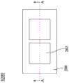
请同时参照图1A和图1B,图1A为依据本发明一些实施例绘示压力传感装置在其中一个制造阶段的俯视图,图1B为依据本发明一些实施例绘示压力传感装置沿图1A中的剖线A-A的截面图。首先,在步骤S100中,提供第一软性基材100和感压材料102,其中感压材料102设置在第一软性基材100上。Please refer to FIG. 1A and FIG. 1B at the same time. FIG. 1A is a top view of a pressure sensing device in one of the manufacturing stages according to some embodiments of the present invention, and FIG. 1B is a top view of a pressure sensing device according to some embodiments of the present invention along FIG. 1A Sectional view of section line A-A in. First, in step S100 , a first
第一软性基材100材料可包括可挠性的聚合物材料,例如聚酰亚胺(polyimide,PI)、热可塑性聚酰亚胺(thermoplastic polyimide,TPI)、聚对苯二甲酸乙二醇酯(polyethylene terephthalate,PET)、聚萘二甲酸乙二醇酯(polythylene naphthalate,PEN)、聚氨酯(polyurethane,PU)、热塑性聚氨酯(thermoplastic polyurethane,TPU)、其它合适材料、上述的衍生物、或上述材料的任意组合。举例来说,第一软性基材100的材料可包括热可塑性聚酰亚胺(TPI)。The material of the first
感压材料102的材料可包括弹性树脂(未绘出)和数个导电材料(未绘出),其中弹性树脂可作为绝缘基体,而导电材料分布在弹性树脂内以提供电性传导的作用。感压材料102的弹性树脂可包括聚二甲基硅氧烷(polydimethylsiloxane,PDMS)、热塑性聚氨酯(thermoplastic polyurethane,TPU)、聚酯(polyester)树脂、环氧(epoxy)树脂、硅胶(silicon)树脂、或其他合适的材料、或上述材料的任意组合。举例来说,感压材料102的弹性树脂可包括PDMS。在一些实施例中,在形成感压材料102的材料中弹性树脂在15wt%(重量百分比)至20wt%之间。在一些实施例中,弹性树脂的拉伸率在5%至50%的范围之间。The pressure-
感压材料102的导电材料可包括金属,例如银导电粉体、导电纳米银线、多支状银、碳导电粉体、导电纳米碳管、镍导电粉体、银包铝导电粉体、银包铜导电粉体、银包镍导电粉体、银包玻璃导电粉体、其他合适的金属、或上述材料的任意组合。感压材料102的导电材料还可包括氧化物,例如氧化锌粉体、氧化铟锡粉体、二氧化钌粉体、其他合适的材料、或上述材料的任意组合。举例来说,感压材料102的导电材料可包括银,例如银导电粉体、导电纳米银线、多支状银、银包铜导电粉体等。导电材料可进一步包括锡或铋。举例来说,在感压材料102的导电材料具有银的情况下,感压材料102的导电材料可进一步具有锡。在一些实施例中,在形成感压材料102的材料中导电材料在20wt%(重量百分比)至25wt%之间。The conductive material of the pressure-
在一些其他实施例中,在形成感压材料102的材料中可能还包括溶剂,例如甲基乙基酮、异佛尔酮、其他合适的溶剂、或上述材料的任意组合,本发明不以此为限。在一些实施例中,在形成感压材料102的材料中溶剂在55wt%(重量百分比)至65wt%之间。In some other embodiments, the materials forming the pressure-
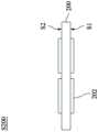
请同时参照图2A和图2B,图2A为依据本发明一些实施例绘示压力传感装置在其中一个制造阶段的俯视图,图2B为依据本发明一些实施例绘示压力传感装置沿图2A中的剖线A-A的截面图。接着,在步骤S200中,提供第二软性基材200,其包括第一表面S1和相对于第一表面S1的第二表面S2。Please refer to FIG. 2A and FIG. 2B at the same time. FIG. 2A is a top view of a pressure sensing device in one of the manufacturing stages according to some embodiments of the present invention, and FIG. 2B is a view of a pressure sensing device along FIG. 2A according to some embodiments of the present invention. Sectional view of section line A-A in. Next, in step S200 , a second
第二软性基材200材料可包括可挠性的聚合物材料,例如PI、TPI、PET、PEN、PU、TPU、其它合适材料、上述的衍生物、或上述材料的任意组合。举例来说,第二软性基材200的材料可包括TPI。在一些实施例中,第二软性基材200的材料可实质上相同于第一软性基材100的材料。The material of the second
在如图2A和图2B所示的实施例中,线路层202形成在第二软性基材200的第一表面S1和第二表面S2上。在一些实施例中,线路层202可能只形成在第一表面S1或第二表面S2上。线路层202的材料可包括金属,例如铝、金、银、铜、锡或其他金属、或上述材料的任意组合。在一些实施例中,线路层202可为铜线路。应注意的是,为了简化附图以清楚说明,线路层202仅绘出一部分线路,例如与电极组500(见图5A)连接的部分。在实际应用上,可根据产品设计或工艺条件来形成完整的线路层202。线路层202可用加成法、半加成法或减成法来制成。In the embodiment shown in FIG. 2A and FIG. 2B , the
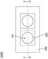
请同时参照图3A和图3B,图3A为依据本发明一些实施例绘示压力传感装置在其中一个制造阶段的俯视图,图3B为依据本发明一些实施例绘示压力传感装置沿图3A中的剖线A-A的截面图。接着,在步骤S300中,形成第一开口O1在第二软性基材200中,其中第一开口O1延伸至第一表面S1和第二表面S2。换言之,第一开口O1可为通孔,贯通第二软性基材200,使第二软性基材200具有连通第一表面S1和第二表面S2的中空结构。Please refer to FIG. 3A and FIG. 3B at the same time. FIG. 3A is a top view of a pressure sensing device in one of the manufacturing stages according to some embodiments of the present invention, and FIG. 3B is a view of a pressure sensing device along FIG. 3A according to some embodiments of the present invention. Sectional view of section line A-A in. Next, in step S300 , a first opening O1 is formed in the second
第一开口O1在俯视图中(例如从第二表面S2观看而成的俯视图中)的形状可为圆形、椭圆形、矩形、菱形、多边形、或任何具对称结构的形状,但本发明不限于此。举例来说,第一开口O1可为线对称图形,其具有至少一条对称轴,若将第一开口O1的图形沿对称轴折叠,则对称轴两侧的部分可以彼此重合。在如图3A所示的实施例中,第一开口O1可为圆形。The shape of the first opening O1 in a plan view (for example, in a plan view viewed from the second surface S2) can be circular, elliptical, rectangular, rhombus, polygonal, or any shape with a symmetrical structure, but the present invention is not limited to this. For example, the first opening O1 can be a line-symmetric figure with at least one axis of symmetry. If the shape of the first opening O1 is folded along the axis of symmetry, the parts on both sides of the axis of symmetry can overlap with each other. In the embodiment shown in FIG. 3A , the first opening O1 may be circular.
第一开口O1的形成方式可包括激光钻孔、机械钻孔、其他合适的技术、或上述材料的任意组合。在一些实施例中,第一开口O1的设置位置可在线路层202的范围内,如图3A所示。在一些实施例中,第一开口O1的尺寸在0.4毫米(mm)至1mm之间。举例来说,在第一开口O1为圆形的实施例中,第一开口O1的直径可在0.4mm至1mm的范围内。The forming method of the first opening O1 may include laser drilling, mechanical drilling, other suitable techniques, or any combination of the above materials. In some embodiments, the location of the first opening O1 may be within the range of the
请同时参照图4A和图4B,图4A为依据本发明一些实施例绘示压力传感装置在其中一个制造阶段的俯视图,图4B为依据本发明一些实施例绘示压力传感装置沿图4A中的剖线A-A的截面图。接着,在步骤S400中,形成导电层400在第一开口O1和第二软性基材200上。详细而言,导电层400形成在第一开口O1的内表面上,以及形成在邻近第一开口O1的第一表面S1和第二表面S2上。Please refer to FIG. 4A and FIG. 4B at the same time. FIG. 4A is a top view of a pressure sensing device in one of the manufacturing stages according to some embodiments of the present invention, and FIG. 4B is a diagram illustrating a pressure sensing device along FIG. 4A according to some embodiments of the present invention Sectional view of section line A-A in. Next, in step S400 , a
在一些实施例中,导电层400可为连续的膜层自第一开口O1的内表面延伸至第一表面S1和第二表面S2上。在一些进一步的实施例中,导电层400完全覆盖第一开口O1的内表面,并沿着第一开口O1的形状而形成在第一表面S1和第二表面S2上。因此,在图4A中的俯视图中(例如从第二表面S2观看而成的俯视图中),导电层400具有连续边缘,并且此连续边缘的形状与第一开口O1的形状基本上是一致的。In some embodiments, the
在一些实施例中,形成导电层400的方式可包括设置图案化遮罩并暴露出待形成导电层400的区域、沉积导电材料,移除图案化遮罩。在另一些实施例中,导电层400的形成方式可包括毯覆式沉积导电材料、以及移除部分导电材料以留下待形成导电层400的区域。沉积方式可包括蒸镀、溅镀、电镀、其他合适的沉积技术、或上述材料的任意组合。举例来说,形成导电层400可包括使用电镀工艺。在使用电镀工艺的实施例中,可借由调整电镀参数(例如电流密度)使导电层400可具有较为平滑的表面以降低电信号传递过程中的噪声,因此可有助于提升装置的可靠度。In some embodiments, the method of forming the
导电层400的材料可包括金属,例如铝、金、银、铜、锡或其他金属、或上述材料的任意组合。在一些实施例中,导电层400的材料可包括铜。The material of the
第二软性基材200可包括裁切区R,在图4A中以断线绘出。裁切区R的范围可涵盖部分的线路层202和部分的导电层400。因此,导电层400可进一步区分出不同部分。举例来说,如图4A所示,导电层400可包括第一部分400-1、第二部分400-2、第三部分400-3和第四部分400-4,其中第一部分400-1和第二部分400-2位在裁切区R的范围之内,而第三部分400-3和第四部分400-4则在裁切区R的范围之外。The second
请同时参照图5A和图5B,图5A为依据本发明一些实施例绘示压力传感装置在其中一个制造阶段的俯视图,图5B为依据本发明一些实施例绘示压力传感装置沿图5A中的剖线A-A的截面图。接着,在步骤S500中,移除裁切区R,意即,移除部分的第二软性基材200、部分的线路层202以及部分的导电层400。在移除之后,形成了第二开口O2在第二软性基材200中。第二开口O2可视为图4A中第一开口O1与裁切区R的集合区域。在一些实施例中,移除裁切区R的方法可包括使用冲压裁切(punch)治具对位裁切区R,然后进行冲压裁切以移除裁切区R。Please refer to FIG. 5A and FIG. 5B at the same time. FIG. 5A is a top view of a pressure sensing device in one of the manufacturing stages according to some embodiments of the present invention, and FIG. 5B is a view of a pressure sensing device along FIG. 5A according to some embodiments of the present invention. Sectional view of section line A-A in. Next, in step S500 , the cutting region R is removed, that is, part of the second
在移除过程中,导电层400的第一部分400-1与相对于第一部分400-1的第二部分400-2被移除,而留下的第三部分400-3和第四部分400-4则分别成为第一电极500-1和第二电极500-2。第一电极50During the removal process, the first portion 400-1 of the
0-1与第二电极500-2彼此相对配置且分开。0-1 and the second electrode 500-2 are disposed opposite to and separated from each other.
详细而言,导电层400的连续边缘(见图4A)在移除过程中被断开而分离出第一电极500-1和第二电极500-2,其中第一电极500-1大致上相同第三部分400-3且第二电极500-2大致上相同第四部分400-4。因为第一电极500-1和第二电极500-2是借由相同的开口(例如第一开口O1)经过冲压裁切而从导电层400(见图4A)分离出来,所以第一电极500-1和第二电极500-2大致上是同时形成。第一电极500-1和第二电极500-2可被合称为电极组500。In detail, the continuous edge of the conductive layer 400 (see FIG. 4A ) is broken during removal to separate the first electrode 500-1 and the second electrode 500-2, wherein the first electrode 500-1 is substantially identical The third part 400-3 and the second electrode 500-2 are substantially the same as the fourth part 400-4. Because the first electrode 500-1 and the second electrode 500-2 are separated from the conductive layer 400 (see FIG. 4A ) by punching and cutting through the same opening (for example, the first opening O1), the first electrode 500- 1 and the second electrode 500-2 are formed substantially simultaneously. The first electrode 500 - 1 and the second electrode 500 - 2 may be collectively referred to as an
电极组500中的第一电极500-1和第二电极500-2的距离可由第一开口O1定义。可借由形成多个第一开口O1而形成多个电极组500。第一开口O1可决定电极组500的配置安排,并且通过调控第一开口O1的尺寸精确度来控制第一电极500-1和第二电极500-2的距离,有助于提升电极组500之间的一致性。A distance between the first electrode 500-1 and the second electrode 500-2 in the
再者,导电层400(见图4A)可视为电极组500的前一阶段,因此,除了导电层400的连续边缘(见图4A)被断开之外,电极组500可具有与导电层400(见图4A)相同的材料,并且电极组500可具有类似导电层400(见图4A)的结构,在此不再详述。举例来说,电极组500设置在第二开口O2中,并且从第二开口O2延伸至第一表面S1和第二表面S2上。详细而言,电极组500中的第一电极500-1覆盖第二开口O2的部分内表面、部分第一表面S1与部分第二表面S2,而电极组500中的第二电极500-2覆盖第二开口O2的部分内表面、部分第一表面S1与部分第二表面S2,其中第一电极500-1与第二电极500-2所覆盖的区域彼此不重叠。Furthermore, the conductive layer 400 (see FIG. 4A ) can be regarded as the previous stage of the
在一些实施例中,在移除导电层404的第一部分400-1与第二部分400-2之后,形成的第一电极500-1和第二电极500-2之间呈现线对称(或称镜射对称),但本发明不限于此。举例来说,如图5A所示,参考对称轴510在第一电极500-1和第二电极500-2之间,若以参考对称轴510为中心进行折叠,则位在参考对称轴510两侧的第一电极500-1和第二电极500-2可以彼此重合。在如图5A所示的实施例中,第一电极500-1具有第一凹面,第二电极500-2具有第二凹面,第一凹面与第二凹面彼此面对面。In some embodiments, after removing the first portion 400-1 and the second portion 400-2 of the conductive layer 404, the formed first electrode 500-1 and the second electrode 500-2 exhibit line symmetry (or called mirror symmetry), but the present invention is not limited thereto. For example, as shown in FIG. 5A, the reference axis of
又或者,第一电极500-1和参考对称轴510之间的距离大致上等于第二电极500-2和参考对称轴510之间的距离。举例来说,第一电极500-1和参考对称轴510相隔第一距离D1,而在相应的位置上,第二电极500-2和参考对称轴510相隔第二距离D2,其中第一距离D1大致上等于第二距离D2。Alternatively, the distance between the first electrode 500 - 1 and the reference axis of
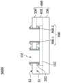
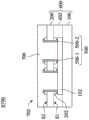
请同时参照图6A和图6B,图6A为依据本发明一些实施例绘示压力传感装置在其中一个制造阶段的俯视图,图6B为依据本发明一些实施例绘示压力传感装置沿图6A中的剖线A-A的截面图。接着,在步骤S600中,压合第一软性基材100与第二软性基材200,使得感压材料102电性连接第一电极500-1与第二电极500-2,其中感压材料102介在第一软性基材100与第二软性基材200之间。Please refer to FIG. 6A and FIG. 6B at the same time. FIG. 6A is a top view of a pressure sensing device in one of the manufacturing stages according to some embodiments of the present invention, and FIG. 6B is a top view of a pressure sensing device according to some embodiments of the present invention along FIG. Sectional view of section line A-A in. Next, in step S600, the first
详细而言,第一软性基材100与第二软性基材200经压合之后,共同形成了第三软性基材600。因此,第三软性基材600可具有第一软性基材100与第二软性基材200。在一些实施例中,可设置胶材602在第一软性基材100与第二软性基材200之间以粘着第一软性基材100与第二软性基材200。因此,第三软性基材600可具有胶材602,但本发明不限于此。In detail, after the first
在如图6B所示的实施例中,第二软性基材200以第一表面S1面向感压材料102,使得位在第一表面S1的电极组500直接接触感压材料102,进而使电极组500电性连接感压材料102。在一些实施例中,第一电极500-1和第二电极500-2皆直接接触感压材料102,使得分隔开的第一电极500-1和第二电极500-2可通过感压材料102而电性连接。In the embodiment shown in FIG. 6B , the second
压合第一软性基材100与第二软性基材200的压合温度在约摄氏180度和约摄氏260度的范围之间。举例来说,在一些进一步的实施例中,可依照所选的材料特性使用约摄氏180度的压合温度。在压合过程中,电极组500的材料可能因接触感压材料102的导电材料而产生融合。为了降低电极组500及感压材料102之间的接触电阻,在一些实施例中,感压材料102的导电材料可具有银,以实现融合后具有较好的电性表现。在一些实施例中,导电材料的银可具有尖端结构(例如导电纳米银线、多支状银等),其中银的尖端结构可优先与电极组500的材料融合以降低接触电阻。感压材料102的导电材料可进一步具有锡或铋,以利与电极组500的材料形成较佳的融合以降低接触电阻。The pressing temperature for laminating the first
除了在感压材料102的导电材料上选用有助于降低接触电阻的材料之外,也可在电极组500的材料上选用有助于降低接触电阻的材料。在一些实施例中,在压合第一软性基材100与第二软性基材200之前,可对电极组500进行表面处理而使电极组500的材料具有锡或银。举例来说,在压合第一软性基材100与第二软性基材200之前,形成银层或锡层(未绘出)在第一电极500-1和第二电极500-2上。在一些实施例中,表面处理的方法可包括对电极组500进行化学镀(无电镀)工艺。当电极组500的材料具有锡或银时,于压合之后,电极组500及感压材料102之间可表现出更低的接触电阻值。In addition to selecting the conductive material of the pressure-
请同时参照图7A和图7B,图7A为依据本发明一些实施例绘示压力传感装置在其中一个制造阶段的俯视图,图7B为依据本发明一些实施例绘示压力传感装置沿图7A中的剖线A-A的截面图。接着,在步骤S700中,形成保护层700在第二软性基材200上,进而制造出压力传感装置702。Please refer to FIG. 7A and FIG. 7B at the same time. FIG. 7A is a top view of a pressure sensing device in one of the manufacturing stages according to some embodiments of the present invention, and FIG. 7B is a view of a pressure sensing device along FIG. 7A according to some embodiments of the present invention. Sectional view of section line A-A in. Next, in step S700 , a
在一些实施例中,保护层700设置在第二软性基材200的第二开口O2(见图6A)中并分布在第一电极500-1与第二电极500-2之间。在一些进一步的实施例中,保护层700填满第二软性基材200的第二开口O2(见图6A),使得第二开口O2的内表面皆直接接触保护层700,意即,保护层700直接接触第一电极500-1与第二电极500-2。保护层700的材料可包括任何合适的绝缘材料,以作为绝缘和保护的作用。在一些实施例中,保护层700的材料可为防焊层。In some embodiments, the
当对压感传感装置702施加压力而产生形变时,相当于第三软性基材600(特别是第二软性基材200)被拉伸,从而感压材料102也跟着拉伸而发生形变。感压材料102受到拉伸后,感压材料102内的导电材料(未绘出)的间距会相应地变大,意即导电材料之间的分布变得稀薄,导致导电材料的导电能力减小,进而感压材料102内部的电信号相应地变化(例如,感压材料102的阻值相应地增大)。因此,通过测量感压材料102的电信号变化可得出外界施加的压力大小的关系(例如,线性关系)。此外,可通过测量多个感压材料102的电信号的总和以得到外界施加的压力大小以提高测量的精度及灵敏度。降低接触电阻可避免电信号与外界施加的压力的关系发生偏差,而提高电极组500的一致性可有助于降低电阻公差。因此,降低接触电阻或提高电极组500的一致性可强化压力感测装置的感测准确度。When pressure is applied to the
综合以上,本发明的实施例提供压力传感装置与其制造方法,借由压合设有感压材料的第一软性基材及设有电极组的第二软性基材,使感压材料与电极组之间在压合之后彼此电性连接并形成良好的接触电阻。除此之外,本发明的电极组由同一孔洞而制成,从而提升电极组中的各个电极的距离长度的一致性,并通过孔洞的精度控制来提升工艺良率,从而降低不同电极组之间的公差。借此,提升压力感测装置的感测准确度。Based on the above, the embodiments of the present invention provide a pressure sensing device and a manufacturing method thereof. By laminating the first flexible substrate provided with the pressure-sensitive material and the second flexible substrate provided with the electrode group, the pressure-sensitive material The electrode group is electrically connected to each other after pressing and forms good contact resistance. In addition, the electrode group of the present invention is made of the same hole, thereby improving the consistency of the distance length of each electrode in the electrode group, and improving the process yield through the precision control of the hole, thereby reducing the difference between different electrode groups. difference between. Thereby, the sensing accuracy of the pressure sensing device is improved.
以上概略说明了本发明数个实施例的特征,使所属技术领域内技术人员对于本发明可更为容易理解。任何所属技术领域内技术人员应了解到本说明书可轻易作为其他结构或工艺的变更或设计基础,以进行相同于本发明实施例的目的及/或获得相同的优点。任何所属技术领域内技术人员也可理解与上述等同的结构并未脱离本发明的精神及保护范围内,且可在不脱离本发明的精神及范围内,可作更动、替代与修改。The features of several embodiments of the present invention are briefly described above, so that those skilled in the art can understand the present invention more easily. Anyone skilled in the art should understand that this description can be easily used as the basis for other structural or process changes or designs to achieve the same purpose and/or obtain the same advantages as the embodiments of the present invention. Anyone skilled in the art can also understand that the structures equivalent to the above do not depart from the spirit and protection scope of the present invention, and can be changed, replaced and modified without departing from the spirit and scope of the present invention.
【符号说明】【Symbol Description】
100:第一软性基材100: the first soft substrate
102:感压材料102: Pressure sensitive material
200:第二软性基材200: the second soft substrate
202:线路层202: line layer
400:导电层400: conductive layer
400-1:第一部分400-1: Part I
400-2:第二部分400-2: Part Two
400-3:第三部分400-3: Part Three
400-4:第四部分400-4: Part Four
500:电极组500: electrode group
500-1:第一电极500-1: first electrode
500-2:第二电极500-2: Second electrode
510:参考对称轴510: Reference symmetry axis
600:第三软性基材600: The third soft substrate
602:胶材602: Glue
700:保护层700: protective layer
702:压力传感装置702: Pressure sensing device
D1:第一距离D1: first distance
D2:第二距离D2: second distance
O1:第一开口O1: first opening
O2:第二开口O2: second opening
R:裁切区R: cutting area
S1:第一表面S1: first surface
S2:第二表面S2: second surface
S100:步骤S100: step
S200:步骤S200: Steps
S300:步骤S300: Steps
S400:步骤S400: Steps
S500:步骤S500: Steps
S600:步骤S600: Steps
S700:步骤S700: Steps
A-A:剖线。A-A: Sectional line.
Claims (17)
Translated fromChinesePriority Applications (2)
| Application Number | Priority Date | Filing Date | Title |
|---|---|---|---|
| CN202111240334.2ACN116026499B (en) | 2021-10-25 | 2021-10-25 | Pressure sensing device and method for manufacturing the same |
| TW110140258ATWI793834B (en) | 2021-10-25 | 2021-10-29 | Pressure sensing device and method of fabricating thereof |
Applications Claiming Priority (1)
| Application Number | Priority Date | Filing Date | Title |
|---|---|---|---|
| CN202111240334.2ACN116026499B (en) | 2021-10-25 | 2021-10-25 | Pressure sensing device and method for manufacturing the same |
Publications (2)
| Publication Number | Publication Date |
|---|---|
| CN116026499Atrue CN116026499A (en) | 2023-04-28 |
| CN116026499B CN116026499B (en) | 2025-06-27 |
Family
ID=86089910
Family Applications (1)
| Application Number | Title | Priority Date | Filing Date |
|---|---|---|---|
| CN202111240334.2AActiveCN116026499B (en) | 2021-10-25 | 2021-10-25 | Pressure sensing device and method for manufacturing the same |
Country Status (2)
| Country | Link |
|---|---|
| CN (1) | CN116026499B (en) |
| TW (1) | TWI793834B (en) |
Citations (11)
| Publication number | Priority date | Publication date | Assignee | Title |
|---|---|---|---|---|
| JPH09145512A (en)* | 1995-11-22 | 1997-06-06 | Omron Corp | Pressure sensor, capacitive sensor, electric device and its manufacture |
| US20030221493A1 (en)* | 2002-06-03 | 2003-12-04 | Sadaharu Morishita | Electrostatic condenser type pressure sensor, and method for manufacturing the pressure sensor |
| JP2008051660A (en)* | 2006-08-24 | 2008-03-06 | Yaskawa Electric Corp | Micro pressure detector |
| US20130118267A1 (en)* | 2011-11-14 | 2013-05-16 | National University Corporation Shizuoka University | Strain Sensor |
| JP2014219318A (en)* | 2013-05-09 | 2014-11-20 | 国立大学法人埼玉大学 | Pressure sensor |
| US20150061047A1 (en)* | 2013-08-28 | 2015-03-05 | Semiconductor Manufacturing International (Shanghai) Corporation | Capacitive pressure sensors and fabrication methods thereof |
| CN105671654A (en)* | 2016-01-21 | 2016-06-15 | 合肥工业大学 | Ionic induction type artificial skin array structure and preparation method thereof |
| US20160327441A1 (en)* | 2014-12-24 | 2016-11-10 | Nippon Mektron, Ltd. | Pressure sensing element and pressure sensor |
| CN107478148A (en)* | 2017-07-13 | 2017-12-15 | 中国科学院深圳先进技术研究院 | A kind of flexible wearable formula electronics strain transducer and preparation method thereof |
| KR20180049677A (en)* | 2016-11-03 | 2018-05-11 | 엘지이노텍 주식회사 | Insol of sensing pressure |
| KR20210076301A (en)* | 2019-12-13 | 2021-06-24 | 한국기계연구원 | Force sensor and method for manufacturing the force sensor |
Family Cites Families (6)
| Publication number | Priority date | Publication date | Assignee | Title |
|---|---|---|---|---|
| JP2015197300A (en)* | 2014-03-31 | 2015-11-09 | パナソニックIpマネジメント株式会社 | PRESSURE-SENSITIVE ELEMENT AND MANUFACTURING METHOD THEREOF, TOUCH PANEL EQUIPPED WITH PRESSURE-SENSITIVE ELEMENT AND ITS MANUFACTURING METHOD |
| CN107003763A (en)* | 2014-11-20 | 2017-08-01 | 东友精细化工有限公司 | Membrane contact sensor and its manufacture method |
| JP6773007B2 (en)* | 2017-11-15 | 2020-10-21 | オムロン株式会社 | Capacitive pressure sensor |
| CN107885390B (en)* | 2017-11-29 | 2021-05-14 | 武汉天马微电子有限公司 | Touch display panel and display device |
| JP2020016437A (en)* | 2018-07-23 | 2020-01-30 | Nissha株式会社 | Pressure sensor and method of manufacturing pressure sensor |
| CN111240528B (en)* | 2020-03-30 | 2024-08-20 | 京东方科技集团股份有限公司 | Touch panel, manufacturing method thereof and display device |
- 2021
- 2021-10-25CNCN202111240334.2Apatent/CN116026499B/enactiveActive
- 2021-10-29TWTW110140258Apatent/TWI793834B/enactive
Patent Citations (11)
| Publication number | Priority date | Publication date | Assignee | Title |
|---|---|---|---|---|
| JPH09145512A (en)* | 1995-11-22 | 1997-06-06 | Omron Corp | Pressure sensor, capacitive sensor, electric device and its manufacture |
| US20030221493A1 (en)* | 2002-06-03 | 2003-12-04 | Sadaharu Morishita | Electrostatic condenser type pressure sensor, and method for manufacturing the pressure sensor |
| JP2008051660A (en)* | 2006-08-24 | 2008-03-06 | Yaskawa Electric Corp | Micro pressure detector |
| US20130118267A1 (en)* | 2011-11-14 | 2013-05-16 | National University Corporation Shizuoka University | Strain Sensor |
| JP2014219318A (en)* | 2013-05-09 | 2014-11-20 | 国立大学法人埼玉大学 | Pressure sensor |
| US20150061047A1 (en)* | 2013-08-28 | 2015-03-05 | Semiconductor Manufacturing International (Shanghai) Corporation | Capacitive pressure sensors and fabrication methods thereof |
| US20160327441A1 (en)* | 2014-12-24 | 2016-11-10 | Nippon Mektron, Ltd. | Pressure sensing element and pressure sensor |
| CN105671654A (en)* | 2016-01-21 | 2016-06-15 | 合肥工业大学 | Ionic induction type artificial skin array structure and preparation method thereof |
| KR20180049677A (en)* | 2016-11-03 | 2018-05-11 | 엘지이노텍 주식회사 | Insol of sensing pressure |
| CN107478148A (en)* | 2017-07-13 | 2017-12-15 | 中国科学院深圳先进技术研究院 | A kind of flexible wearable formula electronics strain transducer and preparation method thereof |
| KR20210076301A (en)* | 2019-12-13 | 2021-06-24 | 한국기계연구원 | Force sensor and method for manufacturing the force sensor |
Also Published As
| Publication number | Publication date |
|---|---|
| TWI793834B (en) | 2023-02-21 |
| CN116026499B (en) | 2025-06-27 |
| TW202318175A (en) | 2023-05-01 |
Similar Documents
| Publication | Publication Date | Title |
|---|---|---|
| JP7429678B2 (en) | Compact pressure and force sensor with integrated leads | |
| US20150296622A1 (en) | Flexible Printed Circuit With Semiconductor Strain Gauge | |
| US20150296607A1 (en) | Electronic Device With Flexible Printed Circuit Strain Gauge Sensor | |
| JP4280774B2 (en) | Small and high-quality mouse pointing device | |
| CN111309175B (en) | Touch panel, preparation method thereof and touch display device | |
| JP2012247372A (en) | Pressure sensor, manufacturing method thereof, and pressure detection module | |
| US10653012B2 (en) | Electronic device and manufacturing method thereof | |
| US10527504B2 (en) | Transparent pressure sensor and manufacturing method thereof | |
| JP2018138887A (en) | Straining body and force sensor including the straining body | |
| JP7189293B2 (en) | battery pack | |
| JP2018138890A (en) | Strain body and force sensor having the strain body | |
| US7040182B2 (en) | Stress sensor | |
| JP6257088B2 (en) | Capacitance type three-dimensional sensor and manufacturing method thereof | |
| TWI793834B (en) | Pressure sensing device and method of fabricating thereof | |
| JP6776151B2 (en) | A strain-causing body and a force sensor equipped with the strain-causing body | |
| CN116547508A (en) | Pressure sensor, pressure-sensitive circuit board and manufacturing method of pressure-sensitive circuit board | |
| US12320718B2 (en) | Pressure sensing circuit board and method for manufacturing the same | |
| CN111078049B (en) | Pressure sensing device, equipment and method for manufacturing pressure sensing device | |
| JP4271447B2 (en) | Stress sensor and manufacturing method thereof | |
| JP2023012248A (en) | MEMS module and its manufacturing method | |
| KR101469149B1 (en) | Touch Panel and Method for Making the Same | |
| TWI803033B (en) | Pressure sensing device and method of fabricating thereof | |
| US20250137857A1 (en) | Sensing module and method of manufacturing the same | |
| WO2020003763A1 (en) | Method for manufacturing pressure-sensitive sensor and pressure-sensitive sensor | |
| TWI484569B (en) | A system in package method |
Legal Events
| Date | Code | Title | Description |
|---|---|---|---|
| PB01 | Publication | ||
| PB01 | Publication | ||
| SE01 | Entry into force of request for substantive examination | ||
| SE01 | Entry into force of request for substantive examination | ||
| GR01 | Patent grant | ||
| GR01 | Patent grant |