CN116006138A - Oil extraction system of plunger gas lift device - Google Patents
Oil extraction system of plunger gas lift deviceDownload PDFInfo
- Publication number
- CN116006138A CN116006138ACN202310083878.5ACN202310083878ACN116006138ACN 116006138 ACN116006138 ACN 116006138ACN 202310083878 ACN202310083878 ACN 202310083878ACN 116006138 ACN116006138 ACN 116006138A
- Authority
- CN
- China
- Prior art keywords
- spiral cover
- cover
- spiral
- sealing plate
- gas lift
- Prior art date
- Legal status (The legal status is an assumption and is not a legal conclusion. Google has not performed a legal analysis and makes no representation as to the accuracy of the status listed.)
- Pending
Links
Images


Landscapes
- Chairs Characterized By Structure (AREA)
Abstract
Description
Translated fromChinese技术领域technical field
本发明涉及石油开采技术领域,尤其涉及一种柱塞气举装置采出油系统。The invention relates to the technical field of oil exploitation, in particular to an oil recovery system of a plunger gas lift device.
背景技术Background technique
油井自喷期间,来源于地层的压力和地层的高压气具有足够的能量可以将原油举升到地面。当油井的地层能量不足以使原油流到地面时,就需要使用气举装置来实现。柱塞气举装置作为气举装置的一种,广泛应用于采油生产中。During oil well blowout, the pressure from the formation and the high-pressure gas in the formation have enough energy to lift crude oil to the ground. When the well's formation energy is insufficient to allow crude oil to flow to the surface, a gas lift device is required to do so. As a kind of gas lift device, plunger gas lift device is widely used in oil production.
现有技术中,套管可以伸入油气井中,柱塞气举装置主要包括:气动阀、控制器以及柱塞本体;气动阀与油管连通,控制器能够控制气动阀打开或关闭。柱塞本体可以在井道内部的上下运动;具体地,当油套环空压力升高到一定值或间隔一定时间后,通过控制器开启气动阀,油管内柱塞以上的气体立刻排出,形成油套环空高压、油管低压的系统,在压差的作用下柱塞本体从油管底部向井口运动,从而将柱塞本体以上液体向上举升并通过气动阀排出;当柱塞本体到达井口后将停留在一端时间,以将井筒内的气、液充分排出;在控制器关闭气动阀后,柱塞本体可以在其重力作用下下落至油管底部,等待下一次举升。In the prior art, the casing can be extended into the oil and gas well, and the plunger gas lift device mainly includes: a pneumatic valve, a controller and a plunger body; the pneumatic valve is connected with the oil pipe, and the controller can control the opening or closing of the pneumatic valve. The plunger body can move up and down inside the well; specifically, when the annular pressure of the oil casing rises to a certain value or after a certain period of time, the pneumatic valve is opened by the controller, and the gas above the plunger in the oil pipe is immediately discharged to form oil Under the action of pressure difference, the plunger body moves from the bottom of the tubing to the wellhead, so that the liquid above the plunger body is lifted upwards and discharged through the pneumatic valve; when the plunger body reaches the wellhead, the Stay at one end for a long time to fully discharge the gas and liquid in the wellbore; after the controller closes the pneumatic valve, the plunger body can fall to the bottom of the tubing under its gravity, waiting for the next lift.
根据上述,目前现有技术中的气举装置存在一个严重缺陷,就是无法实现自身直径的调节控制,无法根据石油井道或油管内壁直径的大小进行适应性调整,因此容易在气举装置和井道之间存在缝隙,导致气液泄漏,从而影响了气举作业。故而鉴于以上缺陷,实有必要设计一种柱塞气举装置采出油系统。According to the above, there is a serious defect in the gas lift device in the prior art, which is that it cannot realize the adjustment and control of its own diameter, and cannot make adaptive adjustments according to the diameter of the inner wall of the oil well or tubing, so it is easy to install between the gas lift device and the well. There are gaps between them, resulting in gas-liquid leakage, which affects the gas lift operation. Therefore, in view of the above defects, it is really necessary to design a plunger gas lift device production oil system.
发明内容Contents of the invention
本发明所要解决的技术问题在于:提供一种柱塞气举装置采出油系统,来解决背景技术提出的问题。The technical problem to be solved by the present invention is to provide a plunger gas lift device recovery oil system to solve the problems raised by the background technology.
为解决上述技术问题,本发明的技术方案是:一种柱塞气举装置采出油系统,包括调控柱芯组件和螺旋柱罩组件,所述调控柱芯组件由加强管、电动推杆、上封板、下封板和调节气阀组成,所述螺旋柱罩组件由第一螺旋罩和第二螺旋罩组成,所述螺旋柱罩组件套设于调控柱芯组件外壁,所述螺旋柱罩组件与调控柱芯组件采用焊接连接,所述电动推杆数量为若干件,所述若干数量的电动推杆从上至下分布于加强管外壁一圈,所述若干数量的电动推杆与加强管采用焊接连接,所述上封板固设于加强管外壁顶端,所述上封板与加强管采用焊接连接,所述下封板固设于加强管外壁底端,所述下封板与加强管采用焊接连接,所述调节气阀固设于加强管内部顶端,所述调节气阀与加强管采用焊接连接,所述第一螺旋罩和第二螺旋罩相互交叉收卷为螺旋状,所述第一螺旋罩和第二螺旋罩位于若干数量的电动推杆外壁,所述第一螺旋罩和第二螺旋罩分别与若干数量的电动推杆采用焊接连接,且所述第一螺旋罩和第二螺旋罩分别与上封板和下封板采用紧密贴合,第一螺旋罩和第二螺旋罩为高回弹性不锈钢,借助自身回弹应力能实现螺旋收卷状态,若干数量的电动推杆相互配合产生的推力值大于第一螺旋罩和第二螺旋罩自身的回弹应力值,若干数量的电动推杆能在推动第一螺旋罩和第二螺旋罩后,实现第一螺旋罩和第二螺旋罩与上封板和下封板在紧密贴合下进行滑动,在不影响第一螺旋罩和第二螺旋罩向外扩大直径的同时,也借助上封板和下封板实现对第一螺旋罩和第二螺旋罩内部空间的封堵,提高密封性,若干数量的电动推杆在收缩复位时,能同步带动第一螺旋罩和第二螺旋罩回缩,且借助第一螺旋罩和第二螺旋罩的回弹应力,使得第一螺旋罩和第二螺旋罩外侧的螺旋部位同步进行收卷,实现直径的缩小,加强管内部顶端的调节气阀能进行开关操作,当打开时,利于外部供气设备将气体通过加强管引导至石油井道底部,增强压力,当井道底部压力大于上方压力时,实现气举作用,利于推动上方石油排出井道,方便了后续的开采作业。In order to solve the above technical problems, the technical solution of the present invention is: a plunger gas lift device production oil system, including a control column core assembly and a spiral column cover assembly, the control column core assembly consists of a reinforcing tube, an electric push rod, The upper sealing plate, the lower sealing plate and the regulating air valve are composed. The spiral column cover assembly is composed of the first spiral cover and the second spiral cover. The spiral column cover assembly is sleeved on the outer wall of the regulating column core assembly. The cover assembly and the control column core assembly are connected by welding. The number of electric push rods is several pieces, and the number of electric push rods is distributed on the outer wall of the reinforced tube from top to bottom. The reinforcing tube is connected by welding, the upper sealing plate is fixed on the top of the outer wall of the reinforcing tube, the upper sealing plate and the reinforcing tube are connected by welding, the lower sealing plate is fixed on the bottom end of the outer wall of the reinforcing tube, and the lower sealing plate It is connected with the reinforced pipe by welding, the regulating air valve is fixed on the inner top of the reinforced pipe, the regulating air valve is connected with the reinforced pipe by welding, and the first spiral cover and the second spiral cover are coiled in a spiral shape , the first spiral cover and the second spiral cover are located on the outer walls of a certain number of electric push rods, the first spiral cover and the second spiral cover are respectively connected to a certain number of electric push rods by welding, and the first spiral cover The cover and the second spiral cover are closely attached to the upper sealing plate and the lower sealing plate respectively. The first screw cover and the second screw cover are made of high-resilience stainless steel, which can realize the spiral winding state by virtue of their own rebound stress. The thrust value generated by the mutual cooperation of the electric push rods is greater than the rebound stress value of the first spiral cover and the second spiral cover itself, and a certain number of electric push rods can realize the first spiral after pushing the first spiral cover and the second spiral cover. The cover and the second screw cover slide with the upper sealing plate and the lower sealing plate in close contact, without affecting the outward expansion of the diameter of the first screw cover and the second screw cover, and also by means of the upper sealing plate and the lower sealing plate Realize the blockage of the inner space of the first screw cover and the second screw cover, and improve the sealing performance. When a certain number of electric push rods are retracted and reset, they can synchronously drive the first screw cover and the second screw cover to retract, and with the help of the second screw cover The rebound stress of the first spiral cover and the second spiral cover makes the spiral parts on the outside of the first spiral cover and the second spiral cover synchronously rewind, realizing the reduction of diameter, and the regulating air valve at the top inside the reinforcing tube can be opened and closed. When it is opened, it is beneficial for the external gas supply equipment to guide the gas to the bottom of the oil well through the reinforced pipe to increase the pressure. When the bottom pressure of the well is greater than the upper pressure, the gas lift effect is realized, which is beneficial to push the upper oil out of the well, and facilitates subsequent mining operations. .
进一步,所述加强管内部还设有流通气腔,所述流通气腔为上下贯通的空心腔体,且所述流通气腔与调节气阀相互连通。Further, the inside of the reinforcing tube is also provided with a flow air cavity, the flow air cavity is a hollow cavity that penetrates up and down, and the flow air cavity communicates with the regulating air valve.
进一步,所述若干数量的电动推杆采用从上至下的交错分布方式,能分别与第一螺旋罩和第二螺旋罩内壁实现点状均匀连接。Further, the number of electric push rods are distributed in a staggered manner from top to bottom, and can be evenly connected to the inner walls of the first spiral cover and the second spiral cover respectively.
进一步,所述第一螺旋罩和第二螺旋罩为310S不锈钢板,厚度为5毫米。Further, the first spiral cover and the second spiral cover are 310S stainless steel plates with a thickness of 5 mm.
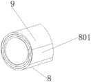
进一步,所述第一螺旋罩和第二螺旋罩的外壁端口为倾斜坡面,能提高在石油井道中平滑的移动,有效降低第一螺旋罩和第二螺旋罩外壁端口在触碰到石油井道内壁石块异物后的翘边问题。Further, the outer wall ports of the first spiral cover and the second spiral cover are inclined slopes, which can improve the smooth movement in the oil well, and effectively reduce the contact between the outer wall ports of the first spiral cover and the second spiral cover when they touch the oil well. The problem of edge warping caused by foreign objects on inner wall stones.
与现有技术相比,该一种柱塞气举装置采出油系统,具备如下优点;Compared with the prior art, the oil recovery system of the plunger gas lift device has the following advantages;
1、首先本发明调控柱芯组件不仅能利于工作人员控制气举状态,此外也亦可对螺旋柱罩组件的直径进行小幅度调控,进而能根据石油井道的直径进行适应性调整,使其更好的匹配石油井道的直径,最大程度紧密贴合在井道内壁,有效预防在气举过程中的气体泄漏问题,增强气举效果。1. First of all, the regulation and control column core assembly of the present invention can not only help the staff to control the gas lift state, but also can adjust the diameter of the spiral column cover assembly in a small range, and then can make adaptive adjustments according to the diameter of the oil well to make it more stable. Well-matched to the diameter of the oil well, it fits closely to the inner wall of the well to the greatest extent, effectively preventing gas leakage during the gas lift process and enhancing the gas lift effect.
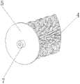
2、其次本发明上封板和下封板夹持在螺旋柱罩组件上下两端,增强对第一螺旋罩和第二螺旋罩的密封,有效避免气流通过第一螺旋罩和第二螺旋罩内部泄漏。2. Secondly, the upper sealing plate and the lower sealing plate of the present invention are clamped at the upper and lower ends of the spiral column cover assembly, which enhances the sealing of the first spiral cover and the second screw cover, and effectively prevents the air flow from passing through the first screw cover and the second screw cover Internal leak.
3、最后本发明因第一螺旋罩和第二螺旋罩均为高回弹性不锈钢,因此借助其回弹应力的收紧力,也能有效避免第一螺旋罩和第二螺旋罩之间连接缝隙的产生,避免空气由第一螺旋罩和第二螺旋罩之间的泄漏问题,进一步增强气举效果。3. Finally, because the first spiral cover and the second spiral cover are both high-resilience stainless steel, the connection gap between the first screw cover and the second screw cover can be effectively avoided by virtue of the tightening force of the rebound stress. The generation of air can avoid the leakage of air from between the first spiral cover and the second spiral cover, and further enhance the gas lift effect.
附图说明Description of drawings
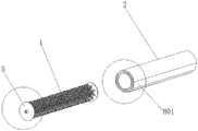
图1是一种柱塞气举装置采出油系统的主视图;Fig. 1 is a front view of a plunger gas lift device production oil system;
图2是一种柱塞气举装置采出油系统的立体图1;Fig. 2 is a perspective view 1 of a production oil system of a plunger gas lift device;
图3是一种柱塞气举装置采出油系统的立体图2;Fig. 3 is a
图4是一种柱塞气举装置采出油系统的分离状态立体图;Fig. 4 is a perspective view of the separation state of the production oil system of a plunger gas lift device;
图5是一种柱塞气举装置采出油系统的A向剖视图;Fig. 5 is an A-direction cross-sectional view of the production oil system of a plunger gas lift device;
图6是加强管位置的立体放大图;Figure 6 is a three-dimensional enlarged view of the position of the reinforcing tube;
图7是上封板部位的放大立体图;Fig. 7 is an enlarged perspective view of the upper sealing plate;
图8是倾斜坡面局部的放大立体图。Fig. 8 is an enlarged perspective view of a part of an inclined slope.
调控柱芯组件1、螺旋柱罩组件2、加强管3、电动推杆4、上封板5、下封板6、调节气阀7、第一螺旋罩8、第二螺旋罩9、流通气腔301、倾斜坡面801。Control column core assembly 1, screw
如下具体实施方式将结合上述附图进一步说明。The following specific embodiments will be further described in conjunction with the above-mentioned drawings.
具体实施方式Detailed ways
在下文中,阐述了多种特定细节,以便提供对构成所描述实施例基础的概念的透彻理解,然而,对本领域的技术人员来说,很显然所描述的实施例可以在没有这些特定细节中的一些或者全部的情况下来实践,在其他情况下,没有具体描述众所周知的处理步骤。In the following text, numerous specific details are set forth in order to provide a thorough understanding of the concepts underlying the described embodiments, however, it will be apparent to those skilled in the art that the described embodiments can be used without these specific details. Some or all instances were practiced, and in other instances well-known process steps were not described in detail.
如图1、图2、图3、图4、图5、图6、图7、图8所示,一种柱塞气举装置采出油系统,包括调控柱芯组件1、螺旋柱罩组件2、加强管3、电动推杆4、上封板5、下封板6、调节气阀7、第一螺旋罩8、第二螺旋罩9、流通气腔301、倾斜坡面801;As shown in Fig. 1, Fig. 2, Fig. 3, Fig. 4, Fig. 5, Fig. 6, Fig. 7, and Fig. 8, a plunger gas lift device production oil system includes a control column core assembly 1 and a screw
在一个实施例中,调控柱芯组件1主要是控制气体流通,利于工作人员控制气举状态,同时亦可对螺旋柱罩组件2的直径进行小幅度调控;In one embodiment, adjusting the column core assembly 1 is mainly to control the gas circulation, which is beneficial for the staff to control the gas lift state, and at the same time, the diameter of the spiral
在一个实施例中,当螺旋柱罩组件2被调节后,进而能根据石油井道的直径进行适应性调整,使其更好的匹配石油井道的直径,最大程度紧密贴合在井道内壁,有效预防在气举过程中的气体泄漏问题,增强气举效果;In one embodiment, when the screw
在一个实施例中,加强管3能增强牢固性,并连接若干数量的电动推杆4和上封板5以及下封板6,同时内部的流通气腔301也利于空气流通,利于气举作业;In one embodiment, the reinforcing
在一个实施例中,上封板5和下封板6夹持在螺旋柱罩组件2上下两端,增强对第一螺旋罩8和第二螺旋罩9的密封,有效避免气流通过第一螺旋罩8和第二螺旋罩9内部泄漏;In one embodiment, the
在一个实施例中,调节气阀7能连接现有技术中的供气设备上的管道,当调节气阀7打开后,能利于外部空气通过调节气阀7进入到流通气腔301中,再由流通气腔301的引导,能利于空气进入到井道深处,达到增强气压目的;In one embodiment, the regulating
在一个实施例中,第一螺旋罩8和第二螺旋罩9均为螺旋状态,并采用相互交叉收卷方式组合为螺旋柱罩组件2,因第一螺旋罩8和第二螺旋罩9内壁分别与若干数量的电动推杆4进行连接,且若干数量的电动推杆相互配合产生的推力值大于第一螺旋罩和第二螺旋罩自身的回弹应力值,因当电动推杆4伸缩时,利于分别带动第一螺旋罩8和第二螺旋罩9进行小幅度的向外扩展,即达到扩大直径目的,同时又因第一螺旋罩8和第二螺旋罩9均为高回弹性不锈钢,因此借助其回弹应力的收紧力,也能有效避免第一螺旋罩8和第二螺旋罩9之间连接缝隙的产生,即达到避免空气由第一螺旋罩8和第二螺旋罩9之间的泄漏问题,进一步增强气举效果;In one embodiment, both the
在一个实施例中,因第一螺旋罩8和第二螺旋罩9为厚度5毫米的310S不锈钢板,进而不仅强度高,此外也实现防腐防锈目的,同时因第一螺旋罩8和第二螺旋罩9的外壁端口为倾斜坡面,因此也能提高在石油井道中平滑的移动,有效降低第一螺旋罩和第二螺旋罩外壁端口在触碰到石油井道内壁石块异物后的翘边问题;In one embodiment, because the
在一个实施例中,因若干数量的电动推杆4采用从上至下的交错分布方式,因此能分别与第一螺旋罩8和第二螺旋罩9内壁实现点状均匀连接,使其能均匀的带动第一螺旋罩8和第二螺旋罩9进行扩大或收缩,同时也增强连接牢固性;In one embodiment, because a certain number of
具体地讲,气举作业操作前,螺旋柱罩组件2的直径小于石油井道内壁直径,以便井道内部的石油能够从井道和螺旋柱罩组件2之间的缝隙处向上渗出,即一部分石油位于该装置的顶部区域,接着工作人员根据井道直径,通过调控若干数量的电动推杆4的伸缩尺寸,达到对螺旋柱罩组件2的直径调节,使其最大程度贴合于石油井道内壁,提高密封性,避免井道底部气液向上泄漏的同时,也能避免该装置顶部的石油向下重新回流到井道底部;气举作业操作时,开启调节气阀7,操作外部供气设备对其进行供气,当井道底部气压大于上方大气压后,借助压差原理,便于该装置顺着井道内壁自下而上运动,即带动上方石油排出,最终实现便捷气举采出油目的。Specifically, before the gas lift operation, the diameter of the spiral
本发明不局限于上述具体的实施方式,本领域的普通技术人员从上述构思出发,不经过创造性的劳动,所做出的种种变换,均落在本发明的保护范围之内。The present invention is not limited to the above-mentioned specific implementation manners, and various transformations made by those skilled in the art starting from the above-mentioned ideas without creative work all fall within the scope of protection of the present invention.
Claims (5)
Translated fromChinesePriority Applications (1)
| Application Number | Priority Date | Filing Date | Title |
|---|---|---|---|
| CN202310083878.5ACN116006138A (en) | 2023-02-09 | 2023-02-09 | Oil extraction system of plunger gas lift device |
Applications Claiming Priority (1)
| Application Number | Priority Date | Filing Date | Title |
|---|---|---|---|
| CN202310083878.5ACN116006138A (en) | 2023-02-09 | 2023-02-09 | Oil extraction system of plunger gas lift device |
Publications (1)
| Publication Number | Publication Date |
|---|---|
| CN116006138Atrue CN116006138A (en) | 2023-04-25 |
Family
ID=86021529
Family Applications (1)
| Application Number | Title | Priority Date | Filing Date |
|---|---|---|---|
| CN202310083878.5APendingCN116006138A (en) | 2023-02-09 | 2023-02-09 | Oil extraction system of plunger gas lift device |
Country Status (1)
| Country | Link |
|---|---|
| CN (1) | CN116006138A (en) |
Citations (8)
| Publication number | Priority date | Publication date | Assignee | Title |
|---|---|---|---|---|
| US20040129428A1 (en)* | 2002-12-20 | 2004-07-08 | Kelley Terry Earl | Plunger lift deliquefying system for increased recovery from oil and gas wells |
| CN200971772Y (en)* | 2006-11-09 | 2007-11-07 | 西南石油大学 | Relay plunger gas-life oil or gas production device |
| CN206111150U (en)* | 2016-10-13 | 2017-04-19 | 中国石油化工股份有限公司 | But reducing water pumping gas production plunger |
| CN209539329U (en)* | 2018-12-20 | 2019-10-25 | 中国石油集团长城钻探工程有限公司 | Intelligent plunger water pumping gas production device |
| CN210422580U (en)* | 2019-09-29 | 2020-04-28 | 霍尔果斯弗莱瑟逆向石油科技有限公司 | Reverse water-control gas production device |
| CN212671714U (en)* | 2020-06-04 | 2021-03-09 | 四川泰和石油科技有限公司 | Wax scraping plunger for plunger gas lifting device |
| CN113236190A (en)* | 2021-06-19 | 2021-08-10 | 西南石油大学 | Diameter-variable plunger of drainage gas production intelligence |
| CN114704228A (en)* | 2022-04-09 | 2022-07-05 | 西南石油大学 | Four-bar linkage supporting mechanism underground drainage gas production robot |
- 2023
- 2023-02-09CNCN202310083878.5Apatent/CN116006138A/enactivePending
Patent Citations (8)
| Publication number | Priority date | Publication date | Assignee | Title |
|---|---|---|---|---|
| US20040129428A1 (en)* | 2002-12-20 | 2004-07-08 | Kelley Terry Earl | Plunger lift deliquefying system for increased recovery from oil and gas wells |
| CN200971772Y (en)* | 2006-11-09 | 2007-11-07 | 西南石油大学 | Relay plunger gas-life oil or gas production device |
| CN206111150U (en)* | 2016-10-13 | 2017-04-19 | 中国石油化工股份有限公司 | But reducing water pumping gas production plunger |
| CN209539329U (en)* | 2018-12-20 | 2019-10-25 | 中国石油集团长城钻探工程有限公司 | Intelligent plunger water pumping gas production device |
| CN210422580U (en)* | 2019-09-29 | 2020-04-28 | 霍尔果斯弗莱瑟逆向石油科技有限公司 | Reverse water-control gas production device |
| CN212671714U (en)* | 2020-06-04 | 2021-03-09 | 四川泰和石油科技有限公司 | Wax scraping plunger for plunger gas lifting device |
| CN113236190A (en)* | 2021-06-19 | 2021-08-10 | 西南石油大学 | Diameter-variable plunger of drainage gas production intelligence |
| CN114704228A (en)* | 2022-04-09 | 2022-07-05 | 西南石油大学 | Four-bar linkage supporting mechanism underground drainage gas production robot |
Similar Documents
| Publication | Publication Date | Title |
|---|---|---|
| CN105967129B (en) | The conceited three-level filling valve inhaled | |
| CN107366510A (en) | A kind of down-hole plugging device and actuating oil-pumping unit with pressure, the workover treatment technology of oil pipe | |
| CN105625276A (en) | A self-closing sluice and method of use thereof | |
| CN110552328A (en) | Stoplog type gate with layered water taking function and working method thereof | |
| CN116006138A (en) | Oil extraction system of plunger gas lift device | |
| CN111472350B (en) | Gas pushing sealing device of immersed tube filling pile machine | |
| CN210317259U (en) | Gas lift device suitable for gas well full life cycle drainage gas production | |
| CN107061252B (en) | Plunger jet pump and oil outlet valve | |
| CN206092991U (en) | Novel boiler continuous blowdown governing valve | |
| CN109812018B (en) | Telescopic pump pipe and use method thereof | |
| CN209995162U (en) | siphon drainage device for culture pond | |
| CN116771982A (en) | Auxiliary bracket for outdoor pipeline laying and construction method | |
| CN205172536U (en) | A gas lift valve for oil well and gas well | |
| CN2902678Y (en) | Blowing mechanism of hollow injection molding equipment | |
| CN108166956B (en) | Nozzle-replaceable throttle and application method thereof | |
| CN117090538A (en) | Injection and production integrated concentric pipe jet pump oil production device of motionless pipe column | |
| CN215595851U (en) | Slide valve type air-lock-proof oil pump | |
| AU2019100015A4 (en) | An Enhanced Gas Lift | |
| CN223399245U (en) | Lifting stop valve | |
| CN207315332U (en) | Injection and production pipe for heavy oil well | |
| CN114352246A (en) | Multi-structure adjustable bridge type concentric water distributor | |
| CN221921998U (en) | High-pressure manual gate valve for oil well | |
| CN221032532U (en) | Hydraulic stage cementing device | |
| CN207188780U (en) | A kind of air pressure insulated pouring device | |
| CN205687531U (en) | The conceited three grades of filling valves inhaled |
Legal Events
| Date | Code | Title | Description |
|---|---|---|---|
| PB01 | Publication | ||
| PB01 | Publication | ||
| SE01 | Entry into force of request for substantive examination | ||
| SE01 | Entry into force of request for substantive examination |