Movatterモバイル変換


[0]ホーム

URL:


CN116000874A - nail gun - Google Patents

nail gun
Download PDF

Info

Publication number
CN116000874A
CN116000874ACN202111148196.5ACN202111148196ACN116000874ACN 116000874 ACN116000874 ACN 116000874ACN 202111148196 ACN202111148196 ACN 202111148196ACN 116000874 ACN116000874 ACN 116000874A
Authority
CN
China
Prior art keywords
tooth
driving
transmission
drive
teeth
Prior art date
Legal status (The legal status is an assumption and is not a legal conclusion. Google has not performed a legal analysis and makes no representation as to the accuracy of the status listed.)
Pending
Application number
CN202111148196.5A
Other languages
Chinese (zh)
Inventor
张俊骝
郝敬东
王小勇
Current Assignee (The listed assignees may be inaccurate. Google has not performed a legal analysis and makes no representation or warranty as to the accuracy of the list.)
Nanjing Chervon Industry Co Ltd
Original Assignee
Nanjing Chervon Industry Co Ltd
Priority date (The priority date is an assumption and is not a legal conclusion. Google has not performed a legal analysis and makes no representation as to the accuracy of the date listed.)
Filing date
Publication date
Application filed by Nanjing Chervon Industry Co LtdfiledCriticalNanjing Chervon Industry Co Ltd
Priority to CN202111148196.5ApriorityCriticalpatent/CN116000874A/en
Priority to CA3229951Aprioritypatent/CA3229951A1/en
Priority to EP22860119.1Aprioritypatent/EP4360809B1/en
Priority to PCT/CN2022/106951prioritypatent/WO2023024773A1/en
Publication of CN116000874ApublicationCriticalpatent/CN116000874A/en
Priority to US18/424,343prioritypatent/US20240246211A1/en
Pendinglegal-statusCriticalCurrent

Links

Images

Landscapes

Abstract

The invention discloses a nail gun, comprising: a housing formed with an accommodating space; a cylinder connected to the housing and for storing a gas; the firing assembly is at least partially arranged in the air cylinder and can move from an initial position to a firing position in the air cylinder to drive out nails; the power output part is arranged in the accommodating space formed by the shell and is used for outputting driving force to drive the firing assembly to move in the cylinder; the driving wheel is connected with the output shaft of the power output part and is used for driving the firing assembly to move in the cylinder under the drive of the power output part; wherein the driving wheel is provided with a first driving tooth and a second driving tooth; the tooth top of the first driving tooth is smaller than the tooth top of the second driving tooth; the first driving teeth are driving teeth arranged at the starting end of the driving wheel and meshed with the firing assembly when the driving wheel starts to drive the firing assembly to reset to the initial position. Provided is a nail gun which can prevent friction of parts caused by the rebound force of a firing pin and has a longer service life.

Description

Translated fromChinese
钉枪nail gun

技术领域technical field

本发明涉及一种钉枪。The invention relates to a nail gun.

背景技术Background technique

市场上现有的钉枪产品的原理方式可分为机械式、气缸式。其中气缸式钉枪通过气缸内的气体推出击发组件执行打钉动作。可以定义击发组件从气缸内的初始位置移动到击发位置,再从击发位置移动到初始位置的过程为一个打钉周期。一般在钉子打出后,击发组件的撞针会由于反弹力的作用而回弹一小段距离,从而会使得撞针的传动齿与驱动轮的驱动齿碰撞。长此以往,将会严重磨损驱动齿或者传动齿,从而影响机器的使用寿命。The principle modes of existing nail gun products on the market can be divided into mechanical type and cylinder type. Wherein the cylinder type nail gun pushes out the firing assembly through the gas in the cylinder to perform the nailing action. The process of the firing assembly moving from the initial position in the cylinder to the firing position, and then from the firing position to the initial position can be defined as a nailing cycle. Generally, after the nail is driven out, the firing pin of the firing assembly will rebound a short distance due to the rebound force, so that the driving gear of the firing pin will collide with the driving gear of the driving wheel. If things go on like this, the driving teeth or transmission teeth will be severely worn, thereby affecting the service life of the machine.

发明内容Contents of the invention

为解决现有技术的不足,本发明的目的在于提供一种整机使用寿命高的钉枪。In order to solve the deficiencies of the prior art, the object of the present invention is to provide a nail gun with a long service life of the whole machine.

为了实现上述目标,本发明采用如下的技术方案:In order to achieve the above object, the present invention adopts the following technical solutions:

一种钉枪,包括:壳体,形成有一个容纳空间;气缸,连接至所述壳体并用于存储气体;击发组件,至少部分设置在所述气缸内,能够在气缸内由初始位置移动到击发位置以打出钉子;动力输出部,设置在所述壳体形成的容纳空间内,用于输出驱动力以驱动所述击发组件在所述气缸内移动;驱动轮,与所述动力输出部的输出轴连接,用以在所述动力输出部的带动下驱动所述击发组件在所述气缸内移动;其中,所述驱动轮具有第一驱动齿和第二驱动齿;所述第一驱动齿的齿顶小于所述第二驱动齿的齿顶;所述第一驱动齿为设置在所述驱动轮起始端的驱动齿,所述第一驱动齿在所述驱动轮开始驱动所述击发组件复位至所述初始位置时与所述击发组件啮合。A nail gun, comprising: a housing formed with an accommodating space; a cylinder connected to the housing and used to store gas; a firing assembly at least partly arranged in the cylinder and capable of moving from an initial position to The firing position is used to drive nails; the power output part is arranged in the accommodation space formed by the casing, and is used to output the driving force to drive the firing assembly to move in the cylinder; the driving wheel is connected with the power output part The output shaft is connected to drive the firing assembly to move in the cylinder under the drive of the power output part; wherein, the driving wheel has a first driving tooth and a second driving tooth; the first driving tooth The tooth top of the second driving tooth is smaller than the tooth top of the second driving tooth; the first driving tooth is a driving tooth arranged at the starting end of the driving wheel, and the first driving tooth starts to drive the firing assembly when the driving wheel starts Engages with the firing assembly when returning to the initial position.

进一步的,所述第二驱动齿为所述所述驱动轮上除所述第一驱动齿之外的驱动齿。Further, the second drive tooth is a drive tooth on the drive wheel other than the first drive tooth.

进一步的,所述第一驱动齿的齿顶与所述第二驱动齿的齿顶的比值为小于1。Further, the ratio of the tooth top of the first driving tooth to the tooth top of the second driving tooth is less than 1.

进一步的,所述第一驱动齿的齿顶与所述第二驱动齿的齿顶的比值为大于或等于0.5且小于1。Further, the ratio of the tooth top of the first driving tooth to the tooth top of the second driving tooth is greater than or equal to 0.5 and less than 1.

进一步的,所述击发组件包括:活塞,位于所述气缸内;撞针,固定在所述活塞上;所述撞针上设有多个传动齿,以与所述驱动轮的驱动齿啮合,在所述驱动轮的驱动下在所述气缸内移动。Further, the firing assembly includes: a piston located in the cylinder; a striker fixed on the piston; a plurality of transmission teeth are provided on the striker to mesh with the drive teeth of the drive wheel, Driven by the drive wheel, it moves in the cylinder.

进一步的,多个传动齿中距离所述活塞的距离由近及远依次包括第一传动齿、第二传动齿以及第三传动齿;所述第二传动齿与所述第三传动齿之间的距离小于所述第一传动齿与所述第二传动齿之间的距离。Further, the distance from the piston among the plurality of transmission teeth includes first transmission teeth, second transmission teeth and third transmission teeth in sequence from near to far; the distance between the second transmission teeth and the third transmission teeth is The distance is smaller than the distance between the first transmission tooth and the second transmission tooth.

进一步的,定义所述驱动轮上除所述第一驱动齿之外的驱动齿与所述撞针除所述第二传动齿之外的传动齿之间具有一定的啮合长度;所述第一驱动齿的齿顶与所述第二驱动齿的齿齿顶具有第一齿顶差值;所述第一齿顶差值与所述啮合长度的比值大于或等于0.2且小于或等于0.7。Further, it is defined that there is a certain meshing length between the driving teeth on the driving wheel except the first driving teeth and the driving teeth of the striker except the second driving teeth; The addendum of the tooth and the addendum of the second driving tooth have a first addendum difference; the ratio of the first addendum difference to the meshing length is greater than or equal to 0.2 and less than or equal to 0.7.

进一步的,所述第二传动齿和所述第三传动齿之间的距离与所述第一传动齿和所述第二传动齿之间的距离的比值小于1。Further, the ratio of the distance between the second transmission tooth and the third transmission tooth to the distance between the first transmission tooth and the second transmission tooth is less than 1.

进一步的,所述第二传动齿的齿高小于所述第一传动齿的齿高或所述第三传动齿的齿高。Further, the tooth height of the second transmission teeth is smaller than the tooth height of the first transmission teeth or the tooth height of the third transmission teeth.

进一步的,所述第一传动齿与所述第二传动齿具有第二齿顶差值;所述第二齿顶差值与所述啮合长度的比值小于1。Further, the first transmission tooth and the second transmission tooth have a second addendum difference; the ratio of the second addendum difference to the meshing length is less than 1.

本发明的有益之处在于:通过合理调整驱动力或者撞针上齿的大小或者距离,可以有效避免撞针打钉后回弹时驱动力与撞针之间的撞击,从而保证钉枪整机使用寿命。The invention is beneficial in that: by reasonably adjusting the driving force or the size or distance of the upper teeth of the firing pin, the impact between the driving force and the firing pin can be effectively avoided when the firing pin rebounds after nailing, thereby ensuring the service life of the nail gun.

附图说明Description of drawings

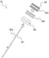
图1是钉枪的立体图;Fig. 1 is the perspective view of nail gun;

图2是图1中的钉枪的剖视图;Fig. 2 is a sectional view of the nail gun in Fig. 1;

图3是图2中的钉枪的动力输出部结构示意图;Fig. 3 is a schematic structural view of the power output part of the nail gun in Fig. 2;

图4是图2中的钉枪的击发组件的爆炸图;Figure 4 is an exploded view of the firing assembly of the nail gun in Figure 2;

图5是图2中的钉枪的击发组件的截面图;Figure 5 is a cross-sectional view of the firing assembly of the nail gun in Figure 2;

图6是图2中的钉枪的驱动轮的立体示意图;Fig. 6 is a three-dimensional schematic view of the driving wheel of the nail gun in Fig. 2;

图7a是图2中的钉枪处于击发位置的内部结构的一种示意图;Fig. 7a is a schematic diagram of the internal structure of the nail gun in Fig. 2 at the fired position;

图7b是图2中的钉枪处于击发位置的内部结构的另一种示意图;Fig. 7b is another schematic diagram of the internal structure of the nail gun in Fig. 2 at the fired position;

图8是图2中的钉枪的撞针的结构示意图。FIG. 8 is a schematic structural view of the striker of the nail gun in FIG. 2 .

具体实施方式Detailed ways

图1至图8所示的钉枪100包括:壳体11,动力输出部12,气缸13、弹夹组件14、电池包15和击发组件16。Thenail gun 100 shown in FIGS. 1 to 8 includes: acasing 11 , apower output portion 12 , acylinder 13 , aclip assembly 14 , abattery pack 15 and afiring assembly 16 .

如图3所示,动力输出部12包括:电机121、变速箱122、止逆组件123、输出轴125和驱动轮125。其中,电机121能输出一个动力至变速箱122,在经过变速箱122的变速后,继续输出一个动力至输出轴125,驱动轮125设置在输出轴125上。具体的,电机121、变速箱122、止逆组件123、输出轴125和驱动轮125均沿第一直线101方向分布。变速箱122中设置有变速机构,止逆组件123设置在变速箱122中,并设置在变速机构的一端或中间。作为一种实现方式,止逆组件123使得输出轴125仅能沿第一转动方向输出一个驱动力,而在与第一转动方向相反的第二转动方向上,限制输出轴125的转动。As shown in FIG. 3 , thepower output unit 12 includes: amotor 121 , agearbox 122 , anon-reverse assembly 123 , anoutput shaft 125 and adriving wheel 125 . Wherein, themotor 121 can output a power to thegearbox 122 , and after being shifted by thegearbox 122 , continue to output a power to theoutput shaft 125 , and thedriving wheel 125 is arranged on theoutput shaft 125 . Specifically, themotor 121 , thegearbox 122 , thenon-reverse assembly 123 , theoutput shaft 125 and thedriving wheel 125 are all distributed along the direction of the firststraight line 101 . Thegearbox 122 is provided with a speed change mechanism, and theanti-reverse assembly 123 is arranged in thegearbox 122 and is arranged at one end or in the middle of the speed change mechanism. As an implementation manner, theanti-reverse assembly 123 enables theoutput shaft 125 to output a driving force only in the first rotation direction, and restricts the rotation of theoutput shaft 125 in the second rotation direction opposite to the first rotation direction.

如图4和图5所示,击发组件16包括撞针161、活塞162和金属件163,其中撞针161固定在金属件163上,活塞162套在金属金163外部。在金属件163上设有金属槽1631,胶圈164套在金属槽1631上。撞针161上形成有传动齿161a,其二者能在气缸13内沿第二直线102方向运动。驱动轮125能与传动齿161a配合从而驱动击发组件16克服气缸13中的气压做功,从而使得击发组件16能进入至击发位置。As shown in FIG. 4 and FIG. 5 , thefiring assembly 16 includes afiring pin 161 , apiston 162 and ametal piece 163 , wherein thefiring pin 161 is fixed on themetal piece 163 , and thepiston 162 is sleeved outside themetal gold 163 . Ametal groove 1631 is provided on themetal piece 163 , and theapron 164 is sleeved on themetal groove 1631 . Atransmission tooth 161 a is formed on thestriker 161 , and both of them can move along the direction of the secondstraight line 102 in thecylinder 13 . Thedriving wheel 125 can cooperate with thetransmission gear 161a to drive thefiring assembly 16 to do work against the air pressure in thecylinder 13, so that thefiring assembly 16 can enter the firing position.

如图1和2所示,壳体11包括沿第一直线101方向延伸形成的第一容纳空间111和沿第二直线102方向延伸形成的第二容纳空间112。其中,动力输出部12设置在第一容纳空间111内,气缸13设置在第二容纳空间112内。壳体11还形成有可供用户握持的把手部113。把手部113一端连接有电源接口,用于接入直流电源或交流电源。把手部113上设置有主开关113a,用户通过主开关113a控制钉枪100的启停。在本实施方式中,电源接口连接有电池包15。把手部113的另一端连接气缸13,气缸13沿第二直线102方向延伸,第一直线101与第二直线102相互垂直。弹夹组件14设置在与第一直线101平行的第三直线103方向上。作为一种可选的实施方式,弹夹组件14还设置有可供用户观察剩余钉子的窗口141。窗口141设置为弹夹组件14上的一个或多个缺口,一方面可供用户查看钉子的余量,另一方面还可供在用户不拆卸弹夹组件14的前提下对弹夹组件14进行简单维修。气缸13中设置有击发组件16,通过气缸13中的气体做功,推动击发组件16运动打出钉子。在本实施方式中,气缸13还包括充气嘴,用于在气缸13中预充气体,动力输出部12驱动驱动轮17转动进而带动击发组件16压缩气体从初始位置运动至击发位置,此时气体做功,并在预充气体的作用下,持续推动击发组件16使之具备一个加速度,从而使得击发组件16以较大的动能打出钉子,并在打出钉子后,迅速从击发位置运动至初始位置,从而完成一个打钉周期。As shown in FIGS. 1 and 2 , thehousing 11 includes a firstaccommodating space 111 extending along a firststraight line 101 and a secondaccommodating space 112 extending along a secondstraight line 102 . Wherein, thepower output part 12 is arranged in thefirst accommodation space 111 , and thecylinder 13 is arranged in thesecond accommodation space 112 . Thecasing 11 is also formed with ahandle portion 113 which can be held by a user. One end of thehandle portion 113 is connected to a power interface for connecting to a DC power supply or an AC power supply. Thehandle portion 113 is provided with amain switch 113a, and the user controls the start and stop of thenail gun 100 through themain switch 113a. In this embodiment, abattery pack 15 is connected to the power interface. The other end of thehandle portion 113 is connected to theair cylinder 13, and theair cylinder 13 extends along the direction of the secondstraight line 102, and the firststraight line 101 and the secondstraight line 102 are perpendicular to each other. Theclip assembly 14 is arranged in the direction of the thirdstraight line 103 parallel to the firststraight line 101 . As an optional implementation, theclip assembly 14 is also provided with awindow 141 for the user to observe the remaining nails. Thewindow 141 is set as one or more gaps on theclip assembly 14, on the one hand, the user can check the remaining amount of nails, and on the other hand, theclip assembly 14 can be checked without the user disassembling theclip assembly 14. Simple maintenance. Afiring assembly 16 is arranged in thecylinder 13, and the gas in thecylinder 13 does work to drive thefiring assembly 16 to drive out a nail. In this embodiment, thecylinder 13 also includes an inflation nozzle for pre-charging the gas in thecylinder 13. Thepower output part 12 drives the driving wheel 17 to rotate and then drives the compressed gas of thefiring assembly 16 to move from the initial position to the firing position. At this time, the gas Do work, and under the action of the pre-inflated gas, continue to push thefiring assembly 16 to have an acceleration, so that thefiring assembly 16 drives the nail with a large kinetic energy, and after the nail is driven, it quickly moves from the firing position to the initial position, Thereby complete a nailing cycle.

可以理解的,在击发组件16打出钉子时,由于打击物的反弹力可使击发组件16从打击位置向上回弹一小段距离。在击发组件16回弹的过程中会造成撞针161与驱动轮125之间的撞击,从而磨损驱动轮125的驱动齿和/或撞针161上的传动齿。为了解决上述问题,本申请对驱动轮125和或撞针161的结构进行了优化设计,从而避免撞针161回弹时,对驱动轮125撞击造成驱动齿和传动齿的磨损。It can be understood that when thefiring assembly 16 drives a nail, thefiring assembly 16 can bounce back a short distance upwards from the striking position due to the rebound force of the striking object. During the rebounding process of thefiring assembly 16 , impact between thefiring pin 161 and thedriving wheel 125 will be caused, thereby wearing the driving teeth of thedriving wheel 125 and/or the transmission teeth on thefiring pin 161 . In order to solve the above problems, the present application optimizes the structure of thedriving wheel 125 and/or thestriker 161 , so as to avoid the wear of the driving teeth and transmission teeth caused by the strike of thedriving wheel 125 when thestriker 161 rebounds.

具体实现中,如图6所示,驱动轮125为一个齿轮结构。驱动轮125还形成有可供输出轴125连接的连接孔125a。连接孔125a具体为一个扁位孔,当输出轴125连接至连接孔125a时,驱动轮125能随输出轴125同步转动。围绕驱动轮125的主体部形成有多个驱动齿125g,驱动齿125g包括设置在起始端的第一驱动齿125b和除了第一驱动齿125b之外的其他驱动齿125g。本申请中,将驱动齿125上出第一驱动齿125b之外的驱动齿统称为第二驱动齿。这里,驱动轮125开始驱动击发组件16复位至初始位置时与击发组件16中的撞针161最先开始接触的驱动齿125g即为第一驱动齿125b,除了第一驱动齿125b之外的其他驱动齿均为第二驱动齿125d。第一驱动齿125b和第二驱动齿125d均匀分布在驱动轮125的第一区段125e;驱动轮125的第二区段125f光滑且连续,且不分布有驱动齿125g。如图7a和图7b所示,当第一区段125e的驱动齿125g与撞针161上的传动齿161a啮合时,驱动轮125能驱动撞针161压缩气缸13中的气体做功。更具的的是第一区段125e上的第一驱动齿125b开始与撞针161上的传动齿161a啮合时,驱动轮125开始驱动撞针161推动活塞压缩气缸13中的气体做功。当第二区段125f与撞针161配合时,由于第二区段125f光滑且连续,撞针161在没有驱动齿125g止挡的情况下,会被气缸13中的气体迅速推出,从而实现打钉效果。In a specific implementation, as shown in FIG. 6 , thedriving wheel 125 is a gear structure. Thedriving wheel 125 is also formed with a connectinghole 125 a for connecting theoutput shaft 125 . The connectinghole 125a is specifically a flat hole. When theoutput shaft 125 is connected to the connectinghole 125a, thedriving wheel 125 can rotate synchronously with theoutput shaft 125 . A plurality of drivingteeth 125g are formed around the main body of thedriving wheel 125, and the drivingteeth 125g include afirst driving tooth 125b disposed at a starting end and other drivingteeth 125g except thefirst driving tooth 125b. In this application, the driving teeth on the drivingteeth 125 other than the first drivingteeth 125 b are collectively referred to as the second driving teeth. Here, when thedriving wheel 125 starts to drive the firingassembly 16 to return to the initial position, the drivingtooth 125g that first comes into contact with thefiring pin 161 in the firingassembly 16 is thefirst driving tooth 125b. Other driving teeth except thefirst driving tooth 125b The teeth are all thesecond driving teeth 125d. Thefirst driving teeth 125b and thesecond driving teeth 125d are evenly distributed in thefirst section 125e of thedriving wheel 125; thesecond section 125f of thedriving wheel 125 is smooth and continuous, and no drivingteeth 125g are distributed therein. As shown in FIG. 7 a and FIG. 7 b , when thedriving gear 125 g of thefirst section 125 e meshes with thedriving gear 161 a on thestriker 161 , thedrive wheel 125 can drive thestriker 161 to compress the gas in thecylinder 13 to do work. What's more, when thefirst driving tooth 125b on thefirst section 125e starts to mesh with thetransmission tooth 161a on thestriker 161, thedrive wheel 125 starts to drive thestriker 161 to push the piston to compress the gas in thecylinder 13 to do work. When thesecond section 125f cooperates with thestriker 161, since thesecond section 125f is smooth and continuous, thestriker 161 will be quickly pushed out by the gas in thecylinder 13 without the stop of the drivingtooth 125g, thereby realizing the nailing effect .

可以理解的,撞针161的一侧分布由传动齿161a,传动齿161a能与驱动轮125的驱动齿125g啮合,从而在驱动轮125的驱动下撞针161能带动活塞在气缸内压缩气体做功。It can be understood that one side of thestriker 161 is distributed withtransmission teeth 161a, and thetransmission teeth 161a can mesh with thedrive teeth 125g of thedrive wheel 125, so that thestriker 161 can drive the piston to perform work by compressing gas in the cylinder under the drive of thedrive wheel 125.

在一个实施例中,如图6所示,驱动轮125的第一驱动齿125b的齿顶H1小于第二驱动齿125d的齿顶H2。其中,H1和H2为图6中加粗实线所表示的高度。另外,由图6中第一驱动齿125b所在的第一齿圈C1和第二齿圈C2的直径也可以明显看出,第一驱动齿125b的齿顶明显小于第二驱动会125d的齿顶。在一种优选的实现方式中,第一驱动齿125b的齿顶H1与第二驱动齿125d的齿顶H2的比值为小于1。优选的,H1与H2的比值大于或等于0.5且小于1。通过降低第一驱动齿125b齿顶H1的高度,在撞针161由于反弹力向上移动时,将大大降低传动齿161a对第一驱动齿125b的撞击力度,从而降低二者之间的磨损程度,避免由于撞针161和驱动轮125的摩擦而影响整机寿命。In one embodiment, as shown in FIG. 6 , the tooth top H1 of thefirst driving tooth 125 b of thedriving wheel 125 is smaller than the tooth top H2 of thesecond driving tooth 125 d. Wherein, H1 and H2 are heights indicated by bold solid lines in FIG. 6 . In addition, it can be clearly seen from the diameters of the first ring gear C1 and the second ring gear C2 where thefirst drive tooth 125b is located in FIG. . In a preferred implementation manner, the ratio of the tooth top H1 of thefirst driving tooth 125b to the tooth top H2 of thesecond driving tooth 125d is less than 1. Preferably, the ratio of H1 to H2 is greater than or equal to 0.5 and less than 1. By reducing the height of the tooth top H1 of thefirst driving tooth 125b, when thestriker 161 moves upward due to the rebound force, the impact force of the drivingtooth 161a on thefirst driving tooth 125b will be greatly reduced, thereby reducing the degree of wear between the two and avoiding Due to the friction between thestriker 161 and thedriving wheel 125, the life of the whole machine is affected.

由图7a所示,在撞针161由于反弹力向上移动时,第一驱动齿125b与传动齿161a不能啮合或者两个齿啮合的长度较小。进一步的,由图7b所示,第二驱动齿125d与传动齿161a啮合时啮合长度较大。As shown in FIG. 7a, when thestriker 161 moves upward due to the rebound force, thefirst driving tooth 125b cannot mesh with thetransmission tooth 161a or the length of the two teeth meshing is relatively small. Further, as shown in FIG. 7 b , when thesecond driving tooth 125 d meshes with thetransmission tooth 161 a, the meshing length is relatively large.

在一个实施例中,第一驱动齿125b的齿顶与第二驱动齿125d的齿顶具有一定的第一齿顶差值;驱动轮125上除第一驱动齿125b之外的驱动齿与撞针161上除第二传动齿1613之外的传动齿之间具有一定的啮合长度。在一个实施例中,上述第一齿顶差值与上述啮合长度的比值大于或等于0.2且小于或等于0.7。事例性的,上述第一齿顶差值与上述啮合长度的比值为0.2、0.3、0.4、0.5、0.6、0.7。在一个实施例中,如图8所示,依据传动齿161a距离活塞162的距离,将撞针161的传动齿161a依次定义为第一传动齿1612、第二传动齿1613以及第三传动齿1614等。可以理解的,在撞针161由击发位置移动至初始位置的过程中,第一传动齿1612最先与驱动轮125的第一驱动齿125b啮合。也就是说,若撞针161打钉后由于反弹力向上移动时,第二传动齿1613最先与第一驱动齿125b撞击。在一种实现方式中,可以增加第一传动齿1612与第二传动齿1613之间的距离。事例性的,假设撞针161的第一传动齿1612与第二传动齿1613之间的距离为S1,第二传动齿1613与第三传动齿1614之间的距离为S2,则S1大于S2。可选的,除了第一传动齿1612与第二传动齿1613之外,其他另个相邻的传动齿161a之间的距离均为S2。通过增加第一传动齿1612与第二传动齿1613之间的距离,在撞针161打钉后反弹的过程中,反弹的力在撞针161移动S1距离的过程中转换为带动撞针161移动的驱动力而被消耗掉,从而避免或者降低了驱动轮125与撞针161之间的撞击力度。在一种优选的实现方式中,S1与S2的比值小于1。优选的,S1与S2的比值大于或等于0.5且小于1。在一个实施例中,可以根据气缸13内压力的大小增加第一传动齿1612与第二传动齿1613之间的距离。事例性的,气缸13内压力越大所设置的第一传动齿1612与第二传动齿1613之间的距离S1越大。可以理解的,S1除了与气缸13内的压强相关,还与撞针161的传动齿的齿厚度或者齿轮的模数相关。In one embodiment, the tooth top of thefirst driving tooth 125b and the tooth top of thesecond driving tooth 125d have a certain first tooth top difference; There is a certain meshing length between the transmission teeth on 161 except thesecond transmission teeth 1613 . In one embodiment, the ratio of the first addendum difference to the meshing length is greater than or equal to 0.2 and less than or equal to 0.7. Exemplarily, the ratios of the first addendum difference to the meshing length are 0.2, 0.3, 0.4, 0.5, 0.6, 0.7. In one embodiment, as shown in FIG. 8 , according to the distance between thetransmission teeth 161a and thepiston 162, thetransmission teeth 161a of thestriker 161 are sequentially defined as thefirst transmission teeth 1612, thesecond transmission teeth 1613, and thethird transmission teeth 1614, etc. . It can be understood that, when thestriker 161 moves from the firing position to the initial position, thefirst transmission gear 1612 meshes with thefirst driving gear 125 b of thedriving wheel 125 first. That is to say, if thestriker 161 moves upward due to the rebound force after nailing, thesecond driving tooth 1613 collides with thefirst driving tooth 125b first. In one implementation manner, the distance between thefirst transmission tooth 1612 and thesecond transmission tooth 1613 can be increased. For example, assuming that the distance between thefirst transmission tooth 1612 and thesecond transmission tooth 1613 of thestriker 161 is S1, and the distance between thesecond transmission tooth 1613 and thethird transmission tooth 1614 is S2, then S1 is greater than S2. Optionally, except for thefirst transmission tooth 1612 and thesecond transmission tooth 1613, the distance between otheradjacent transmission teeth 161a is S2. By increasing the distance between thefirst transmission tooth 1612 and thesecond transmission tooth 1613, during the rebound process of thestriker 161 after nailing, the rebound force is converted into the driving force driving thestriker 161 to move when thestriker 161 moves the distance S1 and be consumed, thereby avoiding or reducing the impact force between thedriving wheel 125 and thestriker 161 . In a preferred implementation manner, the ratio of S1 to S2 is less than 1. Preferably, the ratio of S1 to S2 is greater than or equal to 0.5 and less than 1. In one embodiment, the distance between thefirst transmission tooth 1612 and thesecond transmission tooth 1613 can be increased according to the pressure in thecylinder 13 . For example, the greater the pressure in thecylinder 13 is, the greater the distance S1 between thefirst transmission tooth 1612 and thesecond transmission tooth 1613 is set. It can be understood that, in addition to being related to the pressure in thecylinder 13 , S1 is also related to the tooth thickness of the transmission teeth of thestriker 161 or the modulus of the gear.

在一个实施例中,可以降低撞针161的第二传动齿1613的齿高H3,即第二传动齿1613的齿高小于第一传动齿1612的齿高或第三传动齿1614的齿高。可选的,第二传动齿1613的齿高为所有传动齿161a中齿高最小的传动齿。在撞针161打钉后反弹的过程中,反弹力驱动撞针161上移,由于第二传动齿1613较小,撞针161上移过程中第一驱动齿125b可能与之发生碰撞或者与之不接触。若撞针161上移过程中第一驱动齿125b与第二传动齿1613不接触,反弹力驱动撞针移动距离S3后,第一驱动齿125b与第三传动齿1614之间的撞击力度也将大大降低。其中,距离S3为第一传动齿1612与第三传动齿1614之间的距离即S3=S1+S2。若撞针161上移过程中第一驱动齿125b与齿高较低的第二动齿1613发生第一次撞击,则该撞击力度也不会对驱动轮125造成较大的磨损,范围会较大的低效掉反弹力,避免第一驱动齿125b与第三传动齿1614之间造成较大的第二次撞击力度,影响驱动轮125和撞针161的使用寿命。In one embodiment, the tooth height H3 of thesecond transmission tooth 1613 of thestriker 161 can be reduced, that is, the tooth height of thesecond transmission tooth 1613 is smaller than the tooth height of thefirst transmission tooth 1612 or the tooth height of thethird transmission tooth 1614 . Optionally, the tooth height of thesecond transmission tooth 1613 is the transmission tooth with the smallest tooth height among all thetransmission teeth 161a. During the rebound process of thestriker 161 after nailing, the rebound force drives thestriker 161 to move upward. Since thesecond drive tooth 1613 is small, thefirst drive tooth 125b may collide with it or not contact it during the upward movement of thestriker 161 . If thefirst driving tooth 125b and thesecond driving tooth 1613 do not contact during the upward movement of thestriker 161, the impact force between thefirst driving tooth 125b and thethird transmission tooth 1614 will also be greatly reduced after the rebound force drives the striker to move the distance S3 . Wherein, the distance S3 is the distance between thefirst transmission tooth 1612 and thethird transmission tooth 1614 ie S3=S1+S2. If thefirst driving tooth 125b collides with the secondmovable tooth 1613 with a lower tooth height during the upward movement of thestriker 161, the force of the collision will not cause greater wear to thedriving wheel 125, and the range will be larger. The low-efficiency drop of the rebound force avoids a large second impact force between thefirst driving tooth 125b and thethird driving tooth 1614, which affects the service life of thedriving wheel 125 and thestriker 161.

也就是说,通过降低第二传动齿1613的高度,变相的增加了反弹力所能驱动撞针161移动的距离,该距离即为第一传动齿1612与第三传动齿1614之间的距离。从而避免或者降低传动轮125的第一驱动齿125b与撞针161的第一传动齿1612之间的撞击力度。That is to say, by reducing the height of thesecond transmission tooth 1613 , the distance that the rebound force can drive thestriker 161 to move is increased in a disguised form, and the distance is the distance between thefirst transmission tooth 1612 and thethird transmission tooth 1614 . In this way, the collision force between thefirst driving tooth 125 b of thetransmission wheel 125 and thefirst transmission tooth 1612 of thestriker 161 is avoided or reduced.

在一种可选的实现方式中,第二传动齿1613的齿顶高度H3与第一驱动齿125b的齿顶高度H1的比值小于1。可以理解的,第二传动齿1613的齿顶高度H4可以根据第一驱动齿125b的齿顶高度H1设置,只需保证撞针161能在第二传动齿1613与第一驱动齿125b之间的撞击力较小。也就是说,在撞针161向上回弹时,第二传动齿1613也可以与第一驱动齿125b之间具有一定的撞击力度,只要该撞击力度足够小,以至其不会对传动齿和/或驱动齿之间造成较大的磨损即可。In an optional implementation manner, the ratio of the addendum height H3 of thesecond transmission tooth 1613 to the addendum height H1 of thefirst driving tooth 125b is less than 1. It can be understood that the addendum height H4 of thesecond drive tooth 1613 can be set according to the addendum height H1 of thefirst drive tooth 125b, only need to ensure that thestriker 161 can strike between thesecond drive tooth 1613 and thefirst drive tooth 125b less force. That is to say, when thestriker 161 rebounds upwards, there may also be a certain impact force between thesecond transmission tooth 1613 and thefirst drive tooth 125b, as long as the impact force is small enough so that it will not impact the transmission tooth and/or It is sufficient to cause greater wear between the drive teeth.

在一个实施例中,第一传动齿1612与第二传动齿1613或者第四传动齿1514之间具有第二齿顶差值,该齿顶差值与上述啮合长度的比值小于1。事例性的,第二齿顶差值与上述啮合长度的比值为0.2、0.3、0.4、0.5、0.6、0.7等。In one embodiment, there is a second addendum difference between thefirst transmission tooth 1612 and thesecond transmission tooth 1613 or the fourth transmission tooth 1514 , and the ratio of the addendum difference to the aforementioned meshing length is less than 1. Exemplarily, the ratio of the second addendum difference to the aforementioned meshing length is 0.2, 0.3, 0.4, 0.5, 0.6, 0.7 and so on.

在一个实施例中,也可以通过电机的控制器控制电机转速改变。事例性的,在驱动轮125驱动撞针161由初始位置移动到击发位置的过程中,控制器控制电机降低转速,或者在驱动轮126驱动撞针161由初始位置移动到击发位置,并开始从击发位置上升至初始位置时,降低电机转速。总之,可以在撞针161即将向上移动或者已将向上移动的过程中降低电机转速,从而可以降低撞针161上下反弹的力度。In an embodiment, the change of the motor speed can also be controlled by the controller of the motor. Illustratively, during the process of driving thefiring pin 161 from the initial position to the firing position by thedriving wheel 125, the controller controls the motor to reduce the rotation speed, or the driving wheel 126 drives thefiring pin 161 to move from the initial position to the firing position, and starts to move from the firing position to the firing position. When rising to the initial position, reduce the motor speed. In a word, the rotation speed of the motor can be reduced when thestriker 161 is about to move up or has already moved up, so that the strength of thestriker 161 bouncing up and down can be reduced.

在一个实施例中,可以采用一种或多多种方式的组合来降低驱动轮125和撞针161撞击力度。In one embodiment, one or more combinations of methods can be used to reduce the impact force of thedriving wheel 125 and thestriker 161 .

可以理解的是,击发组件16重量越大,气缸13内气体压缩后气体的做功将越多的用于克服击发组件16本身的惯性做功,从而打击力度将大大降低。也就是说,击发组件16即活塞162和撞针161的重量越大钉枪的打钉效果越差。It can be understood that the greater the weight of thepercussion assembly 16, the more work the compressed gas in thecylinder 13 will do to overcome the inertia of thepercussion assembly 16 itself, thereby greatly reducing the striking force. That is to say, the greater the weight of the firingassembly 16, that is, thepiston 162 and thestriker 161, the worse the nailing effect of the nail gun.

因此可以通过降低击发组件16本申请的重量来提升钉枪的打钉效果。可选的,可以通过选用材质较轻但质地较硬的材料制作撞针161,或者选用材质更轻防撞性能更好的材质制作活塞。Therefore, the nailing effect of the nail gun can be improved by reducing the weight of the firingassembly 16 of the present application. Optionally, thestriker 161 can be made of a lighter material but harder, or the piston can be made of a lighter material with better anti-collision performance.

事例性的,可以将如图4和图5所示的金属件163中间部分挖空,以减少金属金163的重量,从而降低击发组件16的重量。As an example, the middle part of themetal piece 163 as shown in FIG. 4 and FIG. 5 can be hollowed out to reduce the weight of themetal gold 163 , thereby reducing the weight of the firingassembly 16 .

以上显示和描述了本发明的基本原理、主要特征和优点。本行业的技术人员应该了解,上述实施例不以任何形式限制本发明,凡采用等同替换或等效变换的方式所获得的技术方案,均落在本发明的保护范围内。The basic principles, main features and advantages of the present invention have been shown and described above. Those skilled in the industry should understand that the above-mentioned embodiments do not limit the present invention in any form, and all technical solutions obtained by means of equivalent replacement or equivalent transformation fall within the protection scope of the present invention.

Claims (10)

Translated fromChinese
1.一种钉枪,包括:1. A nail gun, comprising:壳体,形成有一个容纳空间;The housing is formed with a receiving space;气缸,连接至所述壳体并用于存储气体;a gas cylinder connected to the housing and used to store gas;击发组件,至少部分设置在所述气缸内,能够在气缸内由初始位置移动到击发位置以打出钉子;a firing assembly, at least partially disposed within the cylinder, capable of moving within the cylinder from an initial position to a firing position for driving nails;动力输出部,设置在所述壳体形成的容纳空间内,用于输出驱动力以驱动所述击发组件在所述气缸内移动;a power output part, arranged in the accommodation space formed by the casing, for outputting driving force to drive the firing assembly to move in the cylinder;驱动轮,与所述动力输出部的输出轴连接,用以在所述动力输出部的带动下驱动所述击发组件在所述气缸内移动;A driving wheel, connected to the output shaft of the power output part, used to drive the firing assembly to move in the cylinder driven by the power output part;其特征在于,It is characterized in that,所述驱动轮具有第一驱动齿和第二驱动齿;The drive wheel has a first drive tooth and a second drive tooth;所述第一驱动齿的齿顶小于所述第二驱动齿的齿顶;The addendum of the first drive tooth is smaller than the addendum of the second drive tooth;所述第一驱动齿为设置在所述驱动轮起始端的驱动齿,所述第一驱动齿在所述驱动轮开始驱动所述击发组件复位至所述初始位置时与所述击发组件啮合。The first driving tooth is a driving tooth arranged at the starting end of the driving wheel, and the first driving tooth meshes with the firing assembly when the driving wheel starts to drive the firing assembly back to the initial position.2.根据权利要求1所述的钉枪,其特征在于,2. The nail gun according to claim 1, wherein:所述第二驱动齿为所述所述驱动轮上除所述第一驱动齿之外的驱动齿。The second driving tooth is a driving tooth on the driving wheel except the first driving tooth.3.根据权利要求1所述的钉枪,其特征在于,3. The nail gun according to claim 1, wherein:所述第一驱动齿的齿顶与所述第二驱动齿的齿顶的比值为小于1。The ratio of the tooth top of the first driving tooth to the tooth top of the second driving tooth is less than 1.4.根据权利要求1所述的钉枪,其特征在于,4. The nail gun according to claim 1, wherein:所述第一驱动齿的齿顶与所述第二驱动齿的齿顶的比值为大于或等于0.5且小于1。A ratio of a tooth top of the first driving tooth to a tooth top of the second driving tooth is greater than or equal to 0.5 and less than 1.5.根据权利要求1所述的钉枪,其特征在于,5. The nail gun according to claim 1, wherein:所述击发组件包括:The firing components include:活塞,位于所述气缸内;a piston located within said cylinder;撞针,固定在所述活塞上;a striker fixed to said piston;所述撞针上设有多个传动齿,以与所述驱动轮的驱动齿啮合,在所述驱动轮的驱动下在所述气缸内移动。The striker is provided with a plurality of transmission teeth to mesh with the drive teeth of the drive wheel, and is driven by the drive wheel to move in the cylinder.6.根据权利要求5所述的钉枪,其特征在于,6. The nail gun according to claim 5, wherein:多个传动齿中距离所述活塞的距离由近及远依次包括第一传动齿、第二传动齿以及第三传动齿;The distance from the piston among the plurality of transmission teeth includes the first transmission tooth, the second transmission tooth and the third transmission tooth in order from near to far;所述第二传动齿与所述第三传动齿之间的距离小于所述第一传动齿与所述第二传动齿之间的距离。The distance between the second transmission tooth and the third transmission tooth is smaller than the distance between the first transmission tooth and the second transmission tooth.7.根据权利要求6所述的钉枪,其特征在于,7. The nail gun according to claim 6, wherein:定义所述驱动轮上除所述第一驱动齿之外的驱动齿与所述撞针除所述第二传动齿之外的传动齿之间具有一定的啮合长度;Define that there is a certain meshing length between the driving teeth on the driving wheel except the first driving teeth and the driving teeth of the striker except the second driving teeth;所述第一驱动齿的齿顶与所述第二驱动齿的齿齿顶具有第一齿顶差值;The addendum of the first drive tooth and the addendum of the second drive tooth have a first addendum difference;所述第一齿顶差值与所述啮合长度的比值大于或等于0.2且小于或等于0.7。A ratio of the first addendum difference to the meshing length is greater than or equal to 0.2 and less than or equal to 0.7.8.根据权利要求6所述的钉枪,其特征在于,8. The nail gun according to claim 6, wherein:所述第二传动齿和所述第三传动齿之间的距离与所述第一传动齿和所述第二传动齿之间的距离的比值小于1。A ratio of the distance between the second transmission tooth and the third transmission tooth to the distance between the first transmission tooth and the second transmission tooth is less than 1.9.根据权利要求6所述的钉枪,其特征在于,9. The nail gun according to claim 6, wherein:所述第二传动齿的齿高小于所述第一传动齿的齿高或所述第三传动齿的齿高。The tooth height of the second transmission teeth is smaller than the tooth height of the first transmission teeth or the tooth height of the third transmission teeth.10.根据权利要求7所述的钉枪,其特征在于,10. The nail gun according to claim 7, wherein:所述第一传动齿与所述第二传动齿具有第二齿顶差值;The first transmission tooth and the second transmission tooth have a second addendum difference;所述第二齿顶差值与所述啮合长度的比值小于1。A ratio of the second addendum difference to the meshing length is less than 1.
CN202111148196.5A2021-08-252021-09-29 nail gunPendingCN116000874A (en)

Priority Applications (5)

Application NumberPriority DateFiling DateTitle
CN202111148196.5ACN116000874A (en)2021-09-292021-09-29 nail gun
CA3229951ACA3229951A1 (en)2021-08-252022-07-21Nail gun
EP22860119.1AEP4360809B1 (en)2021-08-252022-07-21Nail gun
PCT/CN2022/106951WO2023024773A1 (en)2021-08-252022-07-21Nail gun
US18/424,343US20240246211A1 (en)2021-08-252024-01-26Nail gun

Applications Claiming Priority (1)

Application NumberPriority DateFiling DateTitle
CN202111148196.5ACN116000874A (en)2021-09-292021-09-29 nail gun

Publications (1)

Publication NumberPublication Date
CN116000874Atrue CN116000874A (en)2023-04-25

Family

ID=86034065

Family Applications (1)

Application NumberTitlePriority DateFiling Date
CN202111148196.5APendingCN116000874A (en)2021-08-252021-09-29 nail gun

Country Status (1)

CountryLink
CN (1)CN116000874A (en)

Cited By (1)

* Cited by examiner, † Cited by third party
Publication numberPriority datePublication dateAssigneeTitle
CN116901004A (en)*2023-08-172023-10-20浙江普莱得电器股份有限公司Efficient trochoid roller rack structure and nail gun

Citations (5)

* Cited by examiner, † Cited by third party
Publication numberPriority datePublication dateAssigneeTitle
US20060180631A1 (en)*2005-02-162006-08-17Chris PediciniElectric motor driven energy storage device for impacting
US20190126452A1 (en)*2017-11-022019-05-02Basso Industry Corp.Pneumatic Nail Gun
CN111791187A (en)*2019-04-042020-10-20南京德朔实业有限公司Nail gun
WO2021003972A1 (en)*2019-07-102021-01-14南京腾亚精工科技股份有限公司Striking tool for fastener
CN214055139U (en)*2019-11-012021-08-27南京德朔实业有限公司Nail gun

Patent Citations (5)

* Cited by examiner, † Cited by third party
Publication numberPriority datePublication dateAssigneeTitle
US20060180631A1 (en)*2005-02-162006-08-17Chris PediciniElectric motor driven energy storage device for impacting
US20190126452A1 (en)*2017-11-022019-05-02Basso Industry Corp.Pneumatic Nail Gun
CN111791187A (en)*2019-04-042020-10-20南京德朔实业有限公司Nail gun
WO2021003972A1 (en)*2019-07-102021-01-14南京腾亚精工科技股份有限公司Striking tool for fastener
CN214055139U (en)*2019-11-012021-08-27南京德朔实业有限公司Nail gun

Cited By (1)

* Cited by examiner, † Cited by third party
Publication numberPriority datePublication dateAssigneeTitle
CN116901004A (en)*2023-08-172023-10-20浙江普莱得电器股份有限公司Efficient trochoid roller rack structure and nail gun

Similar Documents

PublicationPublication DateTitle
CN104955618B (en) Puncher
CN110450108A (en)Pneumatic tool
CN216608880U (en) Power supply unit for nail gun, nail driving mechanism and nail gun
CN111791187B (en)Nail gun
CN116000874A (en) nail gun
CN201271876Y (en)Nailing gun
CN105451944A (en) Puncher
CN218984691U (en) nail gun
WO2023024773A1 (en)Nail gun
CN220428256U (en) A high-strength lithium electric nail gun with a composite energy storage structure
KR20250013242A (en) High-strength lithium battery nail gun with composite energy storage structure
CN201320749Y (en)Electric nailer
CN115716257A (en)Nail gun
CN218785542U (en)Firing pin assembly, energy storage control mechanism and nail gun
CN201808039U (en)Electric nail hammer
EP2317275A2 (en)Gas intake control mechanism for toy gun
CN217572773U (en)Single type force supply mechanism, driving device and nail gun
CN117260630A (en)Combined type force supply mechanism, driving device and nail gun
WO2023093037A1 (en)Force providing unit for nail shooting gun, nail shooting driving mechanism, and nail shooting gun
US10710229B2 (en)Impact hammer
CN116021478A (en) An easy-to-maintain nail gun
CN219685456U (en)Hybrid power mechanism for nail gun and nail gun
CN115502938A (en)Separated power supply unit, driving device and nail gun
CN117260632A (en)Sleeved type force supply mechanism and nail gun
CN219152783U (en)Pneumatic-elastic hybrid type force supply mechanism and nail gun

Legal Events

DateCodeTitleDescription
PB01Publication
PB01Publication
SE01Entry into force of request for substantive examination

[8]ページ先頭

©2009-2025 Movatter.jp