CN115998496B - Segmented expansion member, delivery device and vascular implant system incorporating the same - Google Patents
Segmented expansion member, delivery device and vascular implant system incorporating the sameDownload PDFInfo
- Publication number
- CN115998496B CN115998496BCN202310302571.XACN202310302571ACN115998496BCN 115998496 BCN115998496 BCN 115998496BCN 202310302571 ACN202310302571 ACN 202310302571ACN 115998496 BCN115998496 BCN 115998496B
- Authority
- CN
- China
- Prior art keywords
- proximal
- point
- expandable
- segmental
- distal end
- Prior art date
- Legal status (The legal status is an assumption and is not a legal conclusion. Google has not performed a legal analysis and makes no representation as to the accuracy of the status listed.)
- Active
Links
Images


Classifications
- A—HUMAN NECESSITIES
- A61—MEDICAL OR VETERINARY SCIENCE; HYGIENE
- A61F—FILTERS IMPLANTABLE INTO BLOOD VESSELS; PROSTHESES; DEVICES PROVIDING PATENCY TO, OR PREVENTING COLLAPSING OF, TUBULAR STRUCTURES OF THE BODY, e.g. STENTS; ORTHOPAEDIC, NURSING OR CONTRACEPTIVE DEVICES; FOMENTATION; TREATMENT OR PROTECTION OF EYES OR EARS; BANDAGES, DRESSINGS OR ABSORBENT PADS; FIRST-AID KITS
- A61F2/00—Filters implantable into blood vessels; Prostheses, i.e. artificial substitutes or replacements for parts of the body; Appliances for connecting them with the body; Devices providing patency to, or preventing collapsing of, tubular structures of the body, e.g. stents
- A61F2/82—Devices providing patency to, or preventing collapsing of, tubular structures of the body, e.g. stents
- A61F2/86—Stents in a form characterised by the wire-like elements; Stents in the form characterised by a net-like or mesh-like structure
- A61F2/90—Stents in a form characterised by the wire-like elements; Stents in the form characterised by a net-like or mesh-like structure characterised by a net-like or mesh-like structure
- A—HUMAN NECESSITIES
- A61—MEDICAL OR VETERINARY SCIENCE; HYGIENE
- A61F—FILTERS IMPLANTABLE INTO BLOOD VESSELS; PROSTHESES; DEVICES PROVIDING PATENCY TO, OR PREVENTING COLLAPSING OF, TUBULAR STRUCTURES OF THE BODY, e.g. STENTS; ORTHOPAEDIC, NURSING OR CONTRACEPTIVE DEVICES; FOMENTATION; TREATMENT OR PROTECTION OF EYES OR EARS; BANDAGES, DRESSINGS OR ABSORBENT PADS; FIRST-AID KITS
- A61F2/00—Filters implantable into blood vessels; Prostheses, i.e. artificial substitutes or replacements for parts of the body; Appliances for connecting them with the body; Devices providing patency to, or preventing collapsing of, tubular structures of the body, e.g. stents
- A61F2/95—Instruments specially adapted for placement or removal of stents or stent-grafts
- A61F2/958—Inflatable balloons for placing stents or stent-grafts
- A—HUMAN NECESSITIES
- A61—MEDICAL OR VETERINARY SCIENCE; HYGIENE
- A61B—DIAGNOSIS; SURGERY; IDENTIFICATION
- A61B17/00—Surgical instruments, devices or methods
Landscapes
- Health & Medical Sciences (AREA)
- Engineering & Computer Science (AREA)
- Biomedical Technology (AREA)
- Heart & Thoracic Surgery (AREA)
- Oral & Maxillofacial Surgery (AREA)
- Transplantation (AREA)
- Cardiology (AREA)
- Vascular Medicine (AREA)
- Life Sciences & Earth Sciences (AREA)
- Animal Behavior & Ethology (AREA)
- General Health & Medical Sciences (AREA)
- Public Health (AREA)
- Veterinary Medicine (AREA)
- Media Introduction/Drainage Providing Device (AREA)
- Prostheses (AREA)
Abstract
Translated fromChinese
Description
Translated fromChinese技术领域technical field
本发明属于医疗器械领域,具体涉及一种节段式膨胀部件、包含其的输送装置和脉管植入物系统。The invention belongs to the field of medical devices, and in particular relates to a segmental expansion component, a delivery device and a vascular implant system comprising the same.
背景技术Background technique
自扩张的管状植入物(如支架)的输送一般是通过输送系统从近端体外(如桡动脉或股动脉)输送至病变血管。所述输送系统一般包括一个从近端体外延伸至体内病灶血管的推送导丝,以推送导丝远端为起点,依次设置抗脱载部件(如硅胶垫)、辅助推送导丝和显影头。所述辅助推送导丝一般是推送导丝的延伸,抗脱载部件一般环绕设置在所述推送导丝的远端。但这种设计辅助推送导丝的柔顺性、推送性都有待进一步的提高。Self-expanding tubular implants (eg, stents) are typically delivered via a delivery system from the proximal body (eg, radial or femoral artery) to the diseased vessel. The delivery system generally includes a pushing guide wire extending from the proximal end of the body to the lesion vessel in the body. Starting from the distal end of the pushing guide wire, an anti-unloading component (such as a silicone pad), an auxiliary pushing guide wire and a developing head are arranged in sequence. The auxiliary pushing guide wire is generally an extension of the pushing guide wire, and the anti-unloading component is generally arranged around the distal end of the pushing guide wire. However, the flexibility and pushability of this design-assisted pushing guide wire need to be further improved.
CN214285319U公开了一种珠串状部件及支架输送系统,所述珠串状部件包括可膨胀体和至少两个定型组件,每个定型组件包括第一部件和第二部件;第一部件具有内腔,可膨胀体的部分区段被收束在内腔中,以形成珠串状部件的收缩段;或者第一部件具有外表面,可膨胀体的部分区段的内表面固定连接至外表面,以形成珠串状部件的收缩段;第二部件为管状部件,收缩段套接在第二部件内;相邻两个收缩段之间形成珠串状部件的膨胀段。该珠串状部件有利于支架顺利释放,有利于提高支架输送的顺滑性,结构简单、易于制造、可靠性高。CN214285319U discloses a bead string-like component and a stent delivery system, the bead-string-like component includes an expandable body and at least two shaped components, each shaped component includes a first component and a second component; the first component has an inner cavity , the partial section of the expandable body is constricted in the inner cavity to form a constricted section of the bead-like member; or the first member has an outer surface to which the inner surface of the partial section of the expandable body is fixedly connected, The contraction section of the string of beads is formed; the second part is a tubular part, and the contraction section is sleeved in the second part; the expansion section of the string of beads is formed between two adjacent contraction sections. The bead-string-shaped component is beneficial to the smooth release of the stent, and is beneficial to improving the smoothness of the stent delivery, and has a simple structure, is easy to manufacture, and has high reliability.
现有技术提供的珠串状部件旨在提供一种能够有利于支架顺利释放,使支架与病变血管贴合,同时由于设置收缩段,减小可膨胀体与其他器械内壁或血管内壁的接触面积,降低对血管内膜的损伤,同时可膨胀体的膨胀段,根据血管走向和形状进行变形,利于降低支架输送的阻力、提高支架输送的顺滑性。The bead-like components provided by the prior art are intended to provide a device that can facilitate the smooth release of the stent and make the stent fit the diseased blood vessel. At the same time, due to the setting of the contraction section, the contact area between the expandable body and the inner wall of other devices or the inner wall of the blood vessel is reduced. , reduce the damage to the intima of the blood vessel, and at the same time, the expansion section of the expandable body is deformed according to the direction and shape of the blood vessel, which is beneficial to reduce the resistance of the stent delivery and improve the smoothness of the stent delivery.
传统操作中,在自扩张的管状植入物释放后,还会通过导丝对管状植入物进行按摩,实现对其内壁的抚平,进一步提高其与血管的贴合程度。珠串状部件能够在管状植入物释放后无须撤出体外,直接对管状植入物内壁进行按摩,但使用现有技术提供的珠串状部件并未对内壁按摩过程进行考察,如何在对管状植入物内壁进行按摩时,提高管状植入物远端内壁抚平贴壁效果,同时保持远端的柔软性,提高远端的安全性,是需要进一步探索的方向。In traditional operations, after the self-expanding tubular implant is released, the guide wire is used to massage the tubular implant to smooth its inner wall and further improve its fit with the blood vessel. The bead-shaped parts can directly massage the inner wall of the tubular implant without withdrawing from the body after the tubular implant is released. When the inner wall of the tubular implant is massaged, improving the effect of smoothing the inner wall of the distal end of the tubular implant while maintaining the flexibility of the distal end and improving the safety of the distal end is a direction that needs further exploration.
因此,本领域需要开发一种管状植入物的输送部件,其具有节段式膨胀部件和包含其的输送系统,并期望所述结构具有较好的柔顺性和推送性,同时对远端具有较好的控制性。Therefore, there is a need in the art to develop a delivery part for a tubular implant, which has a segmental expansion part and a delivery system comprising it, and it is expected that the structure has better flexibility and pushability, and at the same time has a Better control.
发明内容Contents of the invention
针对现有技术的不足,本申请目的之一是提供一种节段式膨胀部件,具有至少一个节段式膨胀单元,所述节段式膨胀单元包括一个可膨胀部,连接在所述可膨胀部近端的近端束缚部和连接在所述可膨胀部远端的远端束缚部;所述节段式膨胀部件由两根以上的丝线交叉编织成网管状结构,并按照预定长度进行节段式束缚获得;In view of the deficiencies in the prior art, one of the purposes of the present application is to provide a segmental expansion component, which has at least one segmental expansion unit, and the segmental expansion unit includes an expandable part connected to the expandable The proximal binding part at the proximal end and the distal binding part connected at the distal end of the expandable part; the segmental expansion part is cross-braided into a network tubular structure by more than two silk threads, and is segmented according to a predetermined length. Obtained by segmental bondage;
所述节段式膨胀单元中,在所述可膨胀部径向膨胀状态下,可膨胀部的轴向长度与近端束缚部的轴向长度之比为8:1~20:1(例如8.4:1、8.8:1、9.5:1、10.2:1、10.7:1、11:1、12:1、13:1、14:1、15:1、16:1、17:1、18:1、19:1等)。In the segmental expansion unit, in the radially expanded state of the expandable part, the ratio of the axial length of the expandable part to the axial length of the proximal binding part is 8:1~20:1 (for example, 8.4 :1, 8.8:1, 9.5:1, 10.2:1, 10.7:1, 11:1, 12:1, 13:1, 14:1, 15:1, 16:1, 17:1, 18:1 , 19:1, etc.).
所述可膨胀部,每英寸长度内的交叉点个数为20~200,例如25、30、35、50、70、90、120、150、170、180、190等,优选50~120。The number of intersections per inch of the expandable portion is 20-200, such as 25, 30, 35, 50, 70, 90, 120, 150, 170, 180, 190, etc., preferably 50-120.
本申请提供的节段式膨胀部件由丝线一体编织而成,且按照预定长度比例进行编织,通过对可膨胀部的轴向长度与近端束缚部的轴向长度的比值的选择,以及编织密度(可膨胀部每英寸长度内的交叉点个数)的限定,能够保证使节段式膨胀部件在推送过程中具有合适的柔顺性和推送性,同时在释放后具有合适的相对较小的远端轴向推力和合适的相对较大的径向支撑力。这可能是因为,可膨胀部的长度越长,节段式膨胀单元的柔顺性越好,但推送力越差,节段式膨胀单元的径向支撑力过小,植入物内壁按摩效果变差;而束缚部的长度越长,节段式膨胀单元的远端轴向推力过大,容易造成血管损伤。此外,所述可膨胀部的每英寸长度内的交叉点个数越大,编织密度越高,合适的编织密度也能够使得所述节段式膨胀部件具有合适的径向支撑力和轴向推力。The segmental expansion component provided by this application is integrally braided by silk, and braided according to a predetermined length ratio, through the selection of the ratio of the axial length of the expandable part to the axial length of the proximal binding part, and the braiding density (Number of crossing points per inch of length of the expandable part) can ensure that the segmental expansion part has suitable compliance and pushability during pushing, and at the same time has a suitable relatively small distal end after release Axial thrust and suitable relatively large radial support force. This may be because the longer the length of the expandable part, the better the flexibility of the segmental expansion unit, but the worse the pushing force, the radial support force of the segmental expansion unit is too small, and the massage effect of the inner wall of the implant becomes weaker. Poor; while the longer the length of the binding part, the distal axial thrust of the segmental expansion unit is too large, which is likely to cause blood vessel damage. In addition, the greater the number of crossing points per inch of the expandable part, the higher the weaving density, and a suitable weaving density can also make the segmental expansion part have a suitable radial support force and axial thrust. .
所述可膨胀部在膨胀状态下的每英寸长度内的交叉点个数越小,节段式膨胀单元的柔顺性越好,径向支撑力越小。因此,合适的可膨胀部的轴向长度与近端束缚部的轴向长度的合适比值(8:1~20:1)和每英寸长度内的交叉点个数能够使得所述节段式膨胀单元既在推送过程中具有足够的柔顺性和推送性,又能够在释放后获得足够的径向支撑力和较小的远端轴向推力,从而获得较好的支架抚平效果。The smaller the number of crossing points per inch of length of the expandable part in the expanded state, the better the flexibility of the segmental expansion unit and the smaller the radial support force. Therefore, a suitable ratio (8:1~20:1) of the axial length of the expandable portion to the axial length of the proximal tethering portion and the number of intersections per inch of length enables the segmental expansion The unit not only has sufficient flexibility and pushability during the push process, but also can obtain sufficient radial support force and small distal axial push force after release, so as to obtain a better stent smoothing effect.
更多情况下,丝径越小,PPI可以选择较大的范围,如当丝径为0.040~0.050mm时,PPI可以选择50~120的范围,此时所述节段式膨胀部件的推送的柔顺性和推送性都表现更佳,且具有合适的远端轴向推力和径向支撑力。In more cases, the smaller the wire diameter, the larger the range of PPI can be selected. For example, when the wire diameter is 0.040~0.050mm, the PPI can be selected in the range of 50~120. At this time, the push of the segmental expansion part Both compliance and push performance are better, and it has appropriate distal axial thrust and radial support force.
本申请所述的节段式膨胀部件的总长度取决于管状植入物长度,优选地,所述节段式膨胀部件贯穿整个植入物。优选地,本申请所述的节段式膨胀部件的总长≤70mm的范围内。70mm范围内的节段式膨胀部件,能够更满足上述可膨胀部的轴向长度与近端束缚部的轴向长度的比值的选择,以及编织密度的关系对径向支撑力和远端轴向推力的影响。The overall length of the segmental expansion member described in the present application depends on the length of the tubular implant, preferably, the segmental expansion member runs through the entire implant. Preferably, the total length of the segmental expansion part described in the present application is within the range of ≤70mm. Segmental expansion parts in the range of 70 mm can better meet the selection of the ratio of the axial length of the expandable part to the axial length of the proximal binding part, and the relationship between the braiding density and the radial support force and the distal axial force. Thrust effect.
优选地,可膨胀部膨胀状态下,沿同一轴截面,可膨胀部轴向长度的中心点向可膨胀部腔壁内侧的投影点为A点,近端束缚部与可膨胀部的腔壁内侧交点为B点,A点与B点的连线与轴向的夹角为10~30°,例如12°、18°、22°、28°等。Preferably, in the expanded state of the expandable part, along the same axial section, the projection point of the center point of the axial length of the expandable part to the inner side of the cavity wall of the expandable part is point A, and the inner side of the cavity wall of the proximal binding part and the expandable part The intersection point is point B, and the angle between the line connecting point A and point B and the axial direction is 10~30°, such as 12°, 18°, 22°, 28°, etc.
优选地,可膨胀部远端束缚部与可膨胀部的腔壁内侧交点为B’点,A点与B’点的连线与轴向的夹角为10~30°,例如12°、18°、22°、28°等。Preferably, the intersection point between the binding part at the distal end of the inflatable part and the inner side of the cavity wall of the inflatable part is point B', and the angle between the line connecting point A and point B' and the axial direction is 10-30°, for example, 12°, 18° °, 22°, 28°, etc.
优选地,A点与B点的连线与轴向的夹角和A点与B’点的连线与轴向的夹角相同。通常情况下,对于一个网管只进行束缚不进行方向差异化热定型,就会获得A点与B点的连线与轴向的夹角和A点与B’点的连线与轴向的夹角相同的方案。Preferably, the angle between the line connecting point A and point B and the axial direction is the same as the angle between the line connecting point A and point B' and the axial direction. Usually, for a network pipe, only restraint is performed without directional differential heat setting, and the angle between the line connecting point A and point B and the axial direction and the angle between the line connecting point A and point B' and the axial direction will be obtained. Angular same scheme.
A点与B点的连线与轴向的夹角过大,可膨胀部的膨胀程度高,可能使得节段式膨胀部件的力的传导性有所减弱,且可能使得管状植入物在释放过程中出现弹跳、不能平稳释放的问题,手术安全性容易出现隐患;A点与B点的连线与轴向的夹角过小,可膨胀部的膨胀程度低,节段式膨胀部件的柔顺性有所减弱,且与管状植入物内壁接触面积变小,对管状植入物的内壁抚平效果不明显。The angle between the line connecting point A and point B and the axial direction is too large, and the expansion degree of the expandable part is high, which may weaken the force conduction of the segmental expansion part, and may cause the tubular implant to be released. During the process, there are problems of bouncing and stable release, which are prone to hidden dangers in surgical safety; the angle between the line connecting point A and point B and the axial direction is too small, the expansion degree of the expandable part is low, and the segmental expansion part is compliant The resistance is weakened, and the contact area with the inner wall of the tubular implant becomes smaller, and the smoothing effect on the inner wall of the tubular implant is not obvious.
节段式膨胀部件的可膨胀部和束缚部的尺寸的设置需要与管状植入物的内径相匹配(等于、略小于或小于管状植入物的内径)。本申请对节段式膨胀部件的绝对尺寸不做具体限定,本领域技术人员可以根据实际情况进行选择。示例性地,当所述节段式膨胀部件用于神经血管介入手术中时,优选地,所述可膨胀部膨胀状态下的内径尺寸1.32mm~2.82mm(例如1.35mm、1.4mm、1.5mm、1.7mm、1.9mm、2.2mm、2.4mm、2.6mm、2.8mm等);所述束缚部内径的尺寸≤0.27mm,如0.26mm、0.23mm、0.20mm、0.16mm、0.14mm、0.12mm、0.05mm、0.03mm等。The sizes of the expandable part and the binding part of the segmental expansion part need to be set to match the inner diameter of the tubular implant (equal to, slightly smaller or smaller than the inner diameter of the tubular implant). The present application does not specifically limit the absolute size of the segmental expansion component, and those skilled in the art can make a selection according to the actual situation. Exemplarily, when the segmental expansion part is used in neurovascular interventional surgery, preferably, the inner diameter of the expandable part in the expanded state is 1.32mm~2.82mm (such as 1.35mm, 1.4mm, 1.5mm , 1.7mm, 1.9mm, 2.2mm, 2.4mm, 2.6mm, 2.8mm, etc.); the size of the inner diameter of the binding part is ≤0.27mm, such as 0.26mm, 0.23mm, 0.20mm, 0.16mm, 0.14mm, 0.12mm , 0.05mm, 0.03mm, etc.
本申请对于用于编织的丝线材质不做具体限定,只需要使用所述丝线进行编织后的网管状结构满足前述对于节段式膨胀单元的结构的限定就行。用于编织的丝线示例性的可以选择镍钛诺(Nitinol)合金材料或者其他可替代的金属、合金或聚合物等超弹性材料或形状记忆材料或压电材料制成。The present application does not specifically limit the material of the wire used for braiding, as long as the mesh-like structure after braiding using the wire satisfies the aforementioned limitations on the structure of the segmental expansion unit. The thread used for braiding can be exemplarily made of Nitinol alloy material or other alternative metals, alloys or polymers and other superelastic materials or shape memory materials or piezoelectric materials.
优选地,所述节段式膨胀部件具有两个以上的节段式膨胀单元,且所述节段式膨胀单元首尾相连,相邻的节段式膨胀单元中,近端节段式膨胀单元的远端束缚部与远端节段式膨胀单元的近端束缚部为同一束缚部。Preferably, the segmental expansion component has more than two segmental expansion units, and the segmental expansion units are connected end to end, and among adjacent segmental expansion units, the proximal segmental expansion unit The distal binding part is the same binding part as the proximal binding part of the distal segmental expansion unit.
需要说明的是,本申请所述的节段式膨胀部件可以只有一个节段式膨胀单元,也可以有两个以上的节段式膨胀单元。当有两个以上的节段式膨胀单元时,所述节段式膨胀单元首尾相连,且相邻的节段式膨胀单元中,近端节段式膨胀单元的远端束缚部与远端节段式膨胀单元的近端束缚部为同一束缚部,即所述节段式膨胀部件的连接方式(以3个节段式膨胀单元为例)由近及远示例性的可以为“第一节段式膨胀单元的近端束缚部-第一节段式膨胀单元的可膨胀部-第二节段式膨胀单元的近端束缚部-第二节段式膨胀单元的可膨胀部-第三节段式膨胀单元的近端束缚部-第三节段式膨胀单元的可膨胀部”。It should be noted that the segmental expansion component described in this application may have only one segmental expansion unit, or may have more than two segmental expansion units. When there are more than two segmental expansion units, the segmental expansion units are connected end to end, and in adjacent segmental expansion units, the distal binding part of the proximal segmental expansion unit is connected to the distal segment The proximal binding part of the segmental expansion unit is the same binding part, that is, the connection mode of the segmental expansion unit (take 3 segmental expansion units as an example) from near to far can be exemplified as "the first section Proximal tethering portion of segmental expansion unit-expandable portion of first segmental expansion unit-proximal tethering portion of second segmental expansion unit-inflatable portion of second segmental expansion unit-third segment Proximal Tether of Segmental Expansion Unit - Inflatable Part of Third Segmental Expansion Unit".
优选地,所述节段式膨胀单元为两端束缚的网管状结构。Preferably, the segmental expansion unit is a network tubular structure bound at both ends.
所述网管状结构具有一定的膨胀性,制备方法示例性的可以是,使用金属丝线交叉编织成网管,然后使所述网管呈现一定的膨胀状态,并进行定形。如以圆柱状结构为中心轴,将两根以上的金属丝线绕中心轴交叉编织成网管状结构,将编织网管施加定形的温度进行热定型后,从中心轴上取下,获得网管状结构。所述定形的温度可以根据金属丝的材质决定。The mesh-like structure has a certain expansibility, and the preparation method may be exemplified by cross-braiding the mesh pipe with metal wires, and then making the mesh pipe exhibit a certain expansion state and setting the shape. For example, with the cylindrical structure as the central axis, two or more metal wires are cross-braided around the central axis to form a tubular structure, and the braided net tube is heat-set at a setting temperature, and then removed from the central axis to obtain a tubular structure. The setting temperature can be determined according to the material of the wire.
在一个优选技术方案中,所述节段式膨胀部件还包括第一力传导辅助部件;所述第一力传导辅助部件远端与最近端的节段式膨胀单元的近端同轴延伸连接;In a preferred technical solution, the segmental expansion component further includes a first force transmission auxiliary component; the distal end of the first force transmission auxiliary component is coaxially connected with the proximal end of the proximal segmental expansion unit;
所述第一力传导辅助部件为首尾相连的1~3个两端束缚的网管状可膨胀结构,且所述第一力传导辅助部件远端的束缚部与相邻的节段式膨胀单元的近端束缚部为同一束缚部;The first force conduction auxiliary part is 1 to 3 mesh-shaped expandable structures bounded at both ends connected end to end, and the binding part at the distal end of the first force conduction auxiliary part is connected to the adjacent segmental expansion unit. The proximal binding part is the same binding part;
第一力传导辅助部件的网管状可膨胀结构膨胀时,沿同一轴截面,网管状可膨胀结构轴向长度的中心点向网管状可膨胀结构腔壁的投影点为C点,网管状可膨胀结构的近端束缚部与网管状可膨胀结构的交点为D点,C点与D点的连线与轴向的夹角为第一力传导辅助部件的网管状可膨胀结构的近端过渡角,所述网管状可膨胀结构的近端过渡角为0~10°。When the network tubular expandable structure of the first force transmission auxiliary part expands, along the same axial section, the projection point of the center point of the axial length of the network tubular expandable structure to the cavity wall of the network tubular expandable structure is point C, and the network tubular expandable The intersection of the proximal binding part of the structure and the tubular expandable structure is point D, and the angle between the line connecting point C and point D and the axial direction is the proximal transition angle of the tubular expandable structure of the first force transmission auxiliary part , the proximal transition angle of the mesh-shaped expandable structure is 0° to 10°.
优选地,在第一力传导辅助部件中,网管状可膨胀结构的远端束缚部与网管状可膨胀结构的交点为D’点,C点与D’点的连线与轴向的夹角为第一力传导辅助部件的网管状可膨胀结构的远端过渡角。Preferably, in the first force transmission auxiliary part, the intersection point of the distal binding part of the mesh-shaped expandable structure and the mesh-shaped expandable structure is point D', and the angle between the line connecting point C and point D' and the axial direction is is the distal transition angle of the mesh-like expandable structure of the first force-transmitting aid.
优选地,第一力传导辅助部件的网管状可膨胀结构中,近端过渡角和远端过渡角相同。通常情况下,对于一个网管只进行束缚不进行方向差异化热定型,就会获得近端过渡角和远端过渡角相同的方案。Preferably, in the tubular expandable structure of the first force transmission aid, the proximal transition angle and the distal transition angle are the same. Usually, for a network tube, only restraint is performed without directional differential heat setting, and a solution with the same near-end transition angle and far-end transition angle will be obtained.
所述第一力传导辅助部件的作用是在不缩小节段式膨胀部件的外径和径向支撑力的前提下,提高近端(尤其是体外)对节段式膨胀部件的控制,这可能是因为所述第一力传导辅助部件的近端过渡角(和远端过渡角)更小,当近端进行旋转,倾斜,推送等操作时,力更容易传输到可膨胀部及远端。The function of the first force transmission auxiliary part is to improve the control of the segmental expansion part at the proximal end (especially outside the body) without reducing the outer diameter and radial support force of the segmental expansion part, which may It is because the transition angle of the proximal end (and the transition angle of the distal end) of the first force transmission auxiliary part is smaller, and when the proximal end performs operations such as rotation, tilting, and pushing, the force is more easily transmitted to the expandable part and the distal end.
优选地,所述第一力传导辅助部件中,由近至远,其中网管状可膨胀结构的近端过渡角的角度逐渐增大。Preferably, in the first force transmission auxiliary component, the transition angle of the proximal end of the mesh-shaped expandable structure gradually increases from near to far.
第一力传导辅助部件的网管状可膨胀结构的近端过渡角的大小可以通过调整可膨胀部的长度实现,一般情况下是通过缩短可膨胀部的长度来减少过渡角的角度。此外,还可以在长度不变的情况下,通过预定型的方式来减少过度角的角度。The size of the transition angle at the proximal end of the network tubular expandable structure of the first force transmission auxiliary component can be realized by adjusting the length of the expandable part, generally by shortening the length of the expandable part to reduce the angle of the transition angle. In addition, the angle of the transition angle can also be reduced by pre-shaping while the length remains unchanged.
优选地,所述节段式膨胀部件还包括第二力传导辅助部件;Preferably, said segmental expansion member further comprises a second force transmission aid;
所述第二力传导辅助部件近端与最远端的节段式膨胀单元的远端同轴延伸连接;The proximal end of the second force transmission auxiliary component is coaxially connected with the distal end of the most distal segmental expansion unit;
所述第二力传导辅助部件为首尾相连的1~3个两端束缚的网管状可膨胀结构,且所述第二力传导辅助部件远端的束缚部与相邻的节段式膨胀单元的远端束缚部为同一束缚部;The second force transmission auxiliary component is 1 to 3 network-shaped expandable structures bound at both ends connected end to end, and the binding part at the distal end of the second force transmission auxiliary component is connected to the adjacent segmental expansion unit. The distal binding part is the same binding part;
第二力传导辅助部件的网管状可膨胀结构膨胀时,沿同一轴截面,网管状可膨胀结构轴向长度的中心点向网管状可膨胀结构腔壁的投影点为E点,网管状可膨胀结构的近端束缚部与网管状可膨胀结构的交点为F点,E点与F点的连线与轴向的夹角为第二力传导辅助部件的网管状可膨胀结构的近端过渡角,所述网管状可膨胀结构的近端过渡角为0~10°。When the network tubular expandable structure of the second force transmission auxiliary part expands, along the same axial section, the projection point of the center point of the axial length of the network tubular expandable structure to the cavity wall of the network tubular expandable structure is point E, and the network tubular expandable The intersection point of the proximal binding part of the structure and the tubular expandable structure is point F, and the angle between the line connecting point E and point F and the axial direction is the proximal transition angle of the tubular expandable structure of the second force transmission auxiliary part , the proximal transition angle of the mesh-shaped expandable structure is 0° to 10°.
优选地,在第二力传导辅助部件中,网管状可膨胀结构的远端束缚部与网管状可膨胀结构的交点为F’点,E点与F’点的连线与轴向的夹角为第二力传导辅助部件的网管状可膨胀结构的远端过渡角。Preferably, in the second force transmission auxiliary component, the intersection point of the distal binding part of the mesh-shaped expandable structure and the mesh-shaped expandable structure is point F', and the angle between the line connecting point E and point F' and the axial direction is is the distal transition angle of the mesh-like expandable structure of the second force-transmitting aid.
优选地,第二力传导辅助部件的网管状可膨胀结构中,近端过渡角和远端过渡角相同。Preferably, in the tubular expandable structure of the second force transmission aid, the proximal transition angle and the distal transition angle are the same.
所述第二力传导辅助部件的作用是将远端的轴向力更容易的控制在合适的范围内,当力被传导至可膨胀部后,由于膨胀直径较大,力被分散,轴向力过小,第二力传导辅助部件将被分散的力重新聚集,使轴向力能够控制在合适的范围内;同时可将管状植入物远端设置在第二力传导辅助部件的可膨胀结构处,第二力传导辅助部件相对较小的过渡角可使管状植入物远端平稳释放,而不会出现植入物远端在释放过程中弹跳的问题。The function of the second force transmission auxiliary part is to more easily control the axial force at the distal end within an appropriate range. When the force is transmitted to the expandable part, due to the larger expansion diameter, the force is dispersed, and the axial force If the force is too small, the second force transmission auxiliary part will re-gather the dispersed force, so that the axial force can be controlled within an appropriate range; at the same time, the distal end of the tubular implant can be placed on the expandable part of the second force transmission auxiliary part. Structurally, the relatively small transition angle of the second force-transmitting aid enables a smooth release of the distal end of the tubular implant without problems of bouncing of the distal end of the implant during release.
优选地,所述第二力传导辅助部件中,由近至远,其中的网管状可膨胀结构的过渡角逐渐减小。Preferably, the transition angle of the mesh-shaped expandable structure in the second force transmission auxiliary component decreases gradually from near to far.
第二力传导辅助部件的网管状可膨胀结构的近端过渡角的大小可以通过调整可膨胀部的长度实现,一般情况下是通过缩短可膨胀部的长度来减少过渡角的角度。此外,还可以在长度不变的情况下,通过预定型的方式来减少过渡角的角度。The size of the transition angle at the proximal end of the network tubular expandable structure of the second force transmission auxiliary component can be realized by adjusting the length of the expandable part, generally by shortening the length of the expandable part to reduce the angle of the transition angle. In addition, the angle of the transition angle can also be reduced by presetting while the length remains unchanged.
优选地,所述束缚部的长度相同。Preferably, the binding parts have the same length.
所述束缚部的长度相同,对于节段式膨胀部件的结构调整更容易。The binding parts have the same length, which makes it easier to adjust the structure of the segmental expansion parts.
优选地,所述节段式束缚的方式包括预定型、通过粘结或焊接或热熔连接至基底上、直接将延伸的丝线进行粘结或焊接或热熔连接,或者在外侧套设束缚体中的任意一种或至少两种的组合。Preferably, the segmental binding method includes pre-shaping, bonding, welding or hot-melt connection to the substrate, directly bonding or welding or hot-melting the extended wires, or setting a binding body on the outside Any one or a combination of at least two of them.
本申请对节段式束缚的方式不做具体限定,任何能够形成颈部的束缚方式均可用于本申请。This application does not specifically limit the manner of segmental restraint, and any restraint manner capable of forming a neck can be used in this application.
此外,为了使所述节段式膨胀部件能够在体内可视,可以将束缚部选择性的设置为不透射线材质,所述不透射线材质,包括但不限于铂、钽、钯或其他的不透射线材料。In addition, in order to make the segmental expansion component visible in the body, the binding part can be selectively set as a radiopaque material, and the radiopaque material includes but not limited to platinum, tantalum, palladium or other Radiopaque material.
本申请目的之二是提供一种脉管植入物输送装置,包括:The second purpose of the application is to provide a vascular implant delivery device, comprising:
推送导丝;push guide wire;
与所述推送导丝远端连接的如目的之一所述的节段式膨胀部件;The segmental expansion part according to one of the purposes connected with the distal end of the pushing guide wire;
与节段式膨胀部件远端连接的显影头端;A developing head connected to the distal end of the segmental expansion component;
固定套设在所述推送导丝远端的脉管植入物收放辅助部件,所述脉管植入物收放辅助部件包括用于固定套设在所述推送导丝远端的固定部,和设置于所述固定部远端的开口部,所述开口部具有从近端到远端逐渐放大的结构。The vascular implant retraction auxiliary part is fixedly sleeved on the distal end of the push guide wire, and the vascular implant retraction auxiliary part includes a fixing part for fixedly sleeved on the distal end of the push guide wire , and an opening disposed at the distal end of the fixing portion, the opening has a structure that gradually enlarges from the proximal end to the distal end.
优选地,所述开口部包括开口朝向远端的喇叭状开口、由近端至远端放射状呈现的夹板中的任意一种。Preferably, the opening includes any one of a trumpet-shaped opening opening toward the distal end, and splints radially present from the proximal end to the distal end.
优选地,所述显影头端包括由节段式膨胀部件延伸获得的芯部,以及缠绕固定在所述芯部外侧的显影丝线。螺旋状线圈为显影丝线的可选结构,本领域技术人员可以选择柔性、韧性和强度相当的结构替代。典型但非限制性地,所述显影头端的螺旋线圈可以由单丝或多丝形成。Preferably, the developing head end includes a core extending from a segmented expansion member, and a developing wire wound and fixed on the outside of the core. The helical coil is an optional structure for the developing wire, and those skilled in the art can choose a structure with comparable flexibility, toughness and strength to replace it. Typically, but not limitatively, the helical coil at the developing head end may be formed of monofilament or multifilament.
所述显影头端的显影金属材料为不透射线的材料,其包括但不限于铂、钽、钯或其他的不透射线材料。The developing metal material at the developing head end is a radiopaque material, which includes but not limited to platinum, tantalum, palladium or other radiopaque materials.
优选地,脉管植入物输送装置还包括套设在节段式膨胀部件近端的环形防脱部,所述环形防脱部具有径向的压缩弹性。Preferably, the vascular implant delivery device further includes an annular break-off preventing portion sheathed on the proximal end of the segmental expansion component, and the annular break-off preventing portion has radial compression elasticity.
本申请目的之三是提供一种脉管植入物系统,包括:The third purpose of the application is to provide a vascular implant system, including:
目的之二所述的脉管植入物输送装置;The vascular implant delivery device described in the second objective;
套设在所述脉管植入物输送装置的节段式膨胀部件外侧的脉管植入物。A vascular implant sheathed on the outside of the segmental expansion part of the vascular implant delivery device.
或者,所述脉管植入物系统,包括:Alternatively, the vascular implant system comprises:
所述脉管植入物系统包括:The vascular implant system includes:
推送导丝;push guide wire;
与所述推送导丝远端连接的如目的之一所述的节段式膨胀部件;The segmental expansion part according to one of the purposes connected with the distal end of the pushing guide wire;
与节段式膨胀部件远端连接的显影头端;A developing head connected to the distal end of the segmental expansion component;
固定套设在所述推送导丝远端的脉管植入物收放辅助部件,所述脉管植入物收放辅助部件包括用于固定套设在所述推送导丝远端的固定部,和设置于所述固定部远端的开口部,所述开口部具有从近端到远端逐渐放大的结构;The vascular implant retraction auxiliary part is fixedly sleeved on the distal end of the push guide wire, and the vascular implant retraction auxiliary part includes a fixing part for fixedly sleeved on the distal end of the push guide wire , and an opening disposed at the distal end of the fixing portion, the opening has a structure that gradually enlarges from the proximal end to the distal end;
套设在所述脉管植入物输送装置的节段式膨胀部件外侧的脉管植入物。A vascular implant sheathed on the outside of the segmental expansion part of the vascular implant delivery device.
优选地,所述脉管植入物系统还包括鞘管,用于容纳套设有脉管植入物的脉管植入物输送装置。Preferably, the vascular implant system further comprises a sheath for receiving a vascular implant delivery device sleeved with the vascular implant.
与现有技术相比,本申请具有如下有益效果:Compared with the prior art, the present application has the following beneficial effects:
本申请提供的节段式膨胀部件通过对节段式结构的限定和可膨胀部PPI的限定使得所述节段式膨胀部件在不丧失柔顺性和推送性的前提下,获得了合适的远端轴向推力和径向支撑力,保证了植入物内壁的按摩抚平效果。在自膨式支架释放完全后,本申请提供的节段式膨胀部件的设置(包括可膨胀部的轴向长度与近端束缚部的轴向长度之比为和PPI)能够对自膨式支架进行有效按摩,且能够将近端(体外)对推送导丝的操作传递到节段式膨胀部件,在无须过多伸出自膨式支架远端的前提下,就能够有效触及自膨式支架的内壁(尤其是远端内壁),并有一定的径向作用力,起到抚平支架内壁的效果,提高贴壁率,且较小的远端轴向推力能够保持远端的柔软性,提高远端的安全性。The segmental expansion part provided by this application obtains a suitable distal end without losing flexibility and pushability through the definition of the segmental structure and the definition of the expandable part PPI. The axial thrust and radial support force ensure the massage and smoothing effect of the inner wall of the implant. After the self-expanding stent is fully released, the setting of the segmental expansion part provided by the application (including the ratio of the axial length of the expandable part to the axial length of the proximal binding part and PPI) can improve the self-expanding stent Effective massage can be performed, and the operation of pushing the guide wire at the proximal end (outside the body) can be transmitted to the segmental expansion part, and the self-expandable stent can be effectively touched without protruding too much from the distal end of the self-expandable stent. The inner wall (especially the inner wall of the distal end) has a certain radial force, which has the effect of smoothing the inner wall of the stent and improving the wall adhesion rate, and the small axial thrust of the distal end can maintain the flexibility of the distal end and improve remote security.
附图说明Description of drawings
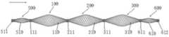
图1是实施例1提供的节段式膨胀部件的结构示意图;Fig. 1 is a schematic structural view of the segmental expansion part provided in Example 1;
图2是第一可膨胀部100的结构示意图;FIG. 2 is a schematic structural view of the first
图3是实施例10提供的节段式膨胀部件的结构示意图。Fig. 3 is a schematic structural diagram of the segmental expansion part provided in Embodiment 10.
具体实施方式Detailed ways
以下结合具体实施方式对本发明的技术方案做进一步地的解释说明但应该说明的是,具体实施方式只是对本发明技术方案实质的一种具体化的实施和解释,不应该理解为是对本发明保护范围的一种限制。The technical solution of the present invention will be further explained below in conjunction with the specific embodiments. a limitation of .
下面结合附图和实施例对本申请作进一步的详细说明。可以理解的是,此处所描述的具体实施例仅仅用于解释相关发明,而非对该发明的限定。另外还需要说明的是,为了便于描述,附图中仅示出了与有关发明相关的部分。The application will be further described in detail below in conjunction with the accompanying drawings and embodiments. It should be understood that the specific embodiments described here are only used to explain related inventions, rather than to limit the invention. It should also be noted that, for the convenience of description, only the parts related to the related invention are shown in the drawings.
在本申请的描述中,需要说明的是,除非另有明确的规定和限定,术语“安装”、“相连”、“连接”等应做广义理解,例如,可以是固定连接,也可以是可拆卸连接,或一体地连接;可以是机械连接,也可以是电连接;可以是直接相连,也可以通过中间媒介间接相连。对于本领域的普通技术人员而言,可以根据具体情况理解上述术语在本申请中的具体含义。In the description of this application, it should be noted that, unless otherwise clearly specified and limited, the terms "installation", "connection", "connection" and so on should be understood in a broad sense, for example, it can be a fixed connection or a flexible connection. Detachable connection, or integral connection; it can be mechanical connection or electrical connection; it can be direct connection or indirect connection through an intermediary. Those of ordinary skill in the art can understand the specific meanings of the above terms in this application according to specific situations.
在本申请的描述中,需要理解的是,文中术语“远端”和“近端”应当被理解为从手术操作者的方向观察,“远端”是远离手术操作者的一端,而“近端”是靠近手术操作者的一端。文中术语“轴向”应当被理解为支架推送方向或导丝的长度方向,“径向”应当被理解为“轴向”的垂直方向。In the description of the present application, it should be understood that the terms "distal end" and "proximal end" should be understood as viewed from the direction of the operator, "distal end" is the end away from the operator, and "near end" is the end far away from the operator. "end" is the end near the operator. The term "axial" herein should be understood as the direction in which the stent is pushed or the length direction of the guide wire, and "radial" should be understood as the direction perpendicular to the "axial".
在本申请的描述中,需要说明的是,在不冲突的情况下,本申请中的实施例及实施例中的特征可以相互组合。In the description of the present application, it should be noted that, in the case of no conflict, the embodiments in the present application and the features in the embodiments can be combined with each other.
实施例1Example 1
一种节段式膨胀部件,用18根直径为0.046mm的镍钛诺合金丝作为编织丝线,在直径为3.5mm的芯轴上,按照PPI为85进行编织,编织方式为两上两下的编织方式(具体为:一根经线与交叉在所述一根经线上的四根相邻的纬线为一组织线,所述一组织线中包括四个织点,分别为两个正织点、两个反织点,其中所述两个正织点相邻或所述两个反织点相邻),在520℃下保温5min进行热定型,撤去芯轴后,获得长度为60mm的网管状结构;A segmental expansion part, using 18 nitinol alloy wires with a diameter of 0.046mm as braided wires, braiding on a mandrel with a diameter of 3.5mm according to a PPI of 85, and the braiding method is two up and two down The weaving method (specifically: a warp thread and four adjacent weft threads intersecting on the one warp thread is a weaving line, and the one weaving line includes four weaving points, which are respectively two positive weaving points, Two reverse weaving points, wherein the two positive weaving points are adjacent or the two reverse weaving points are adjacent), heat setting at 520°C for 5 minutes, and after the mandrel is removed, a network tubular shape with a length of 60mm is obtained. structure;
将所述网管状结构(自然状态)按照每8mm进行4段节段,并在节段处进行束缚,束缚方式是在所述节段近端起始部内部焊接设置外径为0.41mm,长度为0.5mm的铂合金圆柱体(显影部件),获得节段式膨胀部件(可膨胀部的轴向长度与近端束缚部的轴向长度之比为15:1);所述可膨胀部膨胀后的外径尺寸为2.5mm,且A点与B点的连线与轴向的夹角为15.58°。The mesh-like structure (natural state) is divided into 4 sections every 8 mm, and restrained at the segments. The restraint method is to weld the inner part of the proximal end of the segment with an outer diameter of 0.41 mm and a length of 0.41 mm. is a 0.5 mm platinum alloy cylinder (developing part), obtaining a segmental expansion part (the ratio of the axial length of the expandable part to the axial length of the proximal tethering part is 15:1); the expandable part expands The final outer diameter is 2.5mm, and the angle between the line connecting point A and point B and the axial direction is 15.58°.
实施例2Example 2
与实施例1的区别仅在于改变网管状结构的节段比例为按照每6mm进行5段节段(可膨胀部的轴向长度与近端束缚部的轴向长度之比为11:1)。The difference from Example 1 is only that the segment ratio of the network tubular structure is changed to 5 segments per 6 mm (the ratio of the axial length of the expandable part to the axial length of the proximal binding part is 11:1).
实施例2得到的节段式膨胀部件可膨胀部膨胀后的外径尺寸为2.3mm;且A点与B点的连线与轴向的夹角为18.97°。The expanded outer diameter of the expandable part of the segmental expandable part obtained in Example 2 is 2.3 mm; and the angle between the line connecting point A and point B and the axial direction is 18.97°.
实施例3Example 3
与实施例1的区别仅在于改变网管状结构的节段比例为按照每10.5mm进行3段节段(可膨胀部的轴向长度与近端束缚部的轴向长度之比为20:1)。The difference from Example 1 is only that the segmental ratio of the network tubular structure is changed to 3 segments per 10.5 mm (the ratio of the axial length of the expandable part to the axial length of the proximal binding part is 20:1) .
实施例3得到的节段式膨胀部件的可膨胀部膨胀后的外径尺寸为2.7mm;且A点与B点的连线与轴向的夹角为12.90°。The expanded outer diameter of the expandable part of the segmental expandable component obtained in Example 3 is 2.7 mm; and the angle between the line connecting point A and point B and the axial direction is 12.90°.
实施例4~6Embodiment 4~6
与实施例1的区别仅在于改变网管状结构的编织密度PPI为50(实施例4)、120(实施例5)、200(实施例6)。The difference from Example 1 is only that the weaving density PPI of the network tubular structure is changed to 50 (Example 4), 120 (Example 5), and 200 (Example 6).
实施例7Example 7
一种节段式膨胀部件,用18根直径为0.046mm的镍钛诺合金丝作为编织丝线,在直径为3.5mm的芯轴上,按照PPI为85进行编织,编织方式为两上两下的编织方式(具体为:一根经线与交叉在所述一根经线上的四根相邻的纬线为一组织线,所述一组织线中包括四个织点,分别为两个正织点、两个反织点,其中所述两个正织点相邻或所述两个反织点相邻),在520℃下保温5min进行热定型,撤去芯轴后,获得长度为80mm的网管状结构;A segmental expansion part, using 18 nitinol alloy wires with a diameter of 0.046mm as braided wires, braiding on a mandrel with a diameter of 3.5mm according to a PPI of 85, and the braiding method is two up and two down The weaving method (specifically: a warp thread and four adjacent weft threads intersecting on the one warp thread is a weaving line, and the one weaving line includes four weaving points, which are respectively two positive weaving points, Two reverse weaving points, wherein the two positive weaving points are adjacent or the two reverse weaving points are adjacent), heat setting at 520°C for 5 minutes, and after removing the mandrel, a network tubular shape with a length of 80mm is obtained. structure;
将所述网管状结构(自然状态)按照每8mm进行6段节段,并在节段处进行束缚,束缚方式是在所述节段近端起始部内部焊接设置外径为0.41mm,长度为0.5mm的铂合金圆柱体,获得节段式膨胀部件(可膨胀部的轴向长度与近端束缚部的轴向长度之比为15:1);所述可膨胀部膨胀后的外径尺寸为2.5mm,且A点与B点的连线与轴向的夹角为15.58°。The mesh-like structure (natural state) is divided into 6 segments every 8mm, and restrained at the segments. The restraint method is to weld the inner part of the proximal end of the segment to set the outer diameter to 0.41mm, and the length A platinum alloy cylinder of 0.5 mm to obtain a segmental expansion part (the ratio of the axial length of the expandable part to the axial length of the proximal binding part is 15:1); the outer diameter of the expandable part after expansion The size is 2.5mm, and the angle between the line connecting point A and point B and the axial direction is 15.58°.
实施例8Example 8
与实施例1的区别在于一种节段式膨胀部件,用16根直径为0.09mm的镍钛诺合金丝作为编织丝线,在直径为4.5mm的芯轴上,按照PPI为30进行编织,编织方式为两上两下的编织方式(具体为:一根经线与交叉在所述一根经线上的四根相邻的纬线为一组织线,所述一组织线中包括四个织点,分别为两个正织点、两个反织点,其中所述两个正织点相邻或所述两个反织点相邻),在530℃下保温6min进行热定型,撤去芯轴后,获得长度为80mm的网管状结构;The difference from Example 1 is that a segmental expansion part uses 16 nitinol alloy wires with a diameter of 0.09mm as the braided wires, and braids on a mandrel with a diameter of 4.5mm according to a PPI of 30. The method is a two-up and two-down weaving method (specifically: one warp thread and four adjacent weft threads crossing the one warp thread are a weaving line, and the one weaving line includes four weaving points, respectively It is two positive weaving points and two reverse weaving points, wherein the two positive weaving points are adjacent or the two reverse weaving points are adjacent), heat setting at 530°C for 6 minutes, and after removing the mandrel, Obtain a network tubular structure with a length of 80 mm;
将所述网管状结构(自然状态)按照每12mm进行4段节段,并在节段处进行束缚,束缚方式是在所述节段近端起始部内部焊接设置外径为0.5mm,长度为0.6mm的铂合金圆柱体,获得节段式膨胀部件(可膨胀部的轴向长度与近端束缚部的轴向长度之比为19:1);所述可膨胀部膨胀后的外径尺寸为3.7mm,且A点与B点的连线与轴向的夹角为15.69°。The mesh-like structure (natural state) is divided into 4 sections every 12 mm, and restrained at the segments. The restraint method is to weld the inner part of the proximal end of the segment with an outer diameter of 0.5 mm and a length of 0.5 mm. A platinum alloy cylinder of 0.6 mm to obtain a segmental expansion part (the ratio of the axial length of the expandable part to the axial length of the proximal binding part is 19:1); the outer diameter of the expandable part after expansion The size is 3.7mm, and the angle between the line connecting point A and point B and the axial direction is 15.69°.
实施例9Example 9
与实施例1的区别在于一种节段式膨胀部件,用16根直径为0.09mm的镍钛诺合金丝作为编织丝线,在直径为4.5mm的芯轴上,按照PPI为30进行编织,编织方式为两上两下的编织方式(具体为:一根经线与交叉在所述一根经线上的四根相邻的纬线为一组织线,所述一组织线中包括四个织点,分别为两个正织点、两个反织点,其中所述两个正织点相邻或所述两个反织点相邻),在530℃下保温6min进行热定型,撤去芯轴后,获得长度为80mm的网管状结构;The difference from Example 1 is that a segmental expansion part uses 16 nitinol alloy wires with a diameter of 0.09mm as the braided wires, and braids on a mandrel with a diameter of 4.5mm according to a PPI of 30. The method is a two-up and two-down weaving method (specifically: one warp thread and four adjacent weft threads crossing the one warp thread are a weaving line, and the one weaving line includes four weaving points, respectively It is two positive weaving points and two reverse weaving points, wherein the two positive weaving points are adjacent or the two reverse weaving points are adjacent), heat setting at 530°C for 6 minutes, and after removing the mandrel, Obtain a network tubular structure with a length of 80 mm;
将所述网管状结构(自然状态)按照每5.5mm进行9段节段,并在节段处进行束缚,束缚方式是在所述节段近端起始部内部焊接设置外径为0.5mm,长度为0.6mm的铂合金圆柱体,获得节段式膨胀部件(可膨胀部的轴向长度与近端束缚部的轴向长度之比为8:1);所述可膨胀部膨胀后的外径尺寸为3.5mm,且A点与B点的连线与轴向的夹角为28.62°。The mesh-like structure (natural state) is divided into 9 segments every 5.5 mm, and restrained at the segments. The restraint method is to weld the inner part of the proximal end of the segment with an outer diameter of 0.5 mm. Platinum alloy cylinder with a length of 0.6 mm to obtain a segmental expansion part (the ratio of the axial length of the expandable part to the axial length of the proximal binding part is 8:1); the expanded outer part of the expandable part The diameter is 3.5mm, and the angle between the line connecting point A and point B and the axial direction is 28.62°.
实施例1~实施例9具有相似的结构,以实施例1为例,得到的节段式膨胀部件的具体结构示意如图1所示(图1为实施例1提供的节段式膨胀部件的结构示意图)具有4个节段式膨胀单元,第一节段式膨胀单元100包括第一可膨胀部110,连接在所述第一可膨胀部110近端的第一近端束缚部111;第二节段式膨胀单元200包括第二可膨胀部210,连接在第二可膨胀部210近端的第二近端束缚部211;第三节段式膨胀单元300包括第三可膨胀部310,连接在第三可膨胀部310近端的第三近端束缚部311;第四节段式膨胀单元400包括第四可膨胀部410,连接在所述第四可膨胀部410近端的第四近端束缚部411,第四节段式膨胀单元400的远端束缚部为第一远端束缚部412;Examples 1 to 9 have similar structures. Taking Example 1 as an example, the specific structure of the obtained segmental expansion part is shown in Figure 1 (Figure 1 is the segmental expansion part provided in Example 1. Structural schematic diagram) has four segmental expansion units, the first
且第一节段式膨胀单元100的远端束缚部为第二近端束缚部211,第二节段式膨胀单元200的远端束缚部为第三近端束缚部311,第三节段式膨胀单元300的远端束缚部为第四近端束缚部411。And the distal binding part of the first
图1中,箭头方向为由近端指向远端。In Figure 1, the direction of the arrow is from the proximal end to the distal end.
如图2(图2为第一可膨胀部100的结构示意图)所示,以第一可膨胀部100为例,其在膨胀状态下,沿同一轴截面,可膨胀部100轴向长度的中心点向可膨胀部腔壁内侧的投影点为A点,近端束缚部与可膨胀部的腔壁内侧交点为B点,远端束缚部与可膨胀部的腔壁内侧交点为B’点。As shown in Fig. 2 (Fig. 2 is a schematic structural diagram of the first expandable part 100), taking the first
实施例10Example 10
一种节段式膨胀部件,用18根直径为0.046mm的镍钛诺合金丝作为编织金属丝线,在直径为3.5mm的芯轴上,按照PPI为85进行编织,编织方式为两上两下的编织方式(具体为:一根经线与交叉在所述一根经线上的四根相邻的纬线为一组织线,所述一组织线中包括四个织点,分别为两个正织点、两个反织点,其中所述两个正织点相邻或所述两个反织点相邻),在520℃下保温5min进行热定型,撤去芯轴后,获得长度为60mm的网管状结构;A segmental expansion part, using 18 Nitinol alloy wires with a diameter of 0.046mm as braided metal wires, on a mandrel with a diameter of 3.5mm, weaving according to the PPI of 85, the braiding method is two up and two down The weaving method (specifically: one warp thread and four adjacent weft threads intersecting on the one warp thread is a weaving line, and the one weaving line includes four weaving points, which are respectively two positive weaving points , two reverse weaving points, wherein the two positive weaving points are adjacent or the two reverse weaving points are adjacent), heat setting at 520°C for 5 minutes, and after the mandrel is removed, a net with a length of 60mm is obtained tubular structure;
将所述网管状结构(自然状态)按照第一段4mm、第二段8mm、第三段8mm、第四段8mm、第五段4mm进行节段,并在节段处进行束缚,束缚方式是在所述节段近端起始部内部焊接设置外径为0.41mm,长度为0.5mm的铂合金圆柱体,获得节段式膨胀部件,第一段和第五段外径为0.9mm,第二段、第三段和第四段外径为2.5mm;且第一段和第五段的过渡角为7.97°,第二段、第三段和第四段的A点与B点的连线与轴向的夹角为15.58°。The network tubular structure (natural state) is segmented according to the first segment of 4mm, the second segment of 8mm, the third segment of 8mm, the fourth segment of 8mm, and the fifth segment of 4mm, and restraint at the segments. The restraint method is A platinum alloy cylinder with an outer diameter of 0.41 mm and a length of 0.5 mm is welded inside the starting part of the proximal end of the segment to obtain a segmental expansion part. The first and fifth segments have an outer diameter of 0.9 mm. The outer diameter of the second, third and fourth sections is 2.5mm; and the transition angle between the first and fifth sections is 7.97°, the connection between point A and point B of the second, third and fourth sections The angle between the line and the axial direction is 15.58°.
实施例10得到的节段式膨胀部件的具体结构示意如图3所示(图3为实施例10提供的节段式膨胀部件的结构示意图)具有5个节段,由近及远依次为第一力传导辅助部件500,包括第一网管状可膨胀结构510,连接在所述网管状可膨胀结构510近端的第五近端束缚部511;第一节段式膨胀单元100包括第一可膨胀部110,连接在所述第一可膨胀部110近端的第一近端束缚部111;第二节段式膨胀单元200包括第二可膨胀部210,连接在第二可膨胀部210近端的第二近端束缚部211;第三节段式膨胀单元300包括第三可膨胀部310,连接在第三可膨胀部310近端的第三近端束缚部311;第二力传导辅助部件600,包括第二网管状可膨胀结构610,连接在所述网管状可膨胀结构610近端的第六近端束缚部611,第二力传导辅助部件600的远端束缚部为第二远端束缚部612;The specific structural diagram of the segmental expansion part obtained in Example 10 is shown in Figure 3 (Figure 3 is the structural schematic diagram of the segmental expansion part provided in Example 10). A force conduction
且第一网管状可膨胀结构510的远端束缚部为第一近端束缚部111,第一节段式膨胀单元100的远端束缚部为第二近端束缚部211,第二节段式膨胀单元200的远端束缚部为第三近端束缚部311,第三节段式膨胀单元300的远端束缚部为第六近端束缚部611。And the distal binding part of the first net tubular
图3中,箭头方向为由近端指向远端。In Fig. 3, the direction of the arrow is from the proximal end to the distal end.
实施例11Example 11
一种节段式膨胀部件,用18根直径为0.046mm的镍钛诺合金丝作为编织金属丝线,在直径为3.5mm的芯轴上,按照PPI为85进行编织,编织方式为两上两下的编织方式(具体为:一根经线与交叉在所述一根经线上的四根相邻的纬线为一组织线,所述一组织线中包括四个织点,分别为两个正织点、两个反织点,其中所述两个正织点相邻或所述两个反织点相邻),在520℃下保温5min进行热定型,撤去芯轴后,获得长度为60mm的网管状结构;A segmental expansion part, using 18 Nitinol alloy wires with a diameter of 0.046mm as braided metal wires, on a mandrel with a diameter of 3.5mm, weaving according to the PPI of 85, the braiding method is two up and two down The weaving method (specifically: one warp thread and four adjacent weft threads intersecting on the one warp thread is a weaving line, and the one weaving line includes four weaving points, which are respectively two positive weaving points , two reverse weaving points, wherein the two positive weaving points are adjacent or the two reverse weaving points are adjacent), heat setting at 520°C for 5 minutes, and after the mandrel is removed, a net with a length of 60mm is obtained tubular structure;
将所述网管状结构(自然状态)按照第一段1mm、第二段3mm、第三段8mm、第四段8mm、第五段8mm、第六段4mm进行节段,并在节段处进行束缚,束缚方式是在所述节段近端起始部内部焊接设置外径为0.41mm,长度为0.5mm的铂合金圆柱体,获得节段式膨胀部件,第一段外径为0.42mm,第二段外径为0.6mm、第三段、第四段和第五段外径为2.5mm、第六段外径为0.9mm;第一段过渡角为1.14°,第二段过渡角为4.35°;第三段、第四段和第五段的A点与B点的连线与轴向的夹角仍为15.58°,第六段过渡角为7.97°。Segment the network tubular structure (natural state) according to the first segment 1mm, the second segment 3mm, the third segment 8mm, the fourth segment 8mm, the fifth segment 8mm, and the sixth segment 4mm, and perform Constraint, the restraint method is to weld a platinum alloy cylinder with an outer diameter of 0.41 mm and a length of 0.5 mm inside the starting part of the proximal end of the segment to obtain a segmental expansion part. The outer diameter of the first segment is 0.42 mm. The outer diameter of the second section is 0.6mm, the outer diameter of the third section, the fourth section and the fifth section is 2.5mm, and the outer diameter of the sixth section is 0.9mm; the transition angle of the first section is 1.14°, and the transition angle of the second section is 4.35°; the angle between the line connecting point A and point B of the third, fourth, and fifth sections and the axial direction is still 15.58°, and the transition angle of the sixth section is 7.97°.
实施例12Example 12
一种节段式膨胀部件,用18根直径为0.046mm的镍钛诺合金丝作为编织金属丝线,在直径为6mm的芯轴上,按照PPI为85进行编织,编织方式为两上两下的编织方式(具体为:一根经线与交叉在所述一根经线上的四根相邻的纬线为一组织线,所述一组织线中包括四个织点,分别为两个正织点、两个反织点,其中所述两个正织点相邻或所述两个反织点相邻),在520℃下保温5min进行热定型,撤去芯轴后,获得长度为60mm的网管状结构;A segmental expansion part, using 18 nitinol alloy wires with a diameter of 0.046mm as braided metal wires, braiding on a mandrel with a diameter of 6mm according to a PPI of 85, and the braiding method is two up and two down The weaving method (specifically: a warp thread and four adjacent weft threads intersecting on the one warp thread is a weaving line, and the one weaving line includes four weaving points, which are respectively two positive weaving points, Two reverse weaving points, wherein the two positive weaving points are adjacent or the two reverse weaving points are adjacent), heat setting at 520°C for 5 minutes, and after the mandrel is removed, a network tubular shape with a length of 60mm is obtained. structure;
将所述网管状结构(自然状态)按照每8mm进行4段节段,并在节段处进行束缚,束缚方式是在所述节段近端起始部内部焊接设置外径为0.41mm,长度为0.5mm的铂合金圆柱体,获得节段式膨胀部件(可膨胀部的轴向长度与近端束缚部的轴向长度之比为15:1);所述可膨胀部膨胀后的外径尺寸为5.3mm,且A点与B点的连线与轴向的夹角为33.12°。The mesh-like structure (natural state) is divided into 4 sections every 8 mm, and restrained at the segments. The restraint method is to weld the inner part of the proximal end of the segment with an outer diameter of 0.41 mm and a length of 0.41 mm. A platinum alloy cylinder of 0.5 mm to obtain a segmental expansion part (the ratio of the axial length of the expandable part to the axial length of the proximal binding part is 15:1); the outer diameter of the expandable part after expansion The size is 5.3mm, and the angle between the line connecting point A and point B and the axial direction is 33.12°.
对比例1Comparative example 1
与实施例1的区别仅在于改变网管状结构的编织密度PPI为15。The difference from Example 1 is only that the weaving density PPI of the network tubular structure is changed to 15.
对比例2Comparative example 2
一种节段式膨胀部件,用18根直径为0.046mm的镍钛诺合金丝作为编织金属丝线,在直径为3.5mm的芯轴上,按照PPI为85进行编织,编织方式为两上两下的编织方式(具体为:一根经线与交叉在所述一根经线上的四根相邻的纬线为一组织线,所述一组织线中包括四个织点,分别为两个正织点、两个反织点,其中所述两个正织点相邻或所述两个反织点相邻),在520℃下保温5min进行热定型,撤去芯轴后,获得长度为60mm的网管状结构;A segmental expansion part, using 18 Nitinol alloy wires with a diameter of 0.046mm as braided metal wires, on a mandrel with a diameter of 3.5mm, weaving according to the PPI of 85, the braiding method is two up and two down The weaving method (specifically: one warp thread and four adjacent weft threads intersecting on the one warp thread is a weaving line, and the one weaving line includes four weaving points, which are respectively two positive weaving points , two reverse weaving points, wherein the two positive weaving points are adjacent or the two reverse weaving points are adjacent), heat setting at 520°C for 5 minutes, and after the mandrel is removed, a net with a length of 60mm is obtained tubular structure;
将所述网管状结构(自然状态)按照每3mm进行10段节段,并在节段处进行束缚,束缚方式是在所述节段近端起始部内部焊接设置外径为0.41mm,长度为0.5mm的铂合金圆柱体,获得节段式膨胀部件(可膨胀部的轴向长度与近端束缚部的轴向长度之比为5:1);所述可膨胀部膨胀后的尺寸为0.6mm,且A点与B点的连线与轴向的夹角为4.35°。The net tubular structure (natural state) is divided into 10 segments every 3mm, and restrained at the segment. The restraint method is to weld the inner part of the proximal end of the segment with an outer diameter of 0.41 mm and a length of 0.41 mm. A platinum alloy cylinder of 0.5 mm was used to obtain a segmental expansion part (the ratio of the axial length of the expandable part to the axial length of the proximal binding part was 5:1); the expanded size of the expandable part was 0.6mm, and the angle between the line connecting point A and point B and the axial direction is 4.35°.
对比例3Comparative example 3
一种节段式膨胀部件,用18根直径为0.046mm的镍钛诺合金丝作为编织金属丝线,在直径为3.5mm的芯轴上,按照PPI为85进行编织,编织方式为两上两下的编织方式(具体为:一根经线与交叉在所述一根经线上的四根相邻的纬线为一组织线,所述一组织线中包括四个织点,分别为两个正织点、两个反织点,其中所述两个正织点相邻或所述两个反织点相邻),在520℃下保温5min进行热定型,撤去芯轴后,获得长度为60mm的网管状结构;A segmental expansion part, using 18 Nitinol alloy wires with a diameter of 0.046mm as braided metal wires, on a mandrel with a diameter of 3.5mm, weaving according to the PPI of 85, the braiding method is two up and two down The weaving method (specifically: one warp thread and four adjacent weft threads intersecting on the one warp thread is a weaving line, and the one weaving line includes four weaving points, which are respectively two positive weaving points , two reverse weaving points, wherein the two positive weaving points are adjacent or the two reverse weaving points are adjacent), heat setting at 520°C for 5 minutes, and after the mandrel is removed, a net with a length of 60mm is obtained tubular structure;
将所述网管状结构(自然状态)按照每12.5mm进行2段节段,并在节段处进行束缚,束缚方式是在所述节段近端起始部内部焊接设置外径为0.41mm,长度为0.5mm的铂合金圆柱体,获得节段式膨胀部件(可膨胀部的轴向长度与近端束缚部的轴向长度之比为24:1);所述可膨胀部膨胀后的尺寸为0.6mm,且A点与B点的连线与轴向的夹角为11.73°。The mesh-like structure (natural state) is divided into 2 segments every 12.5 mm, and restrained at the segment. The restraint method is to weld the inner part of the proximal end of the segment to set the outer diameter to 0.41 mm. Platinum alloy cylinder with a length of 0.5 mm to obtain a segmental expandable part (the ratio of the axial length of the expandable part to the axial length of the proximal tethering part is 24:1); the expanded size of the expandable part is 0.6mm, and the angle between the line connecting point A and point B and the axial direction is 11.73°.
性能测试:Performance Testing:
将实施例和对比例的节段式膨胀部件近端与100cm的推送导丝远端固定连接,获得测试样品,用于进行如下性能测试。The proximal ends of the segmental expansion components of the examples and the comparative examples were fixedly connected with the distal ends of a 100 cm pushing guide wire to obtain test samples for the following performance tests.
(1)跟踪性:将测试样品推送进入跟踪性测试夹具,记录是否可以顺利过弯;所述跟踪性测试夹具包括共面的进入通道和具有弯曲路径的血管模型,弯曲路径包括4个曲率半径是2mm的半圆形交替曲线。(1) Trackability: push the test sample into the trackability test fixture, and record whether it can go through the bend smoothly; the trackability test fixture includes a coplanar access channel and a blood vessel model with a curved path, and the curved path includes 4 curvature radii It is a semicircular alternating curve of 2mm.
(2)远端力值:将测试样品置于直线的血管模型中,近端施加200mN的力,利用全模块推送回撤力仪监测远端的力值。(2) Distal force value: place the test sample in a linear blood vessel model, apply a force of 200mN at the proximal end, and monitor the distal force value with a full-module push-back force meter.
(3)径向支撑力:使用径向支撑力测试仪(MSI RS550),在温度37±2℃下,使夹具的初始直径为5.5mm,然后将所述节段式膨胀部件的可膨胀部置于夹具内,然后使夹具直径以0.1mm/s的速率逐渐缩小到0.4mm,然后以0.1mm/s的速率逐渐扩张到5.5mm,记录变化过程中的最大力数值。(3) Radial support force: use a radial support force tester (MSI RS550), at a temperature of 37±2°C, make the initial diameter of the fixture 5.5mm, and then place the expandable part of the segmental expansion part Put it in the fixture, then gradually reduce the diameter of the fixture to 0.4mm at a rate of 0.1mm/s, and then gradually expand to 5.5mm at a rate of 0.1mm/s, and record the maximum force value during the change process.
测试结果见表1。The test results are shown in Table 1.
表1 性能测试结果Table 1 Performance test results
从表1可以看出,本申请提供的节段式膨胀部件均能够顺利通过4个曲率半径是2mm的半圆形交替曲线形成的预定弯型,且近端施加200mN的推送力,远端能够维持3~6mN的较小的远端轴向推力,并保持合适的径向支撑力。It can be seen from Table 1 that the segmental expansion parts provided by the present application can smoothly pass through the predetermined curved shape formed by four semicircular alternating curves with a radius of curvature of 2mm, and a pushing force of 200mN is applied at the proximal end, and the distal end can Maintain a small distal axial thrust of 3-6mN, and maintain an appropriate radial support force.
表1中,对比例1由于可膨胀部,每英寸长度内的交叉点个数过小,轴向推力和径向支撑力过小,无法通过具有弯曲路径的血管模型;对比例2由于可膨胀部的轴向长度与近端束缚部的轴向长度之比过小,柔顺性变差,无法通过具有弯曲路径的血管模型;而对比例3由于可膨胀部的轴向长度与近端束缚部的轴向长度之比过大,轴向推力过小,无法通过具有弯曲路径的血管模型。In Table 1, due to the expandable part, the number of intersections per inch in Comparative Example 1 is too small, and the axial thrust and radial support force are too small to pass through the vascular model with a curved path; Comparative Example 2 due to the expandable The ratio of the axial length of the expandable part to the axial length of the proximal binding part is too small, the flexibility becomes poor, and it is impossible to pass through the blood vessel model with a curved path; The axial length ratio of is too large and the axial thrust is too small to pass through a vessel model with a tortuous path.
最后应说明的是:以上各实施例仅用以说明本发明的技术方案,而非对其限制;尽管参照前述各实施例对本发明进行了详细的说明,本领域的普通技术人员应当理解:其依然可以对前述各实施例所记载的技术方案进行修改,或者对其中部分或者全部技术特征进行等同替换;而这些修改或者替换,并不使相应技术方案的本质脱离本发明各实施例技术方案的范围。Finally, it should be noted that: the above embodiments are only used to illustrate the technical solutions of the present invention, rather than limiting them; although the present invention has been described in detail with reference to the foregoing embodiments, those of ordinary skill in the art should understand that: It is still possible to modify the technical solutions described in the foregoing embodiments, or perform equivalent replacements for some or all of the technical features; and these modifications or replacements do not make the essence of the corresponding technical solutions deviate from the technical solutions of the various embodiments of the present invention. scope.
Claims (12)
Priority Applications (3)
| Application Number | Priority Date | Filing Date | Title |
|---|---|---|---|
| CN202310302571.XACN115998496B (en) | 2023-03-27 | 2023-03-27 | Segmented expansion member, delivery device and vascular implant system incorporating the same |
| PCT/CN2023/122393WO2024198292A1 (en) | 2023-03-27 | 2023-09-28 | Segmental expansion component, and delivery device and vascular implant system comprising same |
| KR1020257028289AKR20250136907A (en) | 2023-03-27 | 2023-09-28 | Segmented expandable member, transport device including same, and vascular implant system |
Applications Claiming Priority (1)
| Application Number | Priority Date | Filing Date | Title |
|---|---|---|---|
| CN202310302571.XACN115998496B (en) | 2023-03-27 | 2023-03-27 | Segmented expansion member, delivery device and vascular implant system incorporating the same |
Publications (2)
| Publication Number | Publication Date |
|---|---|
| CN115998496A CN115998496A (en) | 2023-04-25 |
| CN115998496Btrue CN115998496B (en) | 2023-05-26 |
Family
ID=86027087
Family Applications (1)
| Application Number | Title | Priority Date | Filing Date |
|---|---|---|---|
| CN202310302571.XAActiveCN115998496B (en) | 2023-03-27 | 2023-03-27 | Segmented expansion member, delivery device and vascular implant system incorporating the same |
Country Status (3)
| Country | Link |
|---|---|
| KR (1) | KR20250136907A (en) |
| CN (1) | CN115998496B (en) |
| WO (1) | WO2024198292A1 (en) |
Families Citing this family (1)
| Publication number | Priority date | Publication date | Assignee | Title |
|---|---|---|---|---|
| CN115998496B (en)* | 2023-03-27 | 2023-05-26 | 艾柯医疗器械(北京)股份有限公司 | Segmented expansion member, delivery device and vascular implant system incorporating the same |
Citations (4)
| Publication number | Priority date | Publication date | Assignee | Title |
|---|---|---|---|---|
| CN206491831U (en)* | 2016-11-08 | 2017-09-15 | 吕怡然 | Stent pushing system and corresponding blood flow guider |
| CN108056798A (en)* | 2016-11-08 | 2018-05-22 | 吕怡然 | Stent pushing system and corresponding blood flow guider and blood flow guider assembly method |
| CN114848247A (en)* | 2020-10-30 | 2022-08-05 | 艾柯医疗器械(北京)有限公司 | Bead string component, method for the production thereof and use thereof |
| CN115137536A (en)* | 2022-09-05 | 2022-10-04 | 艾柯医疗器械(北京)股份有限公司 | Bead string-shaped component, stent conveying system comprising same and stent system |
Family Cites Families (10)
| Publication number | Priority date | Publication date | Assignee | Title |
|---|---|---|---|---|
| EP2226040A1 (en)* | 2003-03-26 | 2010-09-08 | Cardiomind, Inc. | Stent delivery system with torsionally compressed stent |
| US20090112251A1 (en)* | 2007-07-25 | 2009-04-30 | Aga Medical Corporation | Braided occlusion device having repeating expanded volume segments separated by articulation segments |
| US20120172973A1 (en)* | 2010-12-30 | 2012-07-05 | Cook Medical Technologies Llc | Self-expanding occlusion device |
| CN105228688B (en)* | 2013-03-15 | 2019-02-19 | 伊瑟拉医疗公司 | Vascular treatment devices and methods |
| EP3092981A1 (en)* | 2015-05-12 | 2016-11-16 | VasDeBlock medical ApS | Occlusion device for reversible occlusion of a biological tube |
| DE102020115600A1 (en)* | 2020-06-12 | 2021-12-16 | Phenox Gmbh | Implant for the treatment of aneurysms |
| CN113925652A (en)* | 2021-09-30 | 2022-01-14 | 艾柯医疗器械(北京)有限公司 | Mechanical balloon, stent conveying device and stent system |
| CN115670763B (en)* | 2022-12-30 | 2023-04-07 | 艾柯医疗器械(北京)股份有限公司 | Stent delivery member, stent delivery system, and stent system |
| CN115670764B (en)* | 2023-01-04 | 2023-03-10 | 艾柯医疗器械(北京)股份有限公司 | Tubular implant delivery member, delivery system and stent system |
| CN115998496B (en)* | 2023-03-27 | 2023-05-26 | 艾柯医疗器械(北京)股份有限公司 | Segmented expansion member, delivery device and vascular implant system incorporating the same |
- 2023
- 2023-03-27CNCN202310302571.XApatent/CN115998496B/enactiveActive
- 2023-09-28WOPCT/CN2023/122393patent/WO2024198292A1/enactivePending
- 2023-09-28KRKR1020257028289Apatent/KR20250136907A/enactivePending
Patent Citations (4)
| Publication number | Priority date | Publication date | Assignee | Title |
|---|---|---|---|---|
| CN206491831U (en)* | 2016-11-08 | 2017-09-15 | 吕怡然 | Stent pushing system and corresponding blood flow guider |
| CN108056798A (en)* | 2016-11-08 | 2018-05-22 | 吕怡然 | Stent pushing system and corresponding blood flow guider and blood flow guider assembly method |
| CN114848247A (en)* | 2020-10-30 | 2022-08-05 | 艾柯医疗器械(北京)有限公司 | Bead string component, method for the production thereof and use thereof |
| CN115137536A (en)* | 2022-09-05 | 2022-10-04 | 艾柯医疗器械(北京)股份有限公司 | Bead string-shaped component, stent conveying system comprising same and stent system |
Also Published As
| Publication number | Publication date |
|---|---|
| KR20250136907A (en) | 2025-09-16 |
| WO2024198292A1 (en) | 2024-10-03 |
| CN115998496A (en) | 2023-04-25 |
Similar Documents
| Publication | Publication Date | Title |
|---|---|---|
| US6361558B1 (en) | Stent aneurysm treatment system and method | |
| JP4500550B2 (en) | Hybrid stent and method for manufacturing the same | |
| US6007574A (en) | Stent | |
| AU2018253740B2 (en) | Braid expansion ring with markers | |
| US9687245B2 (en) | Occlusive devices and methods of use | |
| KR101845115B1 (en) | Stent | |
| JP2021087772A (en) | Intrasaccular inverting braid with highly flexible fill material | |
| AU2014201193A1 (en) | Braided stent with expansion ring and method of delivery | |
| KR20040106533A (en) | Shape memory polymer stent | |
| CN104487024A (en) | Stent and stent delivery device | |
| JP2002136523A (en) | Foam substrate embolization apparatus and system | |
| KR101961530B1 (en) | Insertion and release system for implants | |
| CN115998496B (en) | Segmented expansion member, delivery device and vascular implant system incorporating the same | |
| US20150238195A1 (en) | Methods and systems for performing intralumenal procedures | |
| WO2022042347A1 (en) | Hemangioma occlusion apparatus, hemangioma occlusion and treatment apparatus, and hemangioma occlusion system | |
| US20130046326A1 (en) | Methods and systems for performing intralumenal procedures | |
| CN115245413A (en) | Cerebral artery stent conveying system | |
| CN115813628A (en) | Bead string-shaped component and support conveying component comprising same | |
| CN116035640A (en) | Medical implant and preparation method |
Legal Events
| Date | Code | Title | Description |
|---|---|---|---|
| PB01 | Publication | ||
| PB01 | Publication | ||
| SE01 | Entry into force of request for substantive examination | ||
| SE01 | Entry into force of request for substantive examination | ||
| GR01 | Patent grant | ||
| GR01 | Patent grant |