CN115998438A - Sterile adapter, sterile barrier and medical system - Google Patents
Sterile adapter, sterile barrier and medical systemDownload PDFInfo
- Publication number
- CN115998438A CN115998438ACN202111226052.7ACN202111226052ACN115998438ACN 115998438 ACN115998438 ACN 115998438ACN 202111226052 ACN202111226052 ACN 202111226052ACN 115998438 ACN115998438 ACN 115998438A
- Authority
- CN
- China
- Prior art keywords
- housing
- coupling
- sterile
- driving device
- surgical instrument
- Prior art date
- Legal status (The legal status is an assumption and is not a legal conclusion. Google has not performed a legal analysis and makes no representation as to the accuracy of the status listed.)
- Pending
Links
Images


Classifications
- A—HUMAN NECESSITIES
- A61—MEDICAL OR VETERINARY SCIENCE; HYGIENE
- A61B—DIAGNOSIS; SURGERY; IDENTIFICATION
- A61B34/00—Computer-aided surgery; Manipulators or robots specially adapted for use in surgery
- A61B34/30—Surgical robots
- A—HUMAN NECESSITIES
- A61—MEDICAL OR VETERINARY SCIENCE; HYGIENE
- A61B—DIAGNOSIS; SURGERY; IDENTIFICATION
- A61B46/00—Surgical drapes
- A61B46/10—Surgical drapes specially adapted for instruments, e.g. microscopes
Landscapes
- Health & Medical Sciences (AREA)
- Surgery (AREA)
- Life Sciences & Earth Sciences (AREA)
- Engineering & Computer Science (AREA)
- Biomedical Technology (AREA)
- Heart & Thoracic Surgery (AREA)
- Medical Informatics (AREA)
- Molecular Biology (AREA)
- Animal Behavior & Ethology (AREA)
- General Health & Medical Sciences (AREA)
- Public Health (AREA)
- Veterinary Medicine (AREA)
- Nuclear Medicine, Radiotherapy & Molecular Imaging (AREA)
- Robotics (AREA)
- Accommodation For Nursing Or Treatment Tables (AREA)
- Surgical Instruments (AREA)
Abstract
Translated fromChinese
Description
Translated fromChinese技术领域technical field
本发明涉及医疗设备技术领域,尤其涉及一种无菌适配器、无菌屏障以及医疗系统。The invention relates to the technical field of medical equipment, in particular to a sterile adapter, a sterile barrier and a medical system.
背景技术Background technique
机器人外科系统是一套复杂的系统,包含电子显示系统、机械臂及手术器械,其中机械臂具有一个或多个马达,可以基于来自操作者的命令在手术器械定位在患者体内的手术部位时致动该手术器械的一个和多个自由度。机械臂离患者较近,其无菌状态对手术成功非常重要,然而机械臂包含多个部件(例如马达、编码器、传感器等),使其实际上无法使用常规消毒方法诸如蒸汽或加热等进行消毒。一种维持无菌的解决方案是在机械臂与手术器械之间提供无菌屏障,隔离机械臂(非无菌)与手术器械(无菌),同时不干扰机械臂致动手术器械,并可在机械臂和手术器械之间传递简单信号如拆装信号等。A robotic surgical system is a complex system that includes an electronic display system, a robotic arm with one or more motors that, based on commands from One or more degrees of freedom to move the surgical instrument. The robotic arm is close to the patient, and its sterility is very important to the success of the operation, however the robotic arm contains multiple components (eg motors, encoders, sensors, etc.) that make it practically impossible to use conventional sterilization methods such as steam or heat disinfect. One solution to maintain sterility is to provide a sterile barrier between the robotic arm and the surgical instrument, isolating the robotic arm (non-sterile) from the surgical instrument (sterile) without interfering with the robotic arm actuating the surgical instrument and enabling Transmit simple signals such as disassembly and assembly signals between the robotic arm and surgical instruments.
目前的无菌屏障的主体为柔性薄膜,薄膜上连接有能与驱动单元和手术器械适配的无菌适配器。无菌适配器需要能传递致动力及信号。无菌适配器包括耦合盘和板组件,耦合盘与板组件转动连接,用于精确地传递机械臂致动扭矩至手术器械,这导致耦合盘在与机械臂或手术器械安装时,耦合盘的角度不定,需要调整耦合盘至需要的角度进行接合,增大了装配对接难度。The main body of the current sterile barrier is a flexible film, on which a sterile adapter adapted to the drive unit and the surgical instrument is connected. Sterile adapters need to be able to transmit actuation forces as well as signals. The sterile adapter includes a coupling plate and a plate assembly, the coupling plate is rotationally connected with the plate assembly, and is used to precisely transmit the actuating torque of the manipulator to the surgical instrument, which results in the angle of the coupling plate when it is installed with the manipulator or surgical instrument. Uncertainty, it is necessary to adjust the coupling plate to the required angle for jointing, which increases the difficulty of assembly and docking.
发明内容Contents of the invention
本发明的一个目的在于提供一种无菌适配器,解决现有技术中需要调整耦合盘的角度进行对接,导致装配对接难度大的问题。An object of the present invention is to provide an aseptic adapter, which solves the problem in the prior art that the angle of the coupling plate needs to be adjusted for docking, resulting in difficulty in assembly and docking.
为达此目的,本发明采用以下技术方案:For reaching this purpose, the present invention adopts following technical scheme:
一种无菌适配器,包括:A sterile adapter comprising:
壳体,所述壳体上设置有贯穿的安装孔,所述壳体被配置为能安装于驱动装置上;a casing, the casing is provided with a through installation hole, and the casing is configured to be able to be installed on the driving device;
耦合盘,转动设置于所述安装孔内,所述耦合盘能与驱动装置的输出端传动连接;The coupling plate is rotatably arranged in the installation hole, and the coupling plate can be connected to the output end of the driving device by transmission;
制动件,与所述壳体连接且能在解锁位置和锁定位置间切换,所述制动件被配置为能在锁定位置时将所述耦合盘和所述壳体锁定,且能在所述壳体安装于所述驱动装置时被所述驱动装置驱动由锁定位置移动至解锁位置,以解除所述耦合盘和所述壳体的锁定状态。a brake, connected to the housing and capable of switching between an unlocked position and a locked position, the brake is configured to lock the coupling disc and the housing when in the locked position, and can lock the coupling disc and the housing when in the locked position; When the housing is installed on the driving device, it is driven by the driving device to move from the locking position to the unlocking position, so as to release the locking state of the coupling plate and the housing.
其中,所述耦合盘和所述制动件二者中的一个上设置有凸起,另一个设置有与所述凸起配合的凹槽;Wherein, one of the coupling plate and the braking member is provided with a protrusion, and the other is provided with a groove that cooperates with the protrusion;
所述制动件位于解锁位置时,所述凸起和所述凹槽脱离。When the brake part is in the unlocked position, the protrusion and the groove are disengaged.
其中,所述壳体包括固定连接的顶板和底板,所述底板能安装于所述驱动装置上,所述顶板和所述底板之间形成用于容纳所述制动件的安装腔,所述制动件活动设置于所述安装腔内,所述制动件上构造有推动部,所述推动部能伸出所述壳体外并能与所述驱动装置抵接,以带动所述制动件相对所述壳体移动。Wherein, the housing includes a top plate and a bottom plate fixedly connected, the bottom plate can be installed on the driving device, and an installation cavity for accommodating the braking member is formed between the top plate and the bottom plate, the The braking part is movably arranged in the installation cavity, and a pushing part is constructed on the braking part, and the pushing part can protrude out of the housing and abut against the driving device, so as to drive the braking part move relative to the housing.
其中,所述凹槽为沿所述顶板和所述底板的排列方向延伸的通槽,所述制动件能在所述安装腔内沿所述顶板和所述底板的排列方向移动。Wherein, the groove is a through groove extending along the arrangement direction of the top plate and the bottom plate, and the braking member can move in the installation cavity along the arrangement direction of the top plate and the bottom plate.
其中,所述制动件上设置有避让孔,所述避让孔内设置有弹性臂,所述弹性臂的一端与所述避让孔的侧壁连接,另一端与所述顶板抵接;Wherein, the braking member is provided with an avoidance hole, and an elastic arm is arranged in the avoidance hole, one end of the elastic arm is connected to the side wall of the avoidance hole, and the other end is in contact with the top plate;
所述弹性臂包括呈夹角设置的第一连接臂和第二连接臂,所述第一连接臂的一端与所述避让孔的内壁连接,所述第二连接臂的两端分别与所述顶板和所述底板抵接。The elastic arm includes a first connecting arm and a second connecting arm arranged at an angle, one end of the first connecting arm is connected to the inner wall of the avoidance hole, and the two ends of the second connecting arm are respectively connected to the inner wall of the avoidance hole. The top plate abuts against the bottom plate.
其中,所述顶板的底面和/或所述底板的顶面上设置有突出部,所述突出部能与所述底板或所述顶板抵接。Wherein, a protrusion is provided on the bottom surface of the top board and/or the top surface of the bottom board, and the protrusion can abut against the bottom board or the top board.
其中,所述顶板和所述底板可拆装连接。Wherein, the top board and the bottom board are detachably connected.
其中,所述底板上构造有卡接臂,所述卡接臂沿所述顶板和所述底板的排列方向延伸,所述卡接臂的一端由所述底板的顶面向上延伸并穿过所述顶板,所述卡接臂的另一端由底板的底面向下延伸并能与所述驱动装置卡接。Wherein, a clamping arm is configured on the bottom plate, and the clamping arm extends along the arrangement direction of the top plate and the bottom plate, and one end of the clamping arm extends upward from the top surface of the bottom plate and passes through the The top plate, the other end of the engaging arm extends downward from the bottom surface of the bottom plate and can be engaged with the driving device.
其中,所述底板的与所述卡接臂连接位置处设置构造为柔性结构,以使所述卡接臂能相对所述底板转动;Wherein, the connection position of the base plate with the clamping arm is configured as a flexible structure, so that the clamping arm can rotate relative to the base plate;
所述底板上构造有至少一组卡接臂,每组所述卡接臂包括相对设置的两个所述卡接臂,每个所述卡接臂底端的朝向同组另一所述卡接臂的一侧构造有卡扣。At least one set of snap-fit arms is constructed on the base plate, each set of snap-fit arms includes two opposite snap-fit arms, and the bottom end of each snap-fit arm faces the other snap-fit arm of the same group. One side of the arm is constructed with a snap.
其中,所述耦合盘的数量为多个,所述制动件能与多个所述耦合盘配合,以同时将多个所述耦合盘与所述壳体锁定或解锁。Wherein, the number of the coupling discs is multiple, and the braking member can cooperate with the multiple coupling discs to lock or unlock the plurality of the coupling discs and the housing at the same time.
其中,多个所述耦合盘呈至少两排设置,每相邻的两排所述耦合盘之间设置有一所述制动件,所述制动件分别与两排所述耦合盘配合。Wherein, a plurality of the coupling plates are arranged in at least two rows, and a brake member is arranged between each two adjacent rows of the coupling plates, and the brake member cooperates with the two rows of the coupling plates respectively.
其中,所述耦合盘的顶面和底面均设置有耦合结构,所述耦合结构能够与所述驱动装置或手术器械上的耦合部连接。Wherein, both the top surface and the bottom surface of the coupling plate are provided with a coupling structure, and the coupling structure can be connected with the coupling part on the driving device or the surgical instrument.
其中,所述耦合结构为凸出结构或凹陷结构,且所述耦合结构为非回转结构,且所述耦合结构的至少相对两侧的外轮廓形状不同。Wherein, the coupling structure is a protruding structure or a concave structure, and the coupling structure is a non-revolving structure, and the outer contour shapes of at least opposite sides of the coupling structure are different.
其中,所述耦合盘沿轴向两端被配置为分别与所述驱动装置和手术器械传动连接,所述无菌适配器还包括指示销,所述壳体上设置有滑动通孔,所述指示销滑动设置于所述滑动通孔内,所述指示销被配置为能在所述手术器械的推动下触发所述驱动装置上的感应件。Wherein, the two axial ends of the coupling disc are configured to be in transmission connection with the driving device and the surgical instrument respectively, the sterile adapter further includes an indicator pin, and a sliding through hole is provided on the housing, and the indicator The pin is slidably disposed in the sliding through hole, and the indicating pin is configured to be able to trigger the induction element on the driving device under the push of the surgical instrument.
其中,所述指示销包括销轴以及沿所述销轴的径向凸设的限位凸缘,所述滑动通孔包括依次连通的第一孔径段、第二孔径段和第三孔径段,所述第一孔径段和所述第二孔径段的孔径均小于所述第二孔径段的孔径,且所述第一孔径段和所述第二孔径段的孔径均大于所述销轴的直径并小于所述限位凸缘的直径,所述限位凸缘的直径小于所述第二孔径段的直径,所述限位凸缘位于所述第二孔径段内,所述第二孔径段的轴向尺寸大于所述限位凸缘的轴向尺寸。Wherein, the indicator pin includes a pin shaft and a limiting flange protruding radially along the pin shaft, and the sliding through hole includes a first aperture segment, a second aperture segment and a third aperture segment connected in sequence, The apertures of the first aperture section and the second aperture section are smaller than the aperture of the second aperture section, and the apertures of the first aperture section and the second aperture section are larger than the diameter of the pin and smaller than the diameter of the limiting flange, the diameter of the limiting flange is smaller than the diameter of the second aperture section, the limiting flange is located in the second aperture section, and the second aperture section The axial dimension is greater than the axial dimension of the limiting flange.
其中,所述壳体包括固定连接的顶板和底板,所述第一孔径段和所述第二孔径段设置于所述底板上,所述第三孔径段设置于所述顶板上。Wherein, the housing includes a top plate and a bottom plate fixedly connected, the first aperture section and the second aperture section are set on the bottom plate, and the third aperture section is set on the top plate.
本发明的另一个目的在于提供一种无菌屏障,解决现有技术中无菌屏障装配对接难度大的问题。Another object of the present invention is to provide a sterile barrier to solve the problem of difficulty in assembly and docking of sterile barriers in the prior art.
为达此目的,本发明采用以下技术方案:For reaching this purpose, the present invention adopts following technical scheme:
一种无菌屏障,包括无菌盖布以及上述的无菌适配器,所述壳体与所述无菌盖布连接,所述安装孔的轴向一端与所述无菌盖布内侧连通,所述安装孔的轴向另一端与所述无菌盖布的外侧连通。A sterile barrier, comprising a sterile drape and the above-mentioned sterile adapter, the housing is connected to the sterile drape, one axial end of the installation hole communicates with the inside of the sterile drape, the The other axial end of the installation hole communicates with the outside of the sterile drape.
本发明的再一个目的在于提供一种医疗系统,解决现有无菌屏障与驱动装置装配对接难度大的问题。Another object of the present invention is to provide a medical system that solves the problem of difficulty in assembly and docking of the existing sterile barrier and the driving device.
为达此目的,本发明采用以下技术方案:For reaching this purpose, the present invention adopts following technical scheme:
一种医疗系统,包括驱动装置、手术器械以及上述的无菌屏障,所述驱动装置设置于所述无菌屏障内,所述手术器械设置于所述无菌屏障外,所述耦合盘的一端与所述驱动装置的输出端传动连接,所述耦合盘的另一端与所述手术器械传动连接。A medical system, comprising a driving device, a surgical instrument and the above-mentioned sterile barrier, the driving device is arranged inside the sterile barrier, the surgical instrument is arranged outside the sterile barrier, and one end of the coupling plate It is in transmission connection with the output end of the driving device, and the other end of the coupling disc is in transmission connection with the surgical instrument.
其中,所述驱动装置包括机械臂以及设置在机械臂末端的驱动单元,所述驱动单元的输出端与所述耦合盘连接。Wherein, the driving device includes a mechanical arm and a driving unit arranged at the end of the mechanical arm, and the output end of the driving unit is connected to the coupling plate.
本发明的有益效果:Beneficial effects of the present invention:
本发明提供的无菌适配器中,在无菌适配器与驱动装置装配前,制动件能够将耦合盘与壳体的位置锁定,以使耦合盘处于初始角度,方便耦合盘与驱动装置以及手术器械装配,降低了装配难度;当无菌适配器与驱动装置装配后,制动件能在驱动装置的作用下解除耦合盘与壳体的锁定状态,以使耦合盘能够传动驱动装置的致动扭矩,以使驱动装置能够与手术器械传动连接。In the aseptic adapter provided by the present invention, before the aseptic adapter is assembled with the driving device, the braking member can lock the position of the coupling disc and the housing so that the coupling disc is at an initial angle, which is convenient for the coupling disc, the driving device and the surgical instrument Assembly, which reduces the difficulty of assembly; when the aseptic adapter is assembled with the drive device, the brake part can release the locking state of the coupling disc and the housing under the action of the drive device, so that the coupling disc can transmit the actuating torque of the drive device, In order to enable the driving device to be connected in transmission with the surgical instrument.
无菌屏障以及医疗系统通过采用上述无菌适配器,能够降低无菌屏障、驱动装置以及手术器械的装配难度,方便装配。The aseptic barrier and the medical system can reduce the difficulty of assembling the aseptic barrier, the driving device and the surgical instrument by using the above-mentioned aseptic adapter, and facilitate the assembly.
附图说明Description of drawings
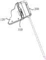
图1是本发明提供的医疗系统的结构示意图;Fig. 1 is the structural representation of medical system provided by the present invention;
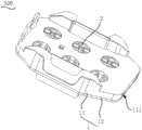
图2是本发明提供的无菌屏障的结构示意图;Fig. 2 is the structural representation of the sterile barrier provided by the present invention;
图3是本发明提供的驱动单元、无菌适配器和手术器械装配后的结构示意图;Fig. 3 is a structural schematic diagram of the assembled drive unit, sterile adapter and surgical instrument provided by the present invention;
图4是本发明提供的驱动单元、无菌适配器和手术器械未装配前的结构示意图;Fig. 4 is a schematic structural view of the drive unit, the sterile adapter and the surgical instrument provided by the present invention before they are assembled;
图5是本发明提供的无菌适配器的结构示意图;Fig. 5 is a schematic structural view of the sterile adapter provided by the present invention;
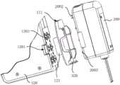
图6是本发明提供的无菌适配器的爆炸图;Figure 6 is an exploded view of the sterile adapter provided by the present invention;
图7是本发明提供的无菌适配器在未装配顶板时的结构示意图;Fig. 7 is a schematic structural view of the aseptic adapter provided by the present invention when the top plate is not assembled;
图8是本发明提供的无菌适配器在制动件将壳体和耦合盘锁定时的剖视图一;Fig. 8 is a sectional view of the aseptic adapter provided by the present invention when the brake part locks the housing and the coupling disc;
图9是本发明提供的无菌适配器在制动件将壳体和耦合盘锁定时的剖视图二;Fig. 9 is the second cross-sectional view of the aseptic adapter provided by the present invention when the brake part locks the housing and the coupling disc;
图10是本发明提供的无菌适配器在制动件将壳体和耦合盘解锁时的剖视图一;Fig. 10 is the first cross-sectional view of the aseptic adapter provided by the present invention when the brake part unlocks the casing and the coupling disc;
图11是本发明提供的无菌适配器在制动件将壳体和耦合盘解锁时的剖视图二;Fig. 11 is the second cross-sectional view of the aseptic adapter provided by the present invention when the brake part unlocks the housing and the coupling disc;
图12是本发明提供的手术器械的主视图;Fig. 12 is the front view of the surgical instrument provided by the present invention;
图13是本发明提供的无菌适配器和手术器械装配后的结构示意图一;Fig. 13 is a structural schematic diagram 1 of the assembled sterile adapter and surgical instrument provided by the present invention;
图14是本发明提供的无菌适配器和手术器械装配后的结构示意图二;Fig. 14 is a structural schematic diagram II of the assembled sterile adapter and surgical instrument provided by the present invention;
图15是本发明提供的无菌适配器和驱动单元未装配时的结构示意图;Fig. 15 is a schematic structural view of the sterile adapter provided by the present invention and the drive unit when they are not assembled;
图16是本发明提供的底板的结构示意图;Fig. 16 is a schematic structural view of the bottom plate provided by the present invention;
图17是本发明提供的无菌适配器和驱动单元装配时的部分结构示意图。Fig. 17 is a partial structural schematic diagram of the assembly of the sterile adapter and the drive unit provided by the present invention.
图中:In the picture:
100、驱动装置;110、机械臂;120、驱动单元;1201、卡孔;1202、第一安装面;1203、第一耦合部;1204、感应件;200、手术器械;2001、第二安装面;2002、卡爪;2003、第二耦合部;2004、第二卡槽;2005、插销;300、无菌屏障;310、无菌盖布;320、无菌适配器;1、壳体;11、顶板;111、第一卡槽;112、卡凸;12、底板;121、卡接臂;1211、卡扣;122、凹陷部;2、耦合盘;21、耦合结构;22、凸起;3、制动件;31、凹槽;32、推动部;33、弹性臂;4、指示销;41、销轴;42、限位凸缘。100. Driving device; 110. Mechanical arm; 120. Driving unit; 1201. Card hole; 1202. First installation surface; 1203. First coupling part; 1204. Inductor; 200. Surgical instrument; ; 2002, claw; 2003, second coupling part; 2004, second slot; 2005, latch; 300, sterile barrier; 310, sterile drape; 320, sterile adapter; Top plate; 111, first slot; 112, protrusion; 12, bottom plate; 121, arm; 1211, buckle; 122, depression; 2, coupling disc; 21, coupling structure; , brake piece; 31, groove; 32, pushing part; 33, elastic arm; 4, indicating pin; 41, pin shaft; 42, limit flange.
具体实施方式Detailed ways
下面结合附图和实施例对本发明作进一步的详细说明。可以理解的是,此处所描述的具体实施例仅仅用于解释本发明,而非对本发明的限定。另外还需要说明的是,为了便于描述,附图中仅示出了与本发明相关的部分而非全部结构。The present invention will be further described in detail below in conjunction with the accompanying drawings and embodiments. It should be understood that the specific embodiments described here are only used to explain the present invention, but not to limit the present invention. In addition, it should be noted that, for the convenience of description, only some structures related to the present invention are shown in the drawings but not all structures.
在本发明的描述中,除非另有明确的规定和限定,术语“相连”、“连接”、“固定”应做广义理解,例如,可以是固定连接,也可以是可拆卸连接,或成一体;可以是机械连接,也可以是电连接;可以是直接相连,也可以通过中间媒介间接相连,可以是两个元件内部的连通或两个元件的相互作用关系。对于本领域的普通技术人员而言,可以具体情况理解上述术语在本发明中的具体含义。In the description of the present invention, unless otherwise clearly specified and limited, the terms "connected", "connected" and "fixed" should be understood in a broad sense, for example, it can be a fixed connection, a detachable connection, or an integrated ; It can be a mechanical connection or an electrical connection; it can be a direct connection or an indirect connection through an intermediary, and it can be the internal communication of two components or the interaction relationship between two components. Those of ordinary skill in the art can understand the specific meanings of the above terms in the present invention in specific situations.
在本发明中,除非另有明确的规定和限定,第一特征在第二特征之“上”或之“下”可以包括第一和第二特征直接接触,也可以包括第一和第二特征不是直接接触而是通过它们之间的另外的特征接触。而且,第一特征在第二特征“之上”、“上方”和“上面”包括第一特征在第二特征正上方和斜上方,或仅仅表示第一特征水平高度高于第二特征。第一特征在第二特征“之下”、“下方”和“下面”包括第一特征在第二特征正下方和斜下方,或仅仅表示第一特征水平高度小于第二特征。In the present invention, unless otherwise clearly specified and limited, a first feature being "on" or "under" a second feature may include direct contact between the first and second features, and may also include the first and second features Not in direct contact but through another characteristic contact between them. Moreover, "above", "above" and "above" the first feature on the second feature include that the first feature is directly above and obliquely above the second feature, or simply means that the first feature is horizontally higher than the second feature. "Below", "beneath" and "under" the first feature to the second feature include that the first feature is directly below and obliquely below the second feature, or simply means that the first feature has a lower level than the second feature.
在本实施例的描述中,术语“上”、“下”、“右”、等方位或位置关系为基于附图所示的方位或位置关系,仅是为了便于描述和简化操作,而不是指示或暗示所指的装置或元件必须具有特定的方位、以特定的方位构造和操作,因此不能理解为对本发明的限制。此外,术语“第一”、“第二”仅仅用于在描述上加以区分,并没有特殊的含义。In the description of this embodiment, the terms "up", "down", "right", and other orientations or positional relationships are based on the orientations or positional relationships shown in the drawings, and are only for the convenience of description and simplification of operations, rather than indicating Or imply that the device or element referred to must have a specific orientation, be constructed and operate in a specific orientation, and therefore should not be construed as limiting the invention. In addition, the terms "first" and "second" are only used to distinguish in description, and have no special meaning.
本实施例提供了一种医疗系统,可以用于外科手术。如图1所示,医疗系统包括驱动装置100、显示装置以及手术器械200。驱动装置100用于驱动手术器械200的末端实现一个或多个自由度,以便手术器械200进行手术操作。显示装置用于显示待手术部位的图像以及各项手术参数,以便医护人员使用该医疗系统。This embodiment provides a medical system that can be used in surgical operations. As shown in FIG. 1 , the medical system includes a
为实现避免手术部位感染,驱动装置100和手术器械200均应为无菌状态,又因驱动装置100中设置有马达、编码器、传感器等电器元件,导致驱动装置100无法采用常规消毒方法(例如蒸汽消毒或加热消毒)。为此,本实施例中的医疗系统还包括无菌屏障300,无菌屏障300罩设于驱动装置100外,从而将驱动装置100与医疗器械隔开,以将非无菌模块和无菌模块隔开,保证与待手术部位接触的模块均为无菌模块,以保证无菌的手术环境。In order to avoid infection of the surgical site, both the
可选地,驱动装置100包括机械臂110以及驱动单元120,驱动单元120设置在机械臂110的末端,通过机械臂110带动驱动单元120转动,驱动单元120的输出端用于驱动手术器械200相对机械臂110移动,以使手术器械200可以灵活地进行手术动作。Optionally, the driving
如图2所示,无菌屏障300包括无菌盖布310以及无菌适配器320,无菌适配器320与无菌盖布310连接,无菌适配器320具有位于无菌盖布310内侧的第一适配表面以及位于无菌盖布310外侧的第二适配表面,第一适配表面用于与驱动装置100装配,第二适配表面与手术器械200装配,以使驱动装置100通过无菌适配器320向手术器械200传动致动扭矩,以驱动手术器械200运动。As shown in Figure 2, the sterile barrier 300 includes a
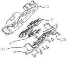
如图3所示,无菌适配器320的相对两侧能够分别与驱动单元120和手术器械200对接,并传动连接驱动单元120和手术器械200,以便在将驱动装置100与手术器械200隔开的基础上,实现正常传动。如图4所示,驱动单元120和手术器械200上均设置有耦合部,为方便介绍,驱动单元120上的耦合部为第一耦合部1203,手术器械200上的耦合部为第二耦合部2003,第一耦合部1203和第二耦合部2003均与无菌适配器320传动配合。As shown in FIG. 3 , the opposite sides of the
如图5所示,无菌适配器320包括壳体1以及耦合盘2。壳体1具有相对设置的第一适配表面和第二适配表面,壳体1上设置有贯穿第一适配表面和第二适配表面的安装孔,耦合盘2转动设置于安装孔内,耦合盘2的沿轴向的两端分别通过安装孔的两端外露于壳体1外,且耦合盘2的沿轴向的两端面上均设置有耦合结构21,耦合结构21能够与对应侧的第一耦合部1203或第二耦合部2003对接,以实现致动扭矩的传递,从而通过驱动单元120驱动手术器械200动作。As shown in FIG. 5 , the
因耦合盘2需要相对壳体1转动,以传递扭矩,这导致无菌适配器320在与驱动单元120安装时耦合盘2的角度不定,需要调整耦合盘2至需要的角度进行接合,增大了装配对接难度。Because the
为解决上述问题,如图6所示,无菌适配器320还包括制动件3,制动件3与壳体1连接,且制动件3能够将耦合盘2和壳体1锁定,阻止耦合盘2相对壳体1转动,以使耦合盘2在无菌适配器320未与驱动单元120装配时始终处于初始角度,方便耦合盘2与驱动单元120对接。在无菌适配器320的壳体1安装于驱动装置100时,制动件3能够在驱动装置100作用下解除耦合盘2和壳体1的锁定状态,以便无菌适配器320与驱动装置100安装后,耦合盘2能够相对壳体1转动,从而传递致动扭矩。In order to solve the above problems, as shown in Figure 6, the
为方便制动件3与壳体1的装配,壳体1包括可拆装连接的顶板11和底板12,制动件3设置在顶板11和底板12之间。具体地,顶板11和底板12通过螺钉连接,以使拆装方便。顶板11上设置有第一安装孔,底板12上在于第一安装孔对应的位置设置有第二安装孔,第一安装孔与正对的第二安装孔组成安装耦合盘2的安装孔。In order to facilitate the assembly of the
具体地,如图7所示,制动件3设置于顶板11和底板12之间,且能够在锁定位置和解锁位置间切换。耦合盘2的外周面上沿其径向凸设有凸起22,制动件3上设置有与凸起22配合的凹槽31。无菌适配器320未与驱动单元120装配时,制动件3位于锁定位置,此时,凸起22位于凹槽31内,以阻止耦合盘2转动,从而使壳体1与耦合盘2锁定。当无菌适配器320安装于驱动单元120上时,驱动单元120将驱动制动件3由锁定位置移动至解锁位置,以使凸起22与凹槽31脱离,从而解除耦合盘2与壳体1的锁定,使耦合盘2能够相对壳体1转动。Specifically, as shown in FIG. 7 , the braking
一些实施例中,耦合盘2的外周面上设置有凹槽31,制动件3上设置有与凹槽31配合的凸起22,同样可以锁定耦合盘2和壳体1。In some embodiments, a
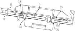
可选地,无菌适配器320包括多个耦合盘2,制动件3能与多个耦合盘2配合,以同时将多个耦合盘2与壳体1锁定或解锁。具体地,多个耦合盘2呈至少两排设置,每相邻的两排耦合盘2之间设置有一制动件3,制动件3分别与相邻的两排耦合盘2配合。通过将耦合盘2采用上述排布方式,可以使用一个制动件3配合多个耦合盘2,减少制动件3的数量,使无菌适配器320的结构更简单,有利于降低无菌适配器320的成本。Optionally, the
本实施例中,耦合盘2的数量为六个,六个耦合盘2呈两排设置,制动件3为长条形,且设置在两排耦合盘2之间,制动件3上对应每个耦合盘2均设置有凹槽31。In this embodiment, the number of
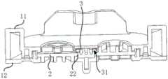
为使制动件3能够在壳体1内活动,顶板11和底板12之间形成有容纳制动件3的安装腔,如图8所示,制动件3上构造有推动部32。当无菌适配器320与驱动单元120装配时,驱动单元120能够与推动部32抵接,并推动推动部32相壳体1内移动带动制动件3相对壳体1移动,进而使凸起22与凹槽31脱离。In order to enable the
可以理解的是,为了确保制动件3能够在壳体1内移动,安装腔沿推动部32的推动方向的尺寸大于制动件3沿推动部32的推动方向的尺寸,以使安装腔内预留有制动件3的活动空间。It can be understood that, in order to ensure that the
可选地,顶板11的底面和/或底板12的顶面设置有突出部,突出部能够与底板12或顶板11抵接,以使顶板11和底板12隔开以形成安装腔。其中,突出部可以为凸柱或筋板。Optionally, a protrusion is provided on the bottom surface of the
本实施例中,凹槽31为沿顶板11和底板12的排列方向延伸的通槽,如图8所示,制动件3靠近底板12的一侧向背离顶板11的方向延伸有推动部32。当无菌适配器320未与驱动单元120安装时,如图9所示,凸起22位于凹槽31内,推动部32能伸出壳体1外。当无菌适配器320与驱动单元120装配过程中,如图10所示,驱动单元120的表面(与第一适配面配合的表面)与推动部32抵接,并通过推动部32推动制动件3向靠近顶板11的方向移动,当制动件3与顶板11抵接时,如图11所示凸起22与凹槽31完全脱离。In this embodiment, the
为使制动件3更易由锁定位置切换至解锁位置,制动件3上设置有避让孔,避让孔紧邻推动部32设置。当推动部32受力时,制动件3更易移动,且制动件3更易在推动部32的作用下变形,以进一步保证凸起22能够与凹槽31脱离。In order to make it easier for the
进一步地,制动件3上构造有弹性臂33,弹性臂33位于避让孔内,弹性臂33的固定段与避让孔的内壁连接,弹性臂33的自由端始终与顶板11的底面内壁抵接。在无菌适配器320安装于驱动单元120时,推动部32推动制动件3向顶板11方向移动时,弹性臂33的自由端与顶板11之间的抵接力增大,使得弹性臂33的固定端能够对制动片施加朝向顶板11方向的弹力,以便进一步保证制动件3能够移动至解锁位置处。Further, the braking
可选地,弹性臂33包括呈夹角设置的第一连接臂和第二连接臂。在无菌适配器320未与驱动单元120装配时,第一连接臂大致与顶板11平行,第二连接臂大致沿顶板11和底板12的排列方向延伸,且第二连接臂的一端与顶板11抵接。当无菌适配器320与驱动单元120装配时,驱动单元120推动推动部32靠近顶板11,此过程中第二连接臂与顶板11之间的抵接力增大,导致第一连接臂将发生变形至图10所示状态,第一连接臂的远离第二连接臂的一端将带动制动件3靠近顶板11,以使凸起22与凹槽31完全脱离。Optionally, the
进一步地,第二连接臂的两端分别与顶板11和底板12抵接,以使第一连接臂能够顺利变形以带动制动板向靠近顶板11的方向移动。Furthermore, both ends of the second connecting arm abut against the
可选地,弹性臂33与制动件3为一体成型结构,以提高第一连接臂与制动件3的联动效果。Optionally, the
如图12所示,手术器械200具有与第二适配表面配合的第二安装面2001,第二安装面2001上设置有与耦合盘2配合的第二耦合部2003,耦合盘2能够带动第二耦合部2003同步转动。为方便耦合盘2与第二耦合部2003顺利配合,且方便用户人员了解耦合盘2的当前旋转角度,耦合结构21为非回转结构,以便阻止耦合结构21与第二耦合部2003发生相对转动。进一步地,耦合结构21的至少相对两侧的外轮廓形状不同,以形成防呆结构,第二耦合部2003的形状及大小与耦合结构21相适配。通过形成防呆结构,一方面便于耦合盘2与第二耦合部2003对接,另一方面能够方便医护人员区分耦合结构21的旋转角度。As shown in FIG. 12 , the
本实施例中,耦合结构21为凹陷结构,对应地,第二耦合部2003为凸出结构,以实现耦合盘2与手术器械200的耦接配合。In this embodiment, the
一些实施例中,耦合结构21可以为凸出结构或凹陷和凸起22的组合结构,对应地,第二耦合部2003为凹陷结构,或凸起22和凹陷的组合结构,均可以实现耦合盘2与手术器械200的耦接配合。In some embodiments, the
为避免耦合盘2与第二耦合部2003脱离,壳体1与手术器械200可拆装连接,以提高装配的稳定性。本实施例中,壳体1与手术器械200卡接,以方便拆装。In order to prevent the
如图13所示,壳体1上设置有卡槽,手术器械200的第二安装面2001上设置有卡爪2002,卡爪2002能与第一卡槽111卡接配合。如图14所示,壳体1的与第一卡槽111相对的一侧设置有卡凸112,手术器械200上与卡凸112对应位置设置有第二卡槽2004,卡凸112能与第二卡槽2004卡接配合。无菌适配器320和手术器械200通过在相对的两侧均通过卡接结构连接,能够提高无菌适配器320和手术器械200的固定效果,使二者固定更牢固。As shown in FIG. 13 , the casing 1 is provided with a locking slot, and the
一些实施例中,卡爪2002可以设置在壳体1上,对应地,第一卡槽111设置于手术器械200上;卡凸112可以设置在手术器械200上,对应地,第二卡槽2004设置在无菌适配器320上,同样可以实现无菌适配器320与手术器械200的可拆装连接。In some embodiments, the
如图17所示,驱动单元120上设置有与第一适配表面配合的第一安装面1202,第一安装面1202上设置有与耦合盘2配合的第一耦合部1203,第一耦合部1203能够带动耦合盘2同步转动。本实施例中,耦合盘2的与第一耦合部1203配合的耦合结构21同样为非回转结构,耦合结构21的至少相对两侧的外轮廓形状不同,以形成防呆结构。第一耦合部1203的形状及大小与该耦合结构21相适配,以便于耦合盘2与第一耦合部1203对接,方便医护人员区分耦合结构21的旋转角度。As shown in FIG. 17 , the
耦合盘2与第一耦合部1203的配合结构可以与耦合盘2与第二耦合部2003的配合结构相同,此处不再具体赘述。The matching structure of the
为避免耦合盘2与第一耦合部1203脱离,无菌适配器320与驱动单元120可拆装连接,以提高装配的稳定性。本实施例中,壳体1与驱动单元120卡接,以方便拆装。In order to prevent the
如图15所示,底板12上构造有卡接臂121,卡接臂121沿顶板11和底板12的排列方向延伸,卡接臂121的一端(以下称为顶端)由底板12的顶面向上延伸并穿过顶板11,卡接臂121的另一端(以下称为底端)由底板12的底面向下延伸并能与驱动装置100卡接。当无菌适配器320与驱动单元120装配时,扳动卡接臂121的顶端,能够带动卡接臂121的底端移动,以便于与驱动单元120卡接。具体地,卡接臂121的底端设置有卡扣1211,驱动单元120上设置有卡孔1201,卡扣1211能够与卡孔1201卡接,以将驱动单元120与无菌适配器320固定。As shown in FIG. 15 , the
为提高驱动单元120与无菌适配器320的卡接稳定性,底板12上设置有至少一组卡接臂121,每组卡接臂121包括相对设置有两个卡接臂121,每个卡接臂121朝向同组另一卡接臂121的方向构造有卡扣1211,驱动单元120被卡接固定在同组的两个卡接臂121之间,以使卡接效果更牢固。装配驱动单元120与无菌适配器320时,按压同组的两个卡接臂121的顶端,使同组的两个卡接臂121的顶端相互靠近,能够带动同组两个卡接臂121的底端相互背离,以增大同组两个卡扣1211之间的距离,从而方便无菌适配器320与驱动单元120卡接。In order to improve the clamping stability of the
为使卡接臂121更易变形,如图16所示,底板12的与卡接臂121连接位置处构造为柔性结构,以使卡接臂121的顶端受到外力时,卡接臂121更易相对底板12转动,以使卡接臂121的底端移动。In order to make the
本实施例中,底板12的与卡接臂121连接位置处设置有凹陷部122,以形成柔性结构。可选地,凹陷部122可以为凹槽31。凹槽31可以为长条形,并围绕卡接臂121的周向延伸。凹槽31数量可以为一个,凹槽31也可以间断设置多段。In this embodiment, a recessed
可选地,凹陷部122为凹坑,凹坑设置有多个,并沿卡接臂121的周向排列。Optionally, the recessed
一些实施例中,柔性结构也可以为薄壁结构,同样可以使卡接臂121更易相对底板12转动。In some embodiments, the flexible structure can also be a thin-walled structure, which can also make it easier for the
如图17所示,无菌适配器320还包括指示销4,指示销4与壳体1活动连接,指示销4能在手术器械200的推动下触发驱动装置100上的感应件1204,以便医疗系统获取无菌适配器320与手术器械200的装配情况。As shown in Figure 17, the
具体地,壳体1上设置有滑动通孔,指示销4滑动设置于滑动通孔内,指示销4的一端能与手术器械200抵接,指示销4的另一端能触发感应件1204。当无菌适配器320与手术器械200装配后,手术器械200将推动指示销4在滑动通孔内滑动,以使指示销4移动并触发感应件1204。Specifically, the casing 1 is provided with a sliding through hole, and the indicating
本实施例中,滑动通孔贯穿顶板11和底板12,指示销4设置在滑动通孔内,并能沿顶板11和底板12的排列方向滑动。当无菌适配器320与手术器械200装配后,手术器械200推动指示销4向靠近底板12的方向移动,以触发感应件1204。当感应件1204被触发后,感应件1204将向医疗系统的控制装置发送信号,控制装置根据接收到的信号,获取手术器械200已与无菌适配器320装配。In this embodiment, the sliding through hole runs through the
可选地,感应件1204可以为微动开关或接近开关。当感应件1204为微动开关时,指示销4向靠近底板12的方向移动时能按压微动开关,以触发微动开关。当感应件1204为接近开关时,指示销4与接近开关的距离小于指定距离后,可以触发接近开关。Optionally, the
为避免指示销4与壳体1脱离,指示销4包括销轴41以及沿销轴41的径向凸设的限位凸缘42,滑动通孔包括依次连通的第一孔径段、第二孔径段和第三孔径段,第一孔径段和第二孔径段的孔径均小于第二孔径段的孔径,且第一孔径段和第二孔径段的孔径均大于销轴41的直径并小于限位凸缘42的直径,限位凸缘42的直径小于第二孔径段的直径,限位凸缘42位于第二孔径段内,第二孔径段的轴向尺寸大于限位凸缘42的轴向尺寸。限位凸缘42限位于第二孔径段,能够避免指示销4与壳体1脱离,还能够限制指示销4的极限位置,避免指示销4过度移动而损坏感应件1204。In order to prevent the
为方便指示销4与壳体1装配,第一孔径段和第二孔径段设置于底板12上,第三孔径段设置于顶板11上。To facilitate the assembly of the indicating
可选地,指示销4可以通过弹性件与壳体1弹性连接。弹性件能驱动指示销4向靠近顶板11的方向移动,以便在无菌适配器320与手术器械200脱离后,能够自动复位,不再触发感应件1204,从而使医疗系统的控制装置能够根据感应件1204的信号变化及时得知手术器械200未与无菌适配器320装配。Optionally, the
可选地,手术器械200上设置有插销2005,插销2005能够推动指示销4,以使指示销4触发感应件1204。Optionally, the
一些实施例中,无菌适配器320可以不设置指示销4,通过延长插销2005的长度,通过插销2005传动壳体1后触发感应件1204。In some embodiments, the
显然,本发明的上述实施例仅仅是为了清楚说明本发明所作的举例,而并非是对本发明的实施方式的限定。对于所属领域的普通技术人员来说,能够进行各种明显的变化、重新调整和替代而不会脱离本发明的保护范围。这里无需也无法对所有的实施方式予以穷举。凡在本发明的精神和原则之内所作的任何修改、等同替换和改进等,均应包含在本发明权利要求的保护范围之内。Apparently, the above-mentioned embodiments of the present invention are only examples for clearly illustrating the present invention, rather than limiting the implementation of the present invention. Various obvious changes, readjustments, and substitutions will occur to those skilled in the art without departing from the scope of the present invention. It is not necessary and impossible to exhaustively list all the implementation manners here. All modifications, equivalent replacements and improvements made within the spirit and principles of the present invention shall be included within the protection scope of the claims of the present invention.
Claims (11)
Priority Applications (2)
| Application Number | Priority Date | Filing Date | Title |
|---|---|---|---|
| CN202111226052.7ACN115998438A (en) | 2021-10-21 | 2021-10-21 | Sterile adapter, sterile barrier and medical system |
| PCT/CN2022/126300WO2023066321A1 (en) | 2021-10-21 | 2022-10-20 | Sterile adapter, sterile barrier, and medical system |
Applications Claiming Priority (1)
| Application Number | Priority Date | Filing Date | Title |
|---|---|---|---|
| CN202111226052.7ACN115998438A (en) | 2021-10-21 | 2021-10-21 | Sterile adapter, sterile barrier and medical system |
Publications (1)
| Publication Number | Publication Date |
|---|---|
| CN115998438Atrue CN115998438A (en) | 2023-04-25 |
Family
ID=86030362
Family Applications (1)
| Application Number | Title | Priority Date | Filing Date |
|---|---|---|---|
| CN202111226052.7APendingCN115998438A (en) | 2021-10-21 | 2021-10-21 | Sterile adapter, sterile barrier and medical system |
Country Status (2)
| Country | Link |
|---|---|
| CN (1) | CN115998438A (en) |
| WO (1) | WO2023066321A1 (en) |
Cited By (2)
| Publication number | Priority date | Publication date | Assignee | Title |
|---|---|---|---|---|
| CN116551742A (en)* | 2023-07-10 | 2023-08-08 | 科弛医疗科技(北京)有限公司 | Surgical robot and method for initializing zero position of transmission shaft of instrument box |
| CN119174650A (en)* | 2023-06-21 | 2024-12-24 | 武汉联影智融医疗科技有限公司 | Instrument box, surgical instrument and surgical robot |
Citations (2)
| Publication number | Priority date | Publication date | Assignee | Title |
|---|---|---|---|---|
| CN102014759A (en)* | 2008-06-11 | 2011-04-13 | 韩商未来股份有限公司 | Instrument of surgical robot arm |
| CN110448383A (en)* | 2014-03-17 | 2019-11-15 | 直观外科手术操作公司 | Latch of the surgical operating instrument fixed to actuator will be remotely operated |
Family Cites Families (3)
| Publication number | Priority date | Publication date | Assignee | Title |
|---|---|---|---|---|
| US7331967B2 (en)* | 2002-09-09 | 2008-02-19 | Hansen Medical, Inc. | Surgical instrument coupling mechanism |
| CN108066015B (en)* | 2016-11-14 | 2023-01-10 | 惠州科赛医疗有限公司 | Pump body clamping device |
| BR112019010623B1 (en)* | 2016-12-20 | 2023-01-24 | Verb Surgical Inc | SYSTEM FOR USE IN A ROBOTIC SURGICAL SYSTEM AND METHOD OF OPERATING A ROBOTIC SURGICAL SYSTEM |
- 2021
- 2021-10-21CNCN202111226052.7Apatent/CN115998438A/enactivePending
- 2022
- 2022-10-20WOPCT/CN2022/126300patent/WO2023066321A1/ennot_activeCeased
Patent Citations (2)
| Publication number | Priority date | Publication date | Assignee | Title |
|---|---|---|---|---|
| CN102014759A (en)* | 2008-06-11 | 2011-04-13 | 韩商未来股份有限公司 | Instrument of surgical robot arm |
| CN110448383A (en)* | 2014-03-17 | 2019-11-15 | 直观外科手术操作公司 | Latch of the surgical operating instrument fixed to actuator will be remotely operated |
Cited By (3)
| Publication number | Priority date | Publication date | Assignee | Title |
|---|---|---|---|---|
| CN119174650A (en)* | 2023-06-21 | 2024-12-24 | 武汉联影智融医疗科技有限公司 | Instrument box, surgical instrument and surgical robot |
| CN116551742A (en)* | 2023-07-10 | 2023-08-08 | 科弛医疗科技(北京)有限公司 | Surgical robot and method for initializing zero position of transmission shaft of instrument box |
| CN116551742B (en)* | 2023-07-10 | 2023-11-17 | 科弛医疗科技(北京)有限公司 | Surgical robot and method for initializing zero position of transmission shaft of instrument box |
Also Published As
| Publication number | Publication date |
|---|---|
| WO2023066321A1 (en) | 2023-04-27 |
Similar Documents
| Publication | Publication Date | Title |
|---|---|---|
| WO2023066321A1 (en) | Sterile adapter, sterile barrier, and medical system | |
| CN111565667B (en) | Sterile interface module for robotic surgical assembly | |
| US12426963B2 (en) | Transmission, driving, and sterile assemblies, surgical instrument and system, and surgical robot | |
| CN111050684B (en) | Sterile adapter for a linear actuation instrument driver | |
| KR102274815B1 (en) | Sterile adapters for use in robotic surgical systems | |
| CN112472160B (en) | Surgical instruments and surgical robots | |
| CN107595394B (en) | Surgical instrument quick-change mechanism | |
| CN219109732U (en) | Sterile adapter | |
| CN219461396U (en) | Surgical instrument device and surgical robot | |
| CN112472010B (en) | Endoscope, image processing device and surgical robot | |
| JP6819966B2 (en) | Adapters or adapter systems for functionally sterilizing medical devices | |
| CN211460507U (en) | Minimally invasive surgery robot | |
| CN114052919A (en) | Power connecting device, tail end execution equipment and laparoscopic robot | |
| CN214434482U (en) | Quick plug devices, actuators and surgical robots | |
| JP2019092533A (en) | Adaptor and medical manipulator system | |
| CN211834695U (en) | Minimally invasive surgery robot | |
| CN219289686U (en) | A sterile plate connection structure for a surgical robot | |
| WO2024109626A1 (en) | Sterile adapter | |
| CN215349142U (en) | Surgical instrument and surgical robot | |
| CN116584986A (en) | Method of engaging a medical instrument cassette with an instrument manipulator | |
| CN116551668A (en) | Sterile Units and Manipulators for Robotic Surgery | |
| CN222676429U (en) | Surgical robot and sterile barrier system thereof | |
| CN116115276A (en) | Sterile adapter, sterile barrier and medical system | |
| CN221060841U (en) | Isolation fastener, isolation structure and surgical robot | |
| KR102635808B1 (en) | Module detachable structure for medical equipment |
Legal Events
| Date | Code | Title | Description |
|---|---|---|---|
| PB01 | Publication | ||
| PB01 | Publication | ||
| SE01 | Entry into force of request for substantive examination | ||
| SE01 | Entry into force of request for substantive examination |