CN115995985A - A Control Method of Bidirectional Symmetrical LLC Resonant Converter - Google Patents
A Control Method of Bidirectional Symmetrical LLC Resonant ConverterDownload PDFInfo
- Publication number
- CN115995985A CN115995985ACN202310110256.7ACN202310110256ACN115995985ACN 115995985 ACN115995985 ACN 115995985ACN 202310110256 ACN202310110256 ACN 202310110256ACN 115995985 ACN115995985 ACN 115995985A
- Authority
- CN
- China
- Prior art keywords
- llc resonant
- resonant converter
- mode
- symmetrical
- voltage
- Prior art date
- Legal status (The legal status is an assumption and is not a legal conclusion. Google has not performed a legal analysis and makes no representation as to the accuracy of the status listed.)
- Granted
Links
Images


Classifications
- Y—GENERAL TAGGING OF NEW TECHNOLOGICAL DEVELOPMENTS; GENERAL TAGGING OF CROSS-SECTIONAL TECHNOLOGIES SPANNING OVER SEVERAL SECTIONS OF THE IPC; TECHNICAL SUBJECTS COVERED BY FORMER USPC CROSS-REFERENCE ART COLLECTIONS [XRACs] AND DIGESTS
- Y02—TECHNOLOGIES OR APPLICATIONS FOR MITIGATION OR ADAPTATION AGAINST CLIMATE CHANGE
- Y02B—CLIMATE CHANGE MITIGATION TECHNOLOGIES RELATED TO BUILDINGS, e.g. HOUSING, HOUSE APPLIANCES OR RELATED END-USER APPLICATIONS
- Y02B70/00—Technologies for an efficient end-user side electric power management and consumption
- Y02B70/10—Technologies improving the efficiency by using switched-mode power supplies [SMPS], i.e. efficient power electronics conversion e.g. power factor correction or reduction of losses in power supplies or efficient standby modes
Landscapes
- Dc-Dc Converters (AREA)
Abstract
Translated fromChinese
Description
Translated fromChinese技术领域Technical Field
本发明涉及电子电路领域,具体涉及一种双向对称LLC谐振变换器的控制方法。The invention relates to the field of electronic circuits, and in particular to a control method for a bidirectional symmetrical LLC resonant converter.
背景技术Background Art
随着科技发展日新月异,人们对生活物质条件的要求也逐渐增高,对户用储能,便携式储能及车载储蓄电源的可靠性、舒适性、节能清洁等方面的要求进一步提高。随着储能技术的不断发展,实现储能系统与直流电网能量交互的双向DC/DC变换器得到了广泛研究,人们对电源的效率、功率密度、噪声等指标均提出了更高的要求,对输入电压范围和负载调制范围的要求越来越宽,对输出功率的控制越来越严格。双向对称谐振变换器由于具有高开关频率、宽增益范围,正反向工作特性一致等优点近年来受到了广泛关注。With the rapid development of science and technology, people's requirements for living material conditions are gradually increasing, and the requirements for the reliability, comfort, energy saving and cleanliness of household energy storage, portable energy storage and vehicle-mounted energy storage power supply are further improved. With the continuous development of energy storage technology, bidirectional DC/DC converters that realize energy interaction between energy storage systems and DC power grids have been widely studied. People have put forward higher requirements for power efficiency, power density, noise and other indicators, and the requirements for input voltage range and load modulation range are getting wider and wider, and the control of output power is becoming more and more stringent. Bidirectional symmetrical resonant converters have received widespread attention in recent years due to their advantages such as high switching frequency, wide gain range, and consistent forward and reverse working characteristics.
现有的双向对称谐振变换器的控制方法主要是变频控制,在谐振腔参数已经确定的情况下,系统的增益特性就已经固定,在电压增益大于1时,变频控制可以得到较大的电压增益,在电压增益小于1时,输入电压范围和负载范围都增大时,开关频率的调节范围也要随之增大,此时的变频控制对增益的调节非常有限,且此时的变换器副边侧丢失零电流关断能力,输出电压纹波和电源效率也难以满足要求。The existing control method of bidirectional symmetrical resonant converter is mainly frequency conversion control. When the parameters of the resonant cavity have been determined, the gain characteristics of the system are fixed. When the voltage gain is greater than 1, the frequency conversion control can obtain a larger voltage gain. When the voltage gain is less than 1, when the input voltage range and the load range increase, the adjustment range of the switching frequency should also increase accordingly. At this time, the frequency conversion control has very limited adjustment on the gain, and the secondary side of the converter loses the zero current shutdown capability, and the output voltage ripple and power efficiency are difficult to meet the requirements.
发明内容Summary of the invention
本发明提供一种双向对称LLC谐振变换器的控制方法,既可以实现宽输入范围和宽负载范围下的稳定工作,又可以实现功率调制功能。The present invention provides a control method for a bidirectional symmetrical LLC resonant converter, which can realize stable operation under a wide input range and a wide load range, and can also realize a power modulation function.
本发明通过下述技术方案实现:The present invention is achieved through the following technical solutions:
一种双向对称LLC谐振变换器的控制方法,包括以下步骤:A control method for a bidirectional symmetrical LLC resonant converter comprises the following steps:
S1、判断双向对称LLC谐振变换器的工作模式为电压增益模式或功率调制模式,若所述工作模式为功率调制模式,则所述双向对称LLC谐振变换器的调制方式为固定频率的准多相移调制方式,否则,跳转至S2;S1, judging whether the working mode of the bidirectional symmetrical LLC resonant converter is a voltage gain mode or a power modulation mode, if the working mode is a power modulation mode, the modulation mode of the bidirectional symmetrical LLC resonant converter is a fixed frequency quasi-multi-phase shift modulation mode, otherwise, jumping to S2;
S2、判断所述双向对称LLC谐振变换器的工作状态为高增益工作状态或低增益工作状态,若所述工作状态为高增益工作状态,则所述双向对称LLC谐振变换器的调制方式为变频控制方式,否则,所述双向对称LLC谐振变换器的调制方式为固定频率的准多相移调制方式。S2. Determine whether the working state of the bidirectional symmetrical LLC resonant converter is a high-gain working state or a low-gain working state. If the working state is a high-gain working state, the modulation mode of the bidirectional symmetrical LLC resonant converter is a variable frequency control mode. Otherwise, the modulation mode of the bidirectional symmetrical LLC resonant converter is a fixed-frequency quasi-multi-phase shift modulation mode.
作为优化,S1中,判断所述双向对称LLC谐振变换器的工作模式的依据为由用户根据实际需求设定。As an optimization, in S1, the basis for determining the working mode of the bidirectional symmetrical LLC resonant converter is set by the user according to actual needs.
作为优化,S2的判断依据为:输入电压、输出电压和输出电流的采样值。As an optimization, the judgment basis of S2 is: the sampling values of input voltage, output voltage and output current.
作为优化,S2中,在对所述双向对称LLC谐振变换器进行工作模式判断之前,还需判断所述双向对称LLC谐振变换器为正向工作状态或反向工作状态。As an optimization, in S2, before determining the working mode of the bidirectional symmetrical LLC resonant converter, it is also necessary to determine whether the bidirectional symmetrical LLC resonant converter is in a forward working state or a reverse working state.
作为优化,所述双向对称LLC谐振变换器在功率调制模式下,通过调节所述双向对称LLC谐振变换器的原边侧与副边侧的桥间相移角θ的大小控制输出。As an optimization, in the power modulation mode, the bidirectional symmetrical LLC resonant converter controls the output by adjusting the magnitude of the inter-bridge phase shift angle θ between the primary side and the secondary side of the bidirectional symmetrical LLC resonant converter.
作为优化,所述双向对称LLC谐振变换器在电压增益模式的低增益工作状态下,通过调节所述双向对称LLC谐振变换器的桥臂内相移φp控制输出。As an optimization, the bidirectional symmetrical LLC resonant converter controls the output by adjusting the phase shift φp within the bridge arm of the bidirectional symmetrical LLC resonant converter in the low-gain working state of the voltage gain mode.
作为优化,所述双向对称LLC谐振变换器在电压增益模式的高增益工作状态下,通过调节所述双向对称LLC谐振变换器的开关频率控制输出。As an optimization, the bidirectional symmetrical LLC resonant converter controls the output by adjusting the switching frequency of the bidirectional symmetrical LLC resonant converter in a high-gain working state of a voltage gain mode.
作为优化,所述正向工作状态为:所述双向对称LLC谐振变换器的输入在原边侧,输出在副边侧;所述反向工作状态为:所述双向对称LLC谐振变换器的输入在副边侧,输出在原边侧。As an optimization, the forward working state is: the input of the bidirectional symmetrical LLC resonant converter is on the primary side, and the output is on the secondary side; the reverse working state is: the input of the bidirectional symmetrical LLC resonant converter is on the secondary side, and the output is on the primary side.
作为优化,所述双向对称LLC谐振变换的电路成对称结构,两端分别为高压和低压直流母线,两条直流母线分别对接两个全桥,每个全桥由两组串联的两个开关管并联而成,每组串联开关管中点引出导线连接谐振腔;谐振腔为一个二端口网络,一个端口连接高压侧两桥臂中点,另一个端口连接低压侧两桥臂中点;谐振腔中间为一个变压器,所述变压器的高压侧串联有高压侧电感Lr和高压侧电容Cr,最终串接在高压侧端口上,且所述高压侧端口未设置所述高压侧电感Lr和高压侧电容Cr的一端连接有第一电感Lm和第二电感Lc的其中一端,所述第一电感Lm和第二电感Lc的另一端分别连接在所述高压侧电感Lr和高压侧电容Cr相互远离的一端。As an optimization, the circuit of the bidirectional symmetrical LLC resonant conversion is a symmetrical structure, with high-voltage and low-voltage DC busbars at both ends respectively, and the two DC busbars are connected to two full bridges respectively, each full bridge is composed of two groups of two switch tubes connected in parallel in series, and a wire is led out from the midpoint of each group of series switch tubes to connect the resonant cavity; the resonant cavity is a two-port network, one port is connected to the midpoint of the two bridge arms on the high-voltage side, and the other port is connected to the midpoint of the two bridge arms on the low-voltage side; there is a transformer in the middle of the resonant cavity, and the high-voltage side of the transformer is connected in series with a high-voltage side inductor Lr and a high-voltage side capacitorCr , which are finally connected in series to the high-voltage side port, and one end of the high-voltage side port where the high-voltage side inductor Lr and the high-voltage side capacitorCr are not provided is connected to one end of the first inductor Lm and the second inductor Lc , and the other ends of the first inductor Lm and the second inductor Lc are respectively connected to ends of the high-voltage side inductor Lr and the high-voltage side capacitorCr that are far away from each other.
作为优化,所述变压器的变比为n,对应参数关系为:
本发明与现有技术相比,具有如下的优点和有益效果:Compared with the prior art, the present invention has the following advantages and beneficial effects:
本发明针对双向对称LLC谐振变换器,提出来一种将变频控制方式与固定频率的准多相移控制方式结合起来的混合控制策略,在变换器增益大于1时,采用变频控制方式,工作在大于1的增益范围内时变频控制可以实现原边侧开关管的零电压开通和副边侧开关管的零电流关断从而降低开关损耗,提高变换器工作效率,且此范围内变频控制的输出电压稳定,输出纹波小;在变换器增益小于1时,采用固定频率的准多相移控制方式,可以稳定实现增益小于1的增益调制,调节范围大并同时具有与负载无关的增益特性;此外,根据所需功能还可以实现功率调制,且上述的控制方式在每种工作状态下均只有一个控制变量,便于变量的控制。The present invention is directed to a bidirectional symmetrical LLC resonant converter and proposes a hybrid control strategy that combines a variable frequency control method with a fixed frequency quasi-multiphase shift control method. When the converter gain is greater than 1, a variable frequency control method is adopted. When working in a gain range greater than 1, the variable frequency control can achieve zero voltage turn-on of the primary side switch tube and zero current turn-off of the secondary side switch tube, thereby reducing switching losses and improving the working efficiency of the converter. In this range, the output voltage of the variable frequency control is stable and the output ripple is small. When the converter gain is less than 1, a fixed frequency quasi-multiphase shift control method is adopted, which can stably achieve gain modulation with a gain less than 1, with a large adjustment range and a gain characteristic that is independent of the load. In addition, power modulation can also be achieved according to the required function, and the above-mentioned control method has only one control variable in each working state, which is convenient for variable control.
附图说明BRIEF DESCRIPTION OF THE DRAWINGS
为了更清楚地说明本发明示例性实施方式的技术方案,下面将对实施例中所需要使用的附图作简单地介绍,应当理解,以下附图仅示出了本发明的某些实施例,因此不应被看作是对范围的限定,对于本领域普通技术人员来讲,在不付出创造性劳动的前提下,还可以根据这些附图获得其他相关的附图。在附图中:In order to more clearly illustrate the technical solutions of the exemplary embodiments of the present invention, the following briefly introduces the drawings required for use in the embodiments. It should be understood that the following drawings only illustrate certain embodiments of the present invention and should not be regarded as limiting the scope. For ordinary technicians in this field, other relevant drawings can be obtained based on these drawings without creative work. In the drawings:
图1为本发明所述的一种双向对称LLC谐振变换器的拓扑图;FIG1 is a topological diagram of a bidirectional symmetrical LLC resonant converter according to the present invention;
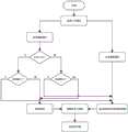
图2为本发明实施例的一种双向对称LLC谐振变换器的控制方法的流程图;FIG2 is a flow chart of a control method of a bidirectional symmetrical LLC resonant converter according to an embodiment of the present invention;
图3为本发明实施例在固定频率下准多相移控制方式的开关管驱动波形图。FIG3 is a waveform diagram of switch tube driving in a quasi-multi-phase shift control mode at a fixed frequency according to an embodiment of the present invention.
具体实施方式DETAILED DESCRIPTION
为使本发明的目的、技术方案和优点更加清楚明白,下面结合实施例和附图,对本发明作进一步的详细说明,本发明的示意性实施方式及其说明仅用于解释本发明,并不作为对本发明的限定。In order to make the objectives, technical solutions and advantages of the present invention more clearly understood, the present invention is further described in detail below in conjunction with embodiments and drawings. The exemplary implementation modes of the present invention and their description are only used to explain the present invention and are not intended to limit the present invention.
实施例Example
本发明实施例中一种双向对称LLC环路下的控制方法根据实时的输入电压、输出电流和电压采样结果划分电源的工作模式和工作状态,然后根据工作状态选择相对应的控制方式。选择对应的控制方式后,通过系统自身的环路控制方式(PI,2P2Z或是其他高阶的负反馈控制方式)改变实时驱动信号的频率和三种相角来调节系统的增益大小和功率,在对驱动信号的频率和相角进行操作时,应按照固定的步径对驱动信号的频率和相角进行缓慢、平滑的变化,以达到稳定过渡的效果,使得全电压范围、全负载范围内均能稳定工作,既可以实现宽输入范围和宽负载范围下的稳定工作,又可以实现功率调制功能,具体包括如下步骤:In an embodiment of the present invention, a control method under a bidirectional symmetrical LLC loop divides the working mode and working state of the power supply according to the real-time input voltage, output current and voltage sampling results, and then selects the corresponding control method according to the working state. After selecting the corresponding control method, the frequency and three phase angles of the real-time drive signal are changed through the system's own loop control method (PI, 2P2Z or other high-order negative feedback control methods) to adjust the gain and power of the system. When operating the frequency and phase angle of the drive signal, the frequency and phase angle of the drive signal should be changed slowly and smoothly according to a fixed step path to achieve a stable transition effect, so that it can work stably in the full voltage range and full load range, and can achieve stable operation under a wide input range and a wide load range, and can also achieve power modulation function, which specifically includes the following steps:
首先,由用户输入选择工作模式,即电压增益模式和功率调制模式,开启采样模块,根据实时的输入电压、输出电流和电压采样结果确定变换器的工作状态,判断直流变换器的工作状态是正向工作状态还是反向工作状态;正向工作状态指的是从原边侧输入,副边侧输出;反向工作状态指的是副边侧输入,原边侧输出;First, the user inputs the selection of the working mode, i.e., the voltage gain mode and the power modulation mode, and starts the sampling module. The working state of the converter is determined according to the real-time input voltage, output current, and voltage sampling results, and it is determined whether the working state of the DC converter is a forward working state or a reverse working state; the forward working state refers to input from the primary side and output from the secondary side; the reverse working state refers to input from the secondary side and output from the primary side;
再者,当双向对称LLC谐振变换器工作在电压增益模式下时,根据输入电压、输出电压和输出电流的采样值分为高增益工作状态和低增益工作状态,根据工作状态选择相应的调制方式,在高增益工作状态下,采取变频控制方式,在低增益工作状态下,采取频率固定的准多相移调制方式;工作在功率调制模式下时,与低增益模式下的调制方式相同,采取固定频率的准多相移调制方式,但具体调节的相角变量不同。Furthermore, when the bidirectional symmetrical LLC resonant converter operates in the voltage gain mode, it is divided into a high-gain operating state and a low-gain operating state according to the sampling values of the input voltage, the output voltage and the output current. The corresponding modulation method is selected according to the working state. In the high-gain working state, a variable frequency control method is adopted, and in the low-gain working state, a quasi-multi-phase shift modulation method with a fixed frequency is adopted; when working in the power modulation mode, the modulation method is the same as that in the low-gain mode, and a quasi-multi-phase shift modulation method with a fixed frequency is adopted, but the specific adjusted phase angle variable is different.
1.电压增益模式1. Voltage gain mode
对双向对称LLC谐振变换器的输入电压、输出电压和输出电流进行实时采样,根据输入电压、输出电压和输出电流的采样值分为高增益工作状态(增益大于1)和低增益工作状态(增益小于1),根据变换器的工作状态选择对应的环路控制方式。The input voltage, output voltage and output current of the bidirectional symmetrical LLC resonant converter are sampled in real time, and divided into a high-gain working state (gain greater than 1) and a low-gain working state (gain less than 1) according to the sampling values of the input voltage, output voltage and output current. The corresponding loop control mode is selected according to the working state of the converter.
高增益环路控制,在高增益工作状态下,采取变频控制方式,LLC环路控制将反馈环路计算得到的实时驱动信号的频率改变,控制系统增益。变频调制下,变换器增益特性可以表示为:High gain loop control, in high gain working state, adopts variable frequency control mode, LLC loop control changes the frequency of the real-time drive signal calculated by the feedback loop to control the system gain. Under variable frequency modulation, the converter gain characteristic can be expressed as:

式中,M表示电压增益,fn表示归一化开关频率,m表示励磁电感与谐振电感之比,Q表示品质因数。此时变换器的工作频率在低阻抗谐振频率

低增益环路控制,在低增益工作状态下,采取频率固定的准多相移调制方式,此时变换器工作在固定的低阻抗谐振频率fr下,同时使原边侧与副边侧桥的间的相移θ为0,此时变换器的增益特性可以表示为:Low-gain loop control, in the low-gain working state, adopts a quasi-multi-phase shift modulation method with a fixed frequency. At this time, the converter works at a fixed low-impedance resonant frequency fr , and the phase shift θ between the primary side and the secondary side bridge is 0. At this time, the gain characteristic of the converter can be expressed as:

式中,φp表示原边侧桥臂内相移,φs表示副边侧桥臂内相移。通过调节φp和φs控制电压增益,使变换器稳定工作,并且由式(2)可知此时电压增益范围与负载无关,仅与桥臂内相移φp和φs有关,可实现宽负载范围下的电压调制。In the formula,φp represents the phase shift in the bridge arm on the primary side, andφs represents the phase shift in the bridge arm on the secondary side. By adjustingφp andφs to control the voltage gain, the converter can work stably. From formula (2), it can be seen that the voltage gain range is independent of the load and is only related to the phase shiftsφp andφs in the bridge arm, which can achieve voltage modulation under a wide load range.
2.功率调制模式2. Power modulation mode
功率调制模式下,与低增益工作状态采用相同的控制方式,此时固定变换器的工作在fs=1.75fr的固定频率下,固定桥臂内相移φp=φs=π,通过调节原边侧与副边侧的桥间相移θ调节变换器的输出功率。In the power modulation mode, the same control method is used as in the low gain working state. At this time, the fixed converter works at a fixed frequency offs =1.75fr , the phase shift in the fixed bridge arm isφp =φs = π, and the output power of the converter is adjusted by adjusting the inter-bridge phase shift θ between the primary side and the secondary side.
因此,将双向对称LLC谐振变换器的工作状态分为6种状态,这6种工作状态分别为:Therefore, the working state of the bidirectional symmetrical LLC resonant converter is divided into 6 states, which are:
(1)正向高压输入低增益模式;(1) Forward high voltage input low gain mode;
(2)正向低压输入高增益模式;(2) Forward low voltage input high gain mode;
(3)反向高压输入低增益模式;(3) Reverse high voltage input low gain mode;
(4)反向低压输入高增益模式;(4) Reverse low voltage input high gain mode;
(5)正向功率调制模式;(5) Forward power modulation mode;
(6)反向功率调制模式。(6) Reverse power modulation mode.
当双向对称LLC谐振变换器工作在正(反)向高压输入低增益模式时,变换器控制环路选择固定频率的准多相移控制方式,通过调节桥臂内相移φp(φs)控制输出;工作在正(反)向低压输入高增益模式下时,变换器控制环路选择变频控制方式,通过调节开关频率控制输出;工作在正(反)向功率调制模式下时,变换器控制环路选择固定频率的准多相移控制方式,变换器通过调节原边侧与副边侧的桥间相移角θ的大小控制输出。通过这样的混合控制方式,使变换器既可以实现宽输入范围和宽负载范围下的稳定工作,又可以实现功率调制功能。When the bidirectional symmetrical LLC resonant converter works in the forward (reverse) high voltage input low gain mode, the converter control loop selects a fixed frequency quasi-multi-phase shift control mode, and controls the output by adjusting the phase shift φp (φs ) in the bridge arm; when working in the forward (reverse) low voltage input high gain mode, the converter control loop selects a variable frequency control mode, and controls the output by adjusting the switching frequency; when working in the forward (reverse) power modulation mode, the converter control loop selects a fixed frequency quasi-multi-phase shift control mode, and the converter controls the output by adjusting the bridge phase shift angle θ between the primary side and the secondary side. Through such a hybrid control mode, the converter can achieve stable operation under a wide input range and a wide load range, and can also achieve power modulation function.
双向对称LLC谐振变换器的拓扑结构如图1所示,所述双向对称LLC谐振变换的电路成对称结构,两端分别为高压和低压直流母线,两条直流母线分别对接两个全桥,每个全桥由两组串联的两个开关管并联而成,每组串联开关管中点引出导线连接谐振腔;谐振腔为一个二端口网络,一个端口连接高压侧两桥臂中点,另一个端口连接低压侧两桥臂中点;谐振腔中间为一个变压器,所述变压器的高压侧串联有高压侧电感Lr和高压侧电容Cr,最终串接在高压侧端口上,且所述高压侧端口未设置所述高压侧电感Lr和高压侧电容Cr的一端连接有第一电感Lm和第二电感Lc的其中一端,所述第一电感Lm和第二电感Lc的另一端分别连接在所述高压侧电感Lr和高压侧电容Cr相互远离的一端。The topological structure of the bidirectional symmetrical LLC resonant converter is shown in FIG1 . The circuit of the bidirectional symmetrical LLC resonant converter is a symmetrical structure, with high-voltage and low-voltage DC busbars at both ends, respectively. The two DC busbars are connected to two full bridges respectively, and each full bridge is formed by two groups of two switch tubes connected in parallel in series. A wire is led out from the midpoint of each group of series switch tubes to connect the resonant cavity. The resonant cavity is a two-port network, with one port connected to the midpoint of the two bridge arms on the high-voltage side, and the other port connected to the midpoint of the two bridge arms on the low-voltage side. There is a transformer in the middle of the resonant cavity, and the high-voltage side of the transformer is connected in series with a high-voltage side inductor Lr and a high-voltage side capacitorCr , which are finally connected in series to the high-voltage side port, and one end of the high-voltage side port where the high-voltage side inductor Lr and the high-voltage side capacitorCr are not provided is connected to one end of the first inductor Lm and the second inductor Lc , and the other ends of the first inductor Lm and the second inductor Lc are respectively connected to ends of the high-voltage side inductor Lr and the high-voltage side capacitorCr that are far away from each other.
控制实现流程图如图2所示。The control implementation flow chart is shown in Figure 2.
1.用户输入选择工作模式,即电压增益模式和功率调制模式;1. The user inputs the selection of the working mode, namely the voltage gain mode and the power modulation mode;
2.开启采样模块,根据实时的输入电压、输出电流和电压采样结果确定变换器的工作状态,作为确定控制方式的依据;2. Turn on the sampling module and determine the working state of the converter based on the real-time input voltage, output current and voltage sampling results as the basis for determining the control mode;
3.当变换器工作在正向高压输入低增益模式时,变换器控制环路选择固定频率的准多相移控制方式,此时固定开关频率fs=fr,桥间相移θ=0,桥臂内相移0≤φp≤π,φs=π,变换器将副边侧输出电压采样并将采样值与参考电压同时输入比较器中,比较器的输出端连接一个PI调节器,经PI调节器后经过移相控制器确定初级侧桥臂内相移角φp的大小并输出相应驱动信号控制开关管导通状况,使得变换器在正向高压输入低增益模式下稳定工作;3. When the converter works in the forward high voltage input low gain mode, the converter control loop selects the fixed frequency quasi-multi-phase shift control mode. At this time, the fixed switching frequencyfs =fr , the inter-bridge phase shift θ = 0, the phase shift within the
4.当变换器工作在正向低压输入高增益模式下时,变换器控制环路选择变频控制方式,变换器将副边侧输出电压采样并将采样值与参考电压同时输入比较器中,比较器的输出端连接一个PI调节器,经PI调节器后经过压控振荡器输出相应实时变频驱动信号,并以此信号驱动变换器的开关管工作使得变换器在正向低压输入高增益模式下稳定工作;4. When the converter works in the forward low-voltage input high-gain mode, the converter control loop selects the variable frequency control mode. The converter samples the output voltage on the secondary side and inputs the sampled value and the reference voltage into the comparator at the same time. The output end of the comparator is connected to a PI regulator. After the PI regulator, the corresponding real-time variable frequency drive signal is output through the voltage-controlled oscillator, and this signal is used to drive the switch tube of the converter to work, so that the converter can work stably in the forward low-voltage input high-gain mode;
5.当变换器工作在反向高压输入低增益模式时,变换器控制环路选择固定频率的准多相移控制方式,此时固定开关频率fs=fr,桥间相移θ=0,桥臂内相移0≤φs≤π,φp=π,变换器将原边侧输出电压采样并将采样值与参考电压一起输入比较器中,比较器的输出端连接一个PI调节器,经PI调节器后经过移相控制器确定初级侧桥臂内相移角φs的大小并输出相应驱动信号控制开关管导通状况,使得变换器在反向高压输入低增益模式下稳定工作。5. When the converter works in the reverse high-voltage input low-gain mode, the converter control loop selects a fixed-frequency quasi-multi-phase shift control mode. At this time, the fixed switching frequencyfs =fr , the inter-bridge phase shift θ = 0, the phase shift within the bridge arm0≤φs ≤π,φp = π, the converter samples the primary side output voltage and inputs the sampled value and the reference voltage into the comparator. The output end of the comparator is connected to a PI regulator. After the PI regulator, the phase shift controller determines the size of the phase shift angleφs within the primary side bridge arm and outputs the corresponding drive signal to control the conduction status of the switch tube, so that the converter can work stably in the reverse high-voltage input low-gain mode.
6.当变换器工作在反向低压输入高增益模式下时,变换器控制环路选择变频控制方式,变换器将原边侧输出电压采样并将采样值与参考电压同时输入比较器中,比较器的输出端连接一个PI调节器,经PI调节器后经过压控振荡器输出相应实时变频驱动信号,并以此信号驱动变换器的开关管工作使得变换器在反向低压输入高增益模式下稳定工作;6. When the converter works in the reverse low voltage input high gain mode, the converter control loop selects the variable frequency control mode. The converter samples the primary side output voltage and inputs the sampled value and the reference voltage into the comparator at the same time. The output end of the comparator is connected to a PI regulator. After the PI regulator, the corresponding real-time variable frequency drive signal is output through the voltage-controlled oscillator, and this signal is used to drive the switch tube of the converter to work, so that the converter can work stably in the reverse low voltage input high gain mode;
7.当变换器工作在正向功率调制模式下时,变换器控制环路选择固定频率的准多相移控制方式,此时变换器工作在fs=1.75fr的固定频率下,固定桥臂内相移φp=φs=π,通过调节原边侧与副边侧的桥间相移θ调节变换器的输出功率,此时
8.当变换器工作在反向功率调制模式下时,变换器控制环路选择固定频率的准多相移控制方式,此时变换器工作在z的固定频率下,固定桥臂内相移φp=φs=π,通过调节原边侧与副边侧的桥间相移θ调节变换器的输出功率,此时
表1Table 1


以上所述具体实施方式,对本发明的目的、技术方案和有益效果进行了进一步详细说明,所应理解的是,以上所述仅为本发明的具体实施方式而已,并不用于限定本发明的保护范围,凡在本发明的精神和原则之内,所做的任何修改、等同替换、改进等,均应包含在本发明的保护范围之内。The specific implementation methods described above further illustrate the objectives, technical solutions and beneficial effects of the present invention in detail. It should be understood that the above description is only a specific implementation method of the present invention and is not intended to limit the scope of protection of the present invention. Any modifications, equivalent substitutions, improvements, etc. made within the spirit and principles of the present invention should be included in the scope of protection of the present invention.
Claims (9)

Priority Applications (1)
| Application Number | Priority Date | Filing Date | Title |
|---|---|---|---|
| CN202310110256.7ACN115995985B (en) | 2023-02-13 | 2023-02-13 | A control method for a bidirectional symmetrical LLC resonant converter |
Applications Claiming Priority (1)
| Application Number | Priority Date | Filing Date | Title |
|---|---|---|---|
| CN202310110256.7ACN115995985B (en) | 2023-02-13 | 2023-02-13 | A control method for a bidirectional symmetrical LLC resonant converter |
Publications (2)
| Publication Number | Publication Date |
|---|---|
| CN115995985Atrue CN115995985A (en) | 2023-04-21 |
| CN115995985B CN115995985B (en) | 2025-06-17 |
Family
ID=85990195
Family Applications (1)
| Application Number | Title | Priority Date | Filing Date |
|---|---|---|---|
| CN202310110256.7AActiveCN115995985B (en) | 2023-02-13 | 2023-02-13 | A control method for a bidirectional symmetrical LLC resonant converter |
Country Status (1)
| Country | Link |
|---|---|
| CN (1) | CN115995985B (en) |
Cited By (3)
| Publication number | Priority date | Publication date | Assignee | Title |
|---|---|---|---|---|
| CN117748966A (en)* | 2024-02-20 | 2024-03-22 | 湖南大学 | Efficiency optimal control method and system based on frequency self-adaptive phase-shifting modulation control |
| EP4459853A1 (en)* | 2023-05-03 | 2024-11-06 | Delta Electronics, Inc. | Bidirectional power supply, bidirectional resonant converter and method of manufacturing a bidirectional resonant converter |
| US12395072B2 (en) | 2022-12-28 | 2025-08-19 | Delta Electronics, Inc. | Flying capacitor multi-level power factor correction converter of power supply with active balancing of voltage of flying capacitors |
Citations (6)
| Publication number | Priority date | Publication date | Assignee | Title |
|---|---|---|---|---|
| CN106357119A (en)* | 2016-09-23 | 2017-01-25 | 合肥工业大学 | High-power high-voltage photovoltaic direct-current boost converter apparatus and control method thereof |
| KR101949615B1 (en)* | 2017-11-21 | 2019-02-18 | 울산과학기술원 | Bidirectional series resonant converter and method for controlling the same |
| CN112290802A (en)* | 2020-09-11 | 2021-01-29 | 北京交通大学 | Ultra-wide gain range adjusting method of L-LLC resonant converter |
| CN112436728A (en)* | 2020-11-06 | 2021-03-02 | 中国地质大学(武汉) | High-efficiency control system and method of bidirectional resonant converter |
| CN114665720A (en)* | 2022-02-25 | 2022-06-24 | 中国地质大学(武汉) | A bidirectional series resonant converter and its improved intermittent sinusoidal modulation method |
| CN115208207A (en)* | 2022-07-27 | 2022-10-18 | 西安交通大学 | Method, system, equipment and medium for integrating PLC (programmable logic controller) with LLC (logical Link control) resonant converter based on PFM (pulse frequency modulation)/PSM (pulse phase modulation) |
- 2023
- 2023-02-13CNCN202310110256.7Apatent/CN115995985B/enactiveActive
Patent Citations (6)
| Publication number | Priority date | Publication date | Assignee | Title |
|---|---|---|---|---|
| CN106357119A (en)* | 2016-09-23 | 2017-01-25 | 合肥工业大学 | High-power high-voltage photovoltaic direct-current boost converter apparatus and control method thereof |
| KR101949615B1 (en)* | 2017-11-21 | 2019-02-18 | 울산과학기술원 | Bidirectional series resonant converter and method for controlling the same |
| CN112290802A (en)* | 2020-09-11 | 2021-01-29 | 北京交通大学 | Ultra-wide gain range adjusting method of L-LLC resonant converter |
| CN112436728A (en)* | 2020-11-06 | 2021-03-02 | 中国地质大学(武汉) | High-efficiency control system and method of bidirectional resonant converter |
| CN114665720A (en)* | 2022-02-25 | 2022-06-24 | 中国地质大学(武汉) | A bidirectional series resonant converter and its improved intermittent sinusoidal modulation method |
| CN115208207A (en)* | 2022-07-27 | 2022-10-18 | 西安交通大学 | Method, system, equipment and medium for integrating PLC (programmable logic controller) with LLC (logical Link control) resonant converter based on PFM (pulse frequency modulation)/PSM (pulse phase modulation) |
Non-Patent Citations (1)
| Title |
|---|
| 陈桂涛,等: "双向LLC谐振变换器混合控制策略研究", 《电力电子技术》, vol. 55, no. 5, 3 June 2021 (2021-06-03), pages 1 - 3* |
Cited By (4)
| Publication number | Priority date | Publication date | Assignee | Title |
|---|---|---|---|---|
| US12395072B2 (en) | 2022-12-28 | 2025-08-19 | Delta Electronics, Inc. | Flying capacitor multi-level power factor correction converter of power supply with active balancing of voltage of flying capacitors |
| EP4459853A1 (en)* | 2023-05-03 | 2024-11-06 | Delta Electronics, Inc. | Bidirectional power supply, bidirectional resonant converter and method of manufacturing a bidirectional resonant converter |
| CN117748966A (en)* | 2024-02-20 | 2024-03-22 | 湖南大学 | Efficiency optimal control method and system based on frequency self-adaptive phase-shifting modulation control |
| CN117748966B (en)* | 2024-02-20 | 2024-05-03 | 湖南大学 | Efficiency optimal control method and system based on frequency self-adaptive phase-shifting modulation control |
Also Published As
| Publication number | Publication date |
|---|---|
| CN115995985B (en) | 2025-06-17 |
Similar Documents
| Publication | Publication Date | Title |
|---|---|---|
| CN111490683B (en) | Trajectory control method for double-transformer series resonance double-active bridge DC-DC converter topology | |
| CN115995985A (en) | A Control Method of Bidirectional Symmetrical LLC Resonant Converter | |
| CN112117908A (en) | Frequency conversion phase shift modulation device and method for double-active-bridge series resonant converter circuit | |
| CN108028605A (en) | With the converter for keeping operation | |
| CN113489342B (en) | Dual Phase Shift Control Method of Dual Active Bridge Converter Based on Transformer Inductance | |
| CN115173714B (en) | Light load operation control system and method for three-phase CLLLC resonant converter | |
| WO2013167002A1 (en) | Method for controlling series resonant converter | |
| CN112054693A (en) | Double-active-bridge asymmetric duty ratio optimization modulation method | |
| CN110798074A (en) | A cascaded single-phase AC to DC isolation converter | |
| CN107612030B (en) | A Photovoltaic Converter with Quasi-Critical Continuous Current and Soft Switching of Devices | |
| CN116613993A (en) | Control method and circuit of resonant converter and resonant converter | |
| CN116566209A (en) | A Control Method of Isolated Bidirectional CLLLC Resonant Converter | |
| CN112953237A (en) | Ride-through switching control method and system of bidirectional DC/DC converter | |
| CN115864855A (en) | Control method for wide voltage range CLLLC resonant converter of energy storage system | |
| CN113949277B (en) | Wide gain control method for boost integrated CLLLC resonant converter | |
| CN111817569A (en) | An isolated soft-switching LLC-SC DC converter with adaptive adjustment of resonant cavity | |
| CN115955122A (en) | Backflow-free modulation method and system for double-bridge series resonant converter | |
| CN111596130A (en) | Method for improving efficiency of energy router by utilizing resonant frequency detection technology | |
| CN118473227B (en) | Full-power in-range optimization control method for double-active-bridge converter | |
| CN112953233B (en) | Multi-objective optimization hybrid control method for wide-output resonant converter of electrosurgical generator | |
| CN112636605B (en) | A DC conversion circuit and its mode switching control method in a wide voltage range | |
| CN119134898A (en) | A two-stage converter topology and control method | |
| CN119254051A (en) | A control method for a two-stage bidirectional AC-DC converter | |
| CN118889860A (en) | A single-stage converter for step-down conversion and control method | |
| CN113765398A (en) | A novel bidirectional LLC resonant converter topology and control method suitable for energy storage systems |
Legal Events
| Date | Code | Title | Description |
|---|---|---|---|
| PB01 | Publication | ||
| PB01 | Publication | ||
| SE01 | Entry into force of request for substantive examination | ||
| SE01 | Entry into force of request for substantive examination | ||
| GR01 | Patent grant | ||
| GR01 | Patent grant |