CN115993065A - Fishbone-shaped micro-channel evaporator and loop heat pipe thereof - Google Patents
Fishbone-shaped micro-channel evaporator and loop heat pipe thereofDownload PDFInfo
- Publication number
- CN115993065A CN115993065ACN202210267306.8ACN202210267306ACN115993065ACN 115993065 ACN115993065 ACN 115993065ACN 202210267306 ACN202210267306 ACN 202210267306ACN 115993065 ACN115993065 ACN 115993065A
- Authority
- CN
- China
- Prior art keywords
- evaporator
- microchannel
- plate
- upper plate
- lower plate
- Prior art date
- Legal status (The legal status is an assumption and is not a legal conclusion. Google has not performed a legal analysis and makes no representation as to the accuracy of the status listed.)
- Granted
Links
Images


Landscapes
- Heat-Exchange Devices With Radiators And Conduit Assemblies (AREA)
Abstract
Description
Translated fromChinese技术领域technical field
本发明涉及一种热管技术,尤其涉及一种鱼骨状微通道蒸发器及其环路热管,属于F28D15/02的热管领域。The invention relates to a heat pipe technology, in particular to a herringbone microchannel evaporator and a loop heat pipe thereof, belonging to the heat pipe field of F28D15/02.
背景技术Background technique
热管技术源自美国,具有近60年的历史,它充分利用了两相工质流热传导原理,具有热阻小、传热性能优良、散热效率高等优点。The heat pipe technology originated from the United States and has a history of nearly 60 years. It makes full use of the principle of heat conduction of two-phase working fluid flow, and has the advantages of small thermal resistance, excellent heat transfer performance, and high heat dissipation efficiency.
环路热管是一种高效两相传热设备,具有高传热性能、远距离传输热量、优良的控温特性和管路的可任意弯曲、安装方便等特点,由于具有众多其它传热设备无可比拟的优点,环路热管在众多领域中具有十分广阔应用前景。The loop heat pipe is a high-efficiency two-phase heat transfer device, which has the characteristics of high heat transfer performance, long-distance heat transfer, excellent temperature control characteristics, arbitrary bending of the pipeline, and convenient installation. Compared with other advantages, the loop heat pipe has very broad application prospects in many fields.
环路热管主要包括蒸发段、冷凝段、储液器、蒸汽管线和液体管线(绝热端)。整个循环过程如下:液体吸收蒸发段外的热量,在蒸发段中的毛细芯外表面蒸发,产生的蒸汽从蒸汽管线流向冷凝段,在冷凝段中释放热量给热沉,同时蒸汽冷凝成液体,最后经过液体管路流入储液器,储液器内的液体工质维持对蒸发段内毛细芯的供给。The loop heat pipe mainly includes an evaporating section, a condensing section, a liquid receiver, a steam line and a liquid line (insulated end). The whole cycle process is as follows: the liquid absorbs heat outside the evaporating section, evaporates on the outer surface of the capillary core in the evaporating section, the generated steam flows from the steam pipeline to the condensing section, releases heat to the heat sink in the condensing section, and at the same time the steam condenses into a liquid, Finally, it flows into the liquid reservoir through the liquid pipeline, and the liquid working medium in the liquid reservoir maintains the supply to the capillary core in the evaporation section.
现有的多数环路热管并未采用一体化的制造技术,集成效果不好,加工难度增加,而且现有的热管散热噪音强、效果不理想。Most of the existing loop heat pipes do not use integrated manufacturing technology, the integration effect is not good, the processing difficulty is increased, and the existing heat pipes have strong heat dissipation noise and unsatisfactory effect.
本发明提供了一种新式环路热管,通过对传统微通道平板环路热管蒸发器结构和参数的改进,提出了一种新结构环路热管,蒸发器下板、冷凝器下板、汽相管道下板、液相管道下板采用了一体化设计,四者底面在同一个平面,设计在同一个板上,集成效果好,加工难度降低;蒸发器上板、冷凝器上板、汽相管道上板、液相管道上板采用了集成化设计,四者底面在同一个平面,设计在同一个板上,集成效果好,加工难度降低。而且新增了U型歧管结构,通过这样的设计,有效的提高了环路热管的热流密度、散热效率;此外,本发明利用鱼骨状微通道肋片与梭形翅片阵列组成的流线型导流模组有效增加蒸发器与热源换热面积,金属毛细芯提供驱动力并提高散热效率,实现热源的高效、精准散热。The invention provides a new type loop heat pipe. By improving the structure and parameters of the traditional microchannel flat plate loop heat pipe evaporator, a new structure loop heat pipe is proposed. The lower plate of the evaporator, the lower plate of the condenser, the vapor phase The lower plate of the pipeline and the lower plate of the liquid phase pipeline adopt an integrated design. The bottom surfaces of the four are on the same plane and are designed on the same plate. The integration effect is good and the processing difficulty is reduced; the upper plate of the evaporator, the upper plate of the condenser, and the vapor phase The upper plate of the pipeline and the upper plate of the liquid phase pipeline adopt an integrated design. The bottom surfaces of the four are on the same plane and designed on the same plate. The integration effect is good and the processing difficulty is reduced. Moreover, a U-shaped manifold structure is newly added. Through this design, the heat flux density and heat dissipation efficiency of the loop heat pipe are effectively improved; in addition, the present invention utilizes the streamlined structure composed of herringbone-shaped microchannel fins and shuttle-shaped fin arrays. The diversion module effectively increases the heat exchange area between the evaporator and the heat source, and the metal capillary core provides the driving force and improves the heat dissipation efficiency to realize efficient and precise heat dissipation of the heat source.
本发明还对现有技术的毛细通道结构进行了改进,提供了一种新式的毛细结构。The invention also improves the capillary channel structure in the prior art, and provides a novel capillary structure.
发明内容Contents of the invention
本发明旨在至少解决现有技术或者相关技术存在的技术问题之一。本发明提出一种集成效果好,加工难度降低、换热效率高、无能源消耗的环路热管。The present invention aims to solve at least one of the technical problems existing in the prior art or the related art. The invention provides a loop heat pipe with good integration effect, reduced processing difficulty, high heat exchange efficiency and no energy consumption.
本发明技术方案如下:一种鱼骨状微通道蒸发器,所述蒸发器中设置微通道,所述微通道包括鱼骨状微通道肋片,相邻的鱼骨状微通道肋片之间形成鱼骨状微通道;所述肋片分为向流体流动方向一侧倾斜的两排,两排的中间是液相通道,所述两排沿着液相通道对称分布。The technical scheme of the present invention is as follows: a fishbone-shaped microchannel evaporator, in which microchannels are arranged in the evaporator, and the microchannels include fishbone-shaped microchannel fins, and the adjacent fishbone-shaped microchannel fins form Fishbone-shaped microchannel; the fins are divided into two rows inclined to one side of the fluid flow direction, the middle of the two rows is a liquid phase channel, and the two rows are symmetrically distributed along the liquid phase channel.
作为优选,鱼骨状微通道肋片包括多组,在多组肋片之间形成液相通道。Preferably, the fishbone-shaped microchannel fins include multiple sets, and liquid phase channels are formed between the multiple sets of fins.
作为优选,鱼骨形翅片结构采用与水平面倾角为20°交错鱼骨式微通道。Preferably, the herringbone fin structure adopts staggered herringbone microchannels with an inclination angle of 20° to the horizontal plane.
作为优选,所述鱼骨状微通道肋片与水平面呈一定夹角,在鱼骨状微通道肋片之间填充毛细芯。Preferably, the fishbone-shaped microchannel fins form a certain angle with the horizontal plane, and capillary cores are filled between the fishbone-shaped microchannel fins.
作为优选,交错鱼骨式微通道与毛细芯相互配合,在储液槽一侧填充梯形微流道,在气体缓冲腔侧填充三角形毛细芯,在中间部分填充梯形毛细芯。Preferably, the staggered herringbone microchannel cooperates with the capillary core, the trapezoidal microchannel is filled on the side of the liquid storage tank, the triangular capillary core is filled on the side of the gas buffer cavity, and the trapezoidal capillary core is filled in the middle part.
作为优选,微通道深宽比为4.5-5.5。Preferably, the aspect ratio of the microchannel is 4.5-5.5.
作为优选,微通道深宽比为5。Preferably, the aspect ratio of the microchannel is 5.
作为优选,蒸发器包括中板,所述鱼骨状微通道设置在中板。Preferably, the evaporator includes a middle plate, and the fishbone microchannel is arranged on the middle plate.
一种组合形成的环路热管,包括上板、中板和下板,所述上板和下板是一体化结构,所述上板包括蒸发器上板、冷凝器上板、上板汽相管路及上板液相管路,所述下板包括蒸发器下板、冷凝器下板、下板汽相管路及下板液相管路,所述中板是蒸发器的中板,中板的下面包括液相入口、储液槽、微通道、液相通道,中板上面包括蒸汽槽道和气体缓冲腔,上板、中板和下板安装在一起形成一个完整的环路热管,其中冷凝器上板与冷凝器下板形成冷凝器,蒸发器上板、中板和蒸发器下板形成蒸发器,上板汽相管路与下板汽相管路形成汽相管路,上板液相管路与下板液相管路形成液相管路;液体在蒸发器吸热,通过蒸汽槽道进入气体缓冲腔,然后进入汽相管路,通过汽相管路进入冷凝器中进行冷凝,冷凝后的液体进入液相管路,通过液相入口进入储液槽,然后进入液相通道,从液相通道通过微通道,加热形成蒸汽进入蒸汽槽道。A loop heat pipe formed by combination, including an upper plate, a middle plate and a lower plate, the upper plate and the lower plate are an integrated structure, and the upper plate includes an evaporator upper plate, a condenser upper plate, and an upper plate vapor phase pipeline and upper plate liquid phase pipeline, the lower plate includes the lower plate of the evaporator, the lower plate of the condenser, the vapor phase pipeline of the lower plate and the liquid phase pipeline of the lower plate, the middle plate is the middle plate of the evaporator, The lower part of the middle plate includes liquid phase inlet, liquid storage tank, microchannel, and liquid phase channel, and the upper part of the middle plate includes steam channels and gas buffer chambers. The upper plate, middle plate and lower plate are installed together to form a complete loop heat pipe , where the upper plate of the condenser and the lower plate of the condenser form a condenser, the upper plate, middle plate and lower plate of the evaporator form an evaporator, and the vapor phase pipeline of the upper plate and the vapor phase pipeline of the lower plate form a vapor phase pipeline, The liquid phase pipeline on the upper plate and the liquid phase pipeline on the lower plate form a liquid phase pipeline; the liquid absorbs heat in the evaporator, enters the gas buffer chamber through the steam channel, then enters the vapor phase pipeline, and enters the condenser through the vapor phase pipeline The condensed liquid enters the liquid phase pipeline, enters the liquid storage tank through the liquid phase inlet, and then enters the liquid phase channel, passes through the micro channel from the liquid phase channel, and is heated to form steam and enters the steam channel.
与现有技术相比,本发明具有以下优点:Compared with the prior art, the present invention has the following advantages:
(1)下板设置有容纳鱼骨状微通道肋片的空腔,与水平面呈一定夹角,一方面可以通过肋片进行换热,另一方面,肋片之间形成毛细通道,提升了毛细芯的数量和面积,提升了换热面积,提升换热效率。(1) The lower plate is provided with a cavity for accommodating fishbone-shaped microchannel fins, which form a certain angle with the horizontal plane. On the one hand, heat can be exchanged through the fins; on the other hand, capillary channels are formed between the fins, which improves the The number and area of the capillary increases the heat transfer area and improves the heat transfer efficiency.
(2)蒸发器采用了歧管设计,由全U型回路转变为半U型回路结构,优化气体流动路径;与传统环路热管相比,减小了毛细路径长度和液相工质的流速,增加液体流过微通道的换热时间,提高了换热效果和换热效率,除此之外,半U型回路歧管结构减小了液相工质流阻,提升传热效果。(2) The evaporator adopts a manifold design, which is transformed from a full U-shaped circuit to a half-U-shaped circuit structure, optimizing the gas flow path; compared with the traditional loop heat pipe, it reduces the capillary path length and the flow rate of the liquid phase working medium , increasing the heat exchange time of the liquid flowing through the microchannel, improving the heat exchange effect and heat exchange efficiency. In addition, the semi-U-shaped loop manifold structure reduces the flow resistance of the liquid-phase working medium and improves the heat transfer effect.
(3)设计加工高深宽比微小槽道阵列。大幅度提升微型槽道对液相工质的毛细力,以为管内的工质循环提供更多驱动力,使得液相工质可以在复杂的环路热管中实现无能量输入的自循环,毛细芯形状设计平行四边形、三角形、梯形,最大限度利用鱼骨状微通道肋片的空腔面积,提升换热能力。(3) Design and process micro-channel arrays with high aspect ratio. The capillary force of the micro channel to the liquid-phase working medium is greatly improved to provide more driving force for the circulation of the working medium in the tube, so that the liquid-phase working medium can realize self-circulation without energy input in the complex loop heat pipe, and the capillary core The shape design is parallelogram, triangle, and trapezoid, which maximizes the use of the cavity area of the fishbone-shaped microchannel fins and improves the heat exchange capacity.
(4)蒸发器下板、冷凝器下板、汽相管道下板、液相管道下板采用了一体化设计,四者底面在同一个平面,设计在同一个板上,集成效果好,加工难度降低;蒸发器上板、冷凝器上板、汽相管道上板、液相管道上板采用了集成化设计,四者底面在同一个平面,设计在同一个板上,集成效果好,加工难度降低。(4) The lower plate of the evaporator, the lower plate of the condenser, the lower plate of the vapor phase pipeline, and the lower plate of the liquid phase pipeline adopt an integrated design. The bottom surfaces of the four are on the same plane and designed on the same plate. The integration effect is good and the processing The difficulty is reduced; the upper plate of the evaporator, the upper plate of the condenser, the upper plate of the vapor phase pipeline, and the upper plate of the liquid phase pipeline adopt an integrated design. The bottom surfaces of the four are on the same plane and are designed on the same plate. Difficulty reduced.
(5)一体化下板设置梭形翅片阵列组成的流线型导流模组,提高液相工质的热交换面积,液相工质的扩散和受热更加均匀,流线型设计可有效减小翅片给液相工质带来的流阻。(5) The integrated lower plate is equipped with a streamlined flow guide module composed of a shuttle-shaped fin array, which increases the heat exchange area of the liquid-phase working medium, and makes the diffusion and heating of the liquid-phase working medium more uniform. The streamlined design can effectively reduce the number of fins The flow resistance brought by the liquid phase working fluid.
(6)冷压注入金属粉末,一体化设计毛细芯与蒸发器中板,采用烧结法使毛细芯与歧管底板合为一体,多孔结构在增大毛细力、提供驱动力的同时增大换热效率。(6) Metal powder is injected into the cold press, the capillary core and the evaporator plate are integrated, and the sintering method is used to integrate the capillary core and the manifold bottom plate. The porous structure increases the capillary force and provides the driving force while increasing the exchange rate. Thermal efficiency.
(7)冷凝器部分采用了叉错式微通道式设计,待冷却的汽相工质更加均匀地扩散到整个冷却腔,提高冷凝效率,确保一个循环内汽相能够转换为液相。(7) The condenser part adopts a cross-staggered micro-channel design, and the vapor-phase working medium to be cooled spreads more evenly to the entire cooling chamber, which improves the condensation efficiency and ensures that the vapor phase can be converted into a liquid phase within a cycle.
(8)并行连接两个冷凝器,有利于提高冷凝效率,减小汽相工质和液相工质的流阻,提升环路热管的散热热流密度上限。(8) Two condensers are connected in parallel, which is beneficial to improve the condensation efficiency, reduce the flow resistance of the vapor-phase working medium and the liquid-phase working medium, and increase the upper limit of the heat dissipation heat flux of the loop heat pipe.
(9)冷凝器中排布了多组梭形的翅片,增大导热面积,提高散热效率,减小汽相工质流阻。(9) Multiple sets of shuttle-shaped fins are arranged in the condenser to increase the heat conduction area, improve the heat dissipation efficiency, and reduce the flow resistance of the vapor phase working medium.
(10)圆弧形串联式储液槽,减小了导热工质流阻,及时补液以充分浸润毛细芯,确保无干烧现象,保证散热效率恒定。(10) The arc-shaped serial liquid storage tank reduces the flow resistance of the heat-conducting working medium, and replenishes the liquid in time to fully infiltrate the capillary core, ensuring no dry burning and constant heat dissipation efficiency.
(11)圆弧形气体缓冲腔减小了汽相工质流阻,在导热工质液态到气态相变的时候起到缓冲作用,避免汽相压力过高而影响相变进程。(11) The arc-shaped gas buffer chamber reduces the flow resistance of the vapor-phase working medium, and acts as a buffer when the heat-conducting working medium is transformed from liquid to gaseous, preventing the vapor-phase pressure from being too high and affecting the phase change process.
(12)气体管路和液体管路的管径不同,体积比约为2:1,为导热工质相变为气体提供了空间,使工质的循环更加顺畅。(12) The pipe diameters of the gas pipeline and the liquid pipeline are different, and the volume ratio is about 2:1, which provides space for the phase change of the heat-conducting working fluid into gas, and makes the circulation of the working fluid smoother.
(13)一体化下板的底侧刻有蒸发腔位置的标识刻线,便于使用者进行热源定位。(13) The bottom side of the integrated lower plate is engraved with marking lines for the position of the evaporation chamber, which is convenient for users to locate the heat source.
(14)一体化上板、一体化下板、蒸发器中板的边缘设计了2°倾斜梯形结构,便于进行V型定位和密封,最后辅以真空钎焊,有利于一体化上板、一体化下板以及蒸发器中板相接触的位置焊接缝隙紧密,实现良好密封性。(14) The edges of the integrated upper plate, integrated lower plate, and evaporator middle plate are designed with a 2° inclined trapezoidal structure, which is convenient for V-shaped positioning and sealing, and finally supplemented by vacuum brazing, which is beneficial to the integrated upper plate and integrated The welding gap between the lower plate and the middle plate of the evaporator is tight to achieve good sealing.
(15)一体化上板、一体化下板设计了凹槽,对应位置的蒸发器中板设计了凸起,有利于避免蒸发器中板安装时出现方向错误。(15) The integrated upper plate and the integrated lower plate are designed with grooves, and the corresponding evaporator middle plate is designed with protrusions, which is beneficial to avoid the wrong direction when the evaporator middle plate is installed.
附图说明Description of drawings
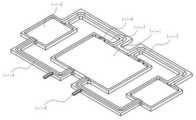
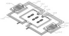
图1是本发明一种环路热管分解图;Fig. 1 is an exploded view of a loop heat pipe of the present invention;
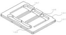
图2为本发明的一体化上板的正面示意图;Fig. 2 is a schematic front view of the integrated upper plate of the present invention;
图3为本发明的一体化上板的反面示意图;Fig. 3 is the reverse schematic view of the integrated upper plate of the present invention;
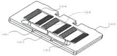
图4为本发明的蒸发器中板的正面示意图;Fig. 4 is the front schematic diagram of plate in the evaporator of the present invention;
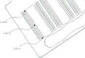
图5为本发明的蒸发器中板的反面示意图;Fig. 5 is the back schematic diagram of plate in the evaporator of the present invention;
图6为本发明的蒸发器中板的局部示意图;Fig. 6 is the local schematic diagram of plate in the evaporator of the present invention;
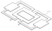
图7为本发明的一体化下板的正面示意图;Fig. 7 is a schematic front view of the integrated lower plate of the present invention;
图8为本发明的一体化下板的反面示意图。Fig. 8 is a schematic view of the reverse side of the integrated lower plate of the present invention.
图1中,1-1为上板,1-2为中板,1-3为下板;In Figure 1, 1-1 is the upper board, 1-2 is the middle board, and 1-3 is the lower board;
图2-3中,1-1-1为蒸发器上板,1-1-2为冷凝器上板,1-1-3上板汽相管路,1-1-4为上板液相管路,1-1-5为充注口,1-1-6为防反插卡口,1-1-7为2°倾斜梯形结构;In Figure 2-3, 1-1-1 is the upper plate of the evaporator, 1-1-2 is the upper plate of the condenser, 1-1-3 is the vapor phase pipeline of the upper plate, and 1-1-4 is the liquid phase of the upper plate Pipeline, 1-1-5 is the filling port, 1-1-6 is the anti-reverse bayonet, 1-1-7 is a 2° inclined trapezoidal structure;
图4-5中,1-2-1为液相入口,1-2-2为储液槽,1-2-3为2°倾斜梯形结构,1-2-4为鱼骨状微通道,1-2-5为防插反卡口,1-2-6为液相通道,1-2-7为蒸汽槽道,1-2-8为气体缓冲腔;In Figure 4-5, 1-2-1 is the liquid phase inlet, 1-2-2 is the liquid storage tank, 1-2-3 is a 2° inclined trapezoidal structure, 1-2-4 is a fishbone microchannel, 1-2-5 is the anti-insertion bayonet, 1-2-6 is the liquid phase channel, 1-2-7 is the steam channel, 1-2-8 is the gas buffer chamber;
图6中,1-2-9为三角形微流道,1-2-10为平行四边形微流道,1-2-11为梯形微流道;In Fig. 6, 1-2-9 is a triangular microchannel, 1-2-10 is a parallelogram microchannel, and 1-2-11 is a trapezoidal microchannel;
图7-8中,1-3-1为蒸发器下板,1-3-2为下板液相管路,1-3-3为下板汽相管路,1-3-4为冷凝器下板,1-3-5为流线型导流模组,1-3-6为防插反卡口,1-3-7为圆滑过渡结构,1-3-8为蒸发腔位置的标识刻线,1-3-9为梭形翅片,1-3-10为叉错式微通道结构;1-3-11为冷凝器下板上阶梯边缘。In Figure 7-8, 1-3-1 is the lower plate of the evaporator, 1-3-2 is the liquid phase pipeline of the lower plate, 1-3-3 is the vapor phase pipeline of the lower plate, and 1-3-4 is the condensation The lower plate of the device, 1-3-5 is a streamlined diversion module, 1-3-6 is an anti-insertion reverse bayonet, 1-3-7 is a smooth transition structure, and 1-3-8 is the logo engraved on the position of the evaporation chamber Lines, 1-3-9 are shuttle-shaped fins, 1-3-10 are cross-staggered microchannel structures; 1-3-11 are step edges on the lower plate of the condenser.
具体实施方式Detailed ways
下面将结合本发明实施例中的附图,对本发明实施例中的技术方案进行补充说明。The technical solutions in the embodiments of the present invention will be supplemented below with reference to the drawings in the embodiments of the present invention.
图1-7公开了一种环路热管。如图1所示,一种组合形成的环路热管,包括上板1-1、中板1-2和下板1-3,所述上板1-1和下板1-3是一体化结构。如图2所示,所述上板1-1包括蒸发器上板1-1-1、冷凝器上板1-1-2、上板汽相管路1-1-3及上板液相管路1-1-4。如图7所示,所述下板1-3包括蒸发器下板1-3-1、冷凝器下板1-3-4、下板汽相管路1-3-3及下板液相管路1-3-2。所述中板1-2是蒸发器的中板,如图4-5所示,中板1-2的下面包括液相入口1-2-1、储液槽1-2-2、微通道1-2-4、液相通道1-2-6,中板上面包括蒸汽槽道1-2-7和气体缓冲腔1-2-8,上板1-1、中板1-2和下板1-3安装在一起形成一个完整的环路热管,其中冷凝器上板与冷凝器下板形成冷凝器,蒸发器上板、中板和蒸发器下板形成蒸发器,上板汽相管路与下板汽相管路形成汽相管路,上板液相管路与下板液相管路形成液相管路;液体在蒸发器吸热,通过蒸汽槽道1-2-7进入气体缓冲腔,然后进入汽相管路,通过汽相管路进入冷凝器中进行冷凝,冷凝后的液体进入液相管路,通过液相入口进入储液槽,然后进入液相通道,从液相通道通过微通道,加热形成蒸汽进入蒸汽槽道。1-7 disclose a loop heat pipe. As shown in Figure 1, a combined loop heat pipe includes an upper plate 1-1, a middle plate 1-2 and a lower plate 1-3, and the upper plate 1-1 and the lower plate 1-3 are integrated structure. As shown in Figure 2, the upper plate 1-1 includes an evaporator upper plate 1-1-1, a condenser upper plate 1-1-2, an upper plate vapor phase pipeline 1-1-3 and an upper plate liquid phase Line 1-1-4. As shown in Figure 7, the lower plate 1-3 includes an evaporator lower plate 1-3-1, a condenser lower plate 1-3-4, a lower plate vapor phase pipeline 1-3-3 and a lower plate liquid phase Line 1-3-2. The middle plate 1-2 is the middle plate of the evaporator, as shown in Figure 4-5, the bottom of the middle plate 1-2 includes a liquid phase inlet 1-2-1, a liquid storage tank 1-2-2, a microchannel 1-2-4, the liquid phase channel 1-2-6, the middle plate includes the steam channel 1-2-7 and the gas buffer chamber 1-2-8, the upper plate 1-1, the middle plate 1-2 and the lower plate Plates 1-3 are installed together to form a complete loop heat pipe, in which the upper plate of the condenser and the lower plate of the condenser form the condenser, the upper plate, the middle plate and the lower plate of the evaporator form the evaporator, and the vapor phase tube of the upper plate The pipeline and the vapor phase pipeline of the lower plate form a vapor phase pipeline, and the liquid phase pipeline of the upper plate and the liquid phase pipeline of the lower plate form a liquid phase pipeline; the liquid absorbs heat in the evaporator and enters through the steam channel 1-2-7 The gas buffer chamber, then enters the vapor phase pipeline, enters the condenser through the vapor phase pipeline for condensation, the condensed liquid enters the liquid phase pipeline, enters the liquid storage tank through the liquid phase inlet, and then enters the liquid phase channel, from the liquid phase The phase channel passes through the micro channel, and the heating forms steam into the steam channel.
作为优选,所述上板1-1和下板1-2是一体化制造。Preferably, the upper plate 1-1 and the lower plate 1-2 are manufactured in one piece.
蒸发器下板、冷凝器下板、汽相管道下板、液相管道下板采用了一体化设计,四者底面在同一个平面,设计在同一个板上,集成效果好,加工难度降低;蒸发器上板、冷凝器上板、汽相管道上板、液相管道上板采用了集成化设计,四者底面在同一个平面,设计在同一个板上,集成效果好,加工难度降低。The lower plate of the evaporator, the lower plate of the condenser, the lower plate of the vapor phase pipeline, and the lower plate of the liquid phase pipeline adopt an integrated design. The bottom surfaces of the four are on the same plane and designed on the same plate. The integration effect is good and the processing difficulty is reduced; The upper plate of the evaporator, the upper plate of the condenser, the upper plate of the vapor phase pipeline, and the upper plate of the liquid phase pipeline adopt an integrated design. The bottom surfaces of the four are on the same plane and are designed on the same plate. The integration effect is good and the processing difficulty is reduced.
作为优选,如图1所示,所述冷凝器为两个,每个冷凝器设置单独的汽相管路和液相管路与蒸发器连接,所述蒸发器设置在两个冷凝器中间。蒸发器设置了连接每个冷凝器的汽相管路和液相管路的单独的入口歧管和出口歧管。Preferably, as shown in FIG. 1 , there are two condensers, and each condenser is provided with a separate vapor phase pipeline and a liquid phase pipeline connected to an evaporator, and the evaporator is arranged between the two condensers. The evaporator is provided with separate inlet and outlet manifolds connecting the vapor and liquid lines of each condenser.
本发明蒸发器采用了歧管设计,由全U型回路转变为半U型回路结构,优化气体流动路径;与传统环路热管相比,减小了毛细路径长度和液相工质的流速,增加液体流过微通道的换热时间,提高了换热效果和换热效率,除此之外,半U型回路歧管结构减小了液相工质流阻,提升传热效果。The evaporator of the present invention adopts a manifold design, which is changed from a full U-shaped circuit to a half-U-shaped circuit structure, and the gas flow path is optimized; compared with the traditional loop heat pipe, the length of the capillary path and the flow rate of the liquid-phase working medium are reduced, Increasing the heat exchange time for the liquid to flow through the microchannel improves the heat exchange effect and heat exchange efficiency. In addition, the semi-U-shaped loop manifold structure reduces the flow resistance of the liquid-phase working medium and improves the heat transfer effect.
作为优选,如图5、6所示,微通道包括鱼骨状微通道肋片,相邻的鱼骨状微通道肋片之间形成微通道;所述肋片分为向流体流动方向一侧倾斜的两排,两排的中间是液相通道,所述两排沿着液相通道对称分布。As preferably, as shown in Figure 5, 6, microchannel comprises fishbone shape microchannel fin, forms microchannel between adjacent fishbone shape microchannel fin; There are two inclined rows, the middle of the two rows is a liquid phase channel, and the two rows are symmetrically distributed along the liquid phase channel.
本发明在一体化下板设置有容纳鱼骨状微通道肋片的空腔,与水平面呈一定夹角,提升了可毛细芯的数量和面积,提升了换热面积,提升换热效率。In the present invention, a cavity for accommodating fishbone-shaped microchannel fins is provided on the integrated lower plate, which forms a certain angle with the horizontal plane, increases the number and area of capillary cores, increases the heat exchange area, and improves heat exchange efficiency.
如图4-5所示,鱼骨状微通道肋片包括多组,液相通道形成在多组肋片之间。鱼骨形翅片结构采用与水平面倾角为20°交错鱼骨式微通道。本发明鱼骨状微通道1-2-4与蒸汽槽道1-2-7对应配合而成,鱼骨形肋片结构采用与水平面倾角为20°交错鱼骨式微通道,使毛细芯等距阵列排布,有效提高散热面积,节省空间,提升换热性能。As shown in Figures 4-5, the fishbone-shaped microchannel fins include multiple groups, and liquid phase channels are formed between the multiple groups of fins. The herringbone fin structure adopts staggered herringbone microchannels with an inclination angle of 20° to the horizontal plane. According to the present invention, the herringbone microchannels 1-2-4 are matched with the steam channel 1-2-7, and the herringbone rib structure adopts staggered herringbone microchannels with an inclination angle of 20° to the horizontal plane, so that the capillary cores are equidistant The array arrangement can effectively increase the heat dissipation area, save space, and improve heat transfer performance.
作为优选,所述鱼骨状微通道肋片与水平面呈一定夹角,在鱼骨状微通道肋片之间填充毛细芯。交错鱼骨式微通道与毛细芯相互配合,在储液槽一侧填充梯形微流道,在气体缓冲腔侧填充三角形毛细芯,在中间部分填充梯形毛细芯。如图6所示,1-2-9为三角形微流道,1-2-10为平行四边形微流道,1-2-11为梯形微流道,分别填充三角形毛细芯、平行四边形毛细芯、梯形毛细芯,肋板与毛细芯过盈配合而成。多种形状毛细芯,有效增大换热面积,提升换热效率。Preferably, the fishbone-shaped microchannel fins form a certain angle with the horizontal plane, and capillary cores are filled between the fishbone-shaped microchannel fins. The staggered herringbone microchannel cooperates with the capillary core, the trapezoidal microchannel is filled on the side of the liquid storage tank, the triangular capillary core is filled on the side of the gas buffer cavity, and the trapezoidal capillary core is filled in the middle part. As shown in Figure 6, 1-2-9 is a triangular microchannel, 1-2-10 is a parallelogram microchannel, and 1-2-11 is a trapezoidal microchannel, which are respectively filled with a triangular capillary core and a parallelogram capillary core. , Trapezoidal capillary core, made of ribs and capillary core with interference fit. Capillary cores of various shapes can effectively increase the heat transfer area and improve the heat transfer efficiency.
本发明设计加工高深宽比微小槽道阵列,优选深宽比为4.5-5.5,进一步优选为5。大幅度提升微型槽道对液相工质的毛细力,以为管内的工质循环提供更多驱动力,使得液相工质可以在复杂的环路热管中实现无能量输入的自循环,毛细芯形状设计平行四边形、三角形、梯形,最大限度利用鱼骨状微通道肋片的空腔面积,提升换热能力。The present invention designs and processes a micro channel array with a high aspect ratio, preferably the aspect ratio is 4.5-5.5, more preferably 5. The capillary force of the micro channel to the liquid-phase working medium is greatly improved to provide more driving force for the circulation of the working medium in the tube, so that the liquid-phase working medium can realize self-circulation without energy input in the complex loop heat pipe, and the capillary core The shape design is parallelogram, triangle, and trapezoid, which maximizes the use of the cavity area of the fishbone-shaped microchannel fins and improves the heat exchange capacity.
本发明通过冷压注入金属粉末,一体化设计毛细芯与蒸发器中板,采用烧结法使毛细芯与中板底板合为一体,多孔结构在增大毛细力、提供驱动力的同时增大换热效率。The invention injects metal powder through cold pressing, integrates the design of the capillary core and the middle plate of the evaporator, and adopts the sintering method to integrate the capillary core and the bottom plate of the middle plate. Thermal efficiency.
作为优选,如图7所示,蒸发器下板设置翅片阵列1-3-9,所述翅片阵列1-3-9呈梭形结构布置。本发明设置了新式的梭形结构翅片,可以使得流体沿着翅片流动,进一步使毛细芯充分浸润,提高了蒸发效率。Preferably, as shown in FIG. 7 , the lower plate of the evaporator is provided with a fin array 1-3-9, and the fin array 1-3-9 is arranged in a shuttle-shaped structure. The present invention is provided with novel shuttle-shaped fins, which can make the fluid flow along the fins, further fully infiltrate the capillary core, and improve the evaporation efficiency.
如图7所示,翅片阵列为多个,相邻的两个翅片阵列进行首尾连接。作为优选,每个翅片阵列分为多层,每个阵列包括中心翅片和围绕中心翅片的多层外围翅片,每层翅片都是梭形结构。通过设置多层,使得流体能够在其中充分流动换热。As shown in FIG. 7 , there are multiple fin arrays, and two adjacent fin arrays are connected end to end. Preferably, each fin array is divided into multiple layers, each array includes a central fin and multiple layers of peripheral fins surrounding the central fin, and each layer of fins is a shuttle-shaped structure. By arranging multiple layers, the fluid can fully flow and exchange heat therein.
多个翅片阵列组成一组,每一组的第一梭形结构的头部与液体的流体方向相对(迎着流体流动方向),第一梭形结构的尾部与第二梭形结构头部连接,以此类推,从而形成一组。通过设置多层,使得流体能够在其中充分流动换热,而且流体的流动通道随着流动不断的沿着梭子形状进行频繁的流动以及体积变化,进一步提高换热效率。Multiple fin arrays form a group, the head of the first shuttle-shaped structure of each group is opposite to the flow direction of the liquid (facing the direction of fluid flow), the tail of the first shuttle-shaped structure is connected to the head of the second shuttle-shaped structure connected, and so on, to form a group. By arranging multiple layers, the fluid can fully flow and exchange heat in it, and the flow channel of the fluid will undergo frequent flow and volume changes along the shape of the shuttle along with the flow, thereby further improving the heat exchange efficiency.
作为优选,梭形结构的头部和尾部都是尖部。Preferably, both the head and the tail of the shuttle-shaped structure are pointed.
作为优选,梭形结构的头部的尖部夹角小于尾部的尖部夹角。同构上述结构,可以使得流体首先沿着梭子形状慢慢的扩散,避免快速扩散带来的换热效果低的特性,促进换热的进行,同时促进流体的引导,使其与前面的毛细结构进一步配合,提高了蒸发效率。Preferably, the included angle of the tip of the head of the shuttle-shaped structure is smaller than the included angle of the tip of the tail. The isomorphic above-mentioned structure can make the fluid diffuse slowly along the shape of the shuttle first, avoiding the low heat exchange effect caused by rapid diffusion, promoting the heat exchange, and promoting the guidance of the fluid at the same time, making it compatible with the previous capillary structure Further cooperation improves the evaporation efficiency.
作为优选,每一组的中心翅片的连线与流体流动方向相同。Preferably, the connecting line of the central fins of each group is in the same direction as the fluid flow.
作为优选,多组翅片阵列平行设置。Preferably, multiple sets of fin arrays are arranged in parallel.
作为优选,翅片阵列设置在多组肋片之间对应的位置。Preferably, the fin arrays are arranged at corresponding positions among multiple sets of ribs.
所述蒸发器下板上表面设置梭形翅片阵列组成的流线型导流模组1-3-5,三组对称分布的翅片宏观上也以梭形分布起到导流的作用,进一步使毛细芯充分浸润,提高了蒸发效率。The upper surface of the lower plate of the evaporator is provided with a streamlined flow diversion module 1-3-5 composed of a shuttle-shaped fin array, and the three groups of symmetrically distributed fins also play the role of flow diversion in a shuttle-shaped distribution on a macroscopic level, further enabling The capillary core is fully infiltrated, which improves the evaporation efficiency.
所述冷凝器下板上表面设置与蒸发器类似的阵列梭形翅片1-3-9,减小液体、气体的流动阻力,翅片宽度与间距比例为1:2,进一步减小流动阻力,同时在同等条件下增大了换热面积,有效提高了冷凝器的换热效率。所述冷凝器下板与汽相、液相管路连接处采用叉错式微通道结构1-3-10,以使进入冷凝器的汽相均匀扩散至各个微通道。The upper surface of the lower plate of the condenser is provided with an array of shuttle fins 1-3-9 similar to those of the evaporator to reduce the flow resistance of liquid and gas. The ratio of fin width to spacing is 1:2 to further reduce the flow resistance , while increasing the heat transfer area under the same conditions, effectively improving the heat transfer efficiency of the condenser. The connection between the lower plate of the condenser and the vapor phase and liquid phase pipelines adopts a crossed microchannel structure 1-3-10, so that the vapor phase entering the condenser can be evenly diffused to each microchannel.
作为优选,冷凝器设置翅片,所述翅片为梭形结构。通过设置梭形结构增大导热面积,提高散热效率,减小汽相工质流阻。Preferably, the condenser is provided with fins, and the fins are in a shuttle-shaped structure. By setting the shuttle structure, the heat conduction area is increased, the heat dissipation efficiency is improved, and the flow resistance of the vapor phase working medium is reduced.
本发明通过梭形翅片阵列组成的流线型导流模组1-3-5与鱼骨形肋片结构的位置协同配合出现新式结构的蒸发器,进一步形成互相配合的液体通道和蒸汽槽道,可以进一步提高蒸发器的换热效率。In the present invention, the streamlined diversion module 1-3-5 formed by the shuttle-shaped fin array cooperates with the position of the herringbone-shaped fin structure to form a new-type evaporator, and further forms a liquid channel and a steam channel that cooperate with each other. The heat exchange efficiency of the evaporator can be further improved.
冷凝器部分采用了叉错式微通道式设计,待冷却的汽相工质更加均匀地扩散到整个冷却腔,提高冷凝效率,确保一个循环内汽相能够转换为液相。The condenser part adopts a cross-staggered micro-channel design, and the vapor-phase working medium to be cooled is more evenly diffused to the entire cooling chamber, which improves the condensation efficiency and ensures that the vapor phase can be converted into a liquid phase within a cycle.
作为优选,所述叉错式结构是指冷凝器入口和冷凝器出口均采用V型结构,相比矩形腔体冷凝器,在不减小流速的前提下,增加与壁面的换热效率。Preferably, the staggered structure means that both the condenser inlet and the condenser outlet adopt a V-shaped structure. Compared with a rectangular cavity condenser, the heat exchange efficiency with the wall surface is increased without reducing the flow rate.
通过进行仿真计算后发现,通过梭形结构配合入口和出口V型结构,相同流速下,相比普通微通道翅片情况下,压降几乎不变的情况下,瞬态的均温性提升效果明显。Through simulation calculations, it is found that through the shuttle structure and the V-shaped structure of the inlet and outlet, at the same flow rate, compared with ordinary microchannel fins, the pressure drop is almost unchanged, and the transient temperature uniformity improvement effect obvious.
作为优选,所述翅片是弹性部件,通过弹性部件可以使得流体流动的时候冲刷导热体,翅片会脉动性的摆动,从而促进除垢,振动导致扰流作用,也能强化传热。Preferably, the fins are elastic components, through which the fluid can scour the heat conductor when the fluid flows, and the fins will swing in a pulsating manner, thereby promoting descaling, and the vibration can cause flow disturbance, which can also enhance heat transfer.
作为优选,沿着冷凝段内的流体流动方向(从冷凝段入口到出口),翅片的弹性先变小后变大。因为随着研究发现,随着蒸汽进入冷凝器,因为体积的突然增加,压力变小,使得部分携带的部分液体也不断形成汽体,从而使得冲击增加,不容易结垢,因此设置弹性开始逐渐降低,随着后续进行换热冷凝,流体更加容易积垢,而且沿着流体流动方向结垢程度越来越严重,因此通过设置弹性程度不断增加,已达到进一步除垢强化传热目的,减少大弹性的导热体,降低成本。通过上述设置,可以进一步快速实现换热和除垢,同时能够节约成本,使得最佳效果和最低成本达到最佳。Preferably, along the direction of fluid flow in the condensation section (from the inlet to the outlet of the condensation section), the elasticity of the fins decreases first and then increases. Because as the research found, as the steam enters the condenser, because of the sudden increase in volume, the pressure becomes smaller, so that part of the carried part of the liquid also continues to form gas, so that the impact increases and it is not easy to scale, so the setting elasticity begins to gradually With the follow-up heat exchange and condensation, the fluid is more prone to fouling, and the degree of fouling along the fluid flow direction is becoming more and more serious. Therefore, the purpose of further scaling and strengthening heat transfer has been achieved by setting the degree of flexibility, and the reduction of large Elastic heat conductor reduces cost. Through the above settings, the heat exchange and descaling can be further rapidly realized, and at the same time, the cost can be saved, so that the best effect and the lowest cost can be achieved.
进一步优选,沿着冷凝段内的流体流动方向(从冷凝段入口到出口),导热体的弹性变小的幅度越来越小,随后变大的幅度不断增加。上述的变化也是根据研究发现的,符合结垢的规律,能够进一步降低成本,提高换热效率,降低结垢。使得最佳效果和最低成本达到最佳。Further preferably, along the fluid flow direction in the condensing section (from the inlet to the outlet of the condensing section), the elasticity of the heat conductor becomes smaller and smaller, and then the elasticity of the heat conductor increases continuously. The above changes are also found according to research, which conforms to the law of fouling, can further reduce costs, improve heat exchange efficiency, and reduce fouling. Make the best effect and the lowest cost to achieve the best.
进一步优选,翅片弹性最小的位置在蒸发器入口和出口之间的五分之一位置处,靠近入口。Further preferably, the position where the elasticity of the fins is the smallest is at one-fifth of the position between the inlet and the outlet of the evaporator, close to the inlet.
作为优选,储液槽1-2-2为上面和下面贯通结构,气体缓冲腔1-2-8不是上面和下面贯通结构。通过如此设置可以减少储液槽与气体缓冲腔的连接,减少液体流入气体缓冲腔内。As a preference, the liquid storage tank 1-2-2 is a through structure from the top to the bottom, and the gas buffer chamber 1-2-8 is not a through structure from the top to the bottom. Such arrangement can reduce the connection between the liquid storage tank and the gas buffer chamber, and reduce the flow of liquid into the gas buffer chamber.
作为优选,所述蒸发器上板的气体缓冲腔对应位置设置防反插卡口。Preferably, anti-reverse insertion bayonets are provided at corresponding positions of the gas buffer chamber on the upper plate of the evaporator.
作为优选,汽相管路与液相管路半径比为1.5:1。Preferably, the radius ratio of the vapor phase pipeline to the liquid phase pipeline is 1.5:1.
作为优选,充注口位于液相管路。Preferably, the filling port is located in the liquid phase pipeline.
作为优选,储液槽和气体缓冲腔是圆弧形。Preferably, the liquid storage tank and the gas buffer chamber are arc-shaped.
所述歧管式蒸发器环路热管,其中一体化上板、蒸发器中板、一体化下板采用拼插与真空钎焊连接。真空钎焊有利于一体化上板、一体化下板以及蒸发器中板相接触的位置焊接缝隙紧密,实现良好密封性,此外显著提高了产品的抗腐蚀性,加工过程无环境污染,生产成本较低,成品率较高,工作面清洁。拼插结构利用防装反卡口,实现一体化上板、蒸发器中板与一体化下板的拼插连接,使得工件密封性能较好。The loop heat pipe of the manifold evaporator, wherein the integrated upper plate, the evaporator middle plate, and the integrated lower plate are connected by splicing and vacuum brazing. Vacuum brazing is conducive to tight welding gaps where the integrated upper plate, integrated lower plate, and evaporator middle plate are in contact, achieving good sealing. In addition, the corrosion resistance of the product is significantly improved, and the processing process has no environmental pollution. The production cost Low, high yield, clean working surface. The interlocking structure utilizes the anti-installation anti-bayonet to realize the interlocking connection of the integrated upper plate, the middle plate of the evaporator and the integrated lower plate, so that the sealing performance of the workpiece is better.
本发明把金属作为各部分原材料,可以通过精密机械加工制成并配合。所述蒸发器中毛细芯也为金属材料,通过真空加热炉利用烧结法制成。The invention uses metal as the raw material of each part, which can be made and matched by precision machining. The capillary core in the evaporator is also made of metal material, which is made by sintering in a vacuum heating furnace.
所述一体化上板,其中将蒸发器上板、冷凝器上板、上板汽相管路、上板液相管路在同一平面一体化成型,利于精加工。The integrated upper plate, wherein the upper plate of the evaporator, the upper plate of the condenser, the vapor phase pipeline of the upper plate, and the liquid phase pipeline of the upper plate are integrally formed on the same plane, which is convenient for finishing.
作为优选,所述歧管式蒸发器环路热管采用一个蒸发器并联两个冷凝器的结构设计,增大冷凝面积,提高冷凝速率,提升换热效率。As a preference, the loop heat pipe of the manifold evaporator adopts a structural design in which one evaporator is connected in parallel with two condensers, so as to increase the condensation area, increase the condensation rate, and improve the heat exchange efficiency.
作为优选,如图2所示,所述一体化上板1-1包括蒸发器上板、冷凝器上板、上板汽相管路及上板液相管路。Preferably, as shown in FIG. 2 , the integrated upper plate 1 - 1 includes an upper plate of the evaporator, an upper plate of the condenser, a vapor phase pipeline of the upper plate and a liquid phase pipeline of the upper plate.
所述蒸发器上板包括气体缓冲腔,其中气体缓冲腔和一体化下板设置微通道的腔室对应相配合,一体化上板汽相管路1-1-3与一体化下板汽相管路相对应,上板液相管路1-1-4与一体化下板液相管路相配合,从而形成一个完整的歧管式蒸发器环路热管结构。The upper plate of the evaporator includes a gas buffer chamber, wherein the gas buffer chamber and the microchannel chamber of the integrated lower plate are correspondingly matched, and the integrated upper plate vapor phase pipeline 1-1-3 is connected with the integrated lower plate vapor phase Corresponding to the pipelines, the liquid phase pipelines 1-1-4 on the upper plate cooperate with the liquid phase pipelines on the integrated lower plate to form a complete manifold evaporator loop heat pipe structure.
作为优选,所述蒸发器上板的液相管路1-1-4不与气体缓冲腔连通。不连通区域与蒸发器下板部分微通道紧密贴合,保证气体缓冲腔中产生的蒸汽始终从汽相管路流出,不会回流,保证装置启动后蒸发器内毛细压力平衡不被破坏。Preferably, the liquid phase pipeline 1-1-4 of the upper plate of the evaporator is not connected with the gas buffer chamber. The disconnected area fits closely with the microchannels on the lower plate of the evaporator to ensure that the steam generated in the gas buffer chamber always flows out from the vapor phase pipeline without backflow, and ensures that the capillary pressure balance in the evaporator is not damaged after the device is started.
作为优选,所述蒸发器上板的气体缓冲腔设置防反插卡口1-1-6,便于判断安装的方向。As a preference, the gas buffer cavity on the upper plate of the evaporator is provided with an anti-reverse insertion bayonet 1-1-6, which is convenient for judging the installation direction.
作为优选,如图2所示上板汽相管路1-1-3与上板液相管路1-1-4半径比为1.5:1,优选此比例有利于控制流体流速,提高相变效率。As a preference, as shown in Figure 2, the radius ratio of the upper plate vapor phase pipeline 1-1-3 and the upper plate liquid phase pipeline 1-1-4 is 1.5:1, preferably this ratio is conducive to controlling the fluid flow rate and improving the phase transition efficiency.
作为优选,如图2所示,充注口1-1-5均位于液相管路段,密封性良好,无漏气隐患,有利于充注。Preferably, as shown in Fig. 2, the filling ports 1-1-5 are all located in the liquid phase pipeline section, which has good sealing performance and no hidden danger of air leakage, which is conducive to filling.
作为优选,封装处设置阶梯型边缘,有利于保证密封性。如图2所示,封装处1-1-7采用2°削边设计,V型自动定心,有利于封装。Preferably, a stepped edge is provided at the package, which is beneficial to ensure sealing. As shown in Figure 2, the packaging part 1-1-7 adopts a 2° chamfering design, and the V-shaped self-centering is conducive to packaging.
作为优选,如图4-5所示,所述蒸发器中板1-2包括液相入口1-2-1、储液槽1-2-2、鱼骨状微通道1-2-4、防插反卡口1-2-5、液相通道1-2-6、蒸汽槽道1-2-7、气体缓冲腔1-2-8,其中交错鱼骨式翅片结构与毛细芯对应配合。Preferably, as shown in Figure 4-5, the evaporator middle plate 1-2 includes a liquid phase inlet 1-2-1, a liquid storage tank 1-2-2, a fishbone microchannel 1-2-4, Anti-insertion reverse bayonet 1-2-5, liquid phase channel 1-2-6, steam channel 1-2-7, gas buffer chamber 1-2-8, in which the staggered herringbone fin structure corresponds to the capillary core Cooperate.
作为优选,如图4所示,所述储液槽1-2-2内部设计为平滑圆弧形储液腔,对散热工质起到缓冲作用,减少液体流动阻力,同时起到导流作用,便于散热工质流入蒸发槽。散热工质由液相管路进入储液槽,从而通过液相管路进入鱼骨状微通道。储液槽所连接两个直径液相入口管路与三个液相出口管路,作为优选,液相入口管路和出口管路直径不同,出口管路的数量多于入口管路,直径小于入口管路。对两侧液相管路进行变径设计,控制散热工质流速,实现缓冲功能,进而控制蒸发器内散热工质的汽化程度,提高换热效率。As a preference, as shown in Figure 4, the interior of the liquid storage tank 1-2-2 is designed as a smooth arc-shaped liquid storage cavity, which can buffer the heat dissipation working medium, reduce the flow resistance of the liquid, and at the same time play the role of diversion , to facilitate the flow of cooling fluid into the evaporation tank. The heat dissipation working medium enters the liquid storage tank from the liquid phase pipeline, and then enters the fishbone microchannel through the liquid phase pipeline. The liquid storage tank is connected with two diameter liquid phase inlet pipelines and three liquid phase outlet pipelines. As a preference, the diameters of the liquid phase inlet pipelines and outlet pipelines are different, the number of outlet pipelines is more than that of the inlet pipelines, and the diameter is less than Inlet piping. The diameter of the liquid phase pipeline on both sides is changed to control the flow rate of the heat dissipation working medium to realize the buffer function, and then control the vaporization degree of the heat dissipation working medium in the evaporator to improve the heat exchange efficiency.
作为优选,储液槽所连接两个直径2mm液相入口管路与三个1mm液相出口管路。Preferably, the liquid storage tank is connected with two liquid phase inlet pipelines with a diameter of 2 mm and three liquid phase outlet pipelines with a diameter of 1 mm.
作为优选,作为优选,所述蒸发器中板内部结构均根据位置采用了2mm、1mm、0.5mm导圆角,简化制作工艺,降低制造成本。As a preference, as a preference, the internal structure of the middle plate of the evaporator adopts 2mm, 1mm, 0.5mm fillet according to the position, which simplifies the manufacturing process and reduces the manufacturing cost.
作为优选,如图4所示,所述防插反卡口1-2-5结构,防止蒸发器中板插反,与所述一体化上板、一体化下板防装反卡口相对应,便于蒸发器中板定位。As a preference, as shown in Figure 4, the anti-insertion and reverse bayonet 1-2-5 structure prevents the reverse insertion of the middle plate of the evaporator, and corresponds to the anti-installation and reverse bayonet of the integrated upper plate and integrated lower plate , to facilitate the positioning of the plate in the evaporator.
作为优选,如图4所示,蒸汽槽道1-2-7与气体缓冲腔1-2-8连接,气体缓冲腔用于缓冲散热工质,气体缓冲腔内圆角设计,减小阻力,引流散热工质进入气体缓冲腔。蒸发器中板上层蒸汽槽道采用镂空式设计,部分毛细芯遮挡、部分毛细芯露出,工质循环时受热上升,构成歧管结构,优化传热路径,提升散热效率。As a preference, as shown in Figure 4, the steam channel 1-2-7 is connected to the gas buffer chamber 1-2-8, the gas buffer chamber is used to buffer the heat dissipation working fluid, the rounded corners of the gas buffer chamber are designed to reduce resistance, The cooling fluid is drained into the gas buffer chamber. The upper steam channel on the middle plate of the evaporator adopts a hollow design, part of the capillary core is covered, and part of the capillary core is exposed. When the working medium is heated, it rises to form a manifold structure, optimize the heat transfer path, and improve the heat dissipation efficiency.
作为优选,一体化上板、蒸发器中板、一体化下板封装时,采用阶梯型边缘,利于保证密封性。如图4所示,蒸发器中板封装处1-2-3采用2°削边设计,V型自动定心设计,利于蒸发器中板定位,与一体化上板、一体化下板相配合,便于封装。Preferably, when the integrated upper plate, the evaporator middle plate, and the integrated lower plate are packaged, a stepped edge is used to ensure airtightness. As shown in Figure 4, the packaging part 1-2-3 of the middle plate of the evaporator adopts a 2° chamfering design, and a V-shaped automatic centering design, which facilitates the positioning of the middle plate of the evaporator and matches with the integrated upper plate and integrated lower plate , for easy packaging.
如图6所示,交错鱼骨式微通道与毛细芯相互配合,1-2-9为三角形微流道,1-2-10为平行四边形微流道,1-2-11为梯形微流道,分别填充三角形毛细芯、平行四边形毛细芯、梯形毛细芯,肋板与毛细芯过盈配合而成。多种形状毛细芯,有效增大换热面积,提升换热效率。As shown in Figure 6, interlaced herringbone microchannels and capillary cores cooperate with each other, 1-2-9 is a triangular microchannel, 1-2-10 is a parallelogram microchannel, and 1-2-11 is a trapezoidal microchannel , respectively filled with triangular capillary core, parallelogram capillary core, trapezoidal capillary core, rib plate and capillary core interference fit. Capillary cores of various shapes can effectively increase the heat transfer area and improve the heat transfer efficiency.
如图7所示,所述一体化下板包括蒸发器下板1-3-1、下板液相管路1-3-2、冷凝器下板1-3-4和下板汽相管路1-3-3。As shown in Figure 7, the integrated lower plate includes the evaporator lower plate 1-3-1, the lower plate liquid phase pipeline 1-3-2, the condenser lower plate 1-3-4 and the lower plate vapor phase tube Road 1-3-3.
所述蒸发器下板上表面设置梭形翅片阵列组成的流线型导流模组1-3-5,三组对称分布的翅片宏观上也以梭形分布起到导流的作用,进一步使毛细芯充分浸润,提高了蒸发效率。The upper surface of the lower plate of the evaporator is provided with a streamlined flow diversion module 1-3-5 composed of a shuttle-shaped fin array, and the three groups of symmetrically distributed fins also play the role of flow diversion in a shuttle-shaped distribution on a macroscopic level, further enabling The capillary core is fully infiltrated, which improves the evaporation efficiency.
作为优选,所述蒸发器下板内壁设有防反插卡口1-3-6,侧壁竖直方向倾斜2°,以与其他部件正确配合,同时保证气密性。作为优选,所述蒸发器下板与汽相管路轴心高度不同,在相接处采取圆滑过渡结构1-3-7。As a preference, the inner wall of the lower plate of the evaporator is provided with anti-reverse insertion bayonets 1-3-6, and the side wall is vertically inclined at 2° to properly cooperate with other components while ensuring airtightness. Preferably, the height of the lower plate of the evaporator is different from that of the axis of the vapor phase pipeline, and a smooth transition structure 1-3-7 is adopted at the junction.
作为优选,所述蒸发器下板下表面处刻有0.1mm的蒸发腔位置的标识刻线1-3-8,同时下底面粗糙度较小,利于与热源位置相定位配对且与充分接触减小热阻。As a preference, the lower surface of the lower plate of the evaporator is engraved with 0.1mm marking lines 1-3-8 for the location of the evaporation chamber, and the roughness of the lower bottom surface is relatively small, which is conducive to matching with the location of the heat source and reducing the need for sufficient contact. Small thermal resistance.
所述冷凝器下板上表面阵列梭形翅片1-3-9,减小液体、气体的流动阻力,翅片宽度与间距比例为1:2,进一步减小流动阻力,同时在同等条件下增大了换热面积,有效提高了冷凝器的换热效率。所述冷凝器下板与汽相、液相管路连接处采用叉错式微通道结构1-3-10,以使进入冷凝器的汽相均匀扩散至各个微通道。The array of shuttle fins 1-3-9 on the upper surface of the lower plate of the condenser reduces the flow resistance of liquid and gas. The ratio of fin width to spacing is 1:2, which further reduces the flow resistance. The heat exchange area is enlarged, and the heat exchange efficiency of the condenser is effectively improved. The connection between the lower plate of the condenser and the vapor phase and liquid phase pipelines adopts a crossed microchannel structure 1-3-10, so that the vapor phase entering the condenser can be evenly diffused to each microchannel.
作为优选,所述冷凝器下板上阶梯边缘1-3-11采用2mm圆角设计,既能保证设备气密性,又同时利于与冷凝器上板的配合。As a preference, the step edge 1-3-11 on the lower plate of the condenser adopts a 2mm rounded corner design, which can not only ensure the airtightness of the equipment, but also facilitate the cooperation with the upper plate of the condenser.
上述实施例只为说明本发明的技术构思及特点,其目的在于让熟悉此项技术的人士能够了解本发明的内容并据以实施,并不能以此限制本发明的保护范围。凡根据本发明精神实质所做的等效变化或修饰,都应涵盖在本发明的保护范围之内。The above-mentioned embodiments are only to illustrate the technical concept and characteristics of the present invention, and the purpose is to enable those skilled in the art to understand the content of the present invention and implement it accordingly, and not to limit the protection scope of the present invention. All equivalent changes or modifications made according to the spirit of the present invention shall fall within the protection scope of the present invention.
Claims (9)
Translated fromChinesePriority Applications (1)
| Application Number | Priority Date | Filing Date | Title |
|---|---|---|---|
| CN202210267306.8ACN115993065B (en) | 2022-03-18 | 2022-03-18 | Fishbone-shaped micro-channel evaporator and loop heat pipe thereof |
Applications Claiming Priority (1)
| Application Number | Priority Date | Filing Date | Title |
|---|---|---|---|
| CN202210267306.8ACN115993065B (en) | 2022-03-18 | 2022-03-18 | Fishbone-shaped micro-channel evaporator and loop heat pipe thereof |
Publications (2)
| Publication Number | Publication Date |
|---|---|
| CN115993065Atrue CN115993065A (en) | 2023-04-21 |
| CN115993065B CN115993065B (en) | 2024-05-14 |
Family
ID=85989318
Family Applications (1)
| Application Number | Title | Priority Date | Filing Date |
|---|---|---|---|
| CN202210267306.8AActiveCN115993065B (en) | 2022-03-18 | 2022-03-18 | Fishbone-shaped micro-channel evaporator and loop heat pipe thereof |
Country Status (1)
| Country | Link |
|---|---|
| CN (1) | CN115993065B (en) |
Cited By (2)
| Publication number | Priority date | Publication date | Assignee | Title |
|---|---|---|---|---|
| CN116576703A (en)* | 2023-05-11 | 2023-08-11 | 广东思泉热管理技术有限公司 | Preparation process of vapor chamber with fishbone-shaped capillary structure and product thereof |
| CN119997445A (en)* | 2025-01-23 | 2025-05-13 | 中国电子科技集团公司第十五研究所 | A multi-channel loop heat pipe and radiator |
Citations (8)
| Publication number | Priority date | Publication date | Assignee | Title |
|---|---|---|---|---|
| US20070085227A1 (en)* | 2005-10-13 | 2007-04-19 | Tonkovich Anna L | Multi-phase contacting process using microchannel technology |
| CN101738011A (en)* | 2009-12-15 | 2010-06-16 | 清华大学 | Microfine multi-channel heat pump type air-conditioner heat exchanger with automatic liquid distribution structure |
| CN103089335A (en)* | 2013-01-21 | 2013-05-08 | 上海交通大学 | W-shaped rib channel cooling structure suitable for turbine blade backside cooling cavity |
| CN107677152A (en)* | 2017-09-19 | 2018-02-09 | 电子科技大学 | A kind of Micro-channel Liquid-cooling Cold Plate |
| CN110195988A (en)* | 2018-02-27 | 2019-09-03 | 新光电气工业株式会社 | Plate loop circuit heat pipe |
| JP2020153553A (en)* | 2019-03-19 | 2020-09-24 | 株式会社フジクラ | Method for manufacturing heat exchange structure and heat exchange structure |
| CN212695142U (en)* | 2020-09-28 | 2021-03-12 | 董潇潇 | Microchannel heat sink with interrupted inclined rib structure |
| CN213304108U (en)* | 2020-06-04 | 2021-05-28 | 北京工业大学 | Multi-layer composite nano-porous evaporator |
- 2022
- 2022-03-18CNCN202210267306.8Apatent/CN115993065B/enactiveActive
Patent Citations (8)
| Publication number | Priority date | Publication date | Assignee | Title |
|---|---|---|---|---|
| US20070085227A1 (en)* | 2005-10-13 | 2007-04-19 | Tonkovich Anna L | Multi-phase contacting process using microchannel technology |
| CN101738011A (en)* | 2009-12-15 | 2010-06-16 | 清华大学 | Microfine multi-channel heat pump type air-conditioner heat exchanger with automatic liquid distribution structure |
| CN103089335A (en)* | 2013-01-21 | 2013-05-08 | 上海交通大学 | W-shaped rib channel cooling structure suitable for turbine blade backside cooling cavity |
| CN107677152A (en)* | 2017-09-19 | 2018-02-09 | 电子科技大学 | A kind of Micro-channel Liquid-cooling Cold Plate |
| CN110195988A (en)* | 2018-02-27 | 2019-09-03 | 新光电气工业株式会社 | Plate loop circuit heat pipe |
| JP2020153553A (en)* | 2019-03-19 | 2020-09-24 | 株式会社フジクラ | Method for manufacturing heat exchange structure and heat exchange structure |
| CN213304108U (en)* | 2020-06-04 | 2021-05-28 | 北京工业大学 | Multi-layer composite nano-porous evaporator |
| CN212695142U (en)* | 2020-09-28 | 2021-03-12 | 董潇潇 | Microchannel heat sink with interrupted inclined rib structure |
Cited By (2)
| Publication number | Priority date | Publication date | Assignee | Title |
|---|---|---|---|---|
| CN116576703A (en)* | 2023-05-11 | 2023-08-11 | 广东思泉热管理技术有限公司 | Preparation process of vapor chamber with fishbone-shaped capillary structure and product thereof |
| CN119997445A (en)* | 2025-01-23 | 2025-05-13 | 中国电子科技集团公司第十五研究所 | A multi-channel loop heat pipe and radiator |
Also Published As
| Publication number | Publication date |
|---|---|
| CN115993065B (en) | 2024-05-14 |
Similar Documents
| Publication | Publication Date | Title |
|---|---|---|
| CN116007416B (en) | A manifold evaporator loop heat pipe | |
| CN115993065B (en) | Fishbone-shaped micro-channel evaporator and loop heat pipe thereof | |
| CN115876010B (en) | A loop heat pipe formed by combination | |
| CN204649044U (en) | A kind of follow-on ultra-thin loop circuit heat pipe | |
| CN107062963B (en) | A kind of alternating expression micro-channel condenser for hair cell regeneration | |
| CN110081750A (en) | A kind of pulsating heat pipe with nozzle arrangements | |
| CN104880107B (en) | A kind of follow-on ultra-thin loop circuit heat pipe | |
| CN116007417B (en) | A shuttle array fin evaporator and loop heat pipe thereof | |
| CN207881545U (en) | A kind of novel plate-fin heat exchanger fin | |
| CN110243081A (en) | A solar loop heat pipe system for microbial soil purification | |
| CN116858003B (en) | A condenser and residual heat recovery system | |
| CN113137786A (en) | Membrane tube bank falling film evaporation tube bundle | |
| CN117073430B (en) | Plate heat exchanger with multi-baffle straight plates | |
| CN116858004B (en) | A waste heat system liquid storage device and waste heat recovery system | |
| CN116858001B (en) | Evaporator and waste heat recovery system thereof | |
| CN216592923U (en) | Plate type pulsating heat pipe radiator of condensation end integrated plate type heat exchanger | |
| CN116858002B (en) | A waste heat recovery loop heat pipe system | |
| CN111954445B (en) | Ribbed column type efficient phase change cooling device and cooling method thereof | |
| CN212511920U (en) | High-efficient heating and refrigerating device formed by combining semiconductor wafers | |
| CN110779371B (en) | A water-cooled tube plate heat exchanger with optimal distribution of fluid inlet and outlet | |
| CN111397414A (en) | Loop heat pipe heat accumulator | |
| CN118936176A (en) | A manifold evaporator loop heat pipe | |
| CN114894015B (en) | A heat pipe vapor chamber and its heat exchange system | |
| CN217403228U (en) | Flat loop heat pipe | |
| CN115143821B (en) | Phase change heat transfer mechanism and device capable of utilizing heat-power conversion effect |
Legal Events
| Date | Code | Title | Description |
|---|---|---|---|
| PB01 | Publication | ||
| PB01 | Publication | ||
| SE01 | Entry into force of request for substantive examination | ||
| SE01 | Entry into force of request for substantive examination | ||
| GR01 | Patent grant | ||
| GR01 | Patent grant |