CN115990551A - Method for producing a jet of liquid glue - Google Patents
Method for producing a jet of liquid glueDownload PDFInfo
- Publication number
- CN115990551A CN115990551ACN202111219210.6ACN202111219210ACN115990551ACN 115990551 ACN115990551 ACN 115990551ACN 202111219210 ACN202111219210 ACN 202111219210ACN 115990551 ACN115990551 ACN 115990551A
- Authority
- CN
- China
- Prior art keywords
- glue
- target object
- liquid
- dispensing
- jet
- Prior art date
- Legal status (The legal status is an assumption and is not a legal conclusion. Google has not performed a legal analysis and makes no representation as to the accuracy of the status listed.)
- Pending
Links
Images


Landscapes
- Coating Apparatus (AREA)
Abstract
Description
Translated fromChinese技术领域technical field
本发明涉及点胶技术领域,尤其涉及一种附着液体胶在目标物体的方法。本发明还进一步涉及一种制备液体胶射流的方法。The invention relates to the technical field of glue dispensing, in particular to a method for attaching liquid glue to a target object. The invention still further relates to a method of preparing a liquid glue jet.
背景技术Background technique
点胶,也被称为施胶、涂胶、灌胶、滴胶等,是把胶水等粘合剂涂抹、灌封、点滴到产品上,以起到粘贴、灌封、固定、绝缘、光滑表面等作用。点胶工艺的应用范围非常广泛,在包括汽车、船舶、飞行器、电气元件、家居家装、衣装鞋帽等诸多行业相关产品的生产制造过程中,均可能涉及到点胶工艺的使用。Glue dispensing, also known as sizing, gluing, glue pouring, glue dropping, etc., is to apply, potting, and dripping glue and other adhesives on the product to play the role of pasting, potting, fixing, insulating, and smoothing. surface etc. The application range of the dispensing process is very wide. The use of the dispensing process may be involved in the production and manufacturing of products related to many industries, including automobiles, ships, aircraft, electrical components, home improvement, clothing, shoes and hats.
现有的点胶方式也有多种,如手动点胶、胶枪点胶、点胶机点胶等。人工点胶或胶枪点胶,方法简单,但需要大量人工,且难以实现高精度控制。自动化点胶机,如现有的智能视觉定位点胶机,可实现对需要点胶的目标物体进行精确定位和点胶路线的三维控制,点胶量、点胶路径、涂胶速度和点胶时间均可实现较高精度的自动控制。然而,大部分现有点胶机有下述诸多缺陷:首先,现有点胶机在点胶时,是通过施加在胶液的压力,将其自出胶口挤出和使其附着在附着面。因此,现有的点胶机,尤其是其出胶口与目标物体之间的距离较大时,易产生散点和扩散到其它部位。现有点胶机的胶液挤出也导致其流量不易实现精确控制。其次,现有点胶机对点胶高度较为敏感。为了实现比较好的点胶效果,现有点胶机的出胶口与目标物体之间的距离不能过大,一般不能大于3倍点胶(胶线)厚度。点胶机的出胶口与目标物体之间的距离过大,可能导致液体胶扩散和侵入到非点胶部位。尤其是当液体胶的粘度较大时,液体胶很容易因为拖胶、拉丝导致液体胶被附着在非预期部位。其次,现有点胶机的胶线宽度受到点胶机的胶针的针口(或(或喷射器的出胶口)的内径大小的限制,难以实现超细(胶线)点胶。现有大部分点胶机的点胶(胶线)宽度大于胶针针口内径1.5倍大小,最小点胶(胶线)宽度在150um。再次,现有的点胶机对胶液附着面的平整度和一致性要求较高,在对凸凹不平表面点胶时,效果较差。最后,现有的绝大部分的点胶机的功能实现单一。例如,接触式点胶机需要更换胶针(甚至是整个点胶系统)才能实现非接触点胶,喷雾点胶需要专门的雾化阀才能实现,且在液体胶粘度过大时,很容易导致液体胶难以雾化和在空间上的分布不均。There are also many existing dispensing methods, such as manual dispensing, glue gun dispensing, dispensing machine dispensing, etc. Manual dispensing or glue gun dispensing is a simple method, but it requires a lot of labor and it is difficult to achieve high-precision control. Automatic dispensing machine, such as the existing intelligent visual positioning dispensing machine, can realize the precise positioning of the target object that needs dispensing and the three-dimensional control of dispensing route, dispensing amount, dispensing path, dispensing speed and dispensing Time can achieve higher precision automatic control. However, most of the existing glue dispensers have the following defects: first, when the existing glue dispensers are dispensing glue, they are extruded from the glue outlet and attached to the glue by the pressure applied to the glue. noodle. Therefore, existing dispensing machines, especially when the distance between the glue outlet and the target object is relatively large, are prone to scatter and spread to other positions. Extrusion of glue from existing glue dispensers also makes it difficult to precisely control the flow rate. Secondly, existing dispensing machines are more sensitive to dispensing height. In order to achieve a better dispensing effect, the distance between the glue outlet of the existing dispensing machine and the target object should not be too large, generally not greater than 3 times the thickness of the dispensing (glue line). The distance between the glue outlet of the dispenser and the target object is too large, which may cause liquid glue to spread and invade into non-dispensing parts. Especially when the viscosity of the liquid glue is high, the liquid glue is easy to be attached to unexpected parts due to dragging and drawing. Secondly, the width of the glue line of the existing glue dispenser is limited by the inner diameter of the needle mouth of the glue dispenser (or (or the glue outlet of the injector)), and it is difficult to achieve ultra-fine (glue line) dispensing. Now The dispensing (glue line) width of most dispensing machines is 1.5 times larger than the inner diameter of the needle mouth of the glue needle, and the minimum dispensing (glue line) width is 150um. Again, the existing dispensing machines have a high degree of flatness on the glue attachment surface. The requirements for accuracy and consistency are high, and the effect is poor when dispensing on uneven surfaces. Finally, most of the existing dispensing machines have a single function. For example, the contact dispensing machine needs to replace the glue needle ( Even the entire dispensing system) to achieve non-contact dispensing, spray dispensing requires a special atomization valve to achieve, and when the viscosity of the liquid glue is too high, it is easy to cause the liquid glue to be difficult to atomize and distribute in space uneven.
申请号为CN201710589870.0的中国发明专利公开了一种点胶设备及其点胶方法,其中该点胶设备包括点胶台、横向气缸、纵向气缸、升降气缸、调节柱、点胶装置和调节筒等元件和部件,通过气缸调节目标物体与点胶装置之间的距离和出胶量和实现液体胶的点胶。然而,该发明专利公开的点胶设备相比其他现有点胶设备并无显著改进,且其通过气缸控制点胶量,难以实现点胶量的精细控制,在对凸凹不平表面点胶时,效果较差,对点胶高度敏感,功能实现单一,无法降低胶线宽度。The Chinese invention patent with the application number CN201710589870.0 discloses a dispensing equipment and its dispensing method, wherein the dispensing equipment includes a dispensing table, a horizontal cylinder, a vertical cylinder, a lifting cylinder, an adjustment column, a dispensing device and an adjustment Components and components such as cylinders, adjust the distance between the target object and the dispensing device and the amount of glue through the cylinder, and realize the dispensing of liquid glue. However, the dispensing equipment disclosed in this invention patent has no significant improvement compared with other existing dispensing equipment, and it controls the dispensing amount through the cylinder, which makes it difficult to achieve fine control of the dispensing amount. When dispensing on uneven surfaces, The effect is poor, highly sensitive to dispensing, and the function is single, and the width of the glue line cannot be reduced.
申请号为CN201410673269.6的中国发明专利公开了一种控制光敏胶粘度的点胶方法及其点胶系统,其中该点胶系统包括控制系统、点胶泵、三维控制平台紫外光源等结构。该发明专利解决了贴合成型中的UV胶扩展问题和被涂胶的目标物体的三维空间移动和预设位置点胶问题。然而,该发明专利公开的控制光敏胶粘度的点胶方法及其点胶系统也未能解决上述现有点胶机的无法实现点胶量的精细控制,在对凸凹不平表面点胶时,效果较差,对点胶高度敏感,功能实现单一,无法降低胶线宽度等问题。The Chinese invention patent with the application number CN201410673269.6 discloses a dispensing method and dispensing system for controlling the viscosity of photosensitive adhesive, wherein the dispensing system includes a control system, a dispensing pump, a three-dimensional control platform, and an ultraviolet light source. This invention patent solves the problem of UV glue expansion in lamination molding and the three-dimensional space movement and preset position dispensing of the glued target object. However, the dispensing method and its dispensing system for controlling the viscosity of the photosensitive adhesive disclosed in this invention patent also fail to solve the above-mentioned existing dispensing machines that cannot realize the fine control of the dispensing amount. When dispensing glue on uneven surfaces, The effect is poor, it is highly sensitive to dispensing, the function is single, and the width of the glue line cannot be reduced.
发明内容Contents of the invention
本发明的主要优势是提供一种制备液体胶射流的方法,其中本发明制备液体胶射流的方法能够在电压作用下使该液体胶形成的流体进一步形成射向目标物体的射流,以使该流体胶能够通过射向目标物体的射流附着在目标物体的胶附着面。The main advantage of the present invention is to provide a method for preparing liquid glue jet, wherein the method for preparing liquid glue jet of the present invention can make the fluid formed by the liquid glue further form a jet directed at the target object under the action of voltage, so that the fluid The glue can be attached to the glue-attached surface of the target object by the jet directed at the target object.
本发明的另一优势是提供一种附着液体胶在目标物体的方法,其中本发明附着液体胶在目标物体的方法能够在电压作用下使该液体胶形成的流体进一步形成射向目标物体的射流,从而使该流体胶能够附着在目标物体的胶附着面。Another advantage of the present invention is to provide a method for attaching liquid glue to a target object, wherein the method for attaching liquid glue to a target object in the present invention can make the fluid formed by the liquid glue further form a jet directed at the target object under the action of voltage , so that the fluid glue can adhere to the glue attachment surface of the target object.
本发明的另一优势是提供一种附着液体胶在目标物体的方法,其中本发明附着液体胶在目标物体的方法更容易实现液体胶点胶量的高精度控制,和不易扩散和侵入到目标物体的非点胶部位。Another advantage of the present invention is to provide a method of attaching liquid glue to a target object, wherein the method of attaching liquid glue to a target object in the present invention is easier to achieve high-precision control of the amount of liquid glue dispensed, and is not easy to spread and invade into the target The non-dispensing part of the object.
本发明的另一优势是提供一种附着液体胶在目标物体的方法,其中本发明附着液体胶在目标物体的方法的点胶效果受点胶高度的影响较小,其允许胶针的出胶口(或喷嘴)与目标物体之间的距离可以更远。这有利于使用者或操作人员精确控制点胶。Another advantage of the present invention is to provide a method for attaching liquid glue to a target object, wherein the dispensing effect of the method for attaching liquid glue to a target object of the present invention is less affected by the height of the dispensing glue, which allows the glue out of the glue needle The distance between the mouth (or nozzle) and the target object can be further. This facilitates precise control of dispensing by the user or operator.
本发明的另一优势是提供一种附着液体胶在目标物体的方法,其中本发明附着液体胶在目标物体的方法使操作人员或使用者可通过单个胶针实现接触式点胶、非接触式点胶和喷雾点胶。Another advantage of the present invention is to provide a method of attaching liquid glue to the target object, wherein the method of attaching liquid glue to the target object of the present invention enables the operator or user to realize contact dispensing, non-contact dispensing through a single glue needle. Dispensing and spray dispensing.
本发明的另一优势是提供一种附着液体胶在目标物体的方法,其中本发明附着液体胶在目标物体的方法中的胶线宽度大小可被控制小于点胶机的出胶口的内径大小。换句话说,本发明附着液体胶在目标物体的方法可更精细控制点胶,尤其是更好地控制胶线宽度。Another advantage of the present invention is to provide a method of attaching liquid glue to a target object, wherein the width of the glue line in the method of attaching liquid glue to a target object of the present invention can be controlled to be smaller than the inner diameter of the glue outlet of the dispenser . In other words, the method of attaching liquid glue to the target object of the present invention can control the dispensing more finely, especially better control the glue line width.
本发明的另一优势是提供一种附着液体胶在目标物体的方法,其中本发明附着液体胶在目标物体的方法在实施喷雾点胶时,液体胶可更加均匀地分布在目标物体的点胶部位(或胶附着面)。Another advantage of the present invention is to provide a method for attaching liquid glue to a target object, wherein the method of attaching liquid glue to a target object in the present invention can distribute the liquid glue more evenly on the target object during spray dispensing part (or adhesive attachment surface).
本发明的另一优势是提供一种附着液体胶在目标物体的方法,其中本发明附着液体胶在目标物体的方法即使在凸凹不平的表面点胶,也可获得良好点胶效果。Another advantage of the present invention is to provide a method of attaching liquid glue to a target object, wherein the method of attaching liquid glue to a target object of the present invention can obtain good dispensing effect even when dispensing glue on uneven surfaces.
本发明的其它目的和特点通过下述的详细说明得以充分体现。Other objects and features of the present invention will be fully manifested through the following detailed description.
相应地,本发明提供一种制备液体胶射流的方法,其包括下述步骤:Correspondingly, the present invention provides a kind of method for preparing liquid glue jet, it comprises the steps:
使该液体胶形成一流体;和forming the liquid glue into a fluid; and
施加一预设电压在该流体,以使该流体能够形成一射流,其中该射流的直径为30μm-1000μm。A preset voltage is applied to the fluid so that the fluid can form a jet, wherein the diameter of the jet is 30 μm-1000 μm.
结合下述描述和说明书附图,本发明上述的和其它的优势将得以充分体现。The above and other advantages of the present invention will be fully manifested in conjunction with the following description and accompanying drawings.
本发明上述的和其它的优势和特点,通过下述对本发明的详细说明和说明书附图得以充分体现。The above and other advantages and features of the present invention are fully embodied through the following detailed description of the present invention and the accompanying drawings.
附图说明Description of drawings
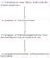
图1A是根据本发明实施例的附着液体胶在目标物体的方法的流程图。FIG. 1A is a flowchart of a method for attaching liquid glue to a target object according to an embodiment of the present invention.
图1B是根据本发明实施例的另一附着液体胶在目标物体的方法的流程图。FIG. 1B is a flowchart of another method for attaching liquid glue to a target object according to an embodiment of the present invention.
图1C是根据本发明实施例的另一附着液体胶在目标物体的方法的流程图。FIG. 1C is a flowchart of another method for attaching liquid glue to a target object according to an embodiment of the present invention.
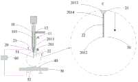
图2是根据本发明实施例的附着液体胶在目标物体的系统的结构示意图。FIG. 2 is a schematic structural diagram of a system for attaching liquid glue to a target object according to an embodiment of the present invention.
图3显示的是根据本发明实施例的附着液体胶在目标物体的系统在使液体胶附着于目标物体时,液体胶形成射向目标物体的胶附着面的射流。FIG. 3 shows a system for attaching liquid glue to a target object according to an embodiment of the present invention. When the liquid glue is attached to the target object, the liquid glue forms a jet directed to the glue attachment surface of the target object.
图4显示的是根据本发明实施例的附着液体胶在目标物体的系统在使液体胶附着于目标物体时,液体胶形成的射流进一步雾化。FIG. 4 shows a system for attaching liquid glue to a target object according to an embodiment of the present invention. When the liquid glue is attached to the target object, the jet formed by the liquid glue is further atomized.
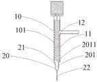
图5A为根据本发明实施例的附着液体胶在目标物体的系统的示例性的胶液供应装置的剖视示意图。5A is a schematic cross-sectional view of an exemplary glue supply device of a system for attaching liquid glue to a target object according to an embodiment of the present invention.
图5B为根据本发明实施例的附着液体胶在目标物体的系统的示例性的胶液供应装置的螺杆的立体示意图。5B is a schematic perspective view of a screw of an exemplary glue supply device of a system for attaching liquid glue to a target object according to an embodiment of the present invention.
图6A显示的是根据本发明实施例的附着液体胶在目标物体的系统的该胶液供应装置的一种可选实施。FIG. 6A shows an optional implementation of the glue supply device of the system for attaching liquid glue to a target object according to an embodiment of the present invention.
图6B显示的是根据本发明实施例的附着液体胶在目标物体的系统的该胶液供应装置的该可选实施的螺杆的立体示意图。FIG. 6B is a schematic perspective view of the optional screw of the glue supply device of the system for attaching liquid glue to a target object according to an embodiment of the present invention.
图7是根据本发明实施例的制备液体胶射流的方法的流程图。7 is a flowchart of a method of preparing a liquid glue jet according to an embodiment of the present invention.
具体实施方式Detailed ways
以下描述被提供以使本领域普通技术人员能够实现本发明。本领域普通技术人员可以想到其它显而易见的替换、修改和变形。因此,本发明所保护范围不应受到本文所描述的示例性的实施方式的限制。The following description is provided to enable those of ordinary skill in the art to practice the invention. Other obvious alternatives, modifications, and variations will occur to those skilled in the art. Accordingly, the scope of the present invention should not be limited by the exemplary embodiments described herein.
本领域普通技术人员应该理解,除非本文中特地指出,术语“一”应理解为“至少一”或“一个或多个”,即在一个实施例中,一个元件的数量可以为一个,而在另外的实施例中,该元件的数量可以为多个。Those of ordinary skill in the art should understand that unless otherwise specified herein, the term "a" should be understood as "at least one" or "one or more", that is, in an embodiment, the number of an element can be one, and in In other embodiments, there may be more than one element.
本领域普通技术人员应该理解,除非本文中特地指出,术语“纵向”、 “横向”、“上”、 “下”、 “前”、 “后”、 “左”、 “右”、 “竖直”、 “水平”、 “顶”、 “底”、 “内”、 “外”等所指代的方位或位置为基于附图所示的方位或位置,仅仅是为了便于描述本发明,而不是指示或暗示所涉及的装置或元件必须具有特定的方位或位置。因此,上述术语不应理解为对本发明的限制。Those of ordinary skill in the art should understand that the terms "longitudinal", "transverse", "upper", "lower", "front", "rear", "left", "right", "vertical ", "horizontal", "top", "bottom", "inner", "outer", etc. refer to the orientation or position based on the orientation or position shown in the drawings, and are only for the convenience of describing the present invention, rather than Indicates or implies that a particular orientation or position is necessary for a device or element in question. Therefore, the above terms should not be construed as limiting the present invention.
参考说明书附图之图2至图5B,根据本发明实施例的附着液体胶在目标物体的系统被阐明。Referring to FIGS. 2 to 5B of the accompanying drawings, a system for attaching liquid glue to a target object according to an embodiment of the present invention is illustrated.
如附图之图2至图5B所示,根据本发明实施例的附着液体胶在目标物体的系统包括胶液供应装置10和喷射器20,其中该胶液供应装置10形成一个胶液供应通道101,该喷射器20形成一个出胶通道201,其中该出胶通道201具有一个进胶口2011和一个出胶口2012,其中该出胶通道201通过该进胶口2011与该胶液供应通道101相连通,以使该液体胶30能够依次通过该胶液供应通道101、该出胶通道201流向该出胶口2012。进一步地,该胶液供应通道101沿一第一预设方向延伸(见图3和图4中箭头A所指方向),该出胶通道201沿一第二预设方向(见图3和图4中箭头B所指方向)自该进胶口2011延伸至该出胶口2012。相应地,该液体胶30可沿该第一预设方向流向该出胶通道201,并沿该第二预设方向流向该出胶口2012和自该出胶通道201的该出胶口2012流出,以附着在该目标物体40的胶附着面401。如附图之图2至图5B所示,优选地,该目标物体40的该胶附着面401被设置朝向该出胶通道201的该出胶口2012,以使自该出胶通道201的该出胶口2012流出的(液体胶)流体301可流向该目标物体40的胶附着面401,从而使液体胶能够附着在该目标物体40的胶附着面401。更优选地,该目标物体40的该胶附着面401与该第二预设方向之间的角度为15度-165度,从而使自该出胶口2012流出的该液体胶30能够流向和附着在该目标物体40的该胶附着面401。优选地,该第一预设方向和该第二预设方向的方向相同。可选地,该第一预设方向和该第二预设方向的方向不同。As shown in Figures 2 to 5B of the accompanying drawings, a system for attaching liquid glue to a target object according to an embodiment of the present invention includes a
如附图之图2至图5B所示,根据本发明实施例的附着液体胶在目标物体的系统的该喷射器20的该出胶通道201具有一个储液部2013和一个喷液部2014,其中该储液部2013形成该进胶口2011,该喷液部2014形成该出胶口2012。优选地,该储液部2013的内径大于该喷液部2014的内径。如附图之图2至图5B所示,根据本发明实施例的附着液体胶在目标物体的系统的该喷射器20包括一个储液管21和一个喷针22,其中该储液管21形成该出胶通道201的该储液部2013,该喷针22形成该出胶通道201的该喷液部2014。相应地,该储液管21的出液端形成一喷嘴。更优选地,该出胶通道201的该出胶口2012为锥形,其顶部(锥的较小一端)朝向该目标物体40。As shown in Figures 2 to 5B of the accompanying drawings, the
如附图之图2至图5B所示,根据本发明实施例的附着液体胶在目标物体的系统进一步具有一个电压源60,其中该电压源60的正极端与一正极51相电连接,其中该正极51被设置在该出胶通道201的该出胶口2012处,以施加一预设电压在自该出胶口2012流出的该液体胶30形成的该流体301,从而使该流体301在该预设电压的作用下形成一射流3011。换句话说,该预设电压被设置能够使自该出胶通道201的该出胶口2012的该流体301形成一个向该目标物体40的该胶附着面401射出的射流3011。优选地,该正极51形成该出胶通道201的该出胶口2012。相应地,该喷射器20的该喷针22形成该正极51,或者该正极51被设置在该喷针22。可选地,该正极51被设置在该出胶口2012的内壁,且该正极51围绕该出胶口2012。可选地,该正极51通过电镀的方式附着在该出胶口2012的内壁。可以理解,该预设电压被设置能够使流经该出胶口2012的该流体301的胶液的电荷极化。相应地,由于电流体力学的作用,自该出胶通道201的该出胶口2012的该流体301的胶液在其重力、表面张力、粘性力和电场力等多种力的共同作用下,形成射向该目标物体40的该胶附着面401的该射流3011。因此,本发明实施例的附着液体胶在目标物体的系统的点胶方式与现有点胶机通过将胶液挤出后附着在目标物体的点胶方式完全不同。如附图之图2至图5B所示,依本发明实施例,自该出胶通道201的该出胶口2012流出的该流体301的胶液在其重力、表面张力、粘性力和该电场力等的共同作用下,尤其是电场力的作用下,形成该射流3011,并使其被“拉”向该目标物体40的该胶附着面401,且该胶液在重力、表面张力、粘性力和该电场力等的共同作用下,被“拉”向该目标物体40的该胶附着面401的过程中,形成的该射流3011的初始外径要明显小于该出胶口2012的内径(仅为该出胶口2012的内径的1/20至1/2,甚至更小)。与传统的点胶方式相比,依本发明实施例的附着液体胶在目标物体的系统提供的点胶胶液在其受到的重力、表面张力、粘性力和该电场力等的共同作用下,在空间的分布更为均匀和不易形成散点。并且,由于该射流3011在刚刚形成时,直径显著小于该出胶口2012的内径,从而使本发明附着液体胶在目标物体的方法能够控制胶线宽度(划线点胶)更小,也更容易实现胶线宽度的精确控制。值得注意的是,由于依本发明实施例的附着液体胶在目标物体的系统通过形成射向该目标物体40的该胶附着面401的该射流3011的方式附着该液体胶30在该目标物体40的该胶附着面401,从而使得该目标物体40的该胶附着面401与该第二预设方向之间的角度在15度-165度范围内,均可较好地附着在该目标物体40的该胶附着面401。因此,与现有的点胶方式相比,本发明实施例的附着液体胶在目标物体的系统的点胶角度范围更大和更容易实现不规则形状物体的点胶。As shown in Figures 2 to 5B of the accompanying drawings, the system for attaching liquid glue to a target object according to an embodiment of the present invention further has a
如附图之图2至图4所示,根据本发明实施例的附着液体胶在目标物体的系统进一步包括至少一个载物台70,其中该目标物体40被承载在该载物台70,其中该载物台70形成一负极52,其中该负极52与该电压源60的负极端相连接。优选地,该载物台70被设置朝向该喷射器20。As shown in Figures 2 to 4 of the accompanying drawings, the system for attaching liquid glue to a target object according to an embodiment of the present invention further includes at least one
值得注意的是,用于粘贴或胶合的流体胶30的粘度一般较大。为了确保该流体胶30在自该出胶口2012喷出时,能够形成稳定的超细射流3011,从而使其能够附着在该目标物体40,该出胶通道201的该出胶口2012距离该目标物体40(或该载物台70)的距离优选为1mm-200mm。这也是本发明附着液体胶在目标物体的系统与现有的点胶系统的显著区别之一:传统的点胶系统,为了点胶精确,尤其是为了避免拖胶和/或拉丝,其出胶口往往距离目标物体较近,大多在1mm之内。而本发明附着液体胶在目标物体的系统根据预设电压的大小和该液体胶30的性质(如粘度),其点胶距离可被控制在1mm-200mm。这更方便操作人员或使用者精确控制点胶。此外,由于本发明附着液体胶在目标物体的系统在点胶时,是通过使该液体胶30形成的该流体301形成的射向该目标物体30的该射流3011射在该目标物体40的方式将该液体胶30附着在该目标物体40上,因此,本发明附着液体胶在目标物体的系统在点胶时,不易发生拖胶和拉丝。优选地,该喷针22远离该储液管21的出液端被磨平,以确保该流体301形成的射向该目标物体30的该射流3011的稳定性和一致性。It should be noted that the viscosity of the
如附图之图4所示,根据本发明实施例的附着液体胶在目标物体的系统还可实现雾化点胶。如附图之图4所示,当该液体胶30的该流体301形成的该射流3011朝向该目标物体40射出足够远的距离时,该射流3011可被雾化和形成喷雾3012。相应地,控制该出胶通道201的该出胶口2012与该目标物体40的该胶附着面401之间的距离,即可控制该液体胶30的点胶方式为非接触式的射流(划线)点胶或喷雾点胶。此外,由于电流体动力学作用,不管是利用该液体胶30在该预设电压的作用下形成的该射流3011点胶,还是利用该射流3011形成的喷雾点胶,均不易出现传统的点胶过程中出现的该液体胶30的拉丝(该液体胶30在点胶过程中形成的难以控制的丝状)现象。当然,当该出胶通道201的该出胶口2012处未施加该预设电压时,本发明附着液体胶在目标物体的系统还可以实现传统的接触式点胶。最后,为了改善该液体胶30的爬胶影响该射流3011的稳定性,可对该喷射器20的该出胶口2012的外壁进行表面处理。如该液体胶30为水性胶,则可对该喷射器20的出胶口2012的外壁进行疏水化处理。或者,该液体胶30为疏水性胶,则可对该喷射器20的出胶口2012的外壁进行亲水化处理。As shown in FIG. 4 of the accompanying drawings, the system for attaching liquid glue to a target object according to an embodiment of the present invention can also realize atomized glue dispensing. As shown in FIG. 4 of the accompanying drawings, when the
如附图之图2至图5B所示,根据本发明实施例的附着液体胶在目标物体的系统的该胶液供应装置10被设置能够定量向该出胶通道201输送该液体胶30,以确保本发明附着液体胶在目标物体的系统能够高精度点胶。如附图之图2至图5B所示,根据本发明实施例的附着液体胶在目标物体的系统的该胶液供应装置10包括一个阀体11、一个螺杆12和一个电机13,其中该阀杆12被可转动地设置在该阀体11的阀腔110内,该电机13被设置用于驱动该螺杆12转动,其中该螺杆12形成该胶液供应通道101,且该胶液供应通道101呈螺旋形围绕该螺杆12,从而使该液体胶30能够随该螺杆12的转动向前移动和被输送向该出胶通道201。相应地,该胶液供应装置10为螺杆阀(或螺杆泵)。然而,该目标物体40可能具有多个胶附着面401,且不同胶附着面401所要点胶的胶线宽度、胶液用量等也可能不同。因此,该目标物体40可被设置有至少一个标记402,其中本发明附着液体胶在目标物体的系统能够根据该标记402控制该液体胶30的定量供应,以确保点胶的精度控制。该目标物体40的该标记402可是数字、图案、图形或其结合。该目标物体40的该标记402也可以是其它任何能标识胶液用量信息的信号。本发明附着液体胶在目标物体的系统可通过传感器识别该标记402,并通过控制单元控制该液体胶30的定量供应和传输。As shown in Figures 2 to 5B of the accompanying drawings, the
如附图之图2至图5B所示,根据本发明实施例的附着液体胶在目标物体的系统可通过加压装置向该胶液供应通道101或该出胶通道201内的该液体胶30施加一个适当压力,以使该液体胶30能够自该出胶通道201的该出胶口2012流出。相应地,该压力的矢量方向与该第一预设方向或该第二预设方向相同,以使该液体胶30能够自该出胶通道201的该出胶口2012流出。可选地,该加压装置为气缸。As shown in Figures 2 to 5B of the accompanying drawings, the system for attaching liquid glue to a target object according to an embodiment of the present invention can supply the
附图之图6A和图6B显示的是根据本发明实施例的附着液体胶在目标物体的系统的该胶液供应装置10的一种可选实施,其中该胶液供应装置10A包括至少两个阀体11A、至少两个螺杆12A、至少两个电机13A和一个基座14A,其中该阀体11A分别设置在该基座14A,该螺杆12A分别可转动地设置在该阀体11A的阀腔110A内,该电机13A被设置用于分别驱动该螺杆12A转动,其中每个该螺杆12A形成一个胶液供应通道101A,该基座14A形成至少两个导通通道1401A和一个混液腔1402A,其中该胶液供应通道101A呈螺旋形围绕相应的该螺杆12A,该导通通道1401A分别与相应的该胶液供应通道101A和该混液腔1402A相连通,该混液腔1402A分别与相应的该导通通道1401A和该出胶通道201相连通。相应地,当该螺杆12A转动时,该液体胶30能够随该螺杆12A的转动向前移动和被输送向该混液腔1402A,该液体胶30在该液体胶30混合后,进一步通过该混液腔1402A被输送至该出胶通道201。可以理解,当该胶液供应装置10A的不同液体胶可通过相应的该胶液供应通道101A、该导通通道1401A沿不同的方向分别被输送至该混液腔1402A,和在该混液腔1402A混合后,进一步输送至该出胶通道201。可以理解,该胶液供应通道101A被相互隔开,该导通通道1401A被相互隔开。多组分液态胶在点胶前需要先混合,然后尽快点胶。当使用现有的点胶方法,通过雾化阀对其雾化时,混合后的多组分液体胶很容易在雾化阀提前固化。本发明实施例的附着液体胶在目标物体的系统通过利用双螺杆阀(或多螺杆阀)结合射流(划线)点胶的方式,解决了传统点胶难以实现双组分胶(或多组分胶)喷雾点胶的难题。优选地,该混液腔1402A沿一第一预设方向(见图6A中箭头A所指方向)延伸在该基座14A。6A and 6B of the accompanying drawings show an optional implementation of the
如下所述,本发明进一步提供以下示例,以示例性地说明本发明附着液体胶在目标物体的方法和系统在点胶应用中的技术优势。下述示例所公开的试验数据,包括各液体胶形成的射流直径、各液体胶形成的射流的雾化高度、各液体胶形成的射流的在各个高度下点胶时,其胶线宽度(划线点胶)或雾面直径(雾化点胶)可能因试验环境、试验设备、电压稳定性、检测仪器的精密程度、系统误差而有所差异,但不影响本发明附着液体胶在目标物体的方法和系统的原理和不应影响本发明的保护范围。As described below, the present invention further provides the following examples to illustrate the technical advantages of the method and system for attaching liquid glue to a target object of the present invention in dispensing applications. The test data disclosed in the following example includes the jet flow diameter formed by each liquid glue, the atomization height of the jet flow formed by each liquid glue, the jet flow formed by each liquid glue when dispensing glue at each height, its glue line width (mark Line dispensing) or fog surface diameter (atomization dispensing) may vary due to the test environment, test equipment, voltage stability, precision of the detection instrument, and system error, but it does not affect the adhesion of the liquid glue on the target object of the present invention. The principles and principles of the method and system should not affect the protection scope of the present invention.
本文中的工作物质指的是液体胶含有的起粘接作用的成分,其可能是一种化合物,也可能是多种化合物的组合。如上述丙烯酸树脂液体胶,其含有的起粘接作用的成分是丙烯酸树脂。本文中的胶线宽度指的是液体胶附着在目标物体后,所形成的胶线的宽度。本文中的雾化高度指的是液体胶形成的射流开始雾化(射流直径大于出胶口直径的3倍)时,该射流射出的距离(自出胶口开始计算)。本文中的雾面直径指的是射流雾化时,其形成的液体胶的胶雾的直径大小。The working substance in this article refers to the adhesive component contained in the liquid glue, which may be a compound or a combination of multiple compounds. As above-mentioned acrylic resin liquid glue, the composition that it contains and plays a bonding role is acrylic resin. The glue line width in this article refers to the width of the glue line formed after the liquid glue is attached to the target object. The atomization height in this article refers to the distance (calculated from the glue outlet) when the jet formed by the liquid glue starts to atomize (the diameter of the jet is greater than 3 times the diameter of the glue outlet). The diameter of the mist surface in this article refers to the diameter of the mist of the liquid glue formed when the jet is atomized.
示例1:液态水的射流形成和射流雾化Example 1: Jet Formation and Jet Atomization of Liquid Water
本示例使用本发明附着液体胶在目标物体的系统实现点胶实验(其胶液供应装置为胶液供应装置10)。首先,常温下,向液态水(其粘度为1cps)施加适当压力,以使其流向该出胶通道201和自该出胶口流出,其中该喷针22的内径为0.1mm,该预设电压为1000V,该液态水形成的射流的直径(距离出胶口1mm处)为0.03mm,该液态水形成的射流的雾化高度为40mm。当该目标物体40距离出胶口的距离为3mm时,其形成的胶线宽度最小为1mm;当该目标物体40距离出胶口的距离为10mm时,其形成的胶线宽度出胶口最小为1.6mm。In this example, the system for attaching liquid glue to a target object of the present invention is used to implement a glue dispensing experiment (the glue supply device is the glue supply device 10 ). First, at normal temperature, apply appropriate pressure to liquid water (its viscosity is 1cps), so that it flows to the
示例2:液态水的射流形成和射流雾化Example 2: Jet Formation and Jet Atomization of Liquid Water
本示例使用本发明附着液体胶在目标物体的系统实现点胶实验(其胶液供应装置为胶液供应装置10)。首先,常温下,向液态水(其粘度为1cps)施加适当压力,以使其流向该出胶通道201和自该出胶口流出,其中该喷针22的内径为0.1mm,该预设电压为3000V,该液态水形成的射流的直径(距离出胶口1mm处)为0.03mm,该液态水形成的射流的雾化高度为25mm。当该目标物体40距离出胶口的距离为5mm时,其形成的胶线宽度最小为0.8mm;当该目标物体40距离出胶口的距离为10mm时,其形成的胶线宽度最小为1.5mm;当该目标物体40距离出胶口的距离为50mm时,其形成的雾化的雾面直径为35mm。In this example, the system for attaching liquid glue to a target object of the present invention is used to implement a glue dispensing experiment (the glue supply device is the glue supply device 10 ). First, at normal temperature, apply appropriate pressure to liquid water (its viscosity is 1cps), so that it flows to the
示例3:液态水的射流形成和射流雾化Example 3: Jet Formation and Jet Atomization of Liquid Water
本示例使用本发明附着液体胶在目标物体的系统实现点胶实验(其胶液供应装置为胶液供应装置10)。首先,常温下,向液态水(其粘度为1cps)施加适当压力,以使其流向该出胶通道201和自该出胶口流出,其中该喷针22的内径为0.1mm,该预设电压为7500V,该液态水形成的射流的直径(距离出胶口1mm处)为0.03mm,该液态水形成的射流的雾化高度为25mm。当该目标物体40距离出胶口的距离为5mm时,其形成的胶线宽度最小为0.7mm;当该目标物体40距离出胶口的距离为10mm时,其形成的胶线宽度最小为1.3mm;当该目标物体40距离出胶口的距离为50mm时,其形成的雾化的雾面直径为40mm。In this example, the system for attaching liquid glue to a target object of the present invention is used to implement a glue dispensing experiment (the glue supply device is the glue supply device 10 ). First, at normal temperature, apply appropriate pressure to liquid water (its viscosity is 1cps), so that it flows to the
示例4:环氧树脂液态胶的射流形成和射流雾化Example 4: Jet Formation and Jet Atomization of Epoxy Liquid Adhesives
本示例使用本发明附着液体胶在目标物体的系统实现点胶实验(其胶液供应装置为胶液供应装置10)。首先,常温下,向环氧树脂液态胶(其粘度为100cps,工作物质为环氧树脂)施加适当压力,以使其流向该出胶通道201和自该出胶口流出,其中该喷针22的内径为0.15mm,该预设电压为1000V,该环氧树脂液态胶形成的射流的直径(距离出胶口1mm处)为0.035mm,该环氧树脂液态胶形成的射流的雾化高度为45mm。当该目标物体40距离出胶口的距离为5mm时,其形成的胶线宽度最小为0.1mm;当该目标物体40距离出胶口的距离为10mm时,其形成的胶线宽度最小为0.55mm;当该目标物体40距离出胶口的距离为100mm时,其形成的雾化的雾面直径为90mm。In this example, the system for attaching liquid glue to a target object of the present invention is used to implement a glue dispensing experiment (the glue supply device is the glue supply device 10 ). First, at normal temperature, apply proper pressure to the epoxy resin liquid glue (its viscosity is 100cps, and the working substance is epoxy resin), so that it flows to the
示例5:环氧树脂液态胶的射流形成和射流雾化Example 5: Jet Formation and Jet Atomization of Epoxy Liquid Adhesives
本示例使用本发明附着液体胶在目标物体的系统实现点胶实验(其胶液供应装置为胶液供应装置10)。首先,常温下,向环氧树脂液态胶(其粘度为100cps,工作物质为环氧树脂)施加适当压力,以使其流向该出胶通道201和自该出胶口流出,其中该喷针22的内径为0.15mm,该预设电压为3000V,该环氧树脂液态胶形成的射流的直径(距离出胶口1mm处)为0.02mm,该环氧树脂液态胶形成的射流的雾化高度为40mm。当该目标物体40距离出胶口的距离为5mm时,其形成的胶线宽度最小为0.03mm;当该目标物体40距离出胶口的距离为10mm时,其形成的胶线宽度最小为0.04mm;当该目标物体40距离出胶口的距离为150mm时,其形成的雾化的雾面直径为110mm。In this example, the system for attaching liquid glue to a target object of the present invention is used to implement a glue dispensing experiment (the glue supply device is the glue supply device 10 ). First, at normal temperature, apply proper pressure to the epoxy resin liquid glue (its viscosity is 100cps, and the working substance is epoxy resin), so that it flows to the
示例6:环氧树脂液态胶的射流雾化Example 6: Jet Atomization of Epoxy Liquid Adhesive
本示例使用本发明附着液体胶在目标物体的系统实现点胶实验(其胶液供应装置为胶液供应装置10)。首先,常温下,向环氧树脂液态胶(其粘度为100cps,工作物质为环氧树脂)施加适当压力,以使其流向该出胶通道201和自该出胶口流出,其中该喷针22的内径为0.15mm,该预设电压为5000V,当该目标物体40距离出胶口的距离为100mm时,环氧树脂液态胶形成的射流的雾化的雾面直径为70mm。In this example, the system for attaching liquid glue to a target object of the present invention is used to implement a glue dispensing experiment (the glue supply device is the glue supply device 10 ). First, at normal temperature, apply proper pressure to the epoxy resin liquid glue (its viscosity is 100cps, and the working substance is epoxy resin), so that it flows to the
示例7:聚氨酯树脂湿气固化(液态)胶的射流形成Example 7: Jet formation of a polyurethane resin moisture-curing (liquid) adhesive
本示例使用本发明附着液体胶在目标物体的系统实现点胶实验(其胶液供应装置为胶液供应装置10)。首先,常温下,向聚氨酯树脂液态胶(其粘度为50cps,工作物质为聚氨酯树脂)施加适当压力,以使其流向该出胶通道201和自该出胶口流出,其中该喷针22的内径为0.075mm,该预设电压为500V,该聚氨酯树脂液态胶形成的射流的直径(距离出胶口1mm处)为0.02mm。当该目标物体40距离出胶口的距离为3mm时,其形成的胶线宽度最小为0.02mm;当该目标物体40距离出胶口的距离为10mm时,其形成的胶线宽度出胶口最小为0.25mm。In this example, the system for attaching liquid glue to a target object of the present invention is used to implement a glue dispensing experiment (the glue supply device is the glue supply device 10 ). First, under normal temperature, apply proper pressure to the polyurethane resin liquid glue (its viscosity is 50cps, and the working substance is polyurethane resin), so that it flows to the
示例8:聚氨酯树脂湿气固化(液态)胶的射流形成和射流雾化Example 8: Jet Formation and Jet Atomization of Urethane Resin Moisture Curing (Liquid) Adhesives
本示例使用本发明附着液体胶在目标物体的系统实现点胶实验(其胶液供应装置为胶液供应装置10)。首先,常温下,向聚氨酯树脂液态胶(其粘度为50cps,工作物质为聚氨酯树脂)施加适当压力,以使其流向该出胶通道201和自该出胶口流出,其中该喷针22的内径为0.075mm,该预设电压为3000V,该聚氨酯树脂液态胶形成的射流的直径(距离出胶口1mm处)为0.02mm,该聚氨酯树脂液态胶形成的射流的雾化高度为35mm。当该目标物体40距离出胶口的距离为5mm时,其形成的胶线宽度最小为0.025mm;当该目标物体40距离出胶口的距离为10mm时,其形成的胶线宽度最小为0.03mm;当该目标物体40距离出胶口的距离为50mm时,其形成的雾化的雾面直径为45mm。In this example, the system for attaching liquid glue to a target object of the present invention is used to implement a glue dispensing experiment (the glue supply device is the glue supply device 10 ). First, under normal temperature, apply proper pressure to the polyurethane resin liquid glue (its viscosity is 50cps, and the working substance is polyurethane resin), so that it flows to the
值得注意的是,本发明附着液体胶在目标物体的方法和系统还解决了现有点胶方法无法实现聚氨酯树脂湿气固化(液态)胶无法雾化点胶的难题。聚氨酯树脂液态胶为湿气固化胶,当使用现有的点胶方法,通过雾化阀对其雾化时,聚氨酯树脂液态胶很容易吸收雾化阀提供的空气中的湿气,导致聚氨酯树脂液态胶提前固化。It is worth noting that the method and system for attaching liquid glue to the target object of the present invention also solves the problem that the existing glue dispensing method cannot realize the polyurethane resin moisture-cured (liquid) glue and cannot atomize the glue. Polyurethane resin liquid glue is a moisture-curing glue. When the existing dispensing method is used to atomize it through the atomizing valve, the polyurethane resin liquid glue can easily absorb the moisture in the air provided by the atomizing valve, resulting in polyurethane resin Liquid glue cures ahead of time.
示例9:聚氨酯树脂液态胶的射流形成和射流雾化Example 9: Jet Formation and Jet Atomization of Polyurethane Resin Liquid Adhesive
本示例使用本发明附着液体胶在目标物体的系统实现点胶实验(其胶液供应装置为胶液供应装置10)。首先,常温下,向聚氨酯树脂液态胶(其粘度为50cps,工作物质为聚氨酯树脂)施加适当压力,以使其流向该出胶通道201和自该出胶口流出,其中该喷针22的内径为0.075mm,该预设电压为7500V,该聚氨酯树脂液态胶形成的射流的直径(距离出胶口1mm处)为0.02mm,该聚氨酯树脂液态胶形成的射流的雾化高度为30mm。当该目标物体40距离出胶口的距离为5mm时,其形成的胶线宽度最小为0.02mm;当该目标物体40距离出胶口的距离为10mm时,其形成的胶线宽度最小为0.022mm;当该目标物体40距离出胶口的距离为50mm时,其形成的雾化的雾面直径为60mm。In this example, the system for attaching liquid glue to a target object of the present invention is used to implement a glue dispensing experiment (the glue supply device is the glue supply device 10 ). First, under normal temperature, apply proper pressure to the polyurethane resin liquid glue (its viscosity is 50cps, and the working substance is polyurethane resin), so that it flows to the
值得注意的是,本发明附着液体胶在目标物体的方法和系统还解决了现有点胶方法无法实现聚氨酯树脂液体胶无法雾化点胶的难题。聚氨酯树脂液态胶为湿气固化胶,当使用现有的点胶方法,通过雾化阀对其雾化时,聚氨酯树脂液态胶很容易吸收雾化阀提供的空气中的湿气,导致聚氨酯树脂液态胶提前固化。It is worth noting that the method and system for attaching liquid glue to the target object of the present invention also solves the problem that the existing glue dispensing method cannot achieve atomized dispensing of polyurethane resin liquid glue. Polyurethane resin liquid glue is a moisture-curing glue. When the existing dispensing method is used to atomize it through the atomizing valve, the polyurethane resin liquid glue can easily absorb the moisture in the air provided by the atomizing valve, resulting in polyurethane resin Liquid glue cures ahead of time.
示例10:环氧树脂液态胶的射流形成和射流雾化Example 10: Jet Formation and Jet Atomization of Epoxy Liquid Adhesives
本示例使用本发明附着液体胶在目标物体的系统实现点胶实验(其胶液供应装置为胶液供应装置10)。首先,常温下,向环氧树脂液态胶(其粘度为1000cps,工作物质为环氧树脂)施加适当压力,以使其流向该出胶通道201和自该出胶口流出,其中该喷针22的内径为0.15mm,该预设电压为1500V,该环氧树脂液态胶形成的射流的直径(距离出胶口1mm处)为0.035mm,该环氧树脂液态胶形成的射流的雾化高度为55mm。当该目标物体40距离出胶口的距离为5mm时,其形成的胶线宽度最小为0.04mm;当该目标物体40距离出胶口的距离为10mm时,其形成的胶线宽度最小为0.04mm;当该目标物体40距离出胶口的距离为100mm时,其形成的雾化的雾面直径为40mm。In this example, the system for attaching liquid glue to a target object of the present invention is used to implement a glue dispensing experiment (the glue supply device is the glue supply device 10 ). First, at normal temperature, apply appropriate pressure to the epoxy resin liquid glue (its viscosity is 1000cps, and the working substance is epoxy resin), so that it flows to the
示例11:环氧树脂液态胶的射流形成和射流雾化Example 11: Jet Formation and Jet Atomization of Epoxy Liquid Adhesives
本示例使用本发明附着液体胶在目标物体的系统实现点胶实验(其胶液供应装置为胶液供应装置10)。首先,常温下,向环氧树脂液态胶(其粘度为1000cps,工作物质为环氧树脂)施加适当压力,以使其流向该出胶通道201和自该出胶口流出,其中该喷针22的内径为0.15mm,该预设电压为3000V,该环氧树脂液态胶形成的射流的直径(距离出胶口1mm处)为0.035mm,该环氧树脂液态胶形成的射流的雾化高度为45mm。当该目标物体40距离出胶口的距离为5mm时,其形成的胶线宽度最小为0.035mm;当该目标物体40距离出胶口的距离为10mm时,其形成的胶线宽度最小为0.04mm;当该目标物体40距离出胶口的距离为100mm时,其形成的雾化的雾面直径为50mm。In this example, the system for attaching liquid glue to a target object of the present invention is used to implement a glue dispensing experiment (the glue supply device is the glue supply device 10 ). First, at normal temperature, apply appropriate pressure to the epoxy resin liquid glue (its viscosity is 1000cps, and the working substance is epoxy resin), so that it flows to the
示例12:环氧树脂液态胶的射流形成和射流雾化Example 12: Jet Formation and Jet Atomization of Epoxy Liquid Adhesives
本示例使用本发明附着液体胶在目标物体的系统实现点胶实验(其胶液供应装置为胶液供应装置10)。首先,常温下,向环氧树脂液态胶(其粘度为1000cps,工作物质为环氧树脂)施加适当压力,以使其流向该出胶通道201和自该出胶口流出,其中该喷针22的内径为0.15mm,该预设电压为7500V,该环氧树脂液态胶形成的射流的直径(距离出胶口1mm处)为0.03mm,该环氧树脂液态胶形成的射流的雾化高度为40mm。当该目标物体40距离出胶口的距离为5mm时,其形成的胶线宽度最小为0.03mm;当该目标物体40距离出胶口的距离为10mm时,其形成的胶线宽度最小为0.03mm;当该目标物体40距离出胶口的距离为100mm时,其形成的雾化的雾面直径为55mm。In this example, the system for attaching liquid glue to a target object of the present invention is used to implement a glue dispensing experiment (the glue supply device is the glue supply device 10 ). First, at normal temperature, apply appropriate pressure to the epoxy resin liquid glue (its viscosity is 1000cps, and the working substance is epoxy resin), so that it flows to the
示例13:锡膏胶的射流形成Example 13: Jet Formation of Solder Paste Adhesive
本示例使用本发明附着液体胶在目标物体的系统实现点胶实验(其胶液供应装置为胶液供应装置10)。首先,常温下,向稀释后锡膏(液态)胶(其粘度为30000cps,工作物质为锡膏)施加适当压力,以使其流向该出胶通道201和自该出胶口流出,其中该喷针22的内径为0.3mm,该预设电压为5000V(10Hz直流电压,方波),该锡膏液态胶形成的射流的直径(距离出胶口1mm处)为0.085mm,当该目标物体40距离出胶口的距离为5mm时,锡膏胶的打点点胶形成的锡膏胶点的直径为60um;当该目标物体40距离出胶口的距离为10mm时,锡膏胶的打点点胶形成锡膏胶点的直径为80um。根据多次实验,调整预设电压的大小、施加在锡膏胶的压力和喷针的内径,锡膏胶的打点点胶形成锡膏胶点的最小直径可达到20um(目前有证据证明的现有点胶机打点点胶的胶点的最小直径为80um:https://nswautomation.com/NSW/micro-dispensing-application-solutions/)。In this example, the system for attaching liquid glue to a target object of the present invention is used to implement a glue dispensing experiment (the glue supply device is the glue supply device 10 ). First, at normal temperature, apply appropriate pressure to the diluted solder paste (liquid) glue (its viscosity is 30000cps, and the working substance is solder paste), so that it flows to the
示例14:丙烯酸树脂液态胶的射流形成和射流雾化Example 14: Jet Formation and Jet Atomization of Liquid Acrylic Adhesive
本示例使用本发明附着液体胶在目标物体的系统实现点胶实验(其胶液供应装置为胶液供应装置10)。首先,常温下,向丙烯酸树脂液态胶(其粘度为30000cps,工作物质为丙烯酸树脂)施加适当压力,以使其流向该出胶通道201和自该出胶口流出,其中该喷针22的内径为0.35mm,该预设电压为2000V,该丙烯酸树脂液态胶形成的射流的直径(距离出胶口1mm处)为0.04mm,该丙烯酸树脂液态胶形成的射流的雾化高度为60mm。当该目标物体40距离出胶口的距离为5mm时,其形成的胶线宽度最小为0.05mm;当该目标物体40距离出胶口的距离为10mm时,其形成的胶线宽度最小为0.05mm;当该目标物体40距离出胶口的距离为100mm时,其形成的雾化的雾面直径为45mm。In this example, the system for attaching liquid glue to a target object of the present invention is used to implement a glue dispensing experiment (the glue supply device is the glue supply device 10 ). First, at normal temperature, apply proper pressure to the acrylic resin liquid glue (its viscosity is 30000cps, and the working substance is acrylic resin), so that it flows to the
示例15:丙烯酸树脂液态胶的射流形成和射流雾化Example 15: Jet Formation and Jet Atomization of Liquid Acrylic Adhesive
射流的直径(距离出胶口1mm处)为本示例使用本发明附着液体胶在目标物体的系统实现点胶实验(其胶液供应装置为胶液供应装置10)。首先,常温下,向丙烯酸树脂液态胶(其粘度为30000cps,工作物质为丙烯酸树脂)施加适当压力,以使其流向该出胶通道201和自该出胶口流出,其中该喷针22的内径为0.35mm,该预设电压为7500V,该丙烯酸树脂液态胶形成的射流的直径(距离出胶口1mm处)为0.04mm,该丙烯酸树脂液态胶形成的射流的雾化高度为50mm。当该目标物体40距离出胶口的距离为5mm时,其形成的胶线宽度最小为0.04mm;当该目标物体40距离出胶口的距离为10mm时,其形成的胶线宽度最小为0.045mm;当该目标物体40距离出胶口的距离为100mm时,其形成的雾化的雾面直径为55mm。The diameter of the jet (1mm away from the glue outlet) is the glue dispensing experiment (the glue supply device is the glue supply device 10 ) using the system of the present invention for attaching liquid glue to the target object in this example. First, at normal temperature, apply proper pressure to the acrylic resin liquid glue (its viscosity is 30000cps, and the working substance is acrylic resin), so that it flows to the
示例16:热熔树脂液态胶的射流形成和射流雾化Example 16: Jet Formation and Jet Atomization of Hot Melt Resin Liquid Adhesive
本示例使用本发明附着液体胶在目标物体的系统实现点胶实验(其胶液供应装置为胶液供应装置10)。首先,常温下,向热熔树脂液态胶(其粘度为30000cps,工作物质为热熔树脂)施加适当压力,以使其流向该出胶通道201和自该出胶口流出,其中该喷针22的内径为0.3mm,该预设电压为500V,该热熔树脂液态胶形成的射流的直径(距离出胶口1mm处)为0.25mm,该热熔树脂液态胶形成的射流的雾化高度为25mm。当该目标物体40距离出胶口的距离为5mm时,其形成的胶线宽度最小为0.4mm;当该目标物体40距离出胶口的距离为10mm时,其形成的胶线宽度最小为0.52mm;当该目标物体40距离出胶口的距离为30mm时,其形成的雾化的雾面直径为42mm。可以理解,本文中的热熔树脂包括现有热熔性树脂,包括但不限于醋酸乙烯共聚物(EVA)、聚酰胺(PA)、聚酯(PES)、聚乙烯(LOPE和HDPE)和聚酯酰胺(PEA)。In this example, the system for attaching liquid glue to a target object of the present invention is used to implement a glue dispensing experiment (the glue supply device is the glue supply device 10 ). First, at normal temperature, apply proper pressure to the hot-melt resin liquid glue (its viscosity is 30000cps, and the working substance is hot-melt resin), so that it flows to the
值得注意的是,本发明附着液体胶在目标物体的方法和系统还解决了现有点胶方法无法实现热熔树脂液态胶雾化点胶的难题。热熔树脂液态胶在点胶前需要先热熔,当使用现有的点胶方法,通过雾化阀对其雾化时,雾化阀提供的空气会对其产生冷却效果,很容易导致热熔树脂液态胶提前固化。It is worth noting that the method and system for attaching liquid glue to the target object of the present invention also solves the problem that the existing glue dispensing method cannot realize atomized glue dispensing of hot melt resin liquid glue. Hot-melt resin liquid glue needs to be melted before dispensing. When the existing dispensing method is used to atomize it through the atomizing valve, the air provided by the atomizing valve will have a cooling effect on it, which will easily cause heat The molten resin liquid glue solidifies in advance.
示例17:热熔树脂液态胶的射流形成和射流雾化Example 17: Jet Formation and Jet Atomization of Hot Melt Resin Liquid Adhesive
本示例使用本发明附着液体胶在目标物体的系统实现点胶实验(其胶液供应装置为胶液供应装置10)。首先,常温下,向热熔树脂液态胶(其粘度为30000cps,工作物质为热熔树脂)施加适当压力,以使其流向该出胶通道201和自该出胶口流出,其中该喷针22的内径为0.3mm,该预设电压为4000V,该热熔树脂液态胶形成的射流的直径(距离出胶口1mm处)为0.04mm,该热熔树脂液态胶形成的射流的雾化高度为70mm。当该目标物体40距离出胶口的距离为5mm时,其形成的胶线宽度最小为0.05mm;当该目标物体40距离出胶口的距离为10mm时,其形成的胶线宽度最小为0.05mm;当该目标物体40距离出胶口的距离为100mm时,其形成的雾化的雾面直径为42mm。可以理解,本文中的热熔树脂包括现有热熔性树脂,包括但不限于醋酸乙烯共聚物(EVA)、聚酰胺(PA)、聚酯(PES)、聚乙烯(LOPE和HDPE)和聚酯酰胺(PEA)。In this example, the system for attaching liquid glue to a target object of the present invention is used to implement a glue dispensing experiment (the glue supply device is the glue supply device 10 ). First, at normal temperature, apply proper pressure to the hot-melt resin liquid glue (its viscosity is 30000cps, and the working substance is hot-melt resin), so that it flows to the
值得注意的是,本发明附着液体胶在目标物体的方法和系统还解决了现有点胶方法无法实现热熔树脂液态胶雾化点胶的难题。热熔树脂液态胶在点胶前需要先热熔,当使用现有的点胶方法,通过雾化阀对其雾化时,雾化阀提供的空气会对其产生冷却效果,很容易导致热熔树脂液态胶提前固化。It is worth noting that the method and system for attaching liquid glue to the target object of the present invention also solves the problem that the existing glue dispensing method cannot realize atomized glue dispensing of hot melt resin liquid glue. Hot-melt resin liquid glue needs to be melted before dispensing. When the existing dispensing method is used to atomize it through the atomizing valve, the air provided by the atomizing valve will have a cooling effect on it, which will easily cause heat The molten resin liquid glue solidifies in advance.
示例18:热熔树脂液态胶的射流形成和射流雾化Example 18: Jet Formation and Jet Atomization of Hot Melt Resin Liquid Adhesive
本示例使用本发明附着液体胶在目标物体的系统实现点胶实验(其胶液供应装置为胶液供应装置10)。首先,常温下,向热熔树脂液态胶(其粘度为30000cps,工作物质为热熔树脂)施加压力,以使其流向该出胶通道201和自该出胶口流出,其中该喷针22的内径为0.3mm,该预设电压为7500V,该热熔树脂液态胶形成的射流的直径(距离出胶口1mm处)为0.03mm,该热熔树脂液态胶形成的射流的雾化高度为60mm。当该目标物体40距离出胶口的距离为5mm时,其形成的胶线宽度最小为0.05mm;当该目标物体40距离出胶口的距离为10mm时,其形成的胶线宽度最小为0.05mm;当该目标物体40距离出胶口的距离为100mm时,其形成的雾化的雾面直径为50mm。可以理解,本文中的热熔树脂包括现有热熔性树脂,包括但不限于醋酸乙烯共聚物(EVA)、聚酰胺(PA)、聚酯(PES)、聚乙烯(LOPE和HDPE)和聚酯酰胺(PEA)。In this example, the system for attaching liquid glue to a target object of the present invention is used to implement a glue dispensing experiment (the glue supply device is the glue supply device 10 ). First, at normal temperature, apply pressure to the hot-melt resin liquid glue (its viscosity is 30000cps, and the working substance is hot-melt resin), so that it flows to the
值得注意的是,本发明附着液体胶在目标物体的方法和系统还解决了现有点胶方法无法实现热熔树脂液态胶雾化点胶的难题。热熔树脂液态胶在点胶前需要先热熔,当使用现有的点胶方法,通过雾化阀对其雾化时,雾化阀提供的空气会对其产生冷却效果,很容易导致热熔树脂液态胶提前固化。It is worth noting that the method and system for attaching liquid glue to the target object of the present invention also solves the problem that the existing glue dispensing method cannot realize atomized glue dispensing of hot melt resin liquid glue. Hot-melt resin liquid glue needs to be melted before dispensing. When the existing dispensing method is used to atomize it through the atomizing valve, the air provided by the atomizing valve will have a cooling effect on it, which will easily cause heat The molten resin liquid glue solidifies in advance.
示例19:双组份胶的射流形成和射流雾化Example 19: Jet formation and jet atomization of two-component adhesives
本示例使用本发明附着液体胶在目标物体的系统实现点胶实验(其胶液供应装置为胶液供应装置10)。利用双螺杆系统对双组份胶中的AB组份分别进料,组份比例为1:1,AB组份粘度分别为3000cps和2500cps,AB组份通过螺杆系统进料的流量都为0.002 mL/min,混合后的总流量为0.004mL/min,点胶胶水点胶速度为10mm/s,电压为3000V,点胶高度5mm,点胶宽度为0.1mm。In this example, the system for attaching liquid glue to a target object of the present invention is used to implement a glue dispensing experiment (the glue supply device is the glue supply device 10 ). Use the twin-screw system to feed the AB components in the two-component glue separately, the component ratio is 1:1, the viscosity of the AB components is 3000cps and 2500cps respectively, and the flow rate of the AB components through the screw system is 0.002 mL. /min, the total flow rate after mixing is 0.004mL/min, the dispensing speed of dispensing glue is 10mm/s, the voltage is 3000V, the dispensing height is 5mm, and the dispensing width is 0.1mm.
值得注意的是,本发明附着液体胶在目标物体的方法和系统还解决了现有点胶方法无法实现双组份胶非接触点胶的难题。由于双组份胶需要在点胶前提前混合,混合的过程往往只能在外置流道上进行,因为混合部分容易固化,往往需要定期更换。因此双组份胶无法在非接触式喷胶前进行胶水的混合,导致现有技术无法实现双组份胶水非接触式点胶。It is worth noting that the method and system for attaching liquid glue to the target object of the present invention also solves the problem that the existing glue dispensing method cannot realize non-contact dispensing of two-component glue. Since the two-component adhesive needs to be mixed in advance before dispensing, the mixing process can only be carried out on the external flow channel, because the mixed part is easy to solidify and often needs to be replaced regularly. Therefore, the two-component glue cannot be mixed before the non-contact glue spraying, resulting in the inability to realize the non-contact dispensing of the two-component glue in the prior art.
示例20:双组份胶的射流形成和射流雾化Example 20: Jet formation and jet atomization of two-component adhesives
本示例使用本发明附着液体胶在目标物体的系统实现点胶实验。利用双螺杆系统对双组份胶中的AB组份分别进料,组份比例为10:1,AB组份粘度分别为3000cps和500cps,AB组份通过螺杆系统进料的流量分别为1mL/min和0.1mL,混合后的总流量为1.1mL/min,点胶胶水点胶速度为10mm/s,电压为4000V,点胶高度100mm,雾化直径为70mm。This example uses the system of the present invention for attaching liquid glue to a target object to realize a glue dispensing experiment. Use the twin-screw system to feed the AB components in the two-component glue separately, the component ratio is 10:1, the viscosity of the AB components is 3000cps and 500cps, and the flow rate of the AB components through the screw system is 1mL/ min and 0.1mL, the total flow rate after mixing is 1.1mL/min, the dispensing speed of dispensing glue is 10mm/s, the voltage is 4000V, the dispensing height is 100mm, and the atomization diameter is 70mm.
值得注意的是,本发明附着液体胶在目标物体的方法和系统还解决了现有点胶方法无法实现双组份胶混合后雾化的难题。现有的技术都是利用双头喷雾阀在阀外对胶水进行雾化+混合,由于双组份胶需要在点胶前提前混合,混合的过程往往只能在外置流道上进行,因为混合部分容易固化,往往需要定期更换。因此双组份胶无法在非接触式喷胶前进行胶水的混合,导致现有技术无法实现双组份胶水混合后雾化。It is worth noting that the method and system for attaching liquid glue to the target object of the present invention also solves the problem that the existing glue dispensing method cannot realize the atomization of two-component glue after mixing. The existing technology is to use the double-head spray valve to atomize and mix the glue outside the valve. Since the two-component glue needs to be mixed in advance before dispensing, the mixing process can only be carried out on the external flow channel, because the mixing part Cures easily and tends to require periodic replacement. Therefore, the two-component glue cannot be mixed before the non-contact glue spraying, resulting in the inability of the prior art to realize the atomization of the two-component glue after mixing.
如附图之图1A所示,根据本发明实施例,本发明进一步提供一种附着液体胶在目标物体的方法,其包括下述步骤:As shown in Figure 1A of the accompanying drawings, according to an embodiment of the present invention, the present invention further provides a method for attaching liquid glue to a target object, which includes the following steps:
(A)驱动液体胶沿一第一预设方向流向出胶通道;(A) driving the liquid glue to flow to the glue outlet channel along a first preset direction;
(B)使该液体胶沿一第二预设方向自该出胶通道的出胶口流出,其中该出胶通道的出胶口处被施加一预设电压;和(B) making the liquid glue flow out from the glue outlet of the glue outlet channel along a second preset direction, wherein a preset voltage is applied to the glue outlet of the glue outlet channel; and
(C)使该液体胶附着在目标物体的胶附着面,其中该目标物体的该胶附着面被设置朝向该出胶通道的出胶口。(C) Adhering the liquid glue to the glue-adhering surface of the target object, wherein the glue-attaching surface of the target object is set to face the glue outlet of the glue outlet channel.
如附图之图1A所示,根据本发明实施例,本发明附着液体胶在目标物体的方法进一步包括下述步骤:As shown in Figure 1A of the accompanying drawings, according to an embodiment of the present invention, the method for attaching liquid glue to a target object further includes the following steps:
(X)施加适当压力在该液体胶,以使该液体胶能够沿该第一预设方向流向该出胶通道,其中该步骤(X)位于该步骤(A)之前。优选地,该液体胶被驱动沿一螺旋路径流向该出胶通道。可以理解,该适当压力被设置能够驱动该液体胶自该出胶通道的出胶口流出。(X) applying proper pressure on the liquid glue so that the liquid glue can flow to the glue outlet channel along the first predetermined direction, wherein the step (X) is located before the step (A). Preferably, the liquid glue is driven to flow toward the glue outlet channel along a helical path. It can be understood that the proper pressure is set to drive the liquid glue to flow out from the glue outlet of the glue outlet channel.
根据本发明实施例,如附图之图1A所示的本发明附着液体胶在目标物体的方法进一步包括下述步骤:According to an embodiment of the present invention, the method for attaching liquid glue to a target object of the present invention as shown in FIG. 1A of the accompanying drawings further includes the following steps:
(Y)设置该预设电压,以使自该出胶口流出的该液体胶能够形成一射流,和设置该目标物体与该出胶口之间的距离,以使该射流能够射在该目标物体的该胶附着面,从而使该液体胶能够附着在该目标物体的该胶附着面,其中该步骤(Y)位于该步骤(B)之后,该步骤(C)之前。相应地,当该射流射在该目标物体(的胶附着面)时,该液体胶即被使附着在该目标物体(的胶附着面),此外,该预设电压对该流体胶的电荷极化作用还使该流体胶能够更稳固地附着在该目标物体。(Y) Set the preset voltage so that the liquid glue flowing from the glue outlet can form a jet, and set the distance between the target object and the glue outlet so that the jet can hit the target The glue-attached surface of the object, so that the liquid glue can be attached to the glue-attached surface of the target object, wherein the step (Y) is located after the step (B) and before the step (C). Correspondingly, when the jet hits the target object (the glue-adhering surface), the liquid glue is made to adhere to the target object (the glue-attaching surface), and the preset voltage is extremely charged to the fluid glue. Oxygenation also enables the fluid glue to adhere more firmly to the target object.
根据本发明实施例,如附图之图1A所示的本发明附着液体胶在目标物体的方法进一步包括下述步骤:According to an embodiment of the present invention, the method for attaching liquid glue to a target object of the present invention as shown in FIG. 1A of the accompanying drawings further includes the following steps:
(Z)设置该预设电压,以使自该出胶口流出的该液体胶能够形成一射流,和设置该目标物体与该出胶口之间的距离,以使该射流能够雾化和使雾化后的该射流能够喷射在该目标物体的该胶附着面,该步骤(Z)位于该步骤(B)之后,该步骤(C)之前。相应地,当雾化后的该射流喷射在该目标物体(的胶附着面)时,该液体胶即被使附着在该目标物体(的胶附着面)。此外,该预设电压对该流体胶的电荷极化作用还使该流体胶能够更稳固地附着在该目标物体。(Z) Set the preset voltage so that the liquid glue flowing from the glue outlet can form a jet, and set the distance between the target object and the glue outlet so that the jet can be atomized and made The atomized jet can be sprayed on the adhesive surface of the target object, and the step (Z) is located after the step (B) and before the step (C). Correspondingly, when the atomized jet sprays on (the glue-adhering surface of) the target object, the liquid glue is made to adhere to (the glue-attaching surface of) the target object. In addition, the charge polarization effect of the preset voltage on the fluid glue also enables the fluid glue to be more firmly attached to the target object.
如附图之图1B所示,根据本发明实施例,本发明进一步提供另一种附着液体胶在目标物体的方法,其包括下述步骤:As shown in Figure 1B of the accompanying drawings, according to an embodiment of the present invention, the present invention further provides another method for attaching liquid glue to a target object, which includes the following steps:
(A)在该出胶通道的出胶口处施加一预设电压,和设置该目标物体的胶附着面朝向出胶通道的出胶口;(A) Apply a preset voltage to the glue outlet of the glue outlet, and set the glue attachment surface of the target object to face the glue outlet of the glue outlet;
(B)驱动液体胶沿一第一预设方向流向该出胶通道;(B) driving the liquid glue to flow to the glue outlet channel along a first preset direction;
(C)使该液体胶沿一第二预设方向自该出胶通道的出胶口流出,其中该预设电压被设置能够使自该出胶口流出的该液体胶形成一射流;和(C) causing the liquid glue to flow out from the glue outlet of the glue outlet channel along a second preset direction, wherein the preset voltage is set to enable the liquid glue flowing out of the glue outlet to form a jet; and
(D)使该射流射在该目标物体的胶附着面,从而使该液体胶附着在该目标物体的该胶附着面。此外,该预设电压对该流体胶的电荷极化作用还使该流体胶能够更稳固地附着在该目标物体。(D) making the jet flow on the glue-attached surface of the target object, so that the liquid glue is attached to the glue-attached surface of the target object. In addition, the charge polarization effect of the preset voltage on the fluid glue also enables the fluid glue to be more firmly attached to the target object.
根据本发明实施例,如附图之图1B所示的本发明附着液体胶在目标物体的方法进一步包括下述步骤:According to an embodiment of the present invention, the method for attaching liquid glue to a target object of the present invention as shown in FIG. 1B of the accompanying drawings further includes the following steps:
(W)设置该目标物体与该出胶口之间的距离,以该射流能够射在该目标物体。(W) Set the distance between the target object and the glue outlet so that the jet can hit the target object.
如附图之图1C所示,根据本发明实施例,本发明进一步提供另一种附着液体胶在目标物体的方法,其包括下述步骤:As shown in Figure 1C of the accompanying drawings, according to an embodiment of the present invention, the present invention further provides another method for attaching liquid glue to a target object, which includes the following steps:
(A)在该出胶通道的出胶口处施加一预设电压,和设置该目标物体的胶附着面朝向出胶通道的出胶口;(A) Apply a preset voltage to the glue outlet of the glue outlet, and set the glue attachment surface of the target object to face the glue outlet of the glue outlet;
(B)驱动液体胶沿一第一预设方向流向该出胶通道;(B) driving the liquid glue to flow to the glue outlet channel along a first preset direction;
(C)使该液体胶沿一第二预设方向自该出胶通道的出胶口流出,其中该预设电压被设置能够使自该出胶口流出的该液体胶形成一射流;和(C) causing the liquid glue to flow out from the glue outlet of the glue outlet channel along a second preset direction, wherein the preset voltage is set to enable the liquid glue flowing out of the glue outlet to form a jet; and
(D)设置该目标物体与该出胶口之间的距离,以使该射流能够雾化和使雾化后的该射流喷射在该目标物体。相应地,当雾化后的该射流喷射在该目标物体(的胶附着面)时,该液体胶即被使附着在该目标物体(的胶附着面)。此外,该预设电压对该流体胶的电荷极化作用还使该流体胶能够更稳固地附着在该目标物体。(D) Set the distance between the target object and the glue outlet, so that the jet can be atomized and spray the atomized jet on the target object. Correspondingly, when the atomized jet sprays on (the glue-adhering surface of) the target object, the liquid glue is made to adhere to (the glue-attaching surface of) the target object. In addition, the charge polarization effect of the preset voltage on the fluid glue also enables the fluid glue to be more firmly attached to the target object.
相应地,根据本文公开内容,结合申请人的长时间研究和探索,本发明附着液体胶在目标物体的方法和系统在实现点胶时,液体胶30形成的射流3011的直径为30μm-1000μm。优选地,该射流3011的直径为30μm-100μm。该液体胶30形成的该流体301的直径为50μm-3000μm。优选地,该液体胶30形成的该流体301的直径为75μm-350μm。施加在该流体301的预设电压的大小为该预设电压的大小为500V-7500V。该液体胶的粘度为1cps-30000cps。优选地,该液体胶的粘度为500cps-30000cps。更优选地,该液体胶的粘度为5000cps-30000cps。当本发明附着液体胶在目标物体的方法和系统在实现点胶时,该出胶口与该胶附着面之间的距离优选设置为1mm-200mm。优选地,该出胶口与该胶附着面之间的距离优选设置为5mm-150mm。更具体地,当本发明附着液体胶在目标物体的方法和系统在实现射流(划线)点胶时,该出胶口与该胶附着面之间的距离优选设置为5mm-45mm;当本发明附着液体胶在目标物体的方法和系统在实现雾化点胶时,该出胶口与该胶附着面之间的距离优选设置为20mm-150mm。优选地,该流体胶含有的成分均具有电绝缘性。Correspondingly, according to the disclosure herein, combined with the applicant’s long-term research and exploration, when the method and system for attaching liquid glue to the target object of the present invention realize dispensing, the diameter of the
因此,依本发明实施例,本发明附着液体胶在目标物体的方法和系统尤其解决了利用现有点胶方法对高粘度(5000cps-30000cps)液体胶点胶时,液体胶的拖胶和拉丝现象,和高粘度液体胶难以雾化点胶的难题。Therefore, according to the embodiment of the present invention, the method and system for attaching liquid glue to the target object of the present invention especially solves the problem of dragging and stringing of liquid glue when dispensing high-viscosity (5000cps-30000cps) liquid glue using the existing dispensing method Phenomenon, and the difficulty of atomizing and dispensing high-viscosity liquid glue.
如附图之图7所示,根据本发明实施例,本发明进一步提供另一种制备液体胶射流的方法,其包括下述步骤:As shown in Figure 7 of the accompanying drawings, according to an embodiment of the present invention, the present invention further provides another method for preparing a liquid glue jet, which includes the following steps:
使该液体胶形成一流体;和forming the liquid glue into a fluid; and
施加一预设电压在该流体,以使该流体能够形成一射流,其中该射流的直径为30μm-1000μm。A preset voltage is applied to the fluid so that the fluid can form a jet, wherein the diameter of the jet is 30 μm-1000 μm.
可以理解,本文中第一和/或第二仅用于对本发明的不同部件(或元件)的命名和使本发明的不同部件(或元件)之间产生区分,其本身不具有次序或数目多少的含义。It can be understood that the first and/or second herein are only used to name different parts (or elements) of the present invention and to make distinctions between different parts (or elements) of the present invention, and have no order or number in themselves meaning.
本领域普通技术人员应该理解,上述描述和附图所示的实施方式仅仅是为了示例性地解释本发明,而不是对本发明的限制。所有在本发明精神之内的等同实施、修改和改进均应包含在本发明的保护范围之内。Those skilled in the art should understand that the above description and the implementations shown in the drawings are only for illustrative purposes of explaining the present invention, rather than limiting the present invention. All equivalent implementations, modifications and improvements within the spirit of the present invention shall be included in the protection scope of the present invention.
Claims (10)
Priority Applications (1)
| Application Number | Priority Date | Filing Date | Title |
|---|---|---|---|
| CN202111219210.6ACN115990551A (en) | 2021-10-20 | 2021-10-20 | Method for producing a jet of liquid glue |
Applications Claiming Priority (1)
| Application Number | Priority Date | Filing Date | Title |
|---|---|---|---|
| CN202111219210.6ACN115990551A (en) | 2021-10-20 | 2021-10-20 | Method for producing a jet of liquid glue |
Publications (1)
| Publication Number | Publication Date |
|---|---|
| CN115990551Atrue CN115990551A (en) | 2023-04-21 |
Family
ID=85990785
Family Applications (1)
| Application Number | Title | Priority Date | Filing Date |
|---|---|---|---|
| CN202111219210.6APendingCN115990551A (en) | 2021-10-20 | 2021-10-20 | Method for producing a jet of liquid glue |
Country Status (1)
| Country | Link |
|---|---|
| CN (1) | CN115990551A (en) |
Citations (6)
| Publication number | Priority date | Publication date | Assignee | Title |
|---|---|---|---|---|
| US20010003148A1 (en)* | 1997-07-22 | 2001-06-07 | Coffee Ronald Alan | Dispensing device and method for forming material |
| CN1635933A (en)* | 2002-02-21 | 2005-07-06 | 独立行政法人产业技术综合研究所 | Ultrafine Fluid Jetting Equipment |
| RU2343997C1 (en)* | 2007-06-09 | 2009-01-20 | Научно-исследовательский институт механики Московского государственного университета им. М.В. Ломоносова | Method of metal vessel treatment with electrified spray |
| US20160029475A1 (en)* | 2014-07-22 | 2016-01-28 | Industry-Academic Cooperation Foundation Yonsei University | Flexible transparent electrode and method for manufacturing same |
| CN111655382A (en)* | 2017-11-13 | 2020-09-11 | 奥普托美克公司 | Blockage of aerosol flow |
| CN111823570A (en)* | 2019-04-16 | 2020-10-27 | 株式会社 Enjet | Induced Electrohydrodynamic Jet Printing Device |
- 2021
- 2021-10-20CNCN202111219210.6Apatent/CN115990551A/enactivePending
Patent Citations (6)
| Publication number | Priority date | Publication date | Assignee | Title |
|---|---|---|---|---|
| US20010003148A1 (en)* | 1997-07-22 | 2001-06-07 | Coffee Ronald Alan | Dispensing device and method for forming material |
| CN1635933A (en)* | 2002-02-21 | 2005-07-06 | 独立行政法人产业技术综合研究所 | Ultrafine Fluid Jetting Equipment |
| RU2343997C1 (en)* | 2007-06-09 | 2009-01-20 | Научно-исследовательский институт механики Московского государственного университета им. М.В. Ломоносова | Method of metal vessel treatment with electrified spray |
| US20160029475A1 (en)* | 2014-07-22 | 2016-01-28 | Industry-Academic Cooperation Foundation Yonsei University | Flexible transparent electrode and method for manufacturing same |
| CN111655382A (en)* | 2017-11-13 | 2020-09-11 | 奥普托美克公司 | Blockage of aerosol flow |
| CN111823570A (en)* | 2019-04-16 | 2020-10-27 | 株式会社 Enjet | Induced Electrohydrodynamic Jet Printing Device |
Similar Documents
| Publication | Publication Date | Title |
|---|---|---|
| TWI494168B (en) | Spray device for small amount of liquid | |
| CA2186762A1 (en) | Dispensing device | |
| KR101703383B1 (en) | Application element, device and method for applying a layer of a viscous material onto a substrate | |
| EP0539971A1 (en) | Method and apparatus of dispensing multiple beads of viscous liquid | |
| JP2000501331A (en) | Method and apparatus for dispensing small amounts of liquid material | |
| US20040217202A1 (en) | Airless conformal coating apparatus and method | |
| CN1030032A (en) | Method and apparatus for air-controlled intermittent and continuous spraying of viscous liquids | |
| JP2001500962A (en) | Equipment for dispensing small quantities of material | |
| US20250050370A1 (en) | Spray Head Improvements for an Ultrasonic Spray Coating Assembly | |
| US7934465B1 (en) | Adhesive applicator head | |
| US6368409B1 (en) | Electrostatic dispensing apparatus and method | |
| CN218423767U (en) | System for adhering liquid glue to target object and glue dispensing assembly | |
| JP2021141003A (en) | Rechargeable battery manufacturing method or rechargeable battery | |
| CN115990551A (en) | Method for producing a jet of liquid glue | |
| US5290600A (en) | Apparatus and process for producing sheets of material | |
| CN115990563A (en) | Method and system for attaching liquid glue to a target object | |
| CN108580169A (en) | Roller coating dispenser | |
| KR102254361B1 (en) | Spray valve for low flow late to coat a medium- and high-levels viscosity liquid material | |
| CN217450595U (en) | Pneumatic dispensing assembly | |
| CN217450596U (en) | System for adhering liquid glue to target object and glue dispensing assembly | |
| CN115970138A (en) | Nasal cavity drug delivery device | |
| CN215612802U (en) | Spiral gluing nozzle | |
| CN116020694A (en) | Glue layer thickness control device in rubberizing process | |
| CN107921461A (en) | To the applying device and coating method of curved surface base material coating liquid coating | |
| TWI792883B (en) | Fluid control structure of dispensing apparatus |
Legal Events
| Date | Code | Title | Description |
|---|---|---|---|
| PB01 | Publication | ||
| PB01 | Publication | ||
| SE01 | Entry into force of request for substantive examination | ||
| SE01 | Entry into force of request for substantive examination |