CN115990312A - Perfusion balloon catheter - Google Patents
Perfusion balloon catheterDownload PDFInfo
- Publication number
- CN115990312A CN115990312ACN202310160973.0ACN202310160973ACN115990312ACN 115990312 ACN115990312 ACN 115990312ACN 202310160973 ACN202310160973 ACN 202310160973ACN 115990312 ACN115990312 ACN 115990312A
- Authority
- CN
- China
- Prior art keywords
- balloon
- perfusion
- catheter
- drug
- catheter assembly
- Prior art date
- Legal status (The legal status is an assumption and is not a legal conclusion. Google has not performed a legal analysis and makes no representation as to the accuracy of the status listed.)
- Pending
Links
Images


Landscapes
- Media Introduction/Drainage Providing Device (AREA)
Abstract
Translated fromChinese
Description
Translated fromChinese技术领域technical field
本发明涉及医疗器械技术领域,特别涉及一种灌注球囊导管。The invention relates to the technical field of medical devices, in particular to a perfusion balloon catheter.
背景技术Background technique
血管疾病已经成为我国第一大致死性疾病,而血管疾病中血管栓塞或其他病变已成为主要因素。Vascular disease has become the number one fatal disease in my country, and vascular embolism or other lesions have become the main factors in vascular disease.
目前的溶栓治疗方案中,全身抗凝治疗仅能阻止血栓的滋长,蔓延和预防肺栓塞及血栓再发生,但是不能溶解血栓和清除静脉瓣膜上的血栓物质,不能预防体栓塞后遗症。但是现有置管溶栓方案中灌注导管常采用造影导管等代替,造影导管上灌注孔为圆柱孔且直径较大,造成药量不易控制。也有些灌注导管的管身上具有通过其他方式制作的孔洞,可以更好地控制药量。但是发明人发现现有的灌注方式都是将药物灌注到血管内,但药物无法直接作用于血栓,造成药物浓度达不到要求,从而不必要地延长了溶栓时间以及药物量的增加。In the current thrombolytic treatment plan, systemic anticoagulant therapy can only prevent the growth of thrombus, spread and prevent pulmonary embolism and recurrence of thrombus, but cannot dissolve thrombus and remove thrombus material on venous valves, and cannot prevent sequelae of embolism. However, in the existing catheter-placed thrombolysis scheme, the perfusion catheter is often replaced by a contrast catheter. The perfusion hole on the contrast catheter is a cylindrical hole with a large diameter, which makes it difficult to control the drug dose. There are also irrigation catheters that have holes made in the body of the tube by other means to better control the dose of the drug. However, the inventors found that the existing perfusion methods are to infuse drugs into the blood vessels, but the drugs cannot directly act on the thrombus, causing the drug concentration to fail to meet the requirements, thereby unnecessarily prolonging the thrombolysis time and increasing the amount of drugs.
发明内容Contents of the invention
本发明实施例的目的在于提供一种灌注球囊导管,通过膨胀挤压在病变处表面的球囊向病变处施药,使得药物可以直接作用于病变处,有利于病变处持续保持足够的药物浓度,从而可提高治疗效率,减少药物量,并且可同时快速开通血路,减轻病症。The purpose of the embodiment of the present invention is to provide a perfusion balloon catheter, which can apply medicine to the lesion by inflating and squeezing the balloon on the surface of the lesion, so that the medicine can directly act on the lesion, which is conducive to continuously maintaining sufficient medicine in the lesion Concentration, so as to improve treatment efficiency, reduce the amount of drugs, and at the same time, quickly open the blood channel and relieve symptoms.
为解决上述技术问题,本发明实施例提供了一种灌注球囊导管,包括:注药球囊以及导管组件;In order to solve the above technical problems, an embodiment of the present invention provides a perfusion balloon catheter, including: a drug injection balloon and a catheter assembly;
所述注药球囊设置于所述导管组件远端且环绕所述导管组件设置;所述注药球囊能够径向膨胀和收缩且其膨胀时具有围绕所述导管组件的灌注囊腔以及轴向贯通的血流通道;The drug injection balloon is disposed at the distal end of the catheter assembly and is arranged around the catheter assembly; the drug injection balloon is radially expandable and contractible and has a perfusion sac around the catheter assembly and a shaft when inflated. To the through blood flow channel;
所述导管组件与所述灌注囊腔连通并用于向所述灌注囊腔输注药液同时还使所述注药球囊膨胀;The catheter assembly communicates with the perfusion sac and is used to infuse the drug solution into the perfusion sac while also inflating the drug injection balloon;
所述注药球囊外周壁布设有与所述灌注囊腔连通的多个灌注结构。A plurality of perfusion structures communicated with the perfusion cavity are arranged on the peripheral wall of the injection balloon.
作为一个实施例,所述血流通道与所述导管组件偏心设置;As an embodiment, the blood flow channel and the catheter assembly are arranged eccentrically;
可选地,所述血流通道截面呈圆形或者椭圆形;Optionally, the cross-section of the blood flow channel is circular or elliptical;
或者or
所述血流通道与所述导管组件同心设置。The blood flow channel is concentrically disposed with the catheter assembly.
作为一个实施例,所述注药球囊包括内层和外层;As an embodiment, the injection balloon includes an inner layer and an outer layer;
所述内层和外层粘接或者焊接形成所述注药球囊;The inner layer and the outer layer are bonded or welded to form the injection balloon;
或者or
所述注药球囊为一体成型结构。The injection balloon is an integrally formed structure.
作为一个实施例,所述灌注结构为灌注孔或者灌注缝。As an embodiment, the perfusion structure is a perfusion hole or perfusion slit.
作为一个实施例,所述灌注孔呈圆形或者椭圆形;As an embodiment, the perfusion hole is circular or oval;
可选地,所述灌注结构均匀分布于所述注药球囊外周壁。Optionally, the perfusion structure is evenly distributed on the peripheral wall of the drug injection balloon.
作为一个实施例,所述导管组件包括:从近端到远端依次相连的管座、导管管体以及导管头端;As an embodiment, the catheter assembly includes: a tube base, a catheter body, and a catheter head connected in sequence from the proximal end to the distal end;
所述导管头端凸伸出所述注药球囊远端;The tip of the catheter protrudes from the distal end of the injection balloon;
所述管座以及所述导管管体内壁设置有与所述灌注囊腔连通的输送通道;The tube base and the inner wall of the catheter tube are provided with a delivery channel communicating with the perfusion sac;
所述管座上还设有与所述输送通道连通的灌注接头;The base is also provided with a perfusion joint that communicates with the delivery channel;
可选地,所述输送通道与所述灌注囊腔之间通过沿所述导管管体轴向延伸的开口连通;Optionally, the delivery channel communicates with the perfusion sac through an opening extending axially along the catheter body;
可选地,所述注药球囊与所述导管管体焊接或者粘接。Optionally, the injection balloon is welded or bonded to the catheter body.
作为一个实施例,所述导管组件还设有导丝腔,所述导丝腔与所述输送通道隔绝;As an embodiment, the catheter assembly is also provided with a guide wire cavity, and the guide wire cavity is isolated from the delivery channel;
可选地,所述管座上还设有凸伸出所述管座近端的导丝穿入口。Optionally, the tube base is also provided with a guide wire insertion port protruding from the proximal end of the tube base.
作为一个实施例,所述灌注球囊导管还包括至少一显影环;As an embodiment, the perfusion balloon catheter further includes at least one imaging ring;
所述至少一显影环设置于所述导管管体上。The at least one developing ring is disposed on the catheter body.
作为一个实施例,所述显影环为两个,且分别设置于所述注药球囊两端的导管管体上;As an embodiment, there are two developing rings, which are respectively arranged on the catheter tubes at both ends of the drug injection balloon;
可选地,所述注药球囊远端和/或近端具有过渡连接至所述管体的肩部;所述显影环设置于所述肩部对应的导管管体上。Optionally, the distal end and/or the proximal end of the injection balloon has a shoulder transitionally connected to the tubular body; the imaging ring is disposed on the catheter tubular body corresponding to the shoulder.
作为一个实施例,所述灌注囊腔为一体连通的囊腔;或者;As an embodiment, the perfusion cavity is a connected cavity; or;
所述灌注囊腔分为若干个周向相隔绝的子腔,且所述导管组件用于分别向各个子腔输注药液。The perfusion sac cavity is divided into several circumferentially isolated sub-cavities, and the catheter assembly is used to infuse medical fluid into each sub-cavity respectively.
由上述技术方案可知,本发明至少具有如下优点和积极效果:As can be seen from the foregoing technical solutions, the present invention at least has the following advantages and positive effects:
本发明实施例的灌注球囊导管中,注药球囊设置于导管组件远端并环绕导管组件设置,且注药球囊径向膨胀时具有围绕导管组件的灌注囊腔以及轴向贯通的血流通道,通过导管组件向灌注囊腔输注药液可使注药球囊膨胀并挤压在病变处,通过注药球囊上的灌注结构可以直接将药液施加在病变处,可使病变处持续保持足够的药物浓度,从而提高治疗效率、减少药物量。并且,注药球囊膨胀时具有血流通道,从而可以快速开通血流通路,减轻病症。In the perfusion balloon catheter of the embodiment of the present invention, the drug injection balloon is arranged at the distal end of the catheter assembly and is arranged around the catheter assembly, and when the drug injection balloon radially expands, it has a perfusion sac cavity surrounding the catheter assembly and a blood flow through the catheter assembly axially. Infusion of drug solution into the perfusion sac cavity through the catheter assembly can make the drug injection balloon expand and squeeze on the lesion, and the drug solution can be directly applied to the lesion through the perfusion structure on the drug injection balloon, which can make the lesion Sufficient drug concentration can be continuously maintained at the site, thereby improving treatment efficiency and reducing drug dosage. Moreover, the injection balloon has a blood flow channel when it is inflated, so that the blood flow channel can be quickly opened and the symptoms can be alleviated.
附图说明Description of drawings
为了更清楚地说明本发明实施例或现有技术中的技术方案,下面将对实施例或现有技术描述中所需要使用的附图作简单地介绍,可以理解地,下面描述中的附图仅仅是本发明的实施例,对于本领域普通技术人员来讲,在不付出创造性劳动的前提下,还可以根据提供的附图获得其他的附图。In order to more clearly illustrate the technical solutions in the embodiments of the present invention or the prior art, the following will briefly introduce the drawings that need to be used in the description of the embodiments or the prior art. It can be understood that the accompanying drawings in the following description It is only an embodiment of the present invention, and those skilled in the art can also obtain other drawings according to the provided drawings without creative work.
图1为本发明实施例提供的灌注球囊导管的注药球囊膨胀时的结构示意图;Fig. 1 is a schematic diagram of the structure of the injection balloon of the perfusion balloon catheter provided by the embodiment of the present invention when it is inflated;
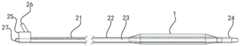
图2为图1所示的灌注球囊导管的注药球囊收缩时的结构示意图;Fig. 2 is a schematic diagram of the structure of the perfusion balloon catheter shown in Fig. 1 when the injection balloon is contracted;
图3为本发明实施例提供的灌注球囊导管的注药球囊的放大结构示意图;Fig. 3 is a schematic diagram of an enlarged structure of a drug injection balloon of a perfusion balloon catheter provided by an embodiment of the present invention;
图4为本发明实施例提供的灌注球囊导管的注药球囊的一种立体结构示意图;Fig. 4 is a schematic diagram of a three-dimensional structure of the injection balloon of the perfusion balloon catheter provided by the embodiment of the present invention;
图5为本发明实施例提供的灌注球囊导管的注药球囊的又一种立体结构示意图。Fig. 5 is a schematic diagram of another three-dimensional structure of the drug injection balloon of the perfusion balloon catheter provided by the embodiment of the present invention.
具体实施方式Detailed ways
为使本发明实施例的目的、技术方案和优点更加清楚,下面将结合附图对本发明的各实施方式进行详细的阐述。然而,本领域的普通技术人员可以理解,在本发明各实施方式中,为了使读者更好地理解本发明而提出了许多技术细节。但是,即使没有这些技术细节和基于以下各实施方式的种种变化和修改,也可以实现本发明所要求保护的技术方案。In order to make the purpose, technical solutions and advantages of the embodiments of the present invention more clear, various implementation modes of the present invention will be described in detail below in conjunction with the accompanying drawings. However, those of ordinary skill in the art can understand that in each implementation manner of the present invention, many technical details are proposed in order to enable readers to better understand the present invention. However, even without these technical details and various changes and modifications based on the following implementation modes, the technical solution claimed in the present invention can also be realized.
在本发明的描述中,需要说明的是,术语“上”、“下”、“内”、“外”等指示的方位或位置关系为基于附图所示的方位或位置关系,仅是为了便于描述本发明和简化描述,而不是指示或暗示所指的装置或元件必须具有特定的方位、以特定的方位构造和操作,因此不能理解为对本发明的限制。此外,术语“第一”、“第二”、“第三”等仅用于描述目的,而不能理解为指示或暗示相对重要性。In the description of the present invention, it should be noted that the orientation or positional relationship indicated by the terms "upper", "lower", "inner", "outer" and the like are based on the orientation or positional relationship shown in the accompanying drawings, and are only for It is convenient to describe the present invention and simplify the description, but does not indicate or imply that the device or element referred to must have a specific orientation, be constructed and operate in a specific orientation, and thus should not be construed as limiting the present invention. In addition, the terms "first", "second", "third", etc. are used for descriptive purposes only and should not be construed as indicating or implying relative importance.
需要说明的是,除非另有明确的规定,术语“相连”、“连接”等应做广义理解,例如,可以是固定连接,也可以是可拆卸连接,或一体地连接;可以是直接相连,也可以通过中间媒介间接相连,可以是两个元件内部的连通。It should be noted that, unless otherwise specified, the terms "connected" and "connected" should be understood in a broad sense, for example, it can be a fixed connection, a detachable connection, or an integral connection; it can be a direct connection, It can also be indirectly connected through an intermediary, and it can be the internal communication of two elements.
在本发明的描述中,需要说明的是,在介入医疗器械领域,近端是指距离操作者较近的一端,而远端是指距离操作者较远的一端;轴向是指平行于自然状态下的医疗器械远端中心和近端中心连线的方向。上述定义只是为了表述方便,并不能理解为对本发明的限制。In the description of the present invention, it should be noted that in the field of interventional medical devices, the proximal end refers to the end closer to the operator, while the distal end refers to the end farther away from the operator; the axial direction refers to the end parallel to the natural The direction of the line connecting the distal center and the proximal center of the medical device in the state. The above definitions are only for the convenience of expression, and should not be construed as limiting the present invention.
请参阅图1、图2所示,本发明实施例提供一种灌注球囊导管,用于将药物灌注到靶向位置,可适用于将药物灌注到血管内或者其他体腔内,以下主要针对血管内溶栓药物的灌注进行说明。本实施例的灌注球囊导管主要包括:注药球囊1和能够向注药球囊1内输注药液的导管组件。Please refer to Fig. 1 and Fig. 2, the embodiment of the present invention provides a perfusion balloon catheter, which is used to infuse drugs to target positions, and is suitable for infusing drugs into blood vessels or other body cavities. The following mainly focuses on blood vessels The perfusion of internal thrombolytic drugs will be described. The perfusion balloon catheter of this embodiment mainly includes: a drug injection balloon 1 and a catheter assembly capable of infusing a drug solution into the drug injection balloon 1 .
注药球囊1设置于导管组件远端并环绕导管组件设置。注药球囊1能够径向膨胀和收缩,且注药球囊1膨胀时具有围绕导管组件的灌注囊腔,导管组件与灌注囊腔连通并用于向灌注囊腔输注药液同时还使注药球囊1膨胀。注药球囊1外周壁布设有与灌注囊腔连通的多个灌注结构(图未示)。通过压握等可使注药球囊1排空收缩,便于将灌注球囊导管输送至血管内目标位置,通过导管组件持续向注药球囊1的灌注囊腔内输注药液,可使注药球囊1径向膨胀,使得注药球囊1外周壁挤压在血管内壁处的血栓上,此时,注药球囊1外周壁上的多个灌注结构能够直接接触血栓,药液可经过注药球囊1的灌注结构,比如灌注孔等近距离地释放在血栓处,且膨胀的注药球囊1能够减少血流对药物的稀释,使得血栓处能够持续保持足够的药物浓度,从而可实现高效率的溶栓,有利于缩短溶栓时长,且减少治疗所需药量。此外,注药球囊1径向膨胀时还具有轴向贯通的血流通道11,可立即开通血管通路,供血管内的血流通过,减轻病症。The injection balloon 1 is arranged at the distal end of the catheter assembly and surrounds the catheter assembly. The drug injection balloon 1 can expand and contract radially, and when the drug injection balloon 1 is inflated, it has a perfusion cavity surrounding the catheter assembly. The medicine balloon 1 is inflated. The peripheral wall of the injection balloon 1 is provided with a plurality of perfusion structures (not shown in the figure) communicating with the perfusion sac cavity. The drug injection balloon 1 can be emptied and contracted by pressing and gripping, so that the perfusion balloon catheter can be delivered to the target position in the blood vessel. The injection balloon 1 expands radially, so that the peripheral wall of the injection balloon 1 is squeezed on the thrombus at the inner wall of the blood vessel. At this time, the multiple perfusion structures on the peripheral wall of the injection balloon 1 can directly contact the thrombus, and the drug solution It can be released at the thrombus through the perfusion structure of the injection balloon 1, such as the perfusion hole, and the inflated injection balloon 1 can reduce the dilution of the drug by the blood flow, so that the thrombus can continuously maintain sufficient drug concentration , so that high-efficiency thrombolysis can be achieved, which is beneficial to shorten the duration of thrombolysis and reduce the amount of medicine required for treatment. In addition, when the injection balloon 1 is radially expanded, it also has an axially penetrating
导管组件可包括从近端到远端依次相连的管座25、导管管体21以及导管头端24。导管头端24凸伸出注药球囊1远端。导管头端24便于灌注球囊导管在血管内推进。管座25以及导管管体21内壁设置有与灌注囊腔连通的输送通道22。输送通道22可以为导管管体21内壁的沿导管管体21轴向延伸的通道,可以为环形通道或者半环形通道等,在此不做具体限制。管座25上还设有与输送通道22连通的灌注接头26。灌注接头26可以与注射器连接实现药物输注,然不限于此,灌注接头26也可以为与其他输注装置连接的接头形式。The catheter assembly may include a
导管组件还设有导丝腔23,导丝腔23内用于通过导丝,以引导灌注球囊导管到达目标血管位置。导丝腔23与输送通道22隔绝。可选地,管座25上还设有凸伸出管座25近端的导丝穿入口27,便于将导丝穿入导丝腔23内,通过导丝引导灌注球囊导管在血管内推进。The catheter assembly is also provided with a
请参阅图3~图5所示,注药球囊1可以为双层球囊,注药球囊1可包括内层13和外层12。内层13和外层12可粘接或者焊接形成注药球囊1。注药球囊1的内层13和外层12之间的接缝可以是圆形、椭圆形等合适的形状。可以理解的是,注药球囊1也可以为一体成型结构。Referring to FIGS. 3 to 5 , the injection balloon 1 can be a double-layer balloon, and the injection balloon 1 can include an
本实施例中,注药球囊1的灌注囊腔可以为一体连通的囊腔,输送通道22与灌注囊腔连通,并能够向灌注囊腔内快速输送药液。注药球囊1膨胀后可呈中空柱形,注药球囊1的长度可根据血栓的长度设置。注药球囊1的灌注囊腔为一体连通的囊腔时,也可以控制注药球囊1不同位置的注药速度,比如,可以在注药球囊1的轴向中心段设置更密的灌注结构,通过增大灌注结构的密度可以使注药球囊1的中部注药速度更快。然不限于此,灌注结构也可以均匀分布于注药球囊或者根据根据血栓的大小设置灌注结构的密度,比如,使得血栓较多的位置灌注结构的密度更大,血栓较少的位置灌注结构的密度较小。In this embodiment, the perfusion cavity of the drug injection balloon 1 may be an integrally connected cavity, and the
举例而言,导管组件的输送通道22与灌注囊腔之间可通过沿导管管体21轴向延伸的开口连通。即,导管组件可沿轴向均匀地向注药球囊1内注药,使得注药球囊1能够沿轴向均匀地膨胀。可以理解的是,本实施例对于输送通道与注药球囊的连接方式不做具体限制,只要能够通过输送通道向注药球囊1内顺利注药并使注药球囊1良好地膨胀即可。For example, the
注药球囊1与导管管体21可采用焊接或者粘接方式连接,具体地说,注药球囊1的远端和近端可以分别与导管管体21焊接或者粘接。并且,可以根据导管管体21上的开口位置使注药球囊1与导管管体21焊接或者粘接,同时使灌注囊腔与导管管体21上的输送通道连通。比如,导管管体21上用于连通注药球囊1和输送通道22的开口位置也可以位于注药球囊1两端,此时注药球囊1和导管管体21在注药球囊1的两端位置处焊接。本实施例中,注药球囊1远端和/或近端具有过渡连接至导管管体21的肩部15。The drug injection balloon 1 and the
值得一提的是,注药球囊1的灌注囊腔也可以分为若干个周向相隔绝的子腔,且导管组件用于分别向各个子腔输注药液。比如,注药球囊1具有2个或者3个周向相分隔的子腔,而导管组件能够分别向各个子腔输注药液,因此可便于控制向各个子腔输注药液的速度,如果某个子腔对应的注药区域的血栓量较大,则可对应提高输液速度和流量;反之,若某个子腔对应的注药区域的血栓量较小,则可对应降低输液速度以适当减少注药量。It is worth mentioning that the perfusion cavity of the drug injection balloon 1 can also be divided into several circumferentially isolated sub-cavities, and the catheter assembly is used to infuse the drug solution into each sub-cavity. For example, the drug injection balloon 1 has 2 or 3 sub-cavities separated in the circumferential direction, and the catheter assembly can infuse the liquid medicine into each sub-cavity, so it is convenient to control the speed of infusion of the liquid medicine to each sub-cavity. If the amount of thrombus in the injection area corresponding to a sub-cavity is relatively large, the infusion speed and flow rate can be increased accordingly; on the contrary, if the thrombus volume in the injection area corresponding to a certain sub-cavity is small, the infusion speed can be correspondingly reduced to reduce the injection rate appropriately. quantity.
本实施例中,注药球囊1的血流通道11可与导管组件偏心设置。即,注药球囊1的一侧与导管管体21相连,而注药球囊1膨胀时与导管管体21之间形成血流通道11,使得导管管体21偏置于血管内,血管内的血流可通过血流通道11正常流动。可选地,血流通道11的截面可呈圆形或者椭圆形。In this embodiment, the
可以理解的是,注药球囊1的血流通道11也可与导管组件同心设置。此时,注药球囊1远端和近端可与导管管体21相连,并使得灌注囊腔与导管管体21上的输送通道连通。注药球囊1膨胀时,导管管体21居中,血流可通过注药球囊1和导管管体21之间的血流通道通过。It can be understood that the
注药球囊1上的灌注结构(图未示)可为灌注孔或者灌注缝。灌注孔可呈圆形或者椭圆形。灌注孔或者灌注缝结构可以设置为在一定压力下开通,即当向灌注囊腔内输入药液,灌注囊腔膨胀后且其内的压力达到一定值时,灌注结构打开,实现药液施注,从而有利于注药球囊1快速膨胀以及节省药量。灌注结构可以为任意有利于球囊膨胀以及药液喷注的孔或者缝隙等的结构。多个灌注结构可均匀分布于注药球囊1外周壁或者按照一定规则排列分布。可以理解的是,灌注结构的形状、分布以及数量等均可以根据病变位置进行调整,在此均不做具体限制。The perfusion structure (not shown) on the drug injection balloon 1 can be perfusion holes or perfusion slits. The perfusion hole can be round or oval. The perfusion hole or perfusion slit structure can be set to open under a certain pressure, that is, when the liquid medicine is injected into the perfusion sac cavity, and the perfusion sac cavity expands and the pressure in it reaches a certain value, the perfusion structure opens to realize the liquid medicine injection. , so as to facilitate the rapid expansion of the drug injection balloon 1 and save the amount of medicine. The perfusion structure can be any hole or slit that is conducive to balloon expansion and liquid medicine injection. Multiple perfusion structures can be evenly distributed on the peripheral wall of the injection balloon 1 or arranged and distributed according to certain rules. It can be understood that the shape, distribution and quantity of the perfusion structure can be adjusted according to the location of the lesion, which are not specifically limited here.
灌注球囊导管还可包括至少一显影环(图未示)。显影环可设置于导管管体21上,通过显影环可便于确定注药球囊1在血管中的位置。示例性地,灌注球囊导管可包括两个显影环,两个显影环可分别设置于注药球囊1两端的导管管体21上,亦或设置于注药球囊1的肩部15对应的导管管体21上,从而可方便地确定注药球囊的位置。显影环可固定套接于导管管体21上。The perfusion balloon catheter may also include at least one visualization ring (not shown). The developing ring can be arranged on the
请参阅图1所示,本实施例的灌注球囊导管的使用方法如下:Please refer to Fig. 1, the usage method of the perfusion balloon catheter of the present embodiment is as follows:
将本灌注球囊导管沿导丝送入到血管位置,通过导管组件向注药球囊1内注入药液,药液充入灌注囊腔后,注药球囊1径向膨胀后其外壁与病变位置紧密接触,药液在压力的作用下从球囊外壁的小孔处渗出到病变位置。由于球囊的挤压遮挡作用,药液不能自由流动也不会被血流冲到其他位置,从而可以更好地在病变处作用,使得病变处持续保持足够的药物浓度,进而提高治疗效率和治疗效果。The perfusion balloon catheter is sent to the blood vessel along the guide wire, and the drug solution is injected into the injection balloon 1 through the catheter assembly. After the drug solution is filled into the perfusion cavity, the outer wall of the drug injection balloon 1 is radially expanded and The lesions are in close contact, and the liquid medicine seeps out from the small hole on the outer wall of the balloon to the lesions under the action of pressure. Due to the extrusion and shielding effect of the balloon, the liquid medicine cannot flow freely and will not be rushed to other positions by the blood flow, so that it can work better on the lesion, so that the lesion can maintain sufficient drug concentration, thereby improving the treatment efficiency and treatment effect.
基于上述技术方案本发明至少具有如下优点和积极效果:Based on the above-mentioned technical scheme, the present invention has at least the following advantages and positive effects:
本发明实施例的灌注球囊导管中,注药球囊设置于导管组件远端并环绕导管组件设置,且注药球囊径向膨胀时具有围绕导管组件的灌注囊腔以及轴向贯通的血流通道,通过导管组件向灌注囊腔输注药液可使注药球囊膨胀并挤压在血管内壁的血栓上,通过注药球囊上的灌注结构可以直接将药液施加在血栓处,使得血栓处能够持续保持足够的药物浓度,从而提高溶栓效率,缩短溶栓时长和减少药物量。并且,注药球囊膨胀时具有血流通道,从而可以快速开通血流通路,减轻病症。In the perfusion balloon catheter of the embodiment of the present invention, the drug injection balloon is arranged at the distal end of the catheter assembly and is arranged around the catheter assembly, and when the drug injection balloon radially expands, it has a perfusion sac cavity surrounding the catheter assembly and a blood flow through the catheter assembly axially. The flow channel, infusion of the drug solution into the perfusion sac cavity through the catheter assembly can cause the drug injection balloon to expand and squeeze on the thrombus on the inner wall of the blood vessel, and the drug solution can be directly applied to the thrombus through the perfusion structure on the drug injection balloon. It enables the thrombus to maintain sufficient drug concentration continuously, thereby improving the efficiency of thrombolysis, shortening the duration of thrombolysis and reducing the amount of drugs. Moreover, the injection balloon has a blood flow channel when it is inflated, so that the blood flow channel can be quickly opened and the symptoms can be alleviated.
本领域的普通技术人员可以理解,上述各实施方式是实现本发明的具体实施例,而在实际应用中,可以在形式上和细节上对其作各种改变,而不偏离本发明的精神和范围。Those of ordinary skill in the art can understand that the above-mentioned embodiments are specific examples for realizing the present invention, and in practical applications, various changes can be made to it in form and details without departing from the spirit and spirit of the present invention. scope.
Claims (10)
Priority Applications (1)
| Application Number | Priority Date | Filing Date | Title |
|---|---|---|---|
| CN202310160973.0ACN115990312A (en) | 2023-02-23 | 2023-02-23 | Perfusion balloon catheter |
Applications Claiming Priority (1)
| Application Number | Priority Date | Filing Date | Title |
|---|---|---|---|
| CN202310160973.0ACN115990312A (en) | 2023-02-23 | 2023-02-23 | Perfusion balloon catheter |
Publications (1)
| Publication Number | Publication Date |
|---|---|
| CN115990312Atrue CN115990312A (en) | 2023-04-21 |
Family
ID=85990419
Family Applications (1)
| Application Number | Title | Priority Date | Filing Date |
|---|---|---|---|
| CN202310160973.0APendingCN115990312A (en) | 2023-02-23 | 2023-02-23 | Perfusion balloon catheter |
Country Status (1)
| Country | Link |
|---|---|
| CN (1) | CN115990312A (en) |
Citations (4)
| Publication number | Priority date | Publication date | Assignee | Title |
|---|---|---|---|---|
| US20170056628A1 (en)* | 2015-03-04 | 2017-03-02 | Transmed7, Llc | Steerable, conformable, drug eluting balloon catheter |
| CN108367137A (en)* | 2015-11-06 | 2018-08-03 | 巴德股份有限公司 | Infusing balloon with selectively actuatable valve |
| CN111298274A (en)* | 2020-05-14 | 2020-06-19 | 上海脉全医疗器械有限公司 | Medicine balloon and using method thereof |
| CN114159676A (en)* | 2020-09-09 | 2022-03-11 | 上海鸿脉医疗科技有限公司 | Balloon catheter |
- 2023
- 2023-02-23CNCN202310160973.0Apatent/CN115990312A/enactivePending
Patent Citations (4)
| Publication number | Priority date | Publication date | Assignee | Title |
|---|---|---|---|---|
| US20170056628A1 (en)* | 2015-03-04 | 2017-03-02 | Transmed7, Llc | Steerable, conformable, drug eluting balloon catheter |
| CN108367137A (en)* | 2015-11-06 | 2018-08-03 | 巴德股份有限公司 | Infusing balloon with selectively actuatable valve |
| CN111298274A (en)* | 2020-05-14 | 2020-06-19 | 上海脉全医疗器械有限公司 | Medicine balloon and using method thereof |
| CN114159676A (en)* | 2020-09-09 | 2022-03-11 | 上海鸿脉医疗科技有限公司 | Balloon catheter |
Similar Documents
| Publication | Publication Date | Title |
|---|---|---|
| CN215386905U (en) | A shock wave assisted drug perfusion balloon catheter and medical equipment | |
| CN112188912B (en) | Multi-diameter catheters and related devices and methods | |
| US5378230A (en) | Triple-lumen critical care catheter | |
| US5167628A (en) | Aortic balloon catheter assembly for indirect infusion of the coronary arteries | |
| US20160263347A1 (en) | Multi-lumen biologic-delivering device | |
| CN203852722U (en) | Aspiration and injection catheter apparatus with flow-limiting bladders | |
| CN113289212A (en) | Shock wave auxiliary medicine perfusion balloon catheter and medical equipment | |
| CN205903514U (en) | Multicavity way sacculus pipe | |
| CN113633875A (en) | A double lumen angiography catheter | |
| CN115463321B (en) | Administration balloon catheter and administration balloon catheter device | |
| CN116688327A (en) | Catheter device and heart failure therapeutic apparatus | |
| CN216495501U (en) | Thrombolysis guide wire | |
| CN107684644A (en) | It is pre- to rush formula flushing syringe infusion pump combination bag | |
| CN106039540A (en) | Double-sleeve nasogastric tube allowing outward drainage of irrigating fluid and drainage and injecting method thereof | |
| CN216168131U (en) | A retractable drug perfusion stent system | |
| CN115990312A (en) | Perfusion balloon catheter | |
| CN114916991A (en) | Integrated thrombolytic perfusion catheter assembly | |
| CN116899045B (en) | A high-performance implantable infusion port | |
| CN211131355U (en) | Guide wire guiding double-layer balloon catheter for chemical ablation of blood vessels | |
| CN211050658U (en) | Guide wire guiding balloon catheter for chemical ablation of blood vessels | |
| CN218923533U (en) | Drug-loaded balloons and drug delivery balloon catheters | |
| CN112638460B (en) | Balloon within balloon catheter systems and methods of use | |
| CN209123141U (en) | A double-balloon thrombolytic catheter | |
| CN217448679U (en) | Extension catheter and interventional medical device | |
| CN216986023U (en) | Safe leak-proof urine irrigation catheter |
Legal Events
| Date | Code | Title | Description |
|---|---|---|---|
| PB01 | Publication | ||
| PB01 | Publication | ||
| SE01 | Entry into force of request for substantive examination | ||
| SE01 | Entry into force of request for substantive examination |