CN115977475A - Door locks and folding door refrigerators - Google Patents
Door locks and folding door refrigeratorsDownload PDFInfo
- Publication number
- CN115977475A CN115977475ACN202211555744.0ACN202211555744ACN115977475ACN 115977475 ACN115977475 ACN 115977475ACN 202211555744 ACN202211555744 ACN 202211555744ACN 115977475 ACN115977475 ACN 115977475A
- Authority
- CN
- China
- Prior art keywords
- door
- push rod
- locking
- locking part
- door lock
- Prior art date
- Legal status (The legal status is an assumption and is not a legal conclusion. Google has not performed a legal analysis and makes no representation as to the accuracy of the status listed.)
- Pending
Links
Images


Landscapes
- Lock And Its Accessories (AREA)
Abstract
Description
Translated fromChinese技术领域technical field
本发明涉及门锁技术领域,尤其涉及一种门锁和叠门冰箱。The invention relates to the technical field of door locks, in particular to a door lock and a refrigerator with folding doors.
背景技术Background technique
随着冰箱技术的不断发展,冰箱的种类也越来越多,例如单门冰箱、多门冰箱、法式冰箱、叠门冰箱等各种不同的冰箱逐步出现在家庭之中,其中,叠门冰箱由于容积率高、外观和配置都较为高端等原因而非常受用户的欢迎。With the continuous development of refrigerator technology, there are more and more types of refrigerators, such as single-door refrigerators, multi-door refrigerators, French refrigerators, folding door refrigerators and other refrigerators gradually appearing in families. Among them, folding door refrigerators It is very popular with users due to its high volume ratio, high-end appearance and configuration.
但在叠门冰箱的使用过程中,经常出现在开关一个门时对另一个门产生影响的情况,例如出现打开内门的同时外门由于惯性等原因异常打开,这些异常的开关门情况不仅影响用户体验,而且会带来一定的安全隐患。However, during the use of folding-door refrigerators, opening and closing of one door often affects the other door. For example, when opening the inner door, the outer door opens abnormally due to inertia and other reasons. User experience, and will bring certain security risks.
需要说明的是,公开于本发明背景技术部分的信息仅仅旨在增加对本发明的总体背景的理解,而不应当被视为承认或以任何形式暗示该信息构成已为本领域技术人员所公知的现有技术。It should be noted that the information disclosed in the background technology section of the present invention is only intended to increase the understanding of the general background of the present invention, and should not be considered as an acknowledgment or in any form to imply that the information constitutes knowledge already known to those skilled in the art. current technology.
发明内容Contents of the invention
本发明提供一种门锁和叠门冰箱,可以有效避免叠门冰箱使用过程中的冰箱门异常开关的情况发生。The invention provides a door lock and a folding-door refrigerator, which can effectively prevent abnormal opening and closing of the refrigerator door during the use of the folding-door refrigerator.
根据本发明的一个方面,提供一种门锁,被配置为使第二门相对于第一门锁止和解锁,包括:According to an aspect of the present invention, there is provided a door lock configured to lock and unlock a second door relative to the first door, comprising:
第一锁止部,被配置为安装于第一门;the first locking part is configured to be installed on the first door;
第二锁止部,被配置为安装于第二门,第二锁止部具有第一位置和第二位置,在第一位置,第二锁止部与第一锁止部配合以使第二门相对于第一门锁止,在第二位置,第二锁止部与第一锁止部解除配合以使第二门相对于第一门解锁;和The second locking part is configured to be installed on the second door. The second locking part has a first position and a second position. In the first position, the second locking part cooperates with the first locking part so that the second the door is locked relative to the first door, and in the second position, the second locking portion disengages from the first locking portion to unlock the second door relative to the first door; and
驱动装置,被配置为驱动第二锁止部运动,以实现第二锁止部在第一位置与第二位置之间的切换。The driving device is configured to drive the second locking part to move, so as to realize the switch between the first position and the second position of the second locking part.
在一些实施例中,In some embodiments,
第一锁止部包括凸起部、凹入部或锁孔;The first locking part includes a protrusion, a recess or a lock hole;
第二锁止部包括锁钩,在第一位置,锁钩钩挂于凸起部、凹入部或锁孔以使第二门相对于第一门锁止,在第二位置锁钩脱离凸起部、凹入部或锁孔以使第二门相对于第一门解锁;The second locking part includes a lock hook. In the first position, the lock hook is hooked on the protrusion, the recess or the lock hole to lock the second door relative to the first door. In the second position, the lock hook breaks away from the protrusion. portion, recess or lockhole to unlock the second door relative to the first door;
驱动装置被配置为驱动锁钩运动,以实现锁钩在第一位置与第二位置之间的切换。The driving device is configured to drive the locking hook to move, so as to realize switching between the first position and the second position of the locking hook.
在一些实施例中,门锁还包括:In some embodiments, the door lock also includes:
第一壳体,用于与第一门连接,第一锁止部安装于第一壳体内;和/或The first housing is used to connect with the first door, and the first locking part is installed in the first housing; and/or
第二壳体,用于与第二门连接,第二锁止部可动地安装于第二壳体内。The second casing is used for connecting with the second door, and the second locking part is movably installed in the second casing.
在一些实施例中,In some embodiments,
驱动装置被配置为驱动第二锁止部沿第一方向转动,以使第二锁止部的第二端脱离第一锁止部,从而使第二锁止部从第一位置切换到第二位置;The driving device is configured to drive the second locking part to rotate along the first direction, so that the second end of the second locking part is disengaged from the first locking part, so that the second locking part switches from the first position to the second position. Location;
驱动装置被配置为驱动第二锁止部沿第二方向转动,以使第二锁止部的第二端与第一锁止部配合,从而使第二锁止部从第二位置切换到第一位置,第二方向与第一方向相反。The driving device is configured to drive the second locking part to rotate along the second direction, so that the second end of the second locking part cooperates with the first locking part, so that the second locking part switches from the second position to the first locking part. A position, the second direction is opposite to the first direction.
在一些实施例中,驱动装置包括:In some embodiments, the driving device includes:
机械驱动机构,被配置为驱动第二锁止部从第一位置向第二位置切换和/或从第二位置向第一位置切换;和/或a mechanical drive mechanism configured to drive the second locking portion to switch from the first position to the second position and/or from the second position to the first position; and/or
电磁驱动机构,被配置为驱动第二锁止部从第一位置向第二位置切换和/或从第二位置向第一位置切换。The electromagnetic driving mechanism is configured to drive the second locking part to switch from the first position to the second position and/or from the second position to the first position.
在一些实施例中,机械驱动机构包括:In some embodiments, the mechanical drive mechanism includes:
固定件,被配置为安装于第二门;a fixing member configured to be mounted on the second door;
转动件,可转动地连接于固定件;和a rotating member rotatably connected to the fixed member; and
第一推杆,与转动件可活动地连接,转动件被配置为相对于固定件转动使第一推杆相对于固定件平移以靠近或远离第二锁止部,第一推杆靠近第二锁止部驱动第二锁止部从第一位置向第二位置切换。The first push rod is movably connected with the rotating part. The rotating part is configured to rotate relative to the fixed part so that the first push rod translates relative to the fixed part to approach or move away from the second locking part. The first push rod is close to the second locking part. The locking part drives the second locking part to switch from the first position to the second position.
在一些实施例中,In some embodiments,
电磁驱动机构包括:The electromagnetic drive mechanism includes:
第二推杆,第二推杆由导磁材料制成;和a second push rod, the second push rod is made of a magnetically permeable material; and
第一电磁铁,第一电磁铁被配置为得电时产生使第二推杆向靠近第二锁止部的方向运动的电磁力,以通过第二推杆驱动第二锁止部从第一位置切换至第二位置;The first electromagnet, the first electromagnet is configured to generate an electromagnetic force that makes the second push rod move toward the direction close to the second locking part when it is energized, so as to drive the second locking part from the first locking part through the second pushing rod. switch position to second position;
其中,第一推杆位于第二推杆的远离第二锁止部的一端,第一推杆通过第二推杆驱动第二锁止部从第一位置向第二位置切换。Wherein, the first push rod is located at an end of the second push rod away from the second locking part, and the first push rod drives the second locking part to switch from the first position to the second position through the second push rod.
在一些实施例中,In some embodiments,
门锁还包括第二壳体,第二壳体用于与第二门连接,第二锁止部可动地安装于第二壳体内,固定件设置于第二壳体内,第二壳体设有开口;The door lock also includes a second housing, the second housing is used to connect with the second door, the second locking part is movably installed in the second housing, the fixing part is arranged in the second housing, and the second housing is provided with has an opening;
转动件包括从开口伸出的持握部,以通过驱动持握部使转动件相对于固定件转动。The rotating part includes a holding part protruding from the opening, so as to rotate the rotating part relative to the fixed part by driving the holding part.
在一些实施例中,固定件设有第一安装槽,第一推杆设有第二安装槽,转动件包括:In some embodiments, the fixed part is provided with a first installation groove, the first push rod is provided with a second installation groove, and the rotating part includes:
第一连接杆,可转动地设置于第一安装槽中;和the first connecting rod is rotatably disposed in the first installation groove; and
第二连接杆,可转动且在垂直于第二连接杆的转动轴线的方向沿第二安装槽的槽壁可滑动地设置于第二安装槽中。The second connecting rod is rotatable and is slidably arranged in the second installing groove along the groove wall of the second installing groove in a direction perpendicular to the rotation axis of the second connecting rod.
在一些实施例中,固定件上设有滑道,第一推杆与滑道滑动配合。In some embodiments, a sliding track is provided on the fixing member, and the first push rod is slidingly engaged with the sliding track.
在一些实施例中,驱动装置还包括第一复位机构,第一复位机构被配置为向第一推杆施加使其趋于远离第二锁止部的力。In some embodiments, the driving device further includes a first reset mechanism configured to apply a force to the first push rod to tend to move away from the second locking portion.
在一些实施例中,In some embodiments,
固定件的靠近第二锁止部的一端包括第一凸缘部;One end of the fixing part close to the second locking part includes a first flange part;
第一推杆的远离第二锁止部的一端包括第二凸缘部,第一凸缘部位于第二锁止部与第二凸缘部之间;An end of the first push rod away from the second locking part includes a second flange part, and the first flange part is located between the second locking part and the second flange part;
第一复位机构包括第一复位弹簧,第一复位弹簧设置于第一凸缘部与第二凸缘部之间,第一复位弹簧被配置向第二凸缘部施加使其趋于远离第二锁止部的力。The first return mechanism includes a first return spring, the first return spring is arranged between the first flange part and the second flange part, and the first return spring is configured to apply to the second flange part so that it tends to move away from the second flange part. The force of the locking part.
在一些实施例中,固定件上设有滑道,第一推杆与滑道滑动配合,滑道包括设置于第一凸缘部的第一通孔,第一推杆穿设于第一通孔中,第一复位弹簧套设于第一推杆的位于第一凸缘部与第二凸缘部之间的杆段上。In some embodiments, a slideway is provided on the fixing part, and the first push rod is slidably matched with the slideway. In the hole, the first return spring is sleeved on the rod section of the first push rod between the first flange part and the second flange part.
在一些实施例中,固定件的远离第二锁止部的一端包括第三凸缘部,滑道包括设置于第三凸缘部的第二通孔,第一推杆的远离第二锁止部的端部穿设于第二通孔中,第二凸缘部位于第一凸缘部与第三凸缘部之间。In some embodiments, the end of the fixing member away from the second locking part includes a third flange part, the slideway includes a second through hole disposed on the third flange part, and the end of the first push rod away from the second locking part The end of the part is passed through the second through hole, and the second flange part is located between the first flange part and the third flange part.
在一些实施例中,转动件包括第一连接杆、第二连接杆和两个支臂,第一连接杆和第二连接杆分别连接于两个支臂之间,第一连接杆可转动地连接于固定件,第二连接杆与第一推杆的第二凸缘部可转动且沿垂直于第二连接杆的转动方向可平移地活动连接,第三凸缘部位于两个支臂之间。In some embodiments, the rotating member includes a first connecting rod, a second connecting rod and two arms, the first connecting rod and the second connecting rod are respectively connected between the two supporting arms, and the first connecting rod is rotatably Connected to the fixing part, the second connecting rod and the second flange of the first push rod are rotatably connected in a translational manner along a direction perpendicular to the rotation of the second connecting rod, and the third flange is located between the two arms between.
在一些实施例中,电磁驱动机构被配置为在得电时驱动第二锁止部从第一位置切换至第二位置。In some embodiments, the electromagnetic driving mechanism is configured to drive the second locking part to switch from the first position to the second position when powered on.
在一些实施例中,电磁驱动机构包括:In some embodiments, the electromagnetic drive mechanism includes:
第一电磁铁和第二推杆,第二推杆由导磁材料制成,第一电磁铁被配置为得电时产生使第二推杆向靠近第二锁止部的方向运动的电磁力,以通过第二推杆驱动第二锁止部从第一位置切换至第二位置;或The first electromagnet and the second push rod, the second push rod is made of magnetically permeable material, and the first electromagnet is configured to generate an electromagnetic force that moves the second push rod toward the direction close to the second locking part when it is energized , to drive the second locking part to switch from the first position to the second position through the second push rod; or
第二电磁铁,第二锁止部由导磁材料制成,第二电磁铁被配置为在得电时产生吸附第二锁止部的电磁力,以驱动第二锁止部从第一位置切换至第二位置。The second electromagnet, the second locking part is made of magnetically conductive material, the second electromagnet is configured to generate an electromagnetic force that attracts the second locking part when energized, so as to drive the second locking part from the first position Switch to second position.
在一些实施例中,驱动装置还包括第二复位机构,第二复位机构被配置为向第二锁止部施加使其趋于向第一位置切换的力。In some embodiments, the driving device further includes a second reset mechanism configured to apply a force to the second locking portion to tend to switch to the first position.
在一些实施例中,In some embodiments,
门锁包括第二壳体,第二壳体用于与第二门连接,第二锁止部可动地安装于第二壳体内;The door lock includes a second housing, the second housing is used to connect with the second door, and the second locking part is movably installed in the second housing;
第二复位机构包括第二复位弹簧,第二复位弹簧设置于第二锁止部与第二壳体之间。The second return mechanism includes a second return spring, and the second return spring is arranged between the second locking portion and the second housing.
在一些实施例中,In some embodiments,
第二锁止部包括锁止部本体和设置于锁止部本体的止挡部,止挡部内设有避让孔;The second locking part includes a locking part body and a stop part arranged on the locking part body, and an avoidance hole is arranged in the stop part;
第二壳体上设有朝向止挡部一侧凸出并伸入避让孔内的安装柱;The second housing is provided with a mounting column that protrudes toward the side of the stopper and extends into the avoidance hole;
第二复位弹簧套设于安装柱上,第二复位弹簧的两端分别抵靠在止挡部和第二壳体上,第二复位弹簧被配置为向止挡部施加使其趋于远离第二壳体的设有安装柱的位置的力。The second return spring is sheathed on the mounting column, and the two ends of the second return spring respectively abut against the stop part and the second housing, and the second return spring is configured to apply force to the stop part so that it tends to move away from the first The force of the position of the second shell is provided with the mounting column.
根据本发明的另一个方面,提供一种叠门冰箱,包括:According to another aspect of the present invention, there is provided a folding door refrigerator, comprising:
第一门;first door;
第二门,与第一门平行;和a second door, parallel to the first; and
上述门锁,门锁的第一锁止部安装于第一门,门锁的第二锁止部安装于第二门。In the above door lock, the first locking part of the door lock is installed on the first door, and the second locking part of the door lock is installed on the second door.
基于上述技术方案,本发明通过设置分别被配置为安装于第一门和第二门的第一锁止部和第二锁止部,并将第二锁止部设置为与第一锁止部配合/解除配合以使第二门相对于第一门锁止/解锁,则可以实现在第二门相对于第一门锁止时,打开或者关闭第一门不会导致第二门的异常打开,在第二门相对于第一门解锁时,打开或者关闭第二门的动作也不会对第一门的开闭状态造成影响,从而保障第一门和第二门的工作可靠性。而通过将第二锁止部设置为具有第一位置和第二位置,且在第一位置时使第二门相对于第一门的锁止,在第二位置时使第二门相对于第一门解锁,并设置用于实现第二锁止部在第一位置与第二位置之间的切换的驱动装置,则通过控制驱动装置便可以实现对第二门相对于第一门的锁止和解锁状态的控制,操作方便,有助于提升用户体验。Based on the above technical solution, the present invention sets a first locking part and a second locking part which are respectively configured to be installed on the first door and the second door, and sets the second locking part to be compatible with the first locking part. Mating/disengaging to lock/unlock the second door relative to the first door, it can be realized that when the second door is locked relative to the first door, opening or closing the first door will not cause abnormal opening of the second door , when the second door is unlocked relative to the first door, the action of opening or closing the second door will not affect the opening and closing state of the first door, thereby ensuring the working reliability of the first door and the second door. And by setting the second locking part to have a first position and a second position, and make the second door lock relative to the first door when in the first position, make the second door lock relative to the first door when in the second position. One door is unlocked, and a driving device is provided for switching the second locking part between the first position and the second position, then the locking of the second door relative to the first door can be realized by controlling the driving device And unlock state control, easy to operate, help to improve user experience.
附图说明Description of drawings
此处所说明的附图用来提供对本发明的进一步理解,构成本申请的一部分,本发明的示意性实施例及其说明用于解释本发明,并不构成对本发明的不当限定。在附图中:The accompanying drawings described here are used to provide a further understanding of the present invention and constitute a part of the application. The schematic embodiments of the present invention and their descriptions are used to explain the present invention and do not constitute improper limitations to the present invention. In the attached picture:
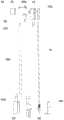
图1示出了本发明门锁一个实施例的结构示意图;Fig. 1 shows the structural representation of an embodiment of the door lock of the present invention;
图2a和图2b分别示出了本发明门锁一个实施例中第二锁止部处于第一位置和第二位置的示意图;Fig. 2a and Fig. 2b respectively show the schematic diagrams of the second locking part in the first position and the second position in one embodiment of the door lock of the present invention;
图3a和图3b分别示出了本发明门锁又一个实施例中第二锁止部处于第一位置和第二位置的示意图;Fig. 3a and Fig. 3b respectively show the schematic diagrams of the second locking part in the first position and the second position in another embodiment of the door lock of the present invention;
图4a和图4b分别示出了本发明门锁一个实施例中第二锁止部处于第一位置和第二位置时机械驱动机构的结构示意图;Fig. 4a and Fig. 4b respectively show the structural schematic diagrams of the mechanical driving mechanism when the second locking part is in the first position and the second position in one embodiment of the door lock of the present invention;
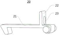
图5示出了本发明门锁一个实施例中第二锁止部的结构示意图;Fig. 5 shows a schematic structural view of the second locking part in an embodiment of the door lock of the present invention;
图6示出了本发明门锁一个实施例中固定件的结构示意图;Fig. 6 shows a schematic structural view of a fixing part in an embodiment of the door lock of the present invention;
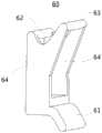
图7示出了本发明门锁一个实施例中转动件的结构示意图;Fig. 7 shows a structural schematic diagram of a rotating member in an embodiment of the door lock of the present invention;
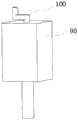
图8示出了本发明门锁一个实施例中第一电磁铁和第二推杆的装配示意图;Fig. 8 shows a schematic diagram of the assembly of the first electromagnet and the second push rod in one embodiment of the door lock of the present invention;
图9示出了本发明门锁一个实施例中第一推杆和第一复位弹簧的装配示意图;Fig. 9 shows a schematic diagram of the assembly of the first push rod and the first return spring in one embodiment of the door lock of the present invention;
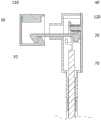
图10示出了本发明门锁一个实施例中驱动装置的结构示意图;Fig. 10 shows a schematic structural view of the driving device in an embodiment of the door lock of the present invention;
图11示出了本发明门锁另一个实施例中驱动装置的结构示意图;Fig. 11 shows a schematic structural view of the driving device in another embodiment of the door lock of the present invention;
图12示出了本发明门锁一个实施例中机械驱动机构的结构示意图;Fig. 12 shows a schematic structural view of a mechanical drive mechanism in an embodiment of the door lock of the present invention;
图13示出了本发明门锁一个实施例的爆炸图;Figure 13 shows an exploded view of an embodiment of the door lock of the present invention;
图14示出了本发明叠门冰箱一个实施例中第一门、第二门和门锁的装配示意图。Fig. 14 shows an assembly diagram of the first door, the second door and the door lock in an embodiment of the folding door refrigerator of the present invention.
图中:In the picture:
1、第一门;2、第二门;1. The first door; 2. The second door;
10、第一锁止部;10. The first locking part;
20、第二锁止部;21、锁止部本体;22、止挡部;23、避让孔;20. Second locking part; 21. Locking part body; 22. Stopper part; 23. Avoidance hole;
30、第一壳体;30. The first casing;
40、第二壳体;40a、第一壳盖;40b、第一壳身;40c、第二壳盖;40d、第二壳身;40e、导管;41、安装柱;40, the second shell; 40a, the first shell cover; 40b, the first shell body; 40c, the second shell cover; 40d, the second shell body; 40e, the conduit; 41, the installation column;
50、固定件;50a、第一安装槽;51、第一凸缘部;51a、第一通孔;52、第三凸缘部;52a、第二通孔;50, fixing piece; 50a, first installation groove; 51, first flange portion; 51a, first through hole; 52, third flange portion; 52a, second through hole;
60、转动件;61、持握部;62、第一连接杆;63、第二连接杆;64、支臂;60. Rotating member; 61. Grip; 62. First connecting rod; 63. Second connecting rod; 64. Support arm;
70、第一推杆;70a、第二安装槽;71、第二凸缘部;70, the first push rod; 70a, the second installation groove; 71, the second flange part;
80、第一复位弹簧;90、第一电磁铁;100、第二推杆;110、第二电磁铁;120、第二复位弹簧。80, the first return spring; 90, the first electromagnet; 100, the second push rod; 110, the second electromagnet; 120, the second return spring.
具体实施方式Detailed ways
下面将结合本发明实施例中的附图,对实施例中的技术方案进行清楚、完整地描述。显然,所描述的实施例仅仅是本发明的一部分实施例,而不是全部的实施例。基于本发明的实施例,本领域普通技术人员在没有做出创造性劳动前提下所获得的所有其他实施例,都属于本发明保护的范围。The technical solutions in the embodiments of the present invention will be clearly and completely described below in conjunction with the drawings in the embodiments of the present invention. Apparently, the described embodiments are only some of the embodiments of the present invention, not all of them. Based on the embodiments of the present invention, all other embodiments obtained by persons of ordinary skill in the art without making creative efforts fall within the protection scope of the present invention.
在本发明的描述中,需要理解的是,术语“中心”、“横向”、“纵向”、“前”、“后”、“左”、“右”、“上”、“下”、“竖直”、“水平”、“顶”、“底”、“内”、“外”等指示的方位或位置关系为基于附图所示的方位或位置关系,仅是为了便于描述本发明和简化描述,而不是指示或暗示所指的装置或元件必须具有特定的方位、以特定的方位构造和操作,因此不能理解为对本发明保护范围的限制。In describing the present invention, it should be understood that the terms "center", "transverse", "longitudinal", "front", "rear", "left", "right", "upper", "lower", " The orientations or positional relationships indicated by "vertical", "horizontal", "top", "bottom", "inner" and "outer" are based on the orientations or positional relationships shown in the drawings, and are only for the convenience of describing the present invention and Simplified descriptions, rather than indicating or implying that the device or element referred to must have a specific orientation, be constructed and operate in a specific orientation, and thus should not be construed as limiting the scope of the present invention.
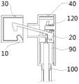
参考图1和图14所示,本发明提供的门锁被配置为使第二门2相对于第一门1锁止和解锁,在一些实施例中,该门锁包括第一锁止部10、第二锁止部20和驱动装置,第一锁止部10被配置为安装于第一门1,第二锁止部20被配置为安装于第二门2;第二锁止部20具有第一位置和第二位置,在第一位置,第二锁止部20与第一锁止部10配合以使第二门2相对于第一门1锁止,在第二位置,第二锁止部20与第一锁止部10解除配合以使第二门2相对于第一门1解锁;驱动装置被配置为驱动第二锁止部20运动,以实现第二锁止部20在第一位置与第二位置之间的切换。1 and 14, the door lock provided by the present invention is configured to lock and unlock the
通过设置分别被配置为安装于第一门1和第二门2的第一锁止部10和第二锁止部20,并将第二锁止部20设置为与第一锁止部10配合/解除配合以使第二门2相对于第一门1锁止/解锁,则可以实现在第二门2相对于第一门1锁止时,打开或者关闭第一门1不会导致第二门2的异常打开,在第二门2相对于第一门1解锁时,打开或者关闭第二门2的动作也不会对第一门1的开闭状态造成影响,从而保障第一门1和第二门2的工作可靠性。By providing the
而通过将第二锁止部20设置为具有第一位置和第二位置,且在第一位置时使第二门2相对于第一门1的锁止,在第二位置时使第二门2相对于第一门1解锁,并设置用于实现第二锁止部20在第一位置与第二位置之间的切换的驱动装置,则通过控制驱动装置便可以实现对第二门2相对于第一门1的锁止和解锁状态的控制,操作方便,有助于提升用户体验。However, by setting the
在一些实施例中,第一锁止部10包括凸起部、凹入部或锁孔;第二锁止部20包括锁钩,在第一位置,锁钩钩挂于凸起部、凹入部或锁孔以使第二门2相对于第一门1锁止,在第二位置锁钩脱离凸起部、凹入部或锁孔以使第二门2相对于第一门1解锁;驱动装置被配置为驱动锁钩运动,以实现锁钩在第一位置与第二位置之间的切换。In some embodiments, the first locking
参考图2a和图2b所示,第一锁止部10为凸起部,第二锁止部20为锁钩,当第二锁止部20处于第一位置时,具体参考图2a所示,锁钩钩挂于凸起部,参照图中的方向,凸起部起到了阻碍锁钩向右平移的作用,而由于凸起部和锁钩分别被配置为安装于第一门1和第二门2,即此时第二门2无法相对于第一门1发生位移,实现了第二门2相对于第一门1的锁止,从而保证在打开或者关闭第一门1的过程中第二门2不会由于惯性等原因相对于第一门1打开;当第二锁止部20处于第二位置时,具体参考图2b所示,锁钩脱离凸起部,参照图中的方向,锁钩能够进行向右的平移,而由于凸起部和锁钩分别被配置为安装于第一门1和第二门2,即此时第二门2能够相对于第一门1发生位移,实现了第二门2相对于第一门1的解锁,从而使得第二门2能够被打开。Referring to Fig. 2a and Fig. 2b, the first locking
在另一些实施例中,第一锁止部10之间第二锁止部20之间的配合可采用其他方式,例如卡扣式配合、磁吸式配合等,只要第一锁止部10与第二锁止部20之间的配合/解除配合的状态能够实现即时切换即可。In some other embodiments, the cooperation between the
参考图1所示,在一些实施例中,门锁还包括第一壳体30,第一壳体30用于与第一门1连接,第一锁止部10安装于第一壳体30内。Referring to FIG. 1 , in some embodiments, the door lock further includes a
通过设置用于与第一门1连接的第一壳体30,即提供了连接于第一锁止部10与第一门1之间的中间载体,则能够在不影响第一锁止部10和第一门1各自的结构的情况下实现第一锁止部10相对于第一门1的装拆,便于进行安装和后续维护。By setting the
参考图1所示,在一些实施例中,门锁还包括第二壳体40,第二壳体40用于与第二门2连接,第二锁止部20可动地安装于第二壳体40内。1, in some embodiments, the door lock further includes a
通过设置用于与第二门2连接的第二壳体40,即提供了连接于第二锁止部20与第二门2之间的中间载体,则能够在不影响第二锁止部20和第二门2各自的结构的情况下实现第二锁止部20相对于第二门2的装拆,便于进行安装和后续维护。By setting the
而将第二锁止部20设置为相对于第二壳体40可动,则可通过控制第二锁止部20的运动来实现第二锁止部20在第一位置和第二位置之间的切换。However, if the
参考图1所示,在一些实施例中,门锁还包括第一壳体30和第二壳体40,第一壳体30用于与第一门1连接,第一锁止部10安装于第一壳体30内,第二壳体40用于与第二门2连接,第二锁止部20可动地安装于第二壳体40内。Referring to FIG. 1, in some embodiments, the door lock further includes a
通过设置分别用于与第一门1和第二门2连接的第一壳体30和第二壳体40,一方面利于对第一锁止部10和第二锁止部20进行装拆,便于安装和后续维护,另一方面也可将第一壳体30和第二壳体40作为容纳和安装门锁其他部件(例如驱动装置)的载体,以利于将门锁的各个部件进行集成式布置,提高门锁的整体性,使门锁作为整体易于安装到需要实现解锁/锁止功能的门结构上,从而可有效扩大本发明门锁的适用范围。By arranging the
参考图2和图3所示,在一些实施例中,驱动装置被配置为驱动第二锁止部20沿第一方向转动,以使第二锁止部20的第二端脱离第一锁止部10,从而使第二锁止部20从第一位置切换到第二位置;驱动装置被配置为驱动第二锁止部20沿第二方向转动,以使第二锁止部20的第二端与第一锁止部10配合,从而使第二锁止部20从第二位置切换到第一位置,第二方向与第一方向相反。Referring to FIGS. 2 and 3 , in some embodiments, the driving device is configured to drive the
在上述实施例中,第二锁止部20的第一端与第二壳体40连接,并且第二锁止部20能够相对于第二壳体40转动。In the above embodiments, the first end of the
具体参考图2a和图3a所示,在第二锁止部20处于第一位置时,第二锁止部20的第二端与第一锁止部10配合;参考图2b和图3b所示,在第二锁止部20处于第二位置时,第二锁止部20的第二端与第一锁止部10脱离。参照图2和图3中的方向,第二锁止部20通过顺时针方向的旋转从第一位置切换到第二位置,并通过逆时针方向的旋转从第二位置切换到第一位置,即通过驱动第二锁止部20沿相反的方向转动,可实现第二锁止部20在第一位置和第二位置之间切换。Specifically referring to Fig. 2a and Fig. 3a, when the
在一些实施例中,驱动装置包括机械驱动机构,机械驱动机构被配置为驱动第二锁止部20从第一位置向第二位置切换和/或从第二位置向第一位置切换。In some embodiments, the driving device includes a mechanical driving mechanism configured to drive the
通过设置机械驱动机构,可通过机械结构之间的传动实现第二锁止部20在第一位置和第二位置之间切换,操作简单、可靠性高。By providing a mechanical driving mechanism, the
在一些实施例中,驱动装置包括电磁驱动机构,电磁驱动机构被配置为驱动第二锁止部20从第一位置向第二位置切换和/或从第二位置向第一位置切换。In some embodiments, the driving device includes an electromagnetic driving mechanism configured to drive the
通过设置电磁驱动机构,可通过控制电磁驱动机构的得电或失电来实现第二锁止部20在第一位置和第二位置之间切换,易于操控,且便于与电控系统结合,有利于后续进行优化和设计。By setting the electromagnetic drive mechanism, the
在一些实施例中,驱动装置包括机械驱动机构和电磁驱动机构,机械驱动机构被配置为驱动第二锁止部20从第一位置向第二位置切换和/或从第二位置向第一位置切换,电磁驱动机构被配置为驱动第二锁止部20从第一位置向第二位置切换和/或从第二位置向第一位置切换。In some embodiments, the driving device includes a mechanical driving mechanism and an electromagnetic driving mechanism, and the mechanical driving mechanism is configured to drive the
通过设置电磁驱动机构,使得门锁的锁止和解锁功能便于与电控系统结合,以实现对门锁的电控设计,使门锁的操控可通过软件来执行,利于对其进行更新和优化,而通过设置机械驱动机构,能够有效保障门锁功能的可靠性,例如在断电情况下可以通过机械驱动机构来实现锁止和解锁。将驱动装置设置为包括机械驱动机构和电磁驱动机构,即使得本发明门锁结合了上述电磁驱动和机械驱动的优点,有助于提升用户体验。By setting the electromagnetic drive mechanism, the locking and unlocking functions of the door lock can be easily combined with the electronic control system to realize the electronic control design of the door lock, so that the control of the door lock can be performed by software, which is beneficial to update and optimize it. By providing a mechanical drive mechanism, the reliability of the door lock function can be effectively guaranteed, for example, locking and unlocking can be realized through the mechanical drive mechanism in the event of a power failure. The driving device is configured to include a mechanical driving mechanism and an electromagnetic driving mechanism, that is, the door lock of the present invention combines the advantages of the above electromagnetic driving and mechanical driving, which helps to improve user experience.
参考图1和图4所示,在一些实施例中,机械驱动机构包括固定件50、转动件60和第一推杆70,固定件50被配置为安装于第二门2,转动件60可转动地连接于固定件50,第一推杆70与转动件60可活动地连接,转动件60被配置为相对于固定件50转动使第一推杆70相对于固定件50平移以靠近或远离第二锁止部20,第一推杆70靠近第二锁止部20驱动第二锁止部20从第一位置向第二位置切换。1 and 4, in some embodiments, the mechanical drive mechanism includes a fixed
具体地,机械驱动机构在如图4a所示的状态下时,第二锁止部20处于第一位置,机械驱动机构在如图4b所示的状态下时,第二锁止部20处于第二位置,即通过使转动件60发生转动使其从如图4a所示的方位转换到如图4b所示的方位,便可以实现第二门2相对于第一门1的解锁,操作方便。Specifically, when the mechanical driving mechanism is in the state shown in Figure 4a, the
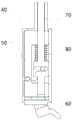
参考图1和图10所示,在一些实施例中,电磁驱动机构包括第二推杆100和第一电磁铁90,第二推杆100由导磁材料制成,第一电磁铁90被配置为得电时产生使第二推杆100向靠近第二锁止部20的方向运动的电磁力,以通过第二推杆100驱动第二锁止部20从第一位置切换至第二位置;其中,第一推杆70位于第二推杆100的远离第二锁止部20的一端,第一推杆70通过第二推杆100驱动第二锁止部20从第一位置向第二位置切换。1 and 10, in some embodiments, the electromagnetic drive mechanism includes a
在上述实施例中,固定件50被配置为安装于第二门2,转动件60可转动地连接于固定件50,第一推杆70的两端与分别与转动件60和第二推杆100可活动地连接,转动件60被配置为相对于固定件50转动使第一推杆70相对于固定件50平移以驱动第二推杆100靠近或远离第二锁止部20。In the above embodiment, the fixing
基于上述设置,本发明既可以单独通过第二推杆100和第一电磁铁90实现第二门2相对于第一门1的解锁,又可以通过机械驱动机构和第二推杆100的配合实现第二门2相对于第一门1的解锁,一方面使门锁的解锁功能便于与电控系统结合,以实现对门锁的电控设计,使门锁的操控可通过软件来执行,利于对其进行更新和优化,另一方面也能够有效保障门锁功能的可靠性,例如在断电情况下可以通过机械驱动机构和第二推杆100的配合来实现解锁。Based on the above settings, the present invention can realize the unlocking of the
参考图1和图12所示,在一些实施例中,门锁还包括第二壳体40,第二壳体40用于与第二门2连接,第二锁止部20可动地安装于第二壳体40内,固定件50设置于第二壳体40内,第二壳体40设有开口;转动件60包括从开口伸出的持握部61,以通过驱动持握部61使转动件60相对于固定件50转动。1 and 12, in some embodiments, the door lock further includes a
参考图7所示,转动件60的持握部61被设计成易于持握的结构,以便于对其进行推动或者拉动,参考图12中所示的方向,第二壳体40的下方设有开口,持握部61从开口伸出,则无论第二壳体40安装的方位或位置如何,均可以通过伸出的持握部61来控制机械驱动机构的动作以,操作简便。Referring to FIG. 7 , the
参考图4、图6、图7和图12所示,在一些实施例中,固定件50设有第一安装槽50a,第一推杆70设有第二安装槽70a,转动件60包括第一连接杆62和第二连接杆63,第一连接杆62可转动地设置于第一安装槽50a中,第二连接杆63可转动且在垂直于第二连接杆63的转动轴线的方向沿第二安装槽70a的槽壁可滑动地设置于第二安装槽70a中。Referring to Fig. 4, Fig. 6, Fig. 7 and Fig. 12, in some embodiments, the fixing
在上述实施例中,第二壳体40包括用于安装固定件50的容纳腔,该容纳腔的形状与固定件50的外轮廓相适应,从而使固定件50相对于第二壳体40的位置保持不变。在第一连接杆62相对于第一安装槽50a转动时,第二连接杆63相对于第二安装槽70a转动以及滑动,参考图4a和图4b所示,第二连接杆63在第二安装槽70a内的位置发生变化,从而使得第一推杆70相对于第二壳体40和固定件50发生平移。In the above embodiment, the
参考图1和图4所示,在一些实施例中,固定件50上设有滑道,第一推杆70与滑道滑动配合。Referring to FIG. 1 and FIG. 4 , in some embodiments, a sliding track is provided on the fixing
通过在固定件50上设置与第一推杆70配合的滑道,能够对第一推杆70的运动起到引导作用,保证第一推杆70相对于固定件50的滑动的稳定性。By arranging on the fixing
在一些实施例中,驱动装置还包括第一复位机构,第一复位机构被配置为向第一推杆70施加使其趋于远离第二锁止部20的力。In some embodiments, the driving device further includes a first reset mechanism configured to apply a force to the
通过设置第一复位机构,可以在无需人工操作的情况下使第一推杆70向远离第二锁止部20的方向移动,从而使第二锁止部20能够进一步从第二位置切换到第一位置,进而实现第二门2相对于第一门1的锁止。By providing the first reset mechanism, the
参考图6、图9和图12所示,在一些实施例中,固定件50的靠近第二锁止部20的一端包括第一凸缘部51,第一推杆70的远离第二锁止部20的一端包括第二凸缘部71,第一凸缘部51位于第二锁止部20与第二凸缘部71之间,第一复位机构包括第一复位弹簧80,第一复位弹簧80设置于第一凸缘部51与第二凸缘部71之间,第一复位弹簧80被配置向第二凸缘部71施加使其趋于远离第二锁止部20的力。6, FIG. 9 and FIG. 12, in some embodiments, the end of the fixing
在上述实施例中,当第一推杆70向靠近第二锁止部20的方向移动时,第二凸缘部71与第一凸缘部51之间的距离变小,从而使第一复位弹簧80被压缩而产生沿其轴向的弹力,参考图12中的方向,第二凸缘部71受到第一复位弹簧80施加的竖直向下的力,即是使第二凸缘部71趋于远离第二锁止部20的力。In the above embodiment, when the
在另一些实施例中,第一复位机构包括具有弹性的部件。In some other embodiments, the first reset mechanism includes an elastic component.
参考图12所示,在一些实施例中,固定件50上设有滑道,第一推杆70与滑道滑动配合,滑道包括设置于第一凸缘部51的第一通孔51a,第一推杆70穿设于第一通孔51a中,第一复位弹簧80套设于第一推杆70的位于第一凸缘部51与第二凸缘部71之间的杆段上。Referring to FIG. 12 , in some embodiments, a slideway is provided on the fixing
通过第一凸缘部51、第二凸缘部71、第一推杆70的位于第一凸缘部51与第二凸缘部71之间的杆段的配合,起到了对第一复位弹簧80的限位作用,从而保证了第一复位弹簧80的安装稳定性和工作可靠性。Through the cooperation of the
参考图6和图12所示,在一些实施例中,固定件50的远离第二锁止部20的一端包括第三凸缘部52,滑道包括设置于第三凸缘部52的第二通孔52a,第一推杆70的远离第二锁止部20的端部穿设于第二通孔52a中,第二凸缘部71位于第一凸缘部51与第三凸缘部52之间。Referring to FIG. 6 and FIG. 12 , in some embodiments, the end of the fixing
通过上述实施例中的设置,使固定件50和第一推杆70之间实现了紧密的配合,不仅保证了机械驱动机构各部件之间的装配稳定性,也有助于减小门锁的整体体积,节约空间,从而提高门锁相对于不同门的结构的适应性。Through the settings in the above-mentioned embodiments, a close fit is achieved between the fixing
参考图7和图12所示,在一些实施例中,转动件60包括第一连接杆62、第二连接杆63和两个支臂64,第一连接杆62和第二连接杆63分别连接于两个支臂64之间,第一连接杆62可转动地连接于固定件50,第二连接杆63与第一推杆70的第二凸缘部71可转动且沿垂直于第二连接杆63的转动方向可平移地活动连接,第三凸缘部52位于两个支臂64之间。7 and 12, in some embodiments, the rotating
参考图7所示,两个支臂64为板状结构,两个支臂64形成用于容纳第三凸缘部52的空间,通过第一安装槽50a、第二安装槽70a、第一连接杆62、第二连接杆63、两个支臂64、第三凸缘部52等部件之间的配合,使得固定件50与转动件60之间实现了紧密的配合,不仅保证了机械驱动机构各部件之间的装配稳定性,也有助于减小门锁的整体体积,节约空间,从而提高门锁相对于不同门的结构的适应性。Referring to Fig. 7, the two
在一些实施例中,电磁驱动机构被配置为在得电时驱动第二锁止部20从第一位置切换至第二位置。In some embodiments, the electromagnetic driving mechanism is configured to drive the
基于上述设置,可以通过给电磁驱动机构供电以使第二门2相对于第一门1解锁,操作简单快捷。Based on the above configuration, the
参考图2所示,在一些实施例中,电磁驱动机构包括第一电磁铁90和第二推杆100,第二推杆100由导磁材料制成,第一电磁铁90被配置为得电时产生使第二推杆100向靠近第二锁止部20的方向运动的电磁力,以通过第二推杆100驱动第二锁止部20从第一位置切换至第二位置。2, in some embodiments, the electromagnetic drive mechanism includes a
在上述实施例中,第一电磁铁90为中空结构,第二推杆100穿设于第一电磁铁90中,具体参考图2a所示,在第一电磁铁90失电时,第二推杆100处于初始位置,此时第二推杆100与第二锁止部20不接触,第二锁止部20处于第一位置;参考图2b所示,在第一电磁铁90得电时,由于电磁力的作用,第二推杆100相对于第一电磁铁90伸出并推动第二锁止部20运动以使第二锁止部20从第一位置切换至第二位置。In the above embodiment, the
参考图8所示,在另一些实施例中,电磁驱动机构为推拉式电磁铁,该推拉式电磁铁包括第一电磁铁90和第二推杆100,第一电磁铁90为中空结构,第二推杆100穿设于第一电磁铁90中,推拉式电磁铁具有体积小、使用方便的优点,在生产过程中可根据实际需求选用不同型号规格的推拉式电磁铁。Referring to Fig. 8, in some other embodiments, the electromagnetic drive mechanism is a push-pull electromagnet, which includes a
参考图1和图10所示,在一些实施例中,驱动装置包括机械驱动机构和电磁驱动机构,其中,机械驱动机构包括固定件50、转动件60和第一推杆70,电磁驱动机构包括第一电磁铁90和第二推杆100,第一电磁铁90被配置为得电时产生使第二推杆100向靠近第二锁止部20的方向运动的电磁力。Referring to Fig. 1 and Fig. 10, in some embodiments, the drive device includes a mechanical drive mechanism and an electromagnetic drive mechanism, wherein the mechanical drive mechanism includes a fixed
在上述实施例中,固定件50设置于第二壳体40内,转动件60可转动地连接于固定件50,第一推杆70的两端与分别与转动件60和第二推杆100可活动地连接,转动件60被配置为相对于固定件50转动使第一推杆70相对于固定件50平移以驱动第二推杆100靠近或远离第二锁止部20。In the above embodiment, the fixing
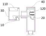
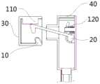
参考图3所示,在一些实施例中,电磁驱动机构包括第二电磁铁110,第二锁止部20由导磁材料制成,第二电磁铁110被配置为在得电时产生吸附第二锁止部20的电磁力,以驱动第二锁止部20从第一位置切换至第二位置。Referring to FIG. 3 , in some embodiments, the electromagnetic drive mechanism includes a
在上述实施例中,第二电磁铁110安装于第一壳体30内,且第二锁止部20的第二端位于第二电磁铁110与第一锁止部10之间,具体参考图3a所示,在第二电磁铁110失电时,第二电磁铁110与第二锁止部20不接触,第二锁止部20处于第一位置;参考图3b所示,在第二电磁铁110得电时,由于电磁力的作用,第二电磁铁110对第二锁止部20产生吸力,使得第二锁止部20的第二端被吸附到第二电磁铁110上,从而使第二锁止部20从第一位置切换至第二位置。In the above embodiment, the
参考图11和图12所示,在一些实施例中,驱动装置包括机械驱动机构和电磁驱动机构,其中,机械驱动机构包括固定件50、转动件60和第一推杆70,电磁驱动机构包括第二电磁铁110,第二锁止部20由导磁材料制成。Referring to Fig. 11 and Fig. 12, in some embodiments, the drive device includes a mechanical drive mechanism and an electromagnetic drive mechanism, wherein the mechanical drive mechanism includes a fixed
在上述实施例中,固定件50设置于第二壳体40内,转动件60可转动地连接于固定件50,第一推杆70与转动件60可活动地连接,转动件60被配置为相对于固定件50转动使第一推杆70相对于固定件50平移以靠近或远离第二锁止部20,第二电磁铁110安装于第一壳体30内,且第二锁止部20的第二端位于第二电磁铁110与第一锁止部10之间。In the above embodiment, the fixing
在一些实施例中,驱动装置还包括第二复位机构,第二复位机构被配置为向第二锁止部20施加使其趋于向第一位置切换的力。In some embodiments, the driving device further includes a second reset mechanism configured to apply a force to the
通过设置第二复位机构,可以在无需人工操作的情况下使第二锁止部20向第一位置切换,进而实现第二门2相对于第一门1的锁止。By providing the second reset mechanism, the
参考图1、图2和图3所示,在一些实施例中,门锁包括第二壳体40,第二壳体40用于与第二门2连接,第二锁止部20可动地安装于第二壳体40内;第二复位机构包括第二复位弹簧120,第二复位弹簧120设置于第二锁止部20与第二壳体40之间。Referring to Fig. 1, Fig. 2 and Fig. 3, in some embodiments, the door lock includes a
通过将第二复位弹簧120设置于第二锁止部20与第二壳体40之间,具体参考图2a和图2b所示,图2a中第二锁止部20处于第一位置时,图2b中第二锁止部20处于第二位置时,相比于图2a中所示的第二复位弹簧120的状态,图2b中所示的第二复位弹簧120被进一步压缩,因此产生向图2a中的状态恢复的趋势,同时向第二锁止部20施加沿第二复位弹簧120的轴向的弹力,即第二锁止部20受到使其趋于向第一位置切换的力。By disposing the
在另一些实施例中,第二复位机构包括具有弹性的部件。In some other embodiments, the second reset mechanism includes an elastic component.
参考图5和图10所示,在一些实施例中,第二锁止部20包括锁止部本体21和设置于锁止部本体21的止挡部22,止挡部22内设有避让孔23,第二壳体40上设有朝向止挡部22一侧凸出并伸入避让孔23内的安装柱41,第二复位弹簧120套设于安装柱41上,第二复位弹簧120的两端分别抵靠在止挡部22和第二壳体40上,第二复位弹簧120被配置为向止挡部22施加使其趋于远离第二壳体40的设有安装柱41的位置的力。Referring to Fig. 5 and Fig. 10, in some embodiments, the
参考图2和图3所示,可以看出,当第二锁止部20不处于第一位置时,止挡部22与第二壳体40之间的距离始终小于第二锁止部20处于第一位置时止挡部22与第二壳体40之间的距离,即第二复位弹簧120始终处于被压缩状态,因此产生沿其轴向的弹力,从而驱动止挡部22向远离第二壳体40的设有安装柱41的位置的方向移动,进而驱动第二锁止部20向第一位置切换。2 and 3, it can be seen that when the
在上述实施例中,第二复位弹簧120套设于安装柱41上,第二复位弹簧120设置于止挡部22与第二壳体40之间且两端分别抵靠止挡部22和第二壳体,即止挡部22、第二壳体40、安装柱41起到了对第一复位弹簧80的限位作用,从而保证了第二复位弹簧120的安装稳定性和工作可靠性。In the above embodiment, the
下面对本发明门锁的一个实施例的具体结构进行说明:The specific structure of an embodiment of the door lock of the present invention is described below:
参考图1和图13所示,在本实施例中,门锁包括第一锁止部10、第二锁止部20、第一壳体30、第二壳体40、固定件50、转动件60、第一推杆70、第一复位弹簧80、推拉式电磁铁和第二复位弹簧120,推拉式电磁铁包括第一电磁铁90和第二推杆100,第一锁止部10安装于第一壳体30内,固定件50、转动件60、第一推杆70、第一复位弹簧80、推拉式电磁铁和第二复位弹簧120均设置于第二壳体40内。1 and 13, in this embodiment, the door lock includes a
第二壳体40包括第一壳盖40a、第一壳身40b、第二壳盖40c、第二壳身40d和导管40e,锁钩设置于第一壳盖40a和第一壳身40b围成的空间内,第二锁止部20包括锁止部本体21和设置于锁止部本体21的止挡部22,止挡部22内设有避让孔23,第一壳盖40a上设有朝向止挡部22一侧凸出并伸入避让孔23内的安装柱41,第二复位弹簧120套设于安装柱41上,第二复位弹簧120的两端分别抵靠在止挡部22和第一壳盖40a上,第一壳盖40a和第一壳身40b上分别设有用于固定第二锁止部20的第一端的第一固定部和第二固定部,第二锁止部20的第二端被配置为伸入第一壳体30的内部空间并与第一锁止部10配合以实现门锁的锁止功能。The
固定件50设置于第二壳盖40c和第二壳身40d围成的空间内,转动件60可转动地连接于固定件50,且转动件60包括突出于该空间的持握部61,持握部61被设计成易于持握的结构,第一推杆70设置于导管40e内,第一推杆70的两端与分别与转动件60和第二推杆100可活动地连接。The fixing
参考图6、图7、图9和图12所示,固定件50的靠近第二锁止部20的一端包括第一凸缘部51,第一推杆70的远离第二锁止部20的一端包括第二凸缘部71,固定件50的远离第二锁止部20的一端包括第三凸缘部52,第一凸缘部51位于第二锁止部20与第二凸缘部71之间,第一复位弹簧80套设于第一推杆70的位于第一凸缘部51与第二凸缘部71之间的杆段上。6, FIG. 7, FIG. 9 and FIG. 12, one end of the fixing
固定件50上设有滑道,第一推杆70与滑道滑动配合,滑道包括设置于第一凸缘部51的第一通孔51a和设置于第三凸缘部52的第二通孔52a,第一推杆70穿设于第一通孔51a和第二通孔52a中,第二凸缘部71位于第一凸缘部51与第三凸缘部52之间。The fixing
固定件50设有第一安装槽50a,第二凸缘部71设有第二安装槽70a,转动件60还包括第一连接杆62、第二连接杆63和两个支臂64,两个支臂64为板状结构,第一连接杆62和第二连接杆63分别连接于两个支臂64之间,第一连接杆62可转动地设置于第一安装槽50a中,第二连接杆63可转动在垂直于第二连接杆63的转动轴线的方向沿第二安装槽70a的槽壁可滑动地设置于第二安装槽70a中,第三凸缘部52设置于两个支臂64之间。The fixing
通过上述设置,本发明门锁能够实现手动解锁/锁止、电动解锁/锁止的功能。Through the above settings, the door lock of the present invention can realize the functions of manual unlocking/locking and electric unlocking/locking.
在本实施例中,第一锁止部10为安装于第一壳体30的内壁上的凸起部,第二锁止部20为锁钩,本发明门锁沿竖直方向布置,即第一推杆70的轴向为竖直方向。In this embodiment, the first locking
具体的,手动解锁/锁止的实现过程如下:参考图1所示方向,通过手动拉动持握部61使得转动件60旋转角度15°左右,此时第一推杆70向上移动4mm,进而推动推拉式电磁铁的第二推杆100向上运动从而将钩锁顶起,钩锁顺时针转动并脱离凸起部,即完成门锁的解锁动作,松手后由于重力的作用以及钩锁处的第二复位弹簧120的作用,使得锁钩逆时针转动并钩挂凸起部,即完成门锁的锁止动作,同时第一推杆70处的第一复位弹簧80驱动第一推杆70向下移动使得转动件60完成复位。Specifically, the realization process of manual unlocking/locking is as follows: referring to the direction shown in FIG. The
具体的,电动解锁/锁止的实现过程如下:参考图1所示方向,推拉式电磁铁失电时第二推杆100为缩进状态,得电后由于电磁力的作用第二推杆100则会实现相对于第一电磁铁90伸出,即通电时第二推杆100向上顶出,将锁钩顶起完成解锁,断电时第二推杆100又重新缩回,锁钩在重力与第二复位弹簧120的作用下复位并完成锁定。因此通过控制推拉式电磁铁失电/得电便可以实现门锁的锁止/解锁动作。Specifically, the realization process of the electric unlocking/locking is as follows: Referring to the direction shown in FIG. Then it will be realized to stretch out relative to the
通过对本发明门锁的多个实施例的说明,可以看到本发明门锁至少具备以下优点:Through the description of multiple embodiments of the door lock of the present invention, it can be seen that the door lock of the present invention has at least the following advantages:
1、通过第一锁止部和第二锁止部的配合/解除配合实现第二门相对于第一门的锁止/解锁,则在第二门相对于第一门锁止时,打开或者关闭第一门不会导致第二门的异常打开,在第二门相对于第一门解锁时,打开或者关闭第二门的动作也不会对第一门的开闭状态造成影响,从而保障第一门和第二门的工作可靠性,大大提升了用户体验。1. The locking/unlocking of the second door relative to the first door is realized through the cooperation/disengagement of the first locking part and the second locking part, then when the second door is locked relative to the first door, open or Closing the first door will not lead to abnormal opening of the second door. When the second door is unlocked relative to the first door, the action of opening or closing the second door will not affect the opening and closing state of the first door, thereby ensuring The working reliability of the first door and the second door greatly improves the user experience.
2、设置用于控制第一锁止部和第二锁止部之间的配合关系的驱动装置,使得通过控制驱动装置便可以实现对第二门相对于第一门的锁止和解锁状态的控制,操作方便。2. A driving device is provided for controlling the cooperation relationship between the first locking part and the second locking part, so that the locking and unlocking state of the second door relative to the first door can be realized by controlling the driving device. Control, easy to operate.
3、采用电控和机械结构相结合的设计思路,实现了能够电动解锁的同时还可以手动解锁,电控的设置使门锁的操控可通过软件来执行,利于对其进行更新和优化,机械结构则保障了门锁功能的可靠性,例如在断电或是电控设备故障的情况下可以通过机械驱动机构来实现锁止和解锁;并且相比于相关技术中单纯使用门封条或纯电磁式门锁来实现门体结构的锁止的方式,本发明门锁的可靠性大大提高。3. Adopting the design idea of combining electric control and mechanical structure, it can realize electric unlocking and manual unlocking at the same time. The setting of electric control enables the control of the door lock to be performed by software, which is beneficial to update and optimize it. The structure guarantees the reliability of the door lock function. For example, in the case of power failure or electronic control equipment failure, the locking and unlocking can be realized through the mechanical drive mechanism; The locking mode of the door body structure is realized by using a type door lock, and the reliability of the door lock of the present invention is greatly improved.
4、设置了分别用于与第一门连接的第一壳体和用于与第二门连接的第二壳体,能够在不影响门锁、第一门和第二门各自的结构的情况下实现门锁相对于第一门和第二门的装拆,便于进行安装和后续维护,同时也便于将门锁的各个部件进行集成式布置,提高门锁的整体性,从而可有效扩大本发明门锁的适用范围。4. The first housing for connecting with the first door and the second housing for connecting with the second door are provided respectively, so that the respective structures of the door lock, the first door and the second door can be The assembly and disassembly of the door lock relative to the first door and the second door is realized, which is convenient for installation and follow-up maintenance, and also facilitates the integrated arrangement of various parts of the door lock to improve the integrity of the door lock, thereby effectively expanding the present invention The scope of application of the door lock.
基于上述的门锁,本发明还提出一种叠门冰箱,该叠门冰箱包括上述门锁、第一门1和与第一门1平行的第二门2,参考图14所示,门锁的第一锁止部10安装于第一门1,门锁的第二锁止部20安装于第二门2。Based on the above door lock, the present invention also proposes a folding door refrigerator, which includes the above door lock, the
上述各个实施例中门锁所具有的积极技术效果同样适用于叠门冰箱,这里不再赘述。The positive technical effects of the door locks in the above embodiments are also applicable to folding door refrigerators, and will not be repeated here.
最后应当说明的是:以上实施例仅用以说明本发明的技术方案而非对其限制;尽管参照较佳实施例对本发明进行了详细的说明,所属领域的普通技术人员应当理解:在不脱离本发明原理的前提下,依然可以对本发明的具体实施方式进行修改或者对部分技术特征进行等同替换,这些修改和等同替换均应涵盖在本发明请求保护的技术方案范围当中。Finally, it should be noted that: the above embodiments are only used to illustrate the technical solutions of the present invention and not to limit them; although the present invention has been described in detail with reference to the preferred embodiments, those of ordinary skill in the art should understand that: without departing from Under the premise of the principles of the present invention, it is still possible to modify the specific embodiments of the present invention or perform equivalent replacements on some technical features, and these modifications and equivalent replacements should be covered by the scope of the technical solutions claimed in the present invention.
Claims (21)
Priority Applications (1)
| Application Number | Priority Date | Filing Date | Title |
|---|---|---|---|
| CN202211555744.0ACN115977475A (en) | 2022-12-06 | 2022-12-06 | Door locks and folding door refrigerators |
Applications Claiming Priority (1)
| Application Number | Priority Date | Filing Date | Title |
|---|---|---|---|
| CN202211555744.0ACN115977475A (en) | 2022-12-06 | 2022-12-06 | Door locks and folding door refrigerators |
Publications (1)
| Publication Number | Publication Date |
|---|---|
| CN115977475Atrue CN115977475A (en) | 2023-04-18 |
Family
ID=85972965
Family Applications (1)
| Application Number | Title | Priority Date | Filing Date |
|---|---|---|---|
| CN202211555744.0APendingCN115977475A (en) | 2022-12-06 | 2022-12-06 | Door locks and folding door refrigerators |
Country Status (1)
| Country | Link |
|---|---|
| CN (1) | CN115977475A (en) |
Cited By (1)
| Publication number | Priority date | Publication date | Assignee | Title |
|---|---|---|---|---|
| CN116624029A (en)* | 2023-05-31 | 2023-08-22 | 广东美的厨房电器制造有限公司 | Door assembly of cooking utensil and cooking utensil |
Citations (7)
| Publication number | Priority date | Publication date | Assignee | Title |
|---|---|---|---|---|
| KR970070903A (en)* | 1996-04-04 | 1997-11-07 | 김광호 | Door locking device of refrigerator |
| CN202108330U (en)* | 2011-05-27 | 2012-01-11 | 罗作鑫 | Prying-prevention safety door lock |
| CN104864658A (en)* | 2014-02-21 | 2015-08-26 | Lg电子株式会社 | Refrigerator |
| CN105696874A (en)* | 2016-01-29 | 2016-06-22 | 海信(山东)冰箱有限公司 | Self-locking device for door-in-door refrigerator and door-in-door refrigerator |
| CN112031553A (en)* | 2019-06-04 | 2020-12-04 | 博西华电器(江苏)有限公司 | Refrigerator and door lock for refrigerator |
| CN114183972A (en)* | 2020-09-15 | 2022-03-15 | 青岛海尔电冰箱有限公司 | Refrigerator with a door |
| CN218953045U (en)* | 2022-12-06 | 2023-05-02 | 珠海格力电器股份有限公司 | Door lock and refrigerator with folding door |
- 2022
- 2022-12-06CNCN202211555744.0Apatent/CN115977475A/enactivePending
Patent Citations (7)
| Publication number | Priority date | Publication date | Assignee | Title |
|---|---|---|---|---|
| KR970070903A (en)* | 1996-04-04 | 1997-11-07 | 김광호 | Door locking device of refrigerator |
| CN202108330U (en)* | 2011-05-27 | 2012-01-11 | 罗作鑫 | Prying-prevention safety door lock |
| CN104864658A (en)* | 2014-02-21 | 2015-08-26 | Lg电子株式会社 | Refrigerator |
| CN105696874A (en)* | 2016-01-29 | 2016-06-22 | 海信(山东)冰箱有限公司 | Self-locking device for door-in-door refrigerator and door-in-door refrigerator |
| CN112031553A (en)* | 2019-06-04 | 2020-12-04 | 博西华电器(江苏)有限公司 | Refrigerator and door lock for refrigerator |
| CN114183972A (en)* | 2020-09-15 | 2022-03-15 | 青岛海尔电冰箱有限公司 | Refrigerator with a door |
| CN218953045U (en)* | 2022-12-06 | 2023-05-02 | 珠海格力电器股份有限公司 | Door lock and refrigerator with folding door |
Cited By (1)
| Publication number | Priority date | Publication date | Assignee | Title |
|---|---|---|---|---|
| CN116624029A (en)* | 2023-05-31 | 2023-08-22 | 广东美的厨房电器制造有限公司 | Door assembly of cooking utensil and cooking utensil |
Similar Documents
| Publication | Publication Date | Title |
|---|---|---|
| JP2019183492A (en) | Electric lock | |
| US9790708B2 (en) | Magnetic latch | |
| US8702133B2 (en) | Bi-stable actuator for electronic lock | |
| CN115977475A (en) | Door locks and folding door refrigerators | |
| CN112922461B (en) | Locking mechanism | |
| JPH02157376A (en) | Lock | |
| CN218953045U (en) | Door lock and refrigerator with folding door | |
| CN206987566U (en) | Unlock trigger mechanism, electronic lock and platform door system | |
| KR101666764B1 (en) | Push-pull type door lock | |
| WO2021058253A1 (en) | Lock device and system | |
| CN212743677U (en) | Control device of car door lock body | |
| CN215859542U (en) | Lock and cabinet | |
| JP2008133656A (en) | Electric lock | |
| CN111809989B (en) | Door lock control device | |
| EP2395286B1 (en) | High-frequency heating device | |
| CN222146078U (en) | Rotary isolating switch capable of being far Cheng Guasuo | |
| EP4293184B1 (en) | Lock device | |
| CN113972109A (en) | Clutch transmission assembly and circuit breaker | |
| CN101634203A (en) | Electromagnetic lock structure | |
| CN222637082U (en) | Electric mechanism of change-over switch and change-over switch | |
| US20250129645A1 (en) | Door lock assembly | |
| KR102000975B1 (en) | Digital doorlock of push-full type | |
| KR102593017B1 (en) | Locking device for windows | |
| CN215553691U (en) | Faucet lock for electric vehicle | |
| JP5058868B2 (en) | Push-pull electric lock |
Legal Events
| Date | Code | Title | Description |
|---|---|---|---|
| PB01 | Publication | ||
| PB01 | Publication | ||
| SE01 | Entry into force of request for substantive examination | ||
| SE01 | Entry into force of request for substantive examination |