CN115963113A - Glue detection method and system for workpiece glue tank - Google Patents
Glue detection method and system for workpiece glue tankDownload PDFInfo
- Publication number
- CN115963113A CN115963113ACN202211725082.7ACN202211725082ACN115963113ACN 115963113 ACN115963113 ACN 115963113ACN 202211725082 ACN202211725082 ACN 202211725082ACN 115963113 ACN115963113 ACN 115963113A
- Authority
- CN
- China
- Prior art keywords
- glue
- colloid
- data
- workpiece
- detection method
- Prior art date
- Legal status (The legal status is an assumption and is not a legal conclusion. Google has not performed a legal analysis and makes no representation as to the accuracy of the status listed.)
- Pending
Links
Images


Landscapes
- Length Measuring Devices By Optical Means (AREA)
- Investigating Materials By The Use Of Optical Means Adapted For Particular Applications (AREA)
Abstract
Translated fromChineseDescription
Translated fromChinese技术领域technical field
本发明属于汽车零部件技术领域,特别涉及一种车灯工件胶槽涂胶检测方法和系统。The invention belongs to the technical field of auto parts, and in particular relates to a method and system for detecting glue coating in a glue tank of a car lamp workpiece.
背景技术Background technique
汽车车灯后壳胶槽的胶体通常对工件起到密封作用,在涂胶过程中容易出少胶、缺胶、溢胶等问题,由于胶体在后壳胶槽凹槽内,凹槽的形状是曲线且凹槽开口方向不一致,给检测增加了难度。The colloid in the rubber groove of the rear shell of the car lamp usually plays a sealing role on the workpiece. During the glue application process, problems such as insufficient glue, glue shortage, and overflowing glue are easy to occur. Since the colloid is in the groove of the rear shell glue groove, the shape of the groove It is a curve and the opening direction of the groove is inconsistent, which increases the difficulty of detection.
现有的方案中,包括采用2D视觉进行检测方法。通过精细的打光,呈现出胶体缺陷,将涂胶正常和涂胶有缺陷的2维图像区分开,通过二维处理算法分析出缺陷位置。但是,采用2D视觉进行检测时,由于产品和胶体表面反光等影响,对光源打光的要求极高,易受环境影响造成误判。另外2D视觉无法获得高度信息,对于少量缺胶溢胶不易识别。Existing solutions include detection methods using 2D vision. Through fine lighting, the colloidal defects are presented, and the 2D images with normal gluing and defective gluing are distinguished, and the location of the defect is analyzed through a 2D processing algorithm. However, when 2D vision is used for inspection, due to the influence of product and colloid surface reflection, etc., the requirements for lighting the light source are extremely high, and it is easy to be misjudged by environmental influences. In addition, 2D vision cannot obtain height information, and it is difficult to identify a small amount of missing glue and overflowing glue.
现有方案中,还包括采用双目视觉进行检测方法。通过分段拍摄,呈现涂胶部位的分段三维图像,在三维图像上进行胶体高度宽度的测量,判断胶体缺陷。但是,采用双目视觉分段测量胶体高度的方法,相机光源占用空间较大,对于狭窄拐角处存在空间干涉,无法进行测量;另外胶槽窄长,分段过大,检测精度不够,分段过小,效率太低。In the existing scheme, a detection method using binocular vision is also included. Through segmental shooting, the segmented three-dimensional image of the glued part is presented, and the height and width of the colloid are measured on the three-dimensional image to judge the colloidal defect. However, using binocular vision to measure colloid height in segments, the camera light source takes up a lot of space, and there is spatial interference at narrow corners, making it impossible to measure; Too small and too inefficient.
发明内容Contents of the invention
本发明实施例之一,一种车灯胶槽涂胶检测的方法,该工件壳体的边缘具有胶槽,该胶槽在涂胶工艺后用于工件壳体的胶合,所述检测方法包括以下步骤:One of the embodiments of the present invention is a method for detecting the glue coating of the glue tank of the car lamp. The edge of the workpiece shell has a glue groove, and the glue groove is used for gluing the workpiece shell after the glue coating process. The detection method includes The following steps:
将激光线扫传感装置设置在机器人机械臂末端;Set the laser line-scanning sensing device at the end of the robotic arm of the robot;
驱动所述机器人机械臂沿着所述胶槽,通过激光线扫传感装置上的传感器对所述胶槽内的胶体进行扫描;Drive the robot arm along the glue groove, and scan the colloid in the glue groove through the sensor on the laser line scanning sensor device;
根据获得的胶槽内胶体的形态数据判断涂胶是否合格。According to the obtained shape data of the colloid in the glue tank, it is judged whether the glue is qualified or not.
优选的,在获得胶体的形态数据后,利用轮廓检测算法获得形态轮廓数据,根据形态轮廓数据计算获得涂胶胶体的长度、宽度和截面积,根据这些数据判断胶体是否有缺陷。Preferably, after obtaining the morphological data of the colloid, use a contour detection algorithm to obtain the morphological contour data, calculate and obtain the length, width and cross-sectional area of the glued colloid according to the morphological contour data, and judge whether the colloid is defective according to these data.
优选的,根据获得的形态轮廓数据生成胶体形态的深度图和亮度图,输入经过训练的基于深度学习的胶体缺陷判断模型,判断胶体的缺陷类型。Preferably, a depth map and a brightness map of the colloidal form are generated according to the obtained morphological profile data, and the trained colloid defect judgment model based on deep learning is input to determine the defect type of the colloid.
优选的,所述深度图是根据由形态轮廓数据生成的胶体形态的3D点云图生成的。Preferably, the depth map is generated according to the 3D point cloud image of the colloid shape generated from the shape contour data.
附图说明Description of drawings
通过参考附图阅读下文的详细描述,本发明示例性实施方式的上述以及其他目的、特征和优点将变得易于理解。在附图中,以示例性而非限制性的方式示出了本发明的若干实施方式,其中:The above and other objects, features and advantages of exemplary embodiments of the present invention will become readily understood by reading the following detailed description with reference to the accompanying drawings. In the drawings, several embodiments of the invention are shown by way of illustration and not limitation, in which:
图1根据本发明实施例之一的车灯后壳胶槽涂胶检测系统示意图。Fig. 1 is a schematic diagram of a detection system for glue coating in a glue groove of a rear cover of a car lamp according to one embodiment of the present invention.
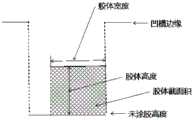
图2根据本发明实施例之一的胶体合格状态示意图。Fig. 2 is a schematic diagram of a colloid qualified state according to one embodiment of the present invention.
图3根据本发明实施例之一的胶体缺陷状态示意图。Fig. 3 is a schematic diagram of a colloid defect state according to one embodiment of the present invention.
图4根据本发明实施例之一的胶体缺陷状态示意图。Fig. 4 is a schematic diagram of a colloid defect state according to one embodiment of the present invention.
图5根据本发明实施例之一的胶体缺陷状态示意图。Fig. 5 is a schematic diagram of a colloid defect state according to one embodiment of the present invention.
图6根据本发明实施例之一的胶体形态计算示意图。Fig. 6 is a schematic diagram of colloid morphology calculation according to one embodiment of the present invention.
图7根据本发明实施例之一的胶体缺陷检测流程示意图。Fig. 7 is a schematic diagram of a colloid defect detection process according to one embodiment of the present invention.
1——胶槽,1——glue tank,
2——机器人2 - Robot
3——激光线扫传感器3——Laser line scan sensor
4——激光4 - laser
具体实施方式Detailed ways
根据一个或者多个实施例,一种车灯胶槽涂胶检测的方法。如图1所示,将激光线扫传感器装置安装在一台机器人的机械臂第六轴末端,涂胶后的汽车后壳工件放置在固定夹具上,通过仿真和示教的方式得到机器人带动激光线扫装置扫描整个凹槽的路径和姿态。机器人机械臂沿着后壳胶槽边缘凹槽的路径进行运动,带动激光线扫传感器进行扫描,扫描姿态根据凹槽开口方向确定。According to one or more embodiments, a method for detecting glue in a glue tank of a vehicle lamp. As shown in Figure 1, the laser line-scanning sensor device is installed at the end of the sixth axis of a robot’s mechanical arm, and the glued car rear shell workpiece is placed on a fixed fixture, and the robot drives the laser through simulation and teaching. The line scanning device scans the path and posture of the entire groove. The robotic arm of the robot moves along the path of the groove on the edge of the back shell rubber groove, driving the laser line scan sensor to scan, and the scanning posture is determined according to the opening direction of the groove.
在扫描过程中,会实时生成凹槽以及胶体的形貌轮廓数据(含高度以及亮度值)。利用轮廓检测算法,对轮廓线进行处理,测量涂胶区域截面积,长度宽度等,判断涂胶缺陷。当扫描完成以后,轮廓数据组合成3D的点云图和2D的亮度图,利用深度学习算法网络对深度图像和亮度图进行推理,检测涂胶缺陷。经过多重算法的结合保证涂胶缺陷都能被识别出。During the scanning process, the profile data (including height and brightness values) of the groove and the colloid will be generated in real time. Use the contour detection algorithm to process the contour line, measure the cross-sectional area, length and width of the glued area, and judge the glued defects. After the scanning is completed, the contour data is combined into a 3D point cloud image and a 2D brightness image, and the deep learning algorithm network is used to infer the depth image and brightness image to detect glue coating defects. The combination of multiple algorithms ensures that gluing defects can be identified.
如图2至图6,是胶槽内胶体各种情况的轮廓示意图,在扫描过程中,传感器会不断采集到近似的轮廓线数据,并用算法实时进行胶体截面积,高度,宽度等数据的计算,初步判断是否有涂胶缺陷。图2表示了正常涂胶的高度,图3表示了溢胶的高度。图4表示了少胶的状态。图5表示了另一种少胶的状态。图6表示了另一种少胶的状态,说明了胶体截面积与胶体高度、胶体宽度的关系。As shown in Figure 2 to Figure 6, it is a schematic diagram of the outline of various situations of colloid in the glue tank. During the scanning process, the sensor will continuously collect approximate contour line data, and use the algorithm to calculate the cross-sectional area, height, width and other data of the colloid in real time. , to preliminarily judge whether there is a glue defect. Figure 2 shows the height of normal glue application, and Figure 3 shows the height of overflow glue. Figure 4 shows the state of less glue. Figure 5 shows another state of less glue. Figure 6 shows another state of less glue, illustrating the relationship between the cross-sectional area of the glue, the height of the glue, and the width of the glue.
机器人对胶槽扫描结束以后,所有的轮廓数据积累形成3D点云图和亮度图,运用深度学习算法再次进行涂胶检测的判断,最后综合得到实际缺陷判定和位置。综合判定主要作用是通过比较深度学习检测到的缺陷位置和轮廓检测中检测到缺陷的位置差异,避免了轮廓检测中个别轮廓点丢失造成的误判,同时对于一些凹槽边缘变化较大,轮廓检测中无法捕捉凹槽边缘从而进行胶体测量的区域,运用深度学习完善这部分区域的检测。这个过程如图7所示。After the robot scans the glue tank, all the contour data are accumulated to form a 3D point cloud map and brightness map, and the deep learning algorithm is used to judge the glue coating inspection again, and finally the actual defect judgment and position are obtained comprehensively. The main function of the comprehensive judgment is to avoid the misjudgment caused by the loss of individual contour points in the contour detection by comparing the position of the defect detected by deep learning and the position of the defect detected in the contour detection. The area where the edge of the groove cannot be captured for colloid measurement in the detection, using deep learning to improve the detection of this part of the area. This process is shown in Figure 7.
本公开实施例中,采用内置图像算法模块和AI检测模块的激光线扫描传感装置,能够实现胶槽内涂胶形貌的扫描,生成亮度图、3D点云,并根据点云生成深度图。In the embodiment of the present disclosure, the laser line scanning sensing device with a built-in image algorithm module and an AI detection module can realize the scanning of the topography of the glue in the glue tank, generate a brightness map, a 3D point cloud, and generate a depth map based on the point cloud .
采用视野大小仅覆盖胶槽区域的线扫装置,按胶槽路径逐行扫描胶槽,提高了检测精度,避免了胶槽路径形状对检测效率和精度的影响The line scanning device with a field of view that only covers the area of the glue tank is used to scan the glue tank line by line according to the glue tank path, which improves the detection accuracy and avoids the influence of the shape of the glue tank path on the detection efficiency and accuracy
采用轮廓分析方法,对实时采集的胶槽内涂胶表面形貌进行分析,计算采集轮廓的截面积,并与标准值对比。The contour analysis method is used to analyze the surface morphology of the glued surface collected in the glue tank in real time, calculate the cross-sectional area of the collected contour, and compare it with the standard value.
激光线扫传感装置内置基于亮度图和深度图的缺陷检测深度学习模型。完成一次全程采集后,对生成的灰度图和深度图进行数据推理,判断缺陷及位置。The laser line scan sensing device has a built-in deep learning model for defect detection based on brightness maps and depth maps. After completing a full collection, data reasoning is performed on the generated grayscale image and depth image to determine the defect and its location.
由于单独基于灰度图的AI检测可能存在误检,对环境打光等要求较严格。而深度图具有目标物的高度信息,检测结果更准确。因此将二者结合,可有效简化现场打光调试,提高检测准确率。Since AI detection based solely on grayscale images may have false detections, the requirements for environmental lighting are strict. The depth map has the height information of the target object, and the detection result is more accurate. Therefore, combining the two can effectively simplify on-site lighting debugging and improve detection accuracy.
相对于,现有的采用2D相机采集2D图像对比的方法,以及采用3D双目相机分段测量胶体高度的方法。本发明利用线激光3D传感器测量胶体宽度高度并结合深度学习识别缺陷的方法更加稳定可靠,精度更高。本发明的有益效果包括:Compared with the existing method of using a 2D camera to collect 2D images for comparison, and the method of segmentally measuring the colloid height using a 3D binocular camera. The present invention uses a line laser 3D sensor to measure the width and height of the colloid and combines deep learning to identify defects, which is more stable and reliable, and has higher precision. The beneficial effects of the present invention include:
对车灯后壳进行凹槽类的涂胶检测,宽度方向视野仅覆盖凹槽,精度更高;Carry out glue-coating detection of grooves on the back cover of the car lamp, the field of view in the width direction only covers the grooves, and the accuracy is higher;
由于采用轮廓检测算法和深度学习算法综合判定,检测稳定性更高;Due to the comprehensive judgment of the contour detection algorithm and the deep learning algorithm, the detection stability is higher;
相比于2D机器视觉检测方法,省去了打光环节,更加便于方案的部署;Compared with the 2D machine vision inspection method, the lighting link is omitted, which is more convenient for the deployment of the solution;
对于工件上的凹槽长度没有限制,拓展性更强;There is no limit to the length of the groove on the workpiece, and the expansion is stronger;
当工件形状有变化时,仅需对机器人示教路径即可,切换自由度更高。When the shape of the workpiece changes, it is only necessary to teach the path to the robot, and the switching freedom is higher.
因此,本发明的技术方案,也适用于其他工件的细槽内涂胶类检测,或者工件槽内其他填充物的检测。Therefore, the technical solution of the present invention is also applicable to the detection of glue coating in the thin grooves of other workpieces, or the detection of other fillers in the workpiece grooves.
值得说明的是,虽然前述内容已经参考若干具体实施方式描述了本发明创造的精神和原理,但是应该理解,本发明并不限于所公开的具体实施方式,对各方面的划分也不意味着这些方面中的特征不能组合,这种划分仅是为了表述的方便。本发明旨在涵盖所附权利要求的精神和范围内所包括的各种修改和等同布置。It is worth noting that although the foregoing content has described the spirit and principle of the invention with reference to several specific embodiments, it should be understood that the present invention is not limited to the disclosed specific embodiments, and the division of various aspects does not mean that these Features within an aspect cannot be combined, this division is for convenience of presentation only. The present invention is intended to cover various modifications and equivalent arrangements included within the spirit and scope of the appended claims.
Claims (9)
Translated fromChinesePriority Applications (1)
| Application Number | Priority Date | Filing Date | Title |
|---|---|---|---|
| CN202211725082.7ACN115963113A (en) | 2022-12-30 | 2022-12-30 | Glue detection method and system for workpiece glue tank |
Applications Claiming Priority (1)
| Application Number | Priority Date | Filing Date | Title |
|---|---|---|---|
| CN202211725082.7ACN115963113A (en) | 2022-12-30 | 2022-12-30 | Glue detection method and system for workpiece glue tank |
Publications (1)
| Publication Number | Publication Date |
|---|---|
| CN115963113Atrue CN115963113A (en) | 2023-04-14 |
Family
ID=87363220
Family Applications (1)
| Application Number | Title | Priority Date | Filing Date |
|---|---|---|---|
| CN202211725082.7APendingCN115963113A (en) | 2022-12-30 | 2022-12-30 | Glue detection method and system for workpiece glue tank |
Country Status (1)
| Country | Link |
|---|---|
| CN (1) | CN115963113A (en) |
Cited By (1)
| Publication number | Priority date | Publication date | Assignee | Title |
|---|---|---|---|---|
| CN116503386A (en)* | 2023-06-25 | 2023-07-28 | 宁德时代新能源科技股份有限公司 | Method and device for detecting structural adhesive, terminal and computer readable storage medium |
Citations (5)
| Publication number | Priority date | Publication date | Assignee | Title |
|---|---|---|---|---|
| US20190197340A1 (en)* | 2016-01-15 | 2019-06-27 | Wuhan Wuda Zoyon Science And Technology Co., Ltd. | Object surface deformation feature extraction method based on line scanning three-dimensional point cloud |
| CN111665257A (en)* | 2020-07-02 | 2020-09-15 | 北京智机科技有限公司 | Glue type detection scanning system and detection method thereof |
| CN112561850A (en)* | 2019-09-26 | 2021-03-26 | 上海汽车集团股份有限公司 | Automobile gluing detection method and device and storage medium |
| CN113866171A (en)* | 2021-12-02 | 2021-12-31 | 武汉飞恩微电子有限公司 | Circuit board dispensing detection method and device and computer readable storage medium |
| CN114166846A (en)* | 2021-11-01 | 2022-03-11 | 首都航天机械有限公司 | Cold rolling section bar code of rolling up of iron and steel trade and defect detection device |
- 2022
- 2022-12-30CNCN202211725082.7Apatent/CN115963113A/enactivePending
Patent Citations (5)
| Publication number | Priority date | Publication date | Assignee | Title |
|---|---|---|---|---|
| US20190197340A1 (en)* | 2016-01-15 | 2019-06-27 | Wuhan Wuda Zoyon Science And Technology Co., Ltd. | Object surface deformation feature extraction method based on line scanning three-dimensional point cloud |
| CN112561850A (en)* | 2019-09-26 | 2021-03-26 | 上海汽车集团股份有限公司 | Automobile gluing detection method and device and storage medium |
| CN111665257A (en)* | 2020-07-02 | 2020-09-15 | 北京智机科技有限公司 | Glue type detection scanning system and detection method thereof |
| CN114166846A (en)* | 2021-11-01 | 2022-03-11 | 首都航天机械有限公司 | Cold rolling section bar code of rolling up of iron and steel trade and defect detection device |
| CN113866171A (en)* | 2021-12-02 | 2021-12-31 | 武汉飞恩微电子有限公司 | Circuit board dispensing detection method and device and computer readable storage medium |
Cited By (2)
| Publication number | Priority date | Publication date | Assignee | Title |
|---|---|---|---|---|
| CN116503386A (en)* | 2023-06-25 | 2023-07-28 | 宁德时代新能源科技股份有限公司 | Method and device for detecting structural adhesive, terminal and computer readable storage medium |
| CN116503386B (en)* | 2023-06-25 | 2023-12-01 | 宁德时代新能源科技股份有限公司 | Structural adhesive detection method, device, terminal and computer-readable storage medium |
Similar Documents
| Publication | Publication Date | Title |
|---|---|---|
| CN110095061B (en) | Vehicle form and position detection system and method based on contour scanning | |
| CN112798617B (en) | Mirror-like object defect detection device and detection method thereof | |
| CA3041590C (en) | Mobile and automated apparatus for the detection and classification of damages on the body of a vehicle | |
| US11619485B2 (en) | Hybrid 3D optical scanning system | |
| CN100483116C (en) | Method for detecting 3D defects on surface of belt material | |
| JP4894628B2 (en) | Appearance inspection method and appearance inspection apparatus | |
| JP4862765B2 (en) | Surface inspection apparatus and surface inspection method | |
| Zhang et al. | Stud pose detection based on photometric stereo and lightweight YOLOv4 | |
| CN105866129A (en) | Product surface quality online detection method based on digital projection | |
| JP5913903B2 (en) | Shape inspection method and apparatus | |
| CN116429768B (en) | A method, system, device and storage medium for detecting welding quality of sealing pins | |
| CN102297658A (en) | Three-dimensional information detection method based on dual laser | |
| CN116337871A (en) | Power battery weld joint detection method, system, equipment and storage medium | |
| CN115375608A (en) | Detection method and device, detection equipment and storage medium | |
| CN115963113A (en) | Glue detection method and system for workpiece glue tank | |
| US6906808B2 (en) | Methods and apparatus for measuring a surface contour of an object | |
| CN115375610A (en) | Detection method and device, detection equipment and storage medium | |
| Tandiya et al. | Automotive semi-specular surface defect detection system | |
| CN114608458B (en) | Device and method for detecting thickness of die attach adhesive | |
| CN108534704A (en) | Cylinder inner wall detection system based on structured light | |
| TW201617605A (en) | Defect inspection method and apparatus thereof | |
| CN118189859A (en) | Non-contact coaxiality measuring method and system | |
| Sun et al. | Precision work-piece detection and measurement combining top-down and bottom-up saliency | |
| CN209624417U (en) | Touch screen defect detecting device based on the confocal camera of line | |
| CN115468961A (en) | Wheel set tread scratch real-time detection method and system based on laser galvanometer |
Legal Events
| Date | Code | Title | Description |
|---|---|---|---|
| PB01 | Publication | ||
| PB01 | Publication | ||
| SE01 | Entry into force of request for substantive examination | ||
| SE01 | Entry into force of request for substantive examination |