CN115962688A - Laser reciprocating scanning transmitter - Google Patents
Laser reciprocating scanning transmitterDownload PDFInfo
- Publication number
- CN115962688A CN115962688ACN202211736324.2ACN202211736324ACN115962688ACN 115962688 ACN115962688 ACN 115962688ACN 202211736324 ACN202211736324 ACN 202211736324ACN 115962688 ACN115962688 ACN 115962688A
- Authority
- CN
- China
- Prior art keywords
- laser
- reflector
- light
- circular
- circular reflector
- Prior art date
- Legal status (The legal status is an assumption and is not a legal conclusion. Google has not performed a legal analysis and makes no representation as to the accuracy of the status listed.)
- Pending
Links
- 230000000903blocking effectEffects0.000description4
- 238000010586diagramMethods0.000description2
- 230000003287optical effectEffects0.000description2
- XUIMIQQOPSSXEZ-UHFFFAOYSA-NSiliconChemical compound[Si]XUIMIQQOPSSXEZ-UHFFFAOYSA-N0.000description1
- 230000003321amplificationEffects0.000description1
- 230000009286beneficial effectEffects0.000description1
- 230000005540biological transmissionEffects0.000description1
- 238000001514detection methodMethods0.000description1
- 230000000694effectsEffects0.000description1
- 238000000034methodMethods0.000description1
- 238000012986modificationMethods0.000description1
- 230000004048modificationEffects0.000description1
- 238000003199nucleic acid amplification methodMethods0.000description1
- 229910052710siliconInorganic materials0.000description1
- 239000010703siliconSubstances0.000description1
Images


Classifications
- Y—GENERAL TAGGING OF NEW TECHNOLOGICAL DEVELOPMENTS; GENERAL TAGGING OF CROSS-SECTIONAL TECHNOLOGIES SPANNING OVER SEVERAL SECTIONS OF THE IPC; TECHNICAL SUBJECTS COVERED BY FORMER USPC CROSS-REFERENCE ART COLLECTIONS [XRACs] AND DIGESTS
- Y02—TECHNOLOGIES OR APPLICATIONS FOR MITIGATION OR ADAPTATION AGAINST CLIMATE CHANGE
- Y02A—TECHNOLOGIES FOR ADAPTATION TO CLIMATE CHANGE
- Y02A90/00—Technologies having an indirect contribution to adaptation to climate change
- Y02A90/10—Information and communication technologies [ICT] supporting adaptation to climate change, e.g. for weather forecasting or climate simulation
Landscapes
- Optical Radar Systems And Details Thereof (AREA)
Abstract
Translated fromChinese
Description
Translated fromChinese技术领域technical field
本发明涉及一种激光往返扫描发射仪。The invention relates to a laser reciprocating scanning emitter.
背景技术Background technique
其中驾束制导是目标探测和跟踪系统对目标实现精确跟踪照射,并且形成指向目标的等强或等值的信号线,导弹尾部接收装置敏感出偏差等值线的大小和方位,并形成控制指令,控制导弹飞行,与指令制导不同的是指令在弹上形成,无需指令传输。Among them, the beam guidance is that the target detection and tracking system realizes precise tracking and irradiation of the target, and forms an equal-strength or equivalent signal line pointing to the target. The missile tail receiving device is sensitive to the size and orientation of the deviation contour line, and forms a control command. , to control the flight of the missile. Unlike the command guidance, the command is formed on the missile without command transmission.
发明内容Contents of the invention
为解决以上现有技术存在的问题,本发明提出一种激光往返扫描发射仪。In order to solve the above problems in the prior art, the present invention proposes a laser reciprocating scanning emitter.
本发明可通过以下技术方案予以实现:The present invention can be realized through the following technical solutions:
一种激光往返扫描发射仪,包括壳体,壳体内圆反射镜、带动圆反射镜转动的减速马达、激光器、用于给所述减速马达和激光器供电的PCB板、长方体反射镜,及2块挡光板和1块长挡光板,所述圆反射镜置于镜架上,该镜架置于所述减速马达的旋转轴上;所述激光器连接单片机,通过单片机控制所述激光器的开关,所述激光器与所述圆反射镜设在同一水平高度;所述2块挡光板和1块长挡光板间隔排列,且与所述圆反射镜所在平面平行设置,所述长方体反射镜设置在第二块挡光板上边缘处,与挡光板边缘呈80°夹角。A laser reciprocating scanning transmitter, comprising a shell, a circular reflector inside the shell, a deceleration motor that drives the circular reflector to rotate, a laser, a PCB board for powering the deceleration motor and the laser, a cuboid reflector, and 2 pieces A light baffle and a long light baffle, the circular reflector is placed on the mirror frame, and the mirror frame is placed on the rotating shaft of the deceleration motor; the laser is connected to a single-chip microcomputer, and the switch of the laser is controlled by the single-chip microcomputer, so The laser and the circular reflector are arranged at the same level; the two light baffles and one long light baffle are arranged at intervals and arranged parallel to the plane where the circular reflector is located, and the cuboid reflector is arranged on the second The edge of the block light baffle forms an angle of 80° with the edge of the light baffle.
进一步地,所述2块挡光板长15mm,1块长挡光板的长为19mm。Further, the length of the two light blocking plates is 15 mm, and the length of one long light blocking plate is 19 mm.
进一步地,所述2块挡光板、1块长挡光板与圆反射镜的横向距离为34mm。Further, the lateral distance between the two light baffles, one long light baffle and the circular mirror is 34mm.
进一步地,所述长挡光板下边缘与圆反射镜旋转中心的纵向距离为6.5mm,第一块挡光板上边缘与圆反射镜旋转中心的纵向距离为1mm,所成的通光空隙在圆反射镜的上侧。Further, the longitudinal distance between the lower edge of the long light baffle and the center of rotation of the circular reflector is 6.5 mm, the longitudinal distance between the edge of the first light baffle and the center of rotation of the circular reflector is 1 mm, and the formed light gap is within the circle the upper side of the mirror.
进一步地,第一块挡光板下边缘与反射镜旋转中心的纵向距离为14mm,第二块挡光板上边缘与圆反射镜旋转中心的纵向距离为24.4mm,所成的通光空隙在反射镜的下侧。Further, the longitudinal distance between the lower edge of the first light baffle and the center of rotation of the reflector is 14 mm, and the longitudinal distance between the edge of the second light baffle and the center of rotation of the circular reflector is 24.4 mm. the underside of the
进一步地,所述长方体反射镜长度30mm。Further, the length of the cuboid reflector is 30mm.
本发明具有以下有益效果:The present invention has the following beneficial effects:
1.能够较为精确判断偏离中心的距离;1. Able to accurately judge the distance from the center;
2.低成本地实现制导控制;2. Realize guidance and control at low cost;
3.扫描频率可以设置较低的水平。3. The scanning frequency can be set to a lower level.
附图说明Description of drawings
图1为本发明的结构示意图Fig. 1 is a structural representation of the present invention
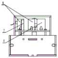
图2为本发明的内部结构图Fig. 2 is the internal structure figure of the present invention
图3为本发明的另一侧内部结构示意图Fig. 3 is another side internal structure schematic diagram of the present invention
图4为本发明的光路示意图Fig. 4 is the optical path schematic diagram of the present invention
图中1,减速马达;2,激光器固定架;3,镜架;4,激光器;5,圆反射镜;6,挡光板;7,长方体反射镜;8,长挡光板;9,PCB板In the figure 1, deceleration motor; 2, laser fixing frame; 3, mirror frame; 4, laser; 5, circular reflector; 6, light baffle; 7, cuboid reflector;
具体实施方式Detailed ways
以下通过特定的具体实施例说明本发明的实施方式,本领域的技术人员可由本说明书所揭示的内容轻易地了解本发明的其他优点及功效。The implementation of the present invention is described below through specific specific examples, and those skilled in the art can easily understand other advantages and effects of the present invention from the content disclosed in this specification.
如图1-3所示,本发明的一种激光往返扫描发射仪,包括壳体,壳体内圆反射镜5、带动圆反射镜5转动的减速马达1、激光器4(固定于激光器固定架2上)、用于给减速马达1和激光器4供电的PCB板9、长方体反射镜7,及2块挡光板6和1块长挡光板8,圆反射镜5置于镜架3上,该镜架3置于减速马达1的旋转轴上;激光器4连接单片机,通过单片机控制激光器4的开关,激光器4与圆反射镜5设在同一水平高度;2块挡光板6和1块长挡光板8间隔排列,且与圆反射镜5所在平面平行设置,长方体反射镜7设置在第二块挡光板上边缘处,与挡光板边缘呈80°夹角。As shown in Figures 1-3, a kind of laser reciprocating scanning transmitter of the present invention comprises housing, housing inner circular reflector 5, deceleration motor 1 that drives circular reflector 5 to rotate, laser 4 (fixed on laser fixture 2 Above), the PCB board 9 for powering the deceleration motor 1 and the laser 4, the cuboid reflector 7, and 2 light baffles 6 and 1 long light baffle 8, the circular reflector 5 is placed on the mirror frame 3, the mirror The frame 3 is placed on the rotating shaft of the deceleration motor 1; the laser 4 is connected to the single-chip microcomputer, and the switch of the laser 4 is controlled by the single-chip microcomputer, and the laser 4 and the circular mirror 5 are set at the same level; 2 light blocking plates 6 and 1 long light blocking plate 8 Arranged at intervals, and arranged parallel to the plane where the circular reflector 5 is located, the cuboid reflector 7 is arranged at the edge of the second light-shielding plate, forming an angle of 80° with the edge of the light-shielding plate.
其中,所述2块挡光板长15mm,1块长挡光板的长为19mm;2块挡光板、1块长挡光板与圆反射镜的横向距离为34mm;长挡光板下边缘与圆反射镜旋转中心的纵向距离为6.5mm,第一块挡光板上边缘与圆反射镜旋转中心的纵向距离为1mm,所成的通光空隙在圆反射镜的上侧;第一块挡光板下边缘与反射镜旋转中心的纵向距离为14mm,第二块挡光板上边缘与圆反射镜旋转中心的纵向距离为24.4mm,所成的通光空隙在反射镜的下侧;长方体反射镜长度30mm。Wherein, the length of said 2 light baffles is 15mm, and the length of 1 long light baffle is 19mm; the lateral distance between 2 light baffles, 1 long light baffle and the circular reflector is 34mm; the lower edge of the long light baffle and the circular reflector The longitudinal distance of the center of rotation is 6.5 mm, the longitudinal distance between the edge of the first light baffle and the center of rotation of the circular reflector is 1 mm, and the formed light gap is on the upper side of the circular reflector; the lower edge of the first light baffle and The longitudinal distance between the center of rotation of the reflector is 14mm, the longitudinal distance between the edge of the second light baffle plate and the center of rotation of the circular reflector is 24.4mm, and the formed light gap is on the lower side of the reflector; the length of the cuboid reflector is 30mm.
工作原理:working principle:
发射端:激光器常亮,电机带动圆反射镜旋转,经特制光路反射后实现来回扫描。Transmitter: The laser is always on, and the motor drives the circular mirror to rotate, and scans back and forth after being reflected by a special optical path.
反射点为圆反射镜几何中心,圆反射镜逆时针旋转,至a位置(图4所示)时反射光通过缝隙,对目标区域进行从右至左的扫描。此后反射光被遮挡,旋转至b位置时旋转圆反射镜反射光受长方体反射镜二次反射,实现对目标区域从左至右的扫描。The reflection point is the geometric center of the circular mirror. The circular mirror rotates counterclockwise. When the circular mirror reaches position a (as shown in Figure 4), the reflected light passes through the slit and scans the target area from right to left. Afterwards, the reflected light is blocked, and when it is rotated to position b, the reflected light of the rotating circular mirror is reflected twice by the cuboid mirror to realize scanning of the target area from left to right.
接收端:接收端硅光二极管受激光照射时输出微弱电压,经二级放大后输入单片机。单片机记录每两次接收到信号的时间间隔,根据其数值所处范围判断自身所处位置区域,发出控制指令,使电机带动接收装置向中间区域移动,直至回正。Receiving end: When the silicon photodiode at the receiving end is irradiated by laser light, it outputs a weak voltage, which is input to the single-chip microcomputer after secondary amplification. The single-chip microcomputer records the time interval of receiving the signal every two times, judges the area where it is located according to the range of its value, and issues a control command to make the motor drive the receiving device to move to the middle area until it returns to normal.
电机带动圆反射镜旋转,两次扫描之间时间间隔远大于有效信号间隔。接收端位置偏左与偏右时所测得时间间隔不同,从右至左逐渐增大,故可设定中间1/3范围为中心位置,测得结果大于此范围则使电机向右移动,小于则向左。The motor drives the circular mirror to rotate, and the time interval between two scans is much longer than the effective signal interval. The measured time interval is different when the position of the receiving end is to the left and to the right, and gradually increases from right to left, so the middle 1/3 range can be set as the center position. If the measured result is greater than this range, the motor will move to the right. Less than to the left.
以上所述仅为本发明的较佳实施例而已,并不用以限制本发明,凡在本发明的精神和原则之内所作的任何修改、等同替换和改进等,均应包含在本发明的保护范围之内。The above descriptions are only preferred embodiments of the present invention, and are not intended to limit the present invention. Any modifications, equivalent replacements and improvements made within the spirit and principles of the present invention should be included in the protection of the present invention. within range.
Claims (6)
Translated fromChinesePriority Applications (1)
| Application Number | Priority Date | Filing Date | Title |
|---|---|---|---|
| CN202211736324.2ACN115962688A (en) | 2022-12-30 | 2022-12-30 | Laser reciprocating scanning transmitter |
Applications Claiming Priority (1)
| Application Number | Priority Date | Filing Date | Title |
|---|---|---|---|
| CN202211736324.2ACN115962688A (en) | 2022-12-30 | 2022-12-30 | Laser reciprocating scanning transmitter |
Publications (1)
| Publication Number | Publication Date |
|---|---|
| CN115962688Atrue CN115962688A (en) | 2023-04-14 |
Family
ID=87352820
Family Applications (1)
| Application Number | Title | Priority Date | Filing Date |
|---|---|---|---|
| CN202211736324.2APendingCN115962688A (en) | 2022-12-30 | 2022-12-30 | Laser reciprocating scanning transmitter |
Country Status (1)
| Country | Link |
|---|---|
| CN (1) | CN115962688A (en) |
Citations (8)
| Publication number | Priority date | Publication date | Assignee | Title |
|---|---|---|---|---|
| FR2475208A1 (en)* | 1980-02-01 | 1981-08-07 | Thomson Csf | LASER OBJECTIVE DESIGNATION SYSTEM |
| CN1932576A (en)* | 2006-09-30 | 2007-03-21 | 中国海洋大学 | Underwater target laser line scanning imaging device |
| CN101815922A (en)* | 2007-09-21 | 2010-08-25 | 莱茵金属武器弹药有限公司 | Method and apparatus for optically programming a projectile |
| CN208334781U (en)* | 2018-02-09 | 2019-01-04 | 深圳市砝石激光雷达有限公司 | Rotary laser scanning means |
| US20190187459A1 (en)* | 2017-12-18 | 2019-06-20 | Stanley Electric Co., Ltd. | Optical scanner |
| JP2020016720A (en)* | 2018-07-24 | 2020-01-30 | スタンレー電気株式会社 | Optical scan device |
| CN111811339A (en)* | 2020-06-15 | 2020-10-23 | 北京理工大学 | Aircraft laser guidance control system and method using ground laser pointer |
| CN212031857U (en)* | 2020-04-13 | 2020-11-27 | 陕西伟景机器人科技有限公司 | Laser scanning device |
- 2022
- 2022-12-30CNCN202211736324.2Apatent/CN115962688A/enactivePending
Patent Citations (8)
| Publication number | Priority date | Publication date | Assignee | Title |
|---|---|---|---|---|
| FR2475208A1 (en)* | 1980-02-01 | 1981-08-07 | Thomson Csf | LASER OBJECTIVE DESIGNATION SYSTEM |
| CN1932576A (en)* | 2006-09-30 | 2007-03-21 | 中国海洋大学 | Underwater target laser line scanning imaging device |
| CN101815922A (en)* | 2007-09-21 | 2010-08-25 | 莱茵金属武器弹药有限公司 | Method and apparatus for optically programming a projectile |
| US20190187459A1 (en)* | 2017-12-18 | 2019-06-20 | Stanley Electric Co., Ltd. | Optical scanner |
| CN208334781U (en)* | 2018-02-09 | 2019-01-04 | 深圳市砝石激光雷达有限公司 | Rotary laser scanning means |
| JP2020016720A (en)* | 2018-07-24 | 2020-01-30 | スタンレー電気株式会社 | Optical scan device |
| CN212031857U (en)* | 2020-04-13 | 2020-11-27 | 陕西伟景机器人科技有限公司 | Laser scanning device |
| CN111811339A (en)* | 2020-06-15 | 2020-10-23 | 北京理工大学 | Aircraft laser guidance control system and method using ground laser pointer |
Non-Patent Citations (1)
| Title |
|---|
| 王志坚等: "光学工程原理", 31 March 2010, 国防工业出版社, pages: 119 - 202* |
Similar Documents
| Publication | Publication Date | Title |
|---|---|---|
| CN111656215B (en) | Laser radar device, driving assistance system, and vehicle | |
| CN112689786B (en) | Optical scanning device and laser radar | |
| JP4024912B2 (en) | Laser distance measuring device | |
| AU2019373056A1 (en) | LIDAR systems with multi-faceted mirrors | |
| CN104819699B (en) | Light wave rangefinder | |
| CN109765542B (en) | Multi-line laser radar | |
| CN210015229U (en) | Distance detection device | |
| KR102065640B1 (en) | Lidar device | |
| CN110850437A (en) | Lidar | |
| CN113655461B (en) | A laser radar device with a prism reflection structure | |
| TW202528770A (en) | Laser radar and cleaning robot | |
| TW202528767A (en) | Laser radar and cleaning robot | |
| CN115962688A (en) | Laser reciprocating scanning transmitter | |
| JP2019211295A (en) | Distance measurement device | |
| CN112255617B (en) | Can anti sunshine interference type laser scanning distancer | |
| JP2020190495A (en) | Distance measuring device | |
| JP2002040136A (en) | Reflection-measuring instrument | |
| JP3351374B2 (en) | Laser distance measuring device | |
| US3020792A (en) | Reflector optical system | |
| US20240329204A1 (en) | Distance measuring apparatus | |
| CN113557455B (en) | Reflector for reflecting electromagnetic waves from a rotating electromagnetic wave source | |
| CN223296136U (en) | Laser radar and mounting structure thereof | |
| JP7432872B2 (en) | laser radar | |
| CN115113172A (en) | Lens subassembly and laser radar | |
| JP3292630B2 (en) | Method of assembling antenna device |
Legal Events
| Date | Code | Title | Description |
|---|---|---|---|
| PB01 | Publication | ||
| PB01 | Publication | ||
| SE01 | Entry into force of request for substantive examination | ||
| SE01 | Entry into force of request for substantive examination |