CN115957057A - A kind of medical bracket and its manufacturing method - Google Patents
A kind of medical bracket and its manufacturing methodDownload PDFInfo
- Publication number
- CN115957057A CN115957057ACN202111183956.6ACN202111183956ACN115957057ACN 115957057 ACN115957057 ACN 115957057ACN 202111183956 ACN202111183956 ACN 202111183956ACN 115957057 ACN115957057 ACN 115957057A
- Authority
- CN
- China
- Prior art keywords
- stent
- proximal
- section
- medical
- protrusion
- Prior art date
- Legal status (The legal status is an assumption and is not a legal conclusion. Google has not performed a legal analysis and makes no representation as to the accuracy of the status listed.)
- Pending
Links
Images


Landscapes
- Media Introduction/Drainage Providing Device (AREA)
Abstract
Description
Translated fromChinese技术领域technical field
本发明涉及医疗器械技术领域,具体涉及一种医用支架及其制造方法。The invention relates to the technical field of medical devices, in particular to a medical bracket and a manufacturing method thereof.
背景技术Background technique
静脉疾病目前是血管外科疾病中较常见的疾病,尤其是髂静脉压迫综合征。髂静脉压迫综合征是指髂静脉受压导致血管腔内粘连、狭窄或闭塞,进而引发各种临床症状的综合征。髂静脉压迫综合征的发病率约为下肢静脉疾病的20%~40%。Venous disease is currently a relatively common disease among vascular surgical diseases, especially iliac vein compression syndrome. Iliac vein compression syndrome refers to a syndrome in which the compression of the iliac vein leads to adhesion, stenosis or occlusion in the vascular lumen, which in turn leads to various clinical symptoms. The incidence of iliac vein compression syndrome is about 20% to 40% of lower extremity venous diseases.
近年来,介入治疗已成为治疗髂静脉压迫综合征的常规术式。用于治疗静脉狭窄的支架包括切割支架和编织支架,切割支架在支撑狭窄闭塞段血管时,可以减少血管弹性回缩,保持管腔血流通畅,但其柔顺性不足,易断裂。编织支架由至少一根编织丝编织而成,因其具有良好的柔顺性、较强的支撑力和良好的贴壁性等优点受到越来越多的关注。In recent years, interventional therapy has become a routine procedure in the treatment of iliac vein compression syndrome. The stents used to treat venous stenosis include cut stents and braided stents. When the cut stent supports the stenotic occlusion segment of the vessel, it can reduce the elastic recoil of the blood vessel and keep the blood flow in the lumen smooth, but its flexibility is insufficient and it is easy to break. Braided stents are woven from at least one braided wire, and have attracted more and more attention because of their good flexibility, strong support, and good adhesion.
发明内容Contents of the invention
本发明的目的在于提供一种医用支架及其制造方法,该医用支架具有较好的支撑力和抗移位性能。The purpose of the present invention is to provide a medical bracket and its manufacturing method, the medical bracket has better supporting force and anti-displacement performance.
为实现上述目的,本发明提供一种医用支架,包括支架本体和束缚件,所述支架本体是由编织丝编织而成的管网状结构;所述支架本体的近端包括多个由所述编织丝弯折形成且沿所述支架本体的周向布置的近端凸起,所述支架本体的远端包括多个由所述编织丝弯折形成且沿所述支架本体的周向布置的远端凸起;所述束缚件束缚所述编织丝的端头,且所述束缚件设置在所述近端凸起与所述远端凸起之间。To achieve the above object, the present invention provides a medical stent, comprising a stent body and a binding piece, the stent body is a tubular network structure woven from braided wire; the proximal end of the stent body includes a plurality of The proximal end protrusions formed by bending the braided wire and arranged along the circumferential direction of the stent body, the distal end of the stent body includes a plurality of protrusions formed by bending the braided wire and arranged along the circumferential direction of the stent body The distal end protrudes; the binding part constrains the end of the braiding wire, and the binding part is arranged between the proximal end protrusion and the distal end protrusion.
可选地,所述支架本体由至少两根所述编织丝编织而成,所述束缚件的数量为至少两个;在所述医用支架的轴向上,任意两个所述束缚件之间的距离大于或等于零。Optionally, the stent body is braided by at least two braided wires, and the number of the binding members is at least two; in the axial direction of the medical stent, any two binding members distance is greater than or equal to zero.
可选地,所述医用支架包括两个束缚件组,每个所述束缚件组包括至少一个所述束缚件;Optionally, the medical support includes two sets of binding elements, each of the sets of binding elements includes at least one of the binding elements;
在所述医用支架的周向上,两个所述束缚件组对称布置;在所述医用支架的轴向上,不同的所述束缚件组的所述束缚件交替布置。In the circumferential direction of the medical support, two sets of binding elements are arranged symmetrically; in the axial direction of the medical support, the binding elements of different sets of binding elements are arranged alternately.
可选地,所述近端凸起包括第一凸起和第二凸起,且相邻两个所述第二凸起之间设有至少一个所述第一凸起;在所述医用支架的轴向上,所述第二凸起部分地与所述第一凸起重合,且所述第二凸起的近端延伸超出所述第一凸起;和/或,在所述医用支架的轴向上,所述第二凸起超出所述第一凸起的部分的长度为5mm~15mm;和/或,所述第二凸起超出所述第一凸起的部分与所述医用支架的外表面所形成的夹角为120°~180°。Optionally, the proximal protrusion includes a first protrusion and a second protrusion, and at least one first protrusion is provided between two adjacent second protrusions; In the axial direction, the second protrusion partially coincides with the first protrusion, and the proximal end of the second protrusion extends beyond the first protrusion; and/or, in the medical bracket In the axial direction, the length of the part of the second protrusion that exceeds the first protrusion is 5 mm to 15 mm; and/or, the part of the second protrusion that exceeds the first protrusion and the medical The included angle formed by the outer surface of the bracket is 120°-180°.
可选地,所述第一凸起的数量与所述第二凸起的数量之和为8~16。Optionally, the sum of the number of the first protrusions and the number of the second protrusions is 8-16.
可选地,所述支架本体包括第一支架段和第二支架段,所述第一支架段包括过渡段和所述近端凸起,所述过渡段连接于所述第二支架段的近端,且所述过渡段的网孔的孔径大于所述第二支架段的网孔的孔径;所述近端凸起连接于所述过渡段的近端。Optionally, the stent body includes a first stent section and a second stent section, the first stent section includes a transition section and the proximal protrusion, and the transition section is connected to the proximal end of the second stent section. end, and the aperture of the mesh of the transition section is larger than the aperture of the mesh of the second stent section; the proximal protrusion is connected to the proximal end of the transition section.
可选地,所述支架本体包括第一支架段和第二支架段,所述第二支架段包括第一节段和第二节段,所述第一节段连接于所述第一支架段的远端,所述第二节段连接于所述第一节段的远端,所述远端凸起连接于所述第二节段的远端,所述第一节段的网孔的孔径小于所述第二节段的网孔的孔径。Optionally, the stent body includes a first stent segment and a second stent segment, the second stent segment includes a first segment and a second segment, and the first segment is connected to the first stent segment The distal end of the second segment is connected to the distal end of the first segment, the distal protrusion is connected to the distal end of the second segment, the mesh of the first segment The pore size is smaller than the pore size of the mesh of the second segment.
为实现上述目的,本发明还提供了一种用于制造如前任一项所述的医用支架的方法,包括如下步骤:To achieve the above object, the present invention also provides a method for manufacturing the medical stent as described in any one of the preceding items, comprising the following steps:
提供编织模具和编织丝;其中,所述编织模具包括芯轴、多个近端定位件和多个远端定位件,多个所述近端定位件设置在所述芯轴的近端,并沿所述芯轴的周向间隔布置,多个所述远端定位件设置在所述芯轴的远端,并沿所述芯轴的周向间隔布置;A braiding mold and a braiding wire are provided; wherein the braiding mold includes a mandrel, a plurality of proximal locators and a plurality of distal locators, a plurality of the proximal locators are arranged at the proximal end of the mandrel, and Arranged at intervals along the circumference of the mandrel, a plurality of the distal positioning members are arranged at the distal end of the mandrel and arranged at intervals along the circumference of the mandrel;
使所述编织丝在所述编织模具上交错编织以形成管网状的支架本体,所述编织丝在所述近端定位件处弯折并反向延伸,形成所述近端凸起,所述编织丝在所述远端定位件处弯折并反向延伸,形成所述远端凸起,且所述编织丝的端头位于所述近端定位件与所述远端定位件之间;以及,The braiding wires are woven interlacedly on the braiding mold to form a tube-like stent body, and the braiding wires are bent at the proximal positioning part and extend in reverse to form the proximal protrusions. The braided wire is bent at the distal locator and extends in reverse to form the distal protrusion, and the end of the braided wire is located between the proximal locator and the distal locator ;as well as,
利用束缚件束缚所述端头。The tip is restrained with a restraint.
可选地,所述编织丝的数量为至少两根,所述编织丝的每两个端头形成一个端头对,并通过一个所述束缚件进行束缚;Optionally, the number of the braided wires is at least two, and every two ends of the braided wires form an end pair, and are bound by one binding member;
在编织过程中,使所有的所述端头对在所述芯轴本体的轴向上错开预定距离。During the weaving process, all the pairs of ends are staggered by a predetermined distance in the axial direction of the mandrel body.
可选地,所有的端头对被划分为两个端头对组;Optionally, all termination pairs are divided into two termination pair groups;
在编织过程中,使两个所述端头对组在所述芯轴的周向上对称布置,且不同的端头对组中的端头对在所述芯轴的轴向上交替布置。During the weaving process, the two end pair groups are symmetrically arranged in the circumferential direction of the mandrel, and the end pairs in different end pair groups are arranged alternately in the axial direction of the mandrel.
可选地,所述近端定位件包括第一近端定位件和第二近端定位件,在所述芯轴的轴向上,所述第二近端定位件位于所述第一近端定位件的近端侧,在所述芯轴的周向上,相邻两个所述第二近端定位件之间设有至少一个所述第一近端定位件。Optionally, the proximal positioner includes a first proximal positioner and a second proximal positioner, and in the axial direction of the mandrel, the second proximal positioner is located at the first proximal end On the proximal side of the positioning element, at least one first proximal positioning element is provided between two adjacent second proximal positioning elements in the circumferential direction of the mandrel.
可选地,所述编织丝采用一压一、一压二、二压一、或二压二的方式相互交错地进行编织。Optionally, the braided wires are braided in a way of one pressing one, one pressing two, two pressing one, or two pressing two.
与现有技术相比,本发明的医用支架及其制造方法具有如下优点:Compared with the prior art, the medical stent of the present invention and its manufacturing method have the following advantages:
前述的医用支架包括支架本体和束缚件,所述支架本体是由编织丝编织而成的管网状结构;所述支架本体的近端包括多个由所述编织丝弯折形成且沿所述支架本体的周向布置的近端凸起,所述支架本体的远端包括多个由所述编织丝弯折形成且沿所述支架本体的周向布置的远端凸起;所述束缚件束缚所述编织丝的端头,且所述束缚件设置在所述近端凸起与所述远端凸起之间。也就是说,所述编织丝在所述支架本体的近端端部或远端端部处弯折并反向延伸,然后通过束缚件与编织丝的另一个端头连接,这样做的好处是所述编织丝能够在所述医用支架的近端或远端具有反向作用力,具体是在近端端部弯折后具有由近端指向远端的力,以及在远端端部弯折后具有由远端指向近端的力,两个方向的力相互作用,以使得所述医用支架具有较好的径向支撑力和抗移位性能。The aforementioned medical stent includes a stent body and a binding piece. The stent body is a tubular network structure woven from braided wires; Proximate protrusions arranged in the circumferential direction of the stent body, the distal end of the stent body includes a plurality of distal protrusions formed by bending the braided wire and arranged along the circumferential direction of the stent body; the binding member The end of the braiding wire is bound, and the binding member is disposed between the proximal protrusion and the distal protrusion. That is to say, the braided wire is bent at the proximal end or the distal end of the stent body and extended in reverse, and then connected to the other end of the braided wire through a binding member. The advantage of this is The braided wire can have a reverse force at the proximal or distal end of the medical stent, specifically, after the proximal end is bent, it has a force directed from the proximal end to the distal end, and the bending at the distal end Finally, there is a force directed from the distal end to the proximal end, and the forces in the two directions interact with each other, so that the medical stent has better radial support force and anti-displacement performance.
进一步地,在所述医用支架的轴向上,任意两个所述束缚件之间的距离大于或等于零,从而当所述医用支架被处于压握状态时,所述医用支架的直径可以最小化,减小其在输送过程中的阻力。Further, in the axial direction of the medical stent, the distance between any two binding members is greater than or equal to zero, so that when the medical stent is in a crimped state, the diameter of the medical stent can be minimized , to reduce its resistance during transportation.
附图说明Description of drawings
附图用于更好地理解本发明,不构成对本发明的不当限定。其中:The accompanying drawings are used to better understand the present invention, and do not constitute improper limitations to the present invention. in:
图1是本发明根据一实施例所提供的医用支架的结构示意图;Fig. 1 is a schematic structural view of a medical stent provided by the present invention according to an embodiment;
图2是本发明根据一实施例所提供的医用支架的近端部分的结构示意图;Fig. 2 is a schematic structural view of the proximal part of the medical stent provided according to an embodiment of the present invention;
图3是本发明根据一实施例所提供的医用支架的使用场景示意图;Fig. 3 is a schematic diagram of a usage scene of a medical stent provided according to an embodiment of the present invention;
图4是本发明根据另一实施例所提供的医用支架的使用场景示意图;Fig. 4 is a schematic diagram of a usage scene of a medical stent provided by another embodiment of the present invention;
图5本发明根据一实施例所提供的医用支架的编织方法的示意图,图中编织丝采用一压一的方式进行编织;Fig. 5 is a schematic diagram of a braiding method for a medical stent provided by the present invention according to an embodiment, in which the braided wires are braided in a one-press-one manner;
图6是本发明根据一实施例所提供的医用支架的编织方法的示意图,图中编织丝采用一压二的方式进行编织;Fig. 6 is a schematic diagram of a weaving method for a medical stent according to an embodiment of the present invention, in which the braided wire is braided in a way of pressing two;
图7是本发明根据一实施例所提供的医用支架的编织方法的示意图,图中编织丝采用二压一的方式进行编织;Fig. 7 is a schematic diagram of a weaving method for a medical stent according to an embodiment of the present invention, in which the braided wire is braided in a two-press-one manner;
图8是本发明根据一实施例所提供的医用支架的编织方法的示意图,图中编织丝采用二压二的方式进行编织。Fig. 8 is a schematic diagram of a braiding method for a medical stent according to an embodiment of the present invention, in which the braided wire is braided in a two-press-two manner.
[附图标记说明如下]:[the reference signs are explained as follows]:
10-医用支架,100-支架本体,101-编织丝,101a-第一根编织丝,101b-第二根编织丝,101c-第三根编织丝,101d-第四根编织丝,110-第一支架段,111-近端凸起,111a-第一凸起,111b-第二凸起,112-过渡段,120-第二支架段,121-远端凸起,122-第一节段,123-第二节段,200-束缚件;10-medical stent, 100-stent body, 101-braiding wire, 101a-first braiding wire, 101b-second braiding wire, 101c-third braiding wire, 101d-fourth braiding wire, 110-the first A stent segment, 111-proximal protrusion, 111a-first protrusion, 111b-second protrusion, 112-transition section, 120-second stent segment, 121-distal protrusion, 122-first segment , 123-second segment, 200-tethering piece;
20-编织模具,310-芯轴,320-近端定位件,320a-第一个近端定位件,320b-第二个近端定位件,320c-第三个近端定位件,320d-第四个近端定位件,321-第一近端定位件,322-第二近端定位件。20-braiding mold, 310-mandrel, 320-near end locator, 320a-the first near end keeper, 320b-the second proximal keeper, 320c-the third proximal keeper, 320d-the first Four proximal positioning pieces, 321 - the first proximal positioning piece, 322 - the second proximal positioning piece.
具体实施方式Detailed ways
以下通过特定的具体实例说明本发明的实施方式,本领域技术人员可由本说明书所揭露的内容轻易地了解本发明的其他优点与功效。本发明还可以通过另外不同的具体实施方式加以实施或应用,本说明书中的各项细节也可以基于不同观点与应用,在没有背离本发明的精神下进行各种修饰或改变。需要说明的是,本实施例中所提供的图示仅以示意方式说明本发明的基本构想,遂图式中仅显示与本发明中有关的组件而非按照实际实施时的组件数目、形状及尺寸绘制,其实际实施时各组件的型态、数量及比例可为一种随意的改变,且其组件布局型态也可能更为复杂。Embodiments of the present invention are described below through specific examples, and those skilled in the art can easily understand other advantages and effects of the present invention from the content disclosed in this specification. The present invention can also be implemented or applied through other different specific implementation modes, and various modifications or changes can be made to the details in this specification based on different viewpoints and applications without departing from the spirit of the present invention. It should be noted that the diagrams provided in this embodiment are only schematically illustrating the basic idea of the present invention, and only the components related to the present invention are shown in the diagrams rather than the number, shape and shape of the components in actual implementation. Dimensional drawing, the type, quantity and proportion of each component can be changed arbitrarily during actual implementation, and the component layout type may also be more complicated.
另外,以下说明内容的各个实施例分别具有一或多个技术特征,然此并不意味着使用本发明者必需同时实施任一实施例中的所有技术特征,或仅能分开实施不同实施例中的一部或全部技术特征。换句话说,在实施为可能的前提下,本领域技术人员可依据本发明的公开内容,并视设计规范或实作需求,选择性地实施任一实施例中部分或全部的技术特征,或者选择性地实施多个实施例中部分或全部的技术特征的组合,借此增加本发明实施时的弹性。In addition, each embodiment of the content described below has one or more technical features respectively, but this does not mean that the inventor must implement all the technical features in any embodiment at the same time, or can only implement different embodiments separately. Some or all of the technical features. In other words, on the premise that the implementation is possible, those skilled in the art can selectively implement some or all of the technical features in any embodiment according to the disclosure of the present invention and depending on design specifications or implementation requirements, or Selectively implement a combination of some or all of the technical features in multiple embodiments, thereby increasing the flexibility of the implementation of the present invention.
如在本说明书中所使用的,单数形式“一”、“一个”以及“该”包括复数对象,复数形式“多个”包括两个以上的对象,除非内容另外明确指出外。如在本说明书中所使用的,术语“或”通常是以包括“和/或”的含义而进行使用的,除非内容另外明确指出外,以及术语“安装”、“相连”、“连接”应做广义理解,例如,可以是固定连接,也可以是可拆卸连接,或一体地连接。可以是机械连接,也可以是电连接。可以是直接相连,也可以通过中间媒介间接相连,可以是两个元件内部的连通或两个元件的相互作用关系。对于本领域的普通技术人员而言,可以根据具体情况理解上述术语在本发明中的具体含义。As used in this specification, the singular forms "a", "an" and "the" include plural objects, and the plural form "a plurality" includes two or more objects, unless the content clearly states otherwise. As used in this specification, the term "or" is generally used in the sense including "and/or", unless the content clearly indicates otherwise, and the terms "install", "connect" and "connect" should be To understand it in a broad sense, for example, it can be a fixed connection, a detachable connection, or an integral connection. It can be a mechanical connection or an electrical connection. It can be directly connected or indirectly connected through an intermediary, and it can be the internal communication of two elements or the interaction relationship between two elements. Those of ordinary skill in the art can understand the specific meanings of the above terms in the present invention according to specific situations.
在本文中,术语“近端”、“远端”是从使用该医疗器械的医生角度来看相对于彼此的元件或动作的相对方位、相对位置、方向,尽管“近端”、“远端”并非是限制性的,但是“近端”通常指该医疗设备在正常操作过程中靠近医生的一端,而“远端”通常是指首先进入患者体内的一端。In this context, the terms "proximal", "distal" refer to the relative orientation, relative position, direction of elements or actions relative to each other from the perspective of a doctor using the medical device, although "proximal", "distal ” is not limiting, but “proximal” generally refers to the end of the medical device that is closest to the practitioner during normal operation, and “distal” generally refers to the end that enters the patient first.
为使本发明的目的、优点和特征更加清楚,以下结合附图对本发明作进一步详细说明。需说明的是,附图均采用非常简化的形式且均使用非精准的比例,仅用以方便、明晰地辅助说明本发明实施例的目的。附图中相同或相似的附图标记代表相同或相似的部件。In order to make the purpose, advantages and features of the present invention clearer, the present invention will be further described in detail below in conjunction with the accompanying drawings. It should be noted that all the drawings are in a very simplified form and use imprecise scales, and are only used to facilitate and clearly assist the purpose of illustrating the embodiments of the present invention. The same or similar reference numerals in the drawings represent the same or similar components.
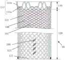
图1示出了本发明一实施例所提供的医用支架10的结构示意图。如图1所示,所述医用支架10包括支架本体100和束缚件200,所述支架本体100是由编织丝101编织而成的管网状结构。所述支架本体100的近端包括多个由所述编织丝101弯折形成且沿所述支架本体100的周向布置的近端凸起111,以及所述支架本体100的远端包括多个由所述编织丝101弯折形成且沿所述支架本体100的周向布置的远端凸起121。具体的,近端凸起111和远端凸起121指的是编织丝101分别在近端和远端弯折所形成的连续部。Fig. 1 shows a schematic structural view of a
可选地,所述近端凸起111和所述远端凸起121均呈“V”型,且所述V型结构的顶部为弧线段,以避免所述近端凸起111和所述远端凸起121对血管壁造成损伤。所述近端凸起111和所述远端凸起121的开口相对布置,也即,作为所述近端凸起111的V型的开口朝向远端布置,作为远端凸起121的V型的开口朝向近端布置。所述束缚件200束缚所述编织丝101的端头,以保持所述支架本体100的管网状结构,避免所述支架本体100散开,且避免所述编织丝出现自由端头,进而避免自由端头对血管壁的刺激,降低医用支架10植入血管壁后的远期再狭窄的发生概率。所述束缚件200设置在所述近端凸起111和所述远端凸起121之间。换句话说,本实施例中,所述编织丝101在所述医用支架10的任一端部处弯折并反向延伸后再通过所述束缚件200连接,从而所述医用支架100的任一个所述近端凸起111和任一个所述远端凸起121均为一体式的“V”型结构,而非拼接形成,这样做的好处是所述编织丝能够在所述医用支架的近端或远端具有反向作用力,具体是在近端端部弯折后具有由近端指向远端的力,以及在远端端部弯折后具有由远端指向近端的力,两个方向的力相互作用,减少医用支架10的两个端部在轴向上位移,以使得所述医用支架10的两个端部具有良好的径向支撑力和抗移位性能。Optionally, both the
需要说明的是,所述束缚件200可以为整体式结构,例如为一个连接管,所述编织丝101的两个端头均伸入所述连接管的管腔中,并与所述连接管采用任意合适的方式连接。或者,所述束缚件200可包括两个部分,例如两根连接管,两个所述连接管分别套设在一个所述端头上,然后两个所述连接管通过任意合适的方式连接。所述连接管的材料优选与所述编织丝101的材料相同。It should be noted that the binding
在一些实施例中,所述支架本体100由一根编织丝101编织而成,相应地,所述束缚件200的数量也为一个,以将一根所述编织丝101的两个端头束缚。In some embodiments, the
在另一些实施例中,所述支架本体100由两根以上的所述编织丝101编织而成,以提高所述医用支架10的贴壁性。与之相应地,所述束缚件200的数量为至少两个,且每个所述束缚件200用于束缚所述编织丝101的两个端头。这里,需要说明的是,一个所述束缚件200所束缚的两个端头可以来自于同一根所述编织丝101,也可以来自于不同的两根所述编织丝101,只要确保所述支架本体100的端头被束缚后,所述支架本体100不会散开即可。In some other embodiments, the
当所述支架本体100由两根以上的所述编织丝101编织而成时,优选任意两个所述束缚件200在所述医用支架10的轴向上的距离大于或等于零。这样的设置,使得所述医用支架10处于压握状态时,多个所述束缚件200在所述医用支架10的轴向上错开,不会重叠,从而减小压握态的所述医用支架10的直径,有利于在输送所述医用支架10时减小输送及释放阻力。When the
多个所述束缚件200在所述医用支架10可以按照任意合适的方式沿所述医用支架10的周向布置。举例来说,所有的所述束缚件200可以被分为两个束缚件组,每个所述束缚件组包括至少一个所述束缚件200,两个所述束缚件组在所述医用支架10的周向上对称布置。此外,还优选一个所述束缚件组中的所述束缚件200可以与另一个所述束缚件组中的所述束缚件200交替布置。A plurality of binding
进一步地,请继续参考图1并结合图2及图3,所述支架本体100包括第一支架段110和第二支架段120,所述第一支架段110连接于所述第二支架段120的近端,且所述第一支架段110包括所述近端凸起111。所述近端凸起111包括第一凸起111a和第二凸起111b,在所述医用支架10的轴向上,所述第二凸起111b部分地与所述第一凸起111a重合,且所述第二凸起111b的近端延伸超出所述第一凸起111a。在所述医用支架10的周向上,相邻两个所述第二凸起111b之间设置至少一个所述第一凸起111a,例如一个、两个、三个、或更多个,通常所述第一凸起111a和所述第二凸起111b的总数量为8~16个。这样一来,所述编织丝101在所述医用支架10的所述近端凸起111所在的轴向长度范围内的覆盖率较小,空隙区域较大,当所述医用支架10应用于静脉压迫综合征中的累及髂-下腔的病变的治疗时,如图3所示,可以将所述医用支架10的近端定位于左髂总静脉和右髂总静脉的分叉处,并使所述近端凸起111至少部分地伸入下腔静脉,提高所述医用支架10的近端的定位位置,避免所述医用支架10植入后髂总静脉(左髂总静脉或右髂总静脉中的一者,例如左髂总静脉)的位于所述医用支架10的近端侧的部分发生“盖帽”现象,还不会对对侧静脉的血流造成影响。所述“盖帽”现象是指髂总静脉的位于所述医用支架10的近端侧的部分的直径小于所述医用支架10扩张后的直径的现象。Further, please continue to refer to FIG. 1 in conjunction with FIG. 2 and FIG. 3 , the
可选地,在所述医用支架10的轴向上,所述第二凸起111b的延伸超出所述第一凸起111a的部分的长度H为5mm~15mm。以及,所述第二凸起111b的超出所述第一凸起111a的部分还可以向外翻折,以使得所述医用支架10的近端具有外扩的开口,其好处是,当所述医用支架10的近端凸起111伸入所述下腔静脉时,可以使得所述医用支架10的轴线与相应髂总静脉例如左髂总静脉(以所述医用支架10植入左髂总静脉为例)的轴线基本重合,有利于相应的髂总静脉内的血流沿所述医用支架10的内腔流通。可选地,所述第二凸起111b的超出所述第一凸起111a的部分的外翻角度为0°~60°,以使得所述第二凸起111b的超出所述第一凸起111a的部分与所述医用支架10的外表面所形成的夹角α的角度为120°~180°。Optionally, in the axial direction of the
进一步优选地,如图4所示,所述第一支架段110还包括过渡段112,所述过渡段112连接于所述第二支架段120的近端,所述过渡段112的远端连接所述近端凸起111,并且所述过渡段112的网孔的孔径大于所述第二支架段120的网孔的孔径。请继续参考图3,所述过渡段112也可以伸入下腔静脉,进一步提高所述医用支架10的锚定位置,并对下腔静脉中靠近髂总静脉的压迫病变进行治疗。所述过渡段112的网孔的孔径大,网孔密度小,不会对对侧静脉的血流造成影响。可选地,在所述医用支架10的轴向上所述过渡段112的网孔孔径可以为5mm~15mm,且在所述医用支架10的轴向上,所述过渡段112上的网孔的数量可以为一个或两个以上,具体根据需要设置。Further preferably, as shown in FIG. 4 , the
以及,所述第二支架段120还包括第一节段122和第二节段123,所述第一节段122连接于所述第一支架段110的远端,所述第二节段123连接于所述第一节段122的远端,且所述第二节段123的网孔的孔径小于所述第一节段122的网孔的孔径。所述第一节段122用于设置在压迫病变部位,所述第二节段123具有较好的柔顺性,并设置在压迫病变部位的远端,以顺应血管的弯曲形态。And, the
此外,所述第二支架段120的远端形成所述远端凸起121,所述远端凸起121连接于所述第二节段123的远端。所述远端凸起121可以采用类似于所述近端凸起111的方式布置,以使得所述第二支架段120可对累及远端病变的静脉分支进行扩张,不影响其他分支血流。In addition, the distal end of the
所述医用支架10可通过如下方法制造:Described
首先,提供编织模具20(如图5所示)和所述编织丝101。其中,所述编织模具20包括芯轴310、多个近端定位件320和多个远端定位件(图中未示出),多个所述近端定位件320设置在所述芯轴310的近端,并沿所述芯轴310的周向间隔布置。多个所述远端定位件设置在所述芯轴310的远端,并沿所述芯轴310的周向间隔布置。Firstly, a braiding mold 20 (as shown in FIG. 5 ) and the
接着,使所述编织丝101在所述编织模具20上交错编织以形成管网状的所述支架本体100。在编织过程中,使所述编织丝101在所述近端定位件320处弯折并反向延伸,以形成所述近端凸起111,以及使所述编织丝101在所述远端定位件处弯折并反向延伸,以形成所述远端凸起121。且使所述编织丝101的端头位于所述近端定位件320与所述远端定位件之间。其中,近端凸起111和远端凸起121指的是编织丝101分别在近端和远端弯折所形成的连续部。进一步地,所述近端凸起111和所述远端凸起121均呈“V”型。需要说明的是,图中编织丝101显示不连贯的位置例如图中S处所示,表示该编织丝101在该位置被另一编织丝101压住,实际中编织丝101是连续的。Next, the
最后,利用所述束缚件200束缚所述编织丝101的端头。所述束缚件200例如是连接管,所述连接管包覆所述编织丝101的两个端头,并通过焊接的方式使所述连接管200与两个端头连接。Finally, the ends of the braided
其中,当所述编织丝101的数量为两根以上时,所述支架本体100上具有四个以上的端头,其中每两个端头形成一个端头对,并通过一个束缚件200进行束缚,如此所述支架本体100上形成至少两个所述端头对。可以理解,同一个所述端头对中的两个对头可以来自于一根所述编织丝101,也可以来源于两根不同的所述编织丝101。在编织过程中,使所述端头对在所述芯轴310的轴向上错开预定距离。所述预定距离根据实际情况来设定,只要能够使任意两个所述束缚件200在所述医用支架10的轴向上的距离大于或等于零即可。Wherein, when the number of the braided
实际编织过程时,可以将所有的所述端头对分为两个端头对组,并使两个所述端头对组在所述芯轴310的周向上对称布置,且不同的端头对组中的端头对在所述芯轴310的轴向上交替布置。During the actual weaving process, all the end pairs can be divided into two end pairs, and the two end pairs are symmetrically arranged in the circumferential direction of the
另外,在编织时,所述编织丝101可采用一压一、一压二、二压一、或二压二的方式进行编织。In addition, during weaving, the
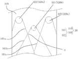
接下去以多根编织丝101在多个近端定位件320处的弯折并相互交错地编织为例对编织方式做进一步说明。为便于理解,以下将涉及的多根所述编织丝101分别被称之为第一根编织丝101a、第二根编织丝101b、第三根编织丝101c、第四跟编织丝101d等,多个近端定位件320被分别称之为第一个近端定位件320a、第二个近端定位件320b、第三个近端定位件320c、第四个近端定位件320d等。Next, the weaving method will be further described by taking the bending of the plurality of
当采用一压一的方式编织时,如图5所示,第一根编织丝101a在第一个近端定位件320处弯折,以使所述第一根编织丝101a被分为第一节段和第二节段,且所述第一节段位于第一个近端定位件320的左侧、所述第二节段位于所述第一个近端定位件的右侧。第二根编织丝101b在第二个近端定位件320b处弯折,并被分为第三节段和第四节段,且所述的第三节段位于所述第二个近端定位件320b的左侧、所述第四节段位于所述第二个近端定位件320b的右侧。第三根编织丝101c在第三个近端定位件320c处弯折,并被分为第五节段和第六节段,且所述第五节段位于所述第三个近端定位件320c的左侧、所述第六节段位于所述第三个近端定位件320c的右侧。所述第二根编织丝101b的所述第三节段压在所述第一根编织丝101a的所述第二节段上,所述第三根编织丝101c的所述第五节段压在所述第二根编织丝101b的所述第四节段上,所述第一根编织丝101b的所述第二节段压在所述第三根编织丝101c的所述第五节段上。在所述医用支架10的其他位置,编织丝101按照这种交错方式依次编织即可。一压一的编织方式可以提高所述医用支架10的径向支撑力。When knitting in a one-press-one manner, as shown in FIG. segment and a second segment, and the first segment is located on the left side of the first
请参考图6,图6中还示出了第四根编织丝101d和第四个近端定位件320d,所述第四根编织丝101d在第四个近端定位件320d处弯折,并被分为第七节段和第八节段,所述第七节段位于所述第四个近端定位件320d的左侧、所述第八节段位于所述第四定位段320d的右侧。当采用一压二的方式编织时,所述第一根编织丝101a的第二节段压在所述第二根编织丝101b的第三节段以及所述第三根编织丝101c的第五节段上,所述第三根编织丝101c的第五节段和所述第四根编织丝101d的第七节段压在所述第二根编织丝101b的第四节段上。依次类推进行编织。Please refer to FIG. 6, which also shows a
请参考图7,当采用二压一的方式编织时,所述第二根编织丝101b的所述第三节段和所述第三根编织丝101c的所述第五节段压在所述第一根编织丝101a的所述第二节段上,所述第二根编织丝101b的所述第四节段压在所述第三根编织丝101c的所述第五节段以及所述第四根编织丝101d的所述第七节段上。依次类推进行编织。一压二或者二压一的编织方式有利于提高所述医用支架10的柔顺性。Please refer to FIG. 7 , when two-press-one knitting is adopted, the third segment of the
请再参考图8,当采用二压二的方式编织时,所述第一根编织丝101a的所述第二节段压在所述第二根编织丝101b的第三节段上,所述第二根编织丝101b的所述第四节段压在所述第三根编织丝101c的所述第五节段上,所述第三根编织丝101c的所述第五节段还压在所述第一根编织丝101a的所述第二节段上,所述第四根编织丝101d的所述第七节段压在所述第三根编织丝101c的所述第六节段上。依次类推进行编织。二压二的编织方式,可以提高所述医用支架10的柔顺性,并还提高编织效率。Please refer to FIG. 8 again, when the two-press-two knitting method is adopted, the second segment of the
此外,为使所述近端凸起111包括所述第一凸起111a和所述第二凸起111b,请参考图5,所述近端定位件320包括第一近端定位件321和第二近端定位件322,在所述芯轴310的轴向上,所述第二近端定位件322位于所述第一近端定位件321的近端侧,在所述芯轴310的周向上,相邻两个所述第二近端定位件322之间设有至少一个所述第一近端定位件321。当所述编织丝101在所述第一近端定位件321处弯折时形成所述第一凸起111a,当所述编织丝101在所述第二定位件322处弯折时形成所述第二凸起111b。利用所述第一近端定位件321和所述第二近端定位件322的排布位置来使所述编织丝101形成所述第一凸起111a和所述第二凸起111b,简单方便,易于实现。In addition, to make the
虽然本发明披露如上,但并不局限于此。本领域的技术人员可以对本发明进行各种改动和变型而不脱离本发明的精神和范围。这样,倘若本发明的这些修改和变型属于本发明权利要求及其等同技术的范围之内,则本发明也意图包含这些改动和变型在内。Although the present invention is disclosed above, it is not limited thereto. Those skilled in the art can make various changes and modifications to the present invention without departing from the spirit and scope of the present invention. Thus, if these modifications and variations of the present invention fall within the scope of the claims of the present invention and their equivalent technologies, the present invention also intends to include these modifications and variations.
Claims (12)
Priority Applications (1)
| Application Number | Priority Date | Filing Date | Title |
|---|---|---|---|
| CN202111183956.6ACN115957057A (en) | 2021-10-11 | 2021-10-11 | A kind of medical bracket and its manufacturing method |
Applications Claiming Priority (1)
| Application Number | Priority Date | Filing Date | Title |
|---|---|---|---|
| CN202111183956.6ACN115957057A (en) | 2021-10-11 | 2021-10-11 | A kind of medical bracket and its manufacturing method |
Publications (1)
| Publication Number | Publication Date |
|---|---|
| CN115957057Atrue CN115957057A (en) | 2023-04-14 |
Family
ID=87351764
Family Applications (1)
| Application Number | Title | Priority Date | Filing Date |
|---|---|---|---|
| CN202111183956.6APendingCN115957057A (en) | 2021-10-11 | 2021-10-11 | A kind of medical bracket and its manufacturing method |
Country Status (1)
| Country | Link |
|---|---|
| CN (1) | CN115957057A (en) |
Citations (5)
| Publication number | Priority date | Publication date | Assignee | Title |
|---|---|---|---|---|
| US20130245745A1 (en)* | 2012-03-16 | 2013-09-19 | Microvention, Inc. | Stent and stent delivery device |
| CN204766039U (en)* | 2015-05-04 | 2015-11-18 | 苏州茵络医疗器械有限公司 | Development support |
| US20160199204A1 (en)* | 2015-01-12 | 2016-07-14 | Microvention, Inc. | Stent |
| CN112754584A (en)* | 2021-01-06 | 2021-05-07 | 微创神通医疗科技(上海)有限公司 | Vascular implant and medical equipment |
| CN218484711U (en)* | 2021-10-11 | 2023-02-17 | 上海蓝脉医疗科技有限公司 | Medical support |
- 2021
- 2021-10-11CNCN202111183956.6Apatent/CN115957057A/enactivePending
Patent Citations (5)
| Publication number | Priority date | Publication date | Assignee | Title |
|---|---|---|---|---|
| US20130245745A1 (en)* | 2012-03-16 | 2013-09-19 | Microvention, Inc. | Stent and stent delivery device |
| US20160199204A1 (en)* | 2015-01-12 | 2016-07-14 | Microvention, Inc. | Stent |
| CN204766039U (en)* | 2015-05-04 | 2015-11-18 | 苏州茵络医疗器械有限公司 | Development support |
| CN112754584A (en)* | 2021-01-06 | 2021-05-07 | 微创神通医疗科技(上海)有限公司 | Vascular implant and medical equipment |
| CN218484711U (en)* | 2021-10-11 | 2023-02-17 | 上海蓝脉医疗科技有限公司 | Medical support |
Similar Documents
| Publication | Publication Date | Title |
|---|---|---|
| CN110731843A (en) | a vascular stent | |
| CN105769383B (en) | Aorta bare stent and aorta interlayer stent | |
| CN106132356B (en) | Vascular and intracorporeal catheter therapy devices and methods | |
| CN104720936A (en) | Use of safe valve stents and valve replacement devices incorporating them | |
| CN103784222B (en) | A kind of self-expandable stent | |
| CN106859729A (en) | One kind takes bolt mounting system | |
| CN204581599U (en) | The valve bracket of use safety and there is the valve replacement device of this valve bracket | |
| CN109481109B (en) | Braided stent | |
| CN103124524A (en) | Braided medical device and manufacturing method thereof | |
| CN218484711U (en) | Medical support | |
| CN113925653B (en) | Stent delivery devices and systems | |
| CN108078657A (en) | Braided support delivery components | |
| CN107714244A (en) | Vein blood vessel is from swollen support | |
| CN114652486A (en) | Covered stent | |
| CN108371572B (en) | Spiral self-expansion bracket | |
| CN205612592U (en) | Naked support of aorta and aorta intermediate layer support | |
| CN104736107B (en) | The support of variable cross-section | |
| CN115957057A (en) | A kind of medical bracket and its manufacturing method | |
| CN217548324U (en) | Medical support | |
| CN110613540A (en) | Blood vessel implantation stent | |
| CN112137673A (en) | Spring coil and its anti-untwisting parts | |
| CN212308144U (en) | Bevel bracket | |
| CN211560527U (en) | Tectorial membrane support for central vein | |
| CN212016424U (en) | Medical balloon, balloon catheter and medical device | |
| CN110613539A (en) | Blood vessel support capable of positioning |
Legal Events
| Date | Code | Title | Description |
|---|---|---|---|
| PB01 | Publication | ||
| PB01 | Publication | ||
| SE01 | Entry into force of request for substantive examination | ||
| SE01 | Entry into force of request for substantive examination |