CN115947285A - A method and device for press-fitting beautifying agent - Google Patents
A method and device for press-fitting beautifying agentDownload PDFInfo
- Publication number
- CN115947285A CN115947285ACN202310049954.0ACN202310049954ACN115947285ACN 115947285 ACN115947285 ACN 115947285ACN 202310049954 ACN202310049954 ACN 202310049954ACN 115947285 ACN115947285 ACN 115947285A
- Authority
- CN
- China
- Prior art keywords
- press
- agent
- mixing tank
- beautifying agent
- pushing disc
- Prior art date
- Legal status (The legal status is an assumption and is not a legal conclusion. Google has not performed a legal analysis and makes no representation as to the accuracy of the status listed.)
- Granted
Links
Images


Classifications
- B—PERFORMING OPERATIONS; TRANSPORTING
- B01—PHYSICAL OR CHEMICAL PROCESSES OR APPARATUS IN GENERAL
- B01F—MIXING, e.g. DISSOLVING, EMULSIFYING OR DISPERSING
- B01F27/00—Mixers with rotary stirring devices in fixed receptacles; Kneaders
- B01F27/80—Mixers with rotary stirring devices in fixed receptacles; Kneaders with stirrers rotating about a substantially vertical axis
- B01F27/805—Mixers with rotary stirring devices in fixed receptacles; Kneaders with stirrers rotating about a substantially vertical axis wherein the stirrers or the receptacles are moved in order to bring them into operative position; Means for fixing the receptacle
- B01F27/806—Mixers with rotary stirring devices in fixed receptacles; Kneaders with stirrers rotating about a substantially vertical axis wherein the stirrers or the receptacles are moved in order to bring them into operative position; Means for fixing the receptacle with vertical displacement of the stirrer, e.g. in combination with means for pivoting the stirrer about a vertical axis in order to co-operate with different receptacles
- B—PERFORMING OPERATIONS; TRANSPORTING
- B01—PHYSICAL OR CHEMICAL PROCESSES OR APPARATUS IN GENERAL
- B01F—MIXING, e.g. DISSOLVING, EMULSIFYING OR DISPERSING
- B01F33/00—Other mixers; Mixing plants; Combinations of mixers
- B01F33/70—Mixers specially adapted for working at sub- or super-atmospheric pressure, e.g. combined with de-foaming
- B—PERFORMING OPERATIONS; TRANSPORTING
- B01—PHYSICAL OR CHEMICAL PROCESSES OR APPARATUS IN GENERAL
- B01F—MIXING, e.g. DISSOLVING, EMULSIFYING OR DISPERSING
- B01F35/00—Accessories for mixers; Auxiliary operations or auxiliary devices; Parts or details of general application
- B01F35/10—Maintenance of mixers
- B01F35/12—Maintenance of mixers using mechanical means
- B—PERFORMING OPERATIONS; TRANSPORTING
- B01—PHYSICAL OR CHEMICAL PROCESSES OR APPARATUS IN GENERAL
- B01F—MIXING, e.g. DISSOLVING, EMULSIFYING OR DISPERSING
- B01F35/00—Accessories for mixers; Auxiliary operations or auxiliary devices; Parts or details of general application
- B01F35/181—Preventing generation of dust or dirt; Sieves; Filters
- B01F35/189—Venting, degassing or ventilating of gases, fumes or toxic vapours during mixing
- B—PERFORMING OPERATIONS; TRANSPORTING
- B01—PHYSICAL OR CHEMICAL PROCESSES OR APPARATUS IN GENERAL
- B01F—MIXING, e.g. DISSOLVING, EMULSIFYING OR DISPERSING
- B01F35/00—Accessories for mixers; Auxiliary operations or auxiliary devices; Parts or details of general application
- B01F35/45—Closures or doors specially adapted for mixing receptacles; Operating mechanisms therefor
- B01F35/453—Closures or doors specially adapted for mixing receptacles; Operating mechanisms therefor by moving them perpendicular to the plane of the opening
- B—PERFORMING OPERATIONS; TRANSPORTING
- B65—CONVEYING; PACKING; STORING; HANDLING THIN OR FILAMENTARY MATERIAL
- B65B—MACHINES, APPARATUS OR DEVICES FOR, OR METHODS OF, PACKAGING ARTICLES OR MATERIALS; UNPACKING
- B65B3/00—Packaging plastic material, semiliquids, liquids or mixed solids and liquids, in individual containers or receptacles, e.g. bags, sacks, boxes, cartons, cans, or jars
- B65B3/22—Defoaming liquids in connection with filling
- B—PERFORMING OPERATIONS; TRANSPORTING
- B65—CONVEYING; PACKING; STORING; HANDLING THIN OR FILAMENTARY MATERIAL
- B65B—MACHINES, APPARATUS OR DEVICES FOR, OR METHODS OF, PACKAGING ARTICLES OR MATERIALS; UNPACKING
- B65B3/00—Packaging plastic material, semiliquids, liquids or mixed solids and liquids, in individual containers or receptacles, e.g. bags, sacks, boxes, cartons, cans, or jars
- B65B3/26—Methods or devices for controlling the quantity of the material fed or filled
- B65B3/30—Methods or devices for controlling the quantity of the material fed or filled by volumetric measurement
- B—PERFORMING OPERATIONS; TRANSPORTING
- B01—PHYSICAL OR CHEMICAL PROCESSES OR APPARATUS IN GENERAL
- B01F—MIXING, e.g. DISSOLVING, EMULSIFYING OR DISPERSING
- B01F2101/00—Mixing characterised by the nature of the mixed materials or by the application field
- B01F2101/30—Mixing paints or paint ingredients, e.g. pigments, dyes, colours, lacquers or enamel
- Y—GENERAL TAGGING OF NEW TECHNOLOGICAL DEVELOPMENTS; GENERAL TAGGING OF CROSS-SECTIONAL TECHNOLOGIES SPANNING OVER SEVERAL SECTIONS OF THE IPC; TECHNICAL SUBJECTS COVERED BY FORMER USPC CROSS-REFERENCE ART COLLECTIONS [XRACs] AND DIGESTS
- Y02—TECHNOLOGIES OR APPLICATIONS FOR MITIGATION OR ADAPTATION AGAINST CLIMATE CHANGE
- Y02W—CLIMATE CHANGE MITIGATION TECHNOLOGIES RELATED TO WASTEWATER TREATMENT OR WASTE MANAGEMENT
- Y02W30/00—Technologies for solid waste management
- Y02W30/50—Reuse, recycling or recovery technologies
- Y02W30/91—Use of waste materials as fillers for mortars or concrete
Landscapes
- Chemical & Material Sciences (AREA)
- Chemical Kinetics & Catalysis (AREA)
- Engineering & Computer Science (AREA)
- Mechanical Engineering (AREA)
- Health & Medical Sciences (AREA)
- General Health & Medical Sciences (AREA)
- Toxicology (AREA)
- Coating Apparatus (AREA)
- Mixers With Rotating Receptacles And Mixers With Vibration Mechanisms (AREA)
- Mixers Of The Rotary Stirring Type (AREA)
- Filling Of Jars Or Cans And Processes For Cleaning And Sealing Jars (AREA)
- Treatment Of Fiber Materials (AREA)
Abstract
Translated fromChinese
Description
Translated fromChinese技术领域technical field
本发明属于美缝剂生产设备技术领域,尤其涉及一种美缝剂压装方法。The invention belongs to the technical field of beautifying agent production equipment, and in particular relates to a method for pressing and installing beautifying agent.
背景技术Background technique
在房屋装饰施工中,会采用瓷砖、大理石等来铺贴地面和墙面。在瓷砖或大理石铺贴后,相邻瓷砖或者相邻大理石之间会有缝隙,美缝剂则是用来填充这些缝隙的装饰材料。In the house decoration construction, tiles, marble, etc. are used to pave the ground and walls. After the tiles or marbles are laid, there will be gaps between adjacent tiles or adjacent marbles, and the beautifying agent is a decorative material used to fill these gaps.
美缝剂是一种流体状或者膏体状的建筑材料,由专门的工厂生产。在装修中,要使得用于填缝的美缝剂具有与瓷砖或大理石相匹配的颜色,需要将工厂生产的基本颜色的美缝剂按照设定的比例进行调色。调色的方式是先要将几种设定好质量比例的基本颜色的美缝剂倒入搅拌罐用真空搅拌装置进行搅拌,搅拌充分均匀后,还需要用分装灌注装置将搅拌罐中的已调色好的美缝剂灌装到美缝剂分装筒内。Beauty joint agent is a fluid or paste-like building material, which is produced by a special factory. In decoration, in order to make the beautifying agent used for caulking match the color of tiles or marble, it is necessary to mix the basic color beautifying agent produced by the factory according to the set ratio. The way of toning is to first pour several kinds of beautifying agents of basic colors with a set mass ratio into the mixing tank and stir them with a vacuum stirring device. The toned beautifying agent is filled into the beautifying agent dispensing cylinder.
在分装灌注装置中,是通过推挤圆盘在下压机构驱动下将搅拌罐内的流体状或膏体状的美缝剂经搅拌罐底部的灌装通道挤压推出,灌装到美缝剂分装筒。为提高推挤圆盘在灌装时的推挤可靠性,避免物料沿推挤圆盘与搅拌罐内壁之间的缝隙溢出,现有技术中,在推挤圆盘的周面上开设凹槽,凹槽内设置有胶圈。但这种结构,在美缝剂实际压装过程中,在推挤圆盘进入搅拌罐内部后,由于胶圈使得推挤圆盘与搅拌罐内壁之间形成密封,这导致搅拌罐内位于美缝剂上方空间内空气无法排出,随着推挤圆盘的下降,这部分在搅拌罐内无法排出的空气的压力会越来越大,强行驱动推挤圆盘,会造成搅拌罐、推挤圆盘甚至是下压机构的。于是,有人想到在推挤圆盘上开设排气孔,在推挤圆盘在压到美缝剂之前让空气从排气孔排出,这样虽可以排除掉搅拌罐内位于美缝剂上方的空气,但是排气孔的开设又使得推挤圆盘在推挤美缝剂过程中,有少量美缝剂从排气孔溢出,不仅降低了推挤可靠性,而且美缝剂也会粘在推挤圆盘及排气孔中,污染了推挤圆盘,使得推挤圆盘每进行一次压装工作都要进行清洗,增加了工人的工作量。In the sub-packaging and filling device, the fluid or paste-like beautifying agent in the mixing tank is squeezed out through the filling channel at the bottom of the mixing tank under the drive of the pressing mechanism through the pushing disc, and filled to the beautifying joint. Dosage dispenser. In order to improve the pushing reliability of the pushing disc during filling and prevent the material from overflowing along the gap between the pushing disc and the inner wall of the mixing tank, in the prior art, grooves are provided on the peripheral surface of the pushing disc , an apron is arranged in the groove. However, with this structure, in the actual press-fitting process of the beauty joint agent, after the pushing disc enters the inside of the mixing tank, the rubber ring makes a seal between the pushing disc and the inner wall of the mixing tank, which causes the inside of the mixing tank to be located in the beautiful The air in the space above the caulking agent cannot be discharged. As the pushing disc descends, the pressure of this part of the air that cannot be discharged in the mixing tank will increase. Forcibly driving the pushing disc will cause the mixing tank, pushing The disc is even a push-down mechanism. Therefore, someone thought of opening a vent hole on the pushing disc, and let the air be exhausted from the vent hole before the pushing disc is pressed against the beautifying agent, so that the air above the beautifying agent in the mixing tank can be eliminated , but the opening of the vent hole makes the pushing disc in the process of pushing the beautifying agent, a small amount of beautifying agent overflows from the vent hole, which not only reduces the reliability of pushing, but also the beautifying agent will stick to the pushing disc. Squeeze the disk and the exhaust hole, pollute the push disk, so that the push disk will be cleaned every time it is pressed and installed, which increases the workload of the workman.
发明内容Contents of the invention
本发明所要解决的技术问题是提供一种推挤可靠、推挤过程既能将搅拌罐内空气排出,又能保持推挤圆盘清洁的美缝剂压装方法,以克服现有技术存在的缺陷。The technical problem to be solved by the present invention is to provide a beautifying agent pressing method that is reliable in pushing, can not only discharge the air in the mixing tank during the pushing process, but also keep the pushing disc clean, so as to overcome the problems existing in the prior art. defect.
为解决上述技术问题,本发明采用如下的技术方案:In order to solve the problems of the technologies described above, the present invention adopts the following technical solutions:
一种美缝剂压装方法,用分装灌注装置将搅拌罐中的美缝剂推挤经所述搅拌罐底部的灌装通道灌注到美缝剂分装筒中,所述分装灌注装置包括推挤圆盘以及驱动所述推挤圆盘下压的下压机构,所述推挤圆盘的直径略小于所述搅拌罐内壁直径,所述分装灌注装置还包括有覆盖薄膜和挤压胶条,所述美缝剂压装方法的步骤为:A method for press-packing a beautifying agent, using a filling device to push the beautifying agent in a mixing tank through a filling channel at the bottom of the agitating tank and pouring it into a beautifying agent filling cylinder, and the dispensing and filling device includes Pushing the disc and a press-down mechanism that drives the pushing disc to press down, the diameter of the pushing disc is slightly smaller than the diameter of the inner wall of the stirring tank, and the sub-packing and filling device also includes a covering film and a pressing Adhesive strips, the steps of the beauty seam agent pressing method are:
S101、将盛装有美缝剂的搅拌罐放置到推挤圆盘的正下方,将覆盖薄膜覆盖在搅拌内美缝剂的表面,并在覆盖薄膜的上表面沿搅拌罐内壁放置一圈挤压胶条,将美缝剂分装筒套在灌装通道上;S101. Place the mixing tank containing the beautifying agent directly under the pushing disc, cover the surface of the beautifying agent in the stirring with the covering film, and place a circle of extrusion on the upper surface of the covering film along the inner wall of the stirring tank Adhesive strips, cover the beautifying agent dispensing tube on the filling channel;
S102、下压机构驱动推挤圆盘下降进入搅拌罐内,在推挤圆盘压到美缝剂之前,使搅拌罐内的空气从推挤圆盘和搅拌罐内壁之间的间隙排出,在压到美缝剂时,使推挤圆盘的边缘压在所述挤压胶条上,之后下压机构持续驱动推挤圆盘在搅拌罐内推挤美缝剂,使得美缝剂经灌装通道灌注到美缝剂分装筒中。S102. The push-down mechanism drives the pushing disc down into the mixing tank. Before the pushing disc is pressed against the beautifying agent, the air in the mixing tank is discharged from the gap between the pushing disc and the inner wall of the mixing tank. When the beautifying agent is pressed, the edge of the pushing disc is pressed against the extruded rubber strip, and then the pressing mechanism continues to drive the pushing disc to push the beautifying agent in the mixing tank, so that the beautifying agent is poured The filling channel is poured into the beautifying agent dispensing cylinder.
采用上述技术方案,由于推挤圆盘直径略比搅拌罐内壁直径小,这样推挤圆盘与搅拌罐的内壁之间具有缝隙,在推挤圆盘下压过程中,在压到美缝剂上表面之前,搅拌罐内的空气能够从缝隙排出。当接触到美缝剂上表面时,推挤圆盘和美缝剂之间不会有空气存在。另外,推挤圆盘边缘压在加压胶条上能够将搅拌罐内壁上的美缝剂刮干净,而覆盖薄膜的使用可以避免推挤圆盘上沾上美缝剂,避免被美缝剂污染。With the above technical solution, since the diameter of the pushing disc is slightly smaller than the diameter of the inner wall of the mixing tank, there is a gap between the pushing disc and the inner wall of the mixing tank. The air in the mixing tank can be expelled through the gap before the upper surface. When in contact with the top surface of the grout, there will be no air between the push disc and the grout. In addition, pressing the edge of the pushing disc on the pressurized rubber strip can scrape off the beautifying agent on the inner wall of the mixing tank, and the use of the covering film can prevent the beautifying agent from being stained on the pushing disc and being covered by the beautifying agent. pollute.
因此,本发明的美缝剂压装方法具有推挤可靠、推挤过程既能将搅拌罐内空气排出,又能保持推挤圆盘清洁的优点。Therefore, the press-packing method of the beautifying agent of the present invention has the advantages of reliable pushing, the pushing process can not only discharge the air in the mixing tank, but also keep the pushing disc clean.
附图说明Description of drawings
图1为本美缝剂调色机的结构示意图;Figure 1 is a schematic diagram of the structure of the beauty sewing agent toning machine;
图2为分装罐装装置的结构示意图;Fig. 2 is the structural representation of packing device;
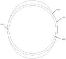
图3为支撑座的俯视图;Figure 3 is a top view of the support seat;
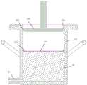
图4为推挤圆板在搅拌罐内还未推挤美缝剂时的剖视图;Fig. 4 is a cross-sectional view of the push circular plate when the beautifying agent has not been pushed in the mixing tank;
图5为推挤圆板在搅拌罐内推挤美缝剂时的剖视图。Fig. 5 is a cross-sectional view of the pushing circular plate pushing the beauty joint agent in the mixing tank.
具体实施方式Detailed ways
本发明的美缝剂压装方法在如图1所示的美缝剂调色机中应用,为能够清楚地说明本发明的美缝剂压装方法,本具体实施方式对对美缝剂调色机的结构作详细介绍。The beauty seam agent pressing method of the present invention is applied in the beauty seam agent coloring machine as shown in Figure 1. In order to clearly illustrate the beauty seam agent pressing method of the present invention, this specific embodiment is about the beauty seam agent adjustment. The structure of the color machine is introduced in detail.
该美缝剂调色机包括机架100、设于机架100上的真空搅拌装置200和分装灌注装置300。The beautifying agent toning machine includes a
其中,机架100包括台面101、位于台面101下方的柜体102、设于台面101上的两根滑轨103、设于台面101上的第一支架1051和第二支架1052。滑轨103从第一支架1051的下方位置延伸至第二支架1052的下方位置。滑轨103上还设有能够沿滑轨103移动的支撑座104。The
真空搅拌装置200包括搅拌罐210、搅拌机220、真空泵230以及升降机构240。升降机构240安装在第一支架1051上,搅拌机220则安装在升降机构240上,在升降机构240驱动下能够上升、下降。该升降机构240可以是电动升降机构或气缸升降机构或者液压升降机构。在本实施例中,该升降机构240优选电机驱动的丝杆螺母升降机构。真空泵230放置在柜体102内。The
搅拌机220包括密封盖221、设于密封盖221上方的搅拌电机222、以及设于密封盖221下方的搅拌头223。The
其中,搅拌罐210为不锈钢材质的罐体,具有耐真空强度的厚度。搅拌罐210顶部敞口,底部具有与罐体内部连通的灌装通道211。灌装通道211上具有灌装控制阀212。该灌装控制阀212可以是手动阀、电磁阀或者气动阀。为方便工人操作,也可以是脚踏式电磁阀或者脚踏式气动阀。另外,搅拌罐210两侧外壁上还设置有把手213。该把手213方便了搅拌罐210的搬运和移动。Wherein, the stirring
密封盖221上具有气体通道2211,该气体通道2211通过气体管道2212连接真空泵230。气体管道2212上设置有真空控制阀2213和压力表2214。其中,真空控制阀2213用于控制真空泵230与气体通道的连通,可以是手动阀、电磁阀或者气动阀。密封盖221的下表面设置有密封圈,密封盖220盖上搅拌罐210顶部敞口能够对搅拌罐210进行密封。The
在需要搅拌时,将调配好质量比例的各种基本色的美缝剂倒入搅拌罐210中,然后将搅拌罐210放置在支撑座104上并移动至密封盖221的正下方。密封盖221在升降机构240驱动下能够将搅拌罐221压紧固定在台面101上并封堵搅拌罐221的顶部敞口。再然后启动搅拌电机222和真空泵230,这样一边对搅拌罐210内部抽真空、一边对搅拌罐210内部的各种基本色的美缝剂进行搅拌混合,当混合充分形成新的颜色并且没有气泡冒出时停止搅拌和抽真空。压力表2214则是用于在抽真空时,观察搅拌罐210内的真空度。在本实施例中,气体管道2211还接连排气管2216,排气管2216上设置有排气阀2217。该排气管2216和排气阀2217的作用是在当需要密封盖221与搅拌罐210分离时,通过打开排气阀2216可以破环搅拌罐210内部的真空环境,使得密封盖221在升降机构驱动下能够容易与搅拌罐210分离。当然,在其它实施例中,也可以在密封盖上直接开设排气孔,将排气阀2217直接设置在排气孔上。排气阀2217可以是手动阀、电磁阀或者气动阀。When stirring is required, pour the beauty joints of various basic colors prepared in mass proportions into the
另外,密封盖220上还设有两个目镜2215,其中一个目镜2215用于打灯照明,另一个目镜用于肉眼观察。通过目镜2215进行观察,可以了解搅拌罐210中美缝剂的混合情况以及气泡排出情况。当然,在其它实施例中,其中的一个目镜上可以直接固定一个照明灯,这样就不需要手持照明灯。In addition, two
如图3所示,支撑座104由底盘1041以及设于底盘1041边缘的环形挡边1042构成,环形挡边1042朝向第二支架1052的位置具有缺口1043。当搅拌罐210放置在支撑座104上时,其罐装管道211恰好能够从缺口1043伸出。支撑座104的作用在于设置在滑轨103上承载搅拌罐210,使得搅拌罐210在支撑座104上能够沿滑轨103在搅拌机220和分装灌注装置300之间来回滑动。在其它实施例,支撑座104可以通过电机、气缸或者液压缸驱动在滑轨103上行走。As shown in FIG. 3 , the supporting
如图2所示,分装灌注装置300设置在滑轨103的上方,包括下压机构310和推挤圆盘320。As shown in FIG. 2 , the dispensing and filling
其中,下压机构310可以是液压下压机构、气动下压机构或者电动下压机构。在本实施例中,该下压机构310为竖直地固定在第二支架1052上的液压油缸311以及与液压油缸311通过液压管路连接的液压站312。液压站312放置在柜体102内。液压油缸311具有朝下延伸的活塞杆,推挤圆盘320则是固定在液压油缸311的活塞杆的下端。Wherein, the
结合图4和图5所示,分装灌注装置300还包括覆盖薄膜321和挤压胶条322。挤压胶条322优选截面为圆形的胶条。推挤圆盘320的下表面四周边缘具有环状的台阶缺口323。推挤圆盘320的直径要略比搅拌罐210内壁直径小。As shown in FIG. 4 and FIG. 5 , the dispensing and filling
再如图1和图2所示,在滑轨103内设置有分别使得支撑座104能够被止挡定位在密封盖221正下方和推挤圆盘320正下方的第一止挡块1031和第二止挡块1032。As shown in FIGS. 1 and 2 , the
本发明的美缝剂的压装方法为:The pressing method of the beauty seam agent of the present invention is:
在需要分装时,通过拉动把手213将内部装有调色搅拌好的美缝剂10的搅拌罐210,沿着滑轨103拉到推挤圆盘302的正下方。将覆盖薄膜321覆盖在搅拌罐210内的美缝剂10上表面,并在覆盖薄膜321上沿着搅拌罐210的内壁放置一圈挤压胶条322,然后将美缝剂分装筒套在灌装通道211的出口上。When dispensing is required, pull the
打开灌装控制阀212,启动上压机构310,驱动推挤圆盘320进入搅拌罐210内部。由于推挤圆盘320直径略比搅拌罐210内壁直径小,这样推挤圆盘310与搅拌罐210的内壁之间具有缝隙324,在推挤圆盘320下压过程中,在压到美缝剂10上表面之前,搅拌罐210内的空气能够从缝隙324排出。当接触到美缝剂10上表面时,推挤圆盘310和美缝剂10之间不会有空气存在。其中,台阶缺口323的存在,一方面使得推挤圆盘320的下表面能够接触到覆盖在美缝剂10上表面的覆盖薄膜321,完全压在美缝剂上,另一方面,该缺口323还可以卡住挤压胶条322,使得挤压胶条322能够紧贴住搅拌罐210的内壁,在下压的过程中将搅拌罐210内壁上的美缝剂10刮干净。而覆盖薄膜321的使用可以避免推挤圆盘320上沾上美缝剂,避免被美缝剂污染。Open the filling
随着推挤圆盘320的下压,搅拌罐210的美缝剂310会从灌装通道211流出,灌注到美缝剂分装筒内。当一支美缝剂分装筒灌满后,关闭掉灌装控制阀212,这时液压油缸311内的传感器会感测到阻力升高并反馈给液压站,液压站会控制液压油缸维持压力与阻力的平衡,不驱动推挤圆盘310下压。As the pushing
后面,继续将一根新的空的美缝剂分装筒套在灌装通道211的出口上,然后再次打开灌装控制阀212,这时液压油缸311内的传感器会感测阻力减小并反馈给液压站,液压站则会继续控制液压油缸311对推挤圆盘320施加压力,使得推挤圆盘320将美缝剂再次挤出,灌注到新的空的美缝剂分装筒内。Later, continue to put a new empty beautifying agent filling tube on the outlet of the filling
如此循环,直至将搅拌桶内的美缝剂全部挤出分装到各个美缝剂分装筒内。This cycle continues until all the beautifying agent in the mixing tank is squeezed out and distributed into each beautifying agent dispensing cylinder.
如图2所示,另外,在台面上位于推挤圆盘320的正下方还设置有增强垫块1033。该增强垫块1033的作用是在分装时,将支撑座104移动到增强垫块1033上方,通过增强垫块1033支撑住支撑座104的下表面,避免在推挤搅拌罐210内的美缝剂10时,搅拌罐210和支撑座104受力变形并保护导轨104和支撑座104的滑脚不受损伤。As shown in FIG. 2 , in addition, a reinforcing
在本发明中,搅拌罐和分装灌注装置组成了美缝剂压装装置。In the present invention, the stirring tank and the subpackaging and pouring device constitute the sealing agent pressing device.
Claims (10)
Translated fromChineseApplications Claiming Priority (2)
| Application Number | Priority Date | Filing Date | Title |
|---|---|---|---|
| CN202310033137 | 2023-01-10 | ||
| CN2023100331376 | 2023-01-10 |
Publications (2)
| Publication Number | Publication Date |
|---|---|
| CN115947285Atrue CN115947285A (en) | 2023-04-11 |
| CN115947285B CN115947285B (en) | 2025-06-13 |
Family
ID=85892287
Family Applications (7)
| Application Number | Title | Priority Date | Filing Date |
|---|---|---|---|
| CN202310060961.0APendingCN116139726A (en) | 2023-01-10 | 2023-01-19 | A kind of beautifying agent coloring machine |
| CN202320113621.5UActiveCN219376928U (en) | 2023-01-10 | 2023-01-19 | Joint beautifying agent stirring equipment |
| CN202320113859.8UActiveCN219193465U (en) | 2023-01-10 | 2023-01-19 | Track transfer platform |
| CN202320113632.3UActiveCN219376929U (en) | 2023-01-10 | 2023-01-19 | Size tank switchable seam beautifying agent stirring tank assembly |
| CN202310049954.0AActiveCN115947285B (en) | 2023-01-10 | 2023-02-01 | A method and device for pressing seam beautifying agent |
| CN202320096958.XUActiveCN219186731U (en) | 2023-01-10 | 2023-02-01 | Seam beautifying agent press fitting equipment |
| CN202320212401.8UActiveCN219376930U (en) | 2023-01-10 | 2023-02-15 | Integrated machine for stirring and split charging of seam beautifying agent |
Family Applications Before (4)
| Application Number | Title | Priority Date | Filing Date |
|---|---|---|---|
| CN202310060961.0APendingCN116139726A (en) | 2023-01-10 | 2023-01-19 | A kind of beautifying agent coloring machine |
| CN202320113621.5UActiveCN219376928U (en) | 2023-01-10 | 2023-01-19 | Joint beautifying agent stirring equipment |
| CN202320113859.8UActiveCN219193465U (en) | 2023-01-10 | 2023-01-19 | Track transfer platform |
| CN202320113632.3UActiveCN219376929U (en) | 2023-01-10 | 2023-01-19 | Size tank switchable seam beautifying agent stirring tank assembly |
Family Applications After (2)
| Application Number | Title | Priority Date | Filing Date |
|---|---|---|---|
| CN202320096958.XUActiveCN219186731U (en) | 2023-01-10 | 2023-02-01 | Seam beautifying agent press fitting equipment |
| CN202320212401.8UActiveCN219376930U (en) | 2023-01-10 | 2023-02-15 | Integrated machine for stirring and split charging of seam beautifying agent |
Country Status (1)
| Country | Link |
|---|---|
| CN (7) | CN116139726A (en) |
Families Citing this family (2)
| Publication number | Priority date | Publication date | Assignee | Title |
|---|---|---|---|---|
| CN116139726A (en)* | 2023-01-10 | 2023-05-23 | 上海靓钻建筑装饰有限公司 | A kind of beautifying agent coloring machine |
| CN117181082A (en)* | 2023-09-08 | 2023-12-08 | 安徽省特蒙德新材料有限公司 | Sewing agent customization machine |
Citations (9)
| Publication number | Priority date | Publication date | Assignee | Title |
|---|---|---|---|---|
| JPH07232117A (en)* | 1994-02-25 | 1995-09-05 | Inaba Denki Sangyo Co Ltd | Hydraulic material filler |
| CN1138001A (en)* | 1995-06-06 | 1996-12-18 | 曾冠豪 | Prepackaged liquid bone cement |
| DE29622392U1 (en)* | 1996-12-24 | 1997-02-27 | Krones Ag Hermann Kronseder Maschinenfabrik, 93073 Neutraubling | Device for filling liquids into bottles or the like. |
| JP2011214223A (en)* | 2010-03-31 | 2011-10-27 | Sumitomo Osaka Cement Co Ltd | Construction method for filling core hole of concrete structure with filler |
| CN111728867A (en)* | 2020-08-01 | 2020-10-02 | 河南方舟医疗器械有限公司 | Serum sterile preparation subpackaging output system and method |
| CN215098376U (en)* | 2020-11-30 | 2021-12-10 | 珠海尚百味食品科技有限公司 | Automatic powder split charging equipment |
| CN215098398U (en)* | 2020-11-30 | 2021-12-10 | 珠海佳霖食品有限公司 | Quantitative powder split charging device |
| CN217921447U (en)* | 2022-07-25 | 2022-11-29 | 威海速邦网络科技有限公司 | Seam beautifying agent vacuum stirring and canning all-in-one machine |
| CN219186731U (en)* | 2023-01-10 | 2023-06-16 | 上海靓钻建筑装饰有限公司 | Seam beautifying agent press fitting equipment |
Family Cites Families (5)
| Publication number | Priority date | Publication date | Assignee | Title |
|---|---|---|---|---|
| JP3067615U (en)* | 1999-09-22 | 2000-04-07 | 金▲ちー▼企業有限公司 | Stirrer structure |
| CN2635316Y (en)* | 2003-05-26 | 2004-08-25 | 广州欧仕特建材科技有限公司 | Artificial stone special vacuum stirrer |
| CN2838769Y (en)* | 2005-10-26 | 2006-11-22 | 秦皇岛首钢长白结晶器有限责任公司 | Electromagnetic stirring coil immersing varnish apparatus |
| CN204301432U (en)* | 2014-12-16 | 2015-04-29 | 四川省有色冶金研究院有限公司 | The even drying equipment of a kind of mixed-powder |
| CN207357003U (en)* | 2017-10-25 | 2018-05-15 | 安田信邦(厦门)电子科技有限公司 | A kind of combined type adhesive producing equipment |
- 2023
- 2023-01-19CNCN202310060961.0Apatent/CN116139726A/enactivePending
- 2023-01-19CNCN202320113621.5Upatent/CN219376928U/enactiveActive
- 2023-01-19CNCN202320113859.8Upatent/CN219193465U/enactiveActive
- 2023-01-19CNCN202320113632.3Upatent/CN219376929U/enactiveActive
- 2023-02-01CNCN202310049954.0Apatent/CN115947285B/enactiveActive
- 2023-02-01CNCN202320096958.XUpatent/CN219186731U/enactiveActive
- 2023-02-15CNCN202320212401.8Upatent/CN219376930U/enactiveActive
Patent Citations (9)
| Publication number | Priority date | Publication date | Assignee | Title |
|---|---|---|---|---|
| JPH07232117A (en)* | 1994-02-25 | 1995-09-05 | Inaba Denki Sangyo Co Ltd | Hydraulic material filler |
| CN1138001A (en)* | 1995-06-06 | 1996-12-18 | 曾冠豪 | Prepackaged liquid bone cement |
| DE29622392U1 (en)* | 1996-12-24 | 1997-02-27 | Krones Ag Hermann Kronseder Maschinenfabrik, 93073 Neutraubling | Device for filling liquids into bottles or the like. |
| JP2011214223A (en)* | 2010-03-31 | 2011-10-27 | Sumitomo Osaka Cement Co Ltd | Construction method for filling core hole of concrete structure with filler |
| CN111728867A (en)* | 2020-08-01 | 2020-10-02 | 河南方舟医疗器械有限公司 | Serum sterile preparation subpackaging output system and method |
| CN215098376U (en)* | 2020-11-30 | 2021-12-10 | 珠海尚百味食品科技有限公司 | Automatic powder split charging equipment |
| CN215098398U (en)* | 2020-11-30 | 2021-12-10 | 珠海佳霖食品有限公司 | Quantitative powder split charging device |
| CN217921447U (en)* | 2022-07-25 | 2022-11-29 | 威海速邦网络科技有限公司 | Seam beautifying agent vacuum stirring and canning all-in-one machine |
| CN219186731U (en)* | 2023-01-10 | 2023-06-16 | 上海靓钻建筑装饰有限公司 | Seam beautifying agent press fitting equipment |
Also Published As
| Publication number | Publication date |
|---|---|
| CN115947285B (en) | 2025-06-13 |
| CN219376928U (en) | 2023-07-21 |
| CN219193465U (en) | 2023-06-16 |
| CN219186731U (en) | 2023-06-16 |
| CN116139726A (en) | 2023-05-23 |
| CN219376930U (en) | 2023-07-21 |
| CN219376929U (en) | 2023-07-21 |
Similar Documents
| Publication | Publication Date | Title |
|---|---|---|
| CN219186731U (en) | Seam beautifying agent press fitting equipment | |
| KR102004249B1 (en) | LIQUID SYRINGE of FILLING MACHINE FOR REMOVING AND PREVENTING AIR BUBBLE | |
| US7828474B2 (en) | Shot pump and variable-speed-type two-liquid metering and mixing apparatus | |
| CN109797983B (en) | Building crack treatment equipment and construction method thereof | |
| CN119840954A (en) | Polyurethane foam gap filler packaging container valve and packaging container | |
| CN219376927U (en) | Single elevating system's beautiful seam agent stirring and partial shipment all-in-one | |
| JPH10152102A (en) | Method and apparatus for filling container | |
| US4834589A (en) | Apparatus and process for transferring pulverent material from a supply container to a delivery point | |
| CN213255440U (en) | Combined dispensing mechanism of dispensing machine | |
| CN112756200A (en) | Dispensing equipment with anti-blocking function | |
| CN118371388A (en) | Product anti-falling device for glue spreader | |
| JPH10307051A (en) | Constant-quantity discharge apparatus for liquid | |
| CN206325786U (en) | a glue dispenser | |
| CN115556266A (en) | High-speed cleaning equipment for waste plastic recovery | |
| CN213556543U (en) | Multi-component glue spraying machine | |
| CN115609263A (en) | A lip seal ring automatic installation machine and its control method | |
| CN222287046U (en) | A kind of seam beautifying agent color mixing machine | |
| CN211004518U (en) | Fluid filling machine | |
| CN216615440U (en) | Floor tile repairing device for community maintenance engineering | |
| KR200401302Y1 (en) | Air Press Sealant Extruder | |
| CN215852019U (en) | Prevent liquid filling machine equipment of sizing material wire drawing | |
| CN212024752U (en) | Low-viscosity heat-conducting slurry small-batch quantitative filling device | |
| CN211954584U (en) | Sealing detection device of hand basin | |
| CN223135749U (en) | A leak-proofing device for building waterproofing construction | |
| CN217436105U (en) | Vacuum type automatic adhesive pressing machine |
Legal Events
| Date | Code | Title | Description |
|---|---|---|---|
| PB01 | Publication | ||
| PB01 | Publication | ||
| SE01 | Entry into force of request for substantive examination | ||
| SE01 | Entry into force of request for substantive examination | ||
| GR01 | Patent grant | ||
| GR01 | Patent grant |