CN115933233A - Display device and assembling method thereof - Google Patents
Display device and assembling method thereofDownload PDFInfo
- Publication number
- CN115933233A CN115933233ACN202211365565.0ACN202211365565ACN115933233ACN 115933233 ACN115933233 ACN 115933233ACN 202211365565 ACN202211365565 ACN 202211365565ACN 115933233 ACN115933233 ACN 115933233A
- Authority
- CN
- China
- Prior art keywords
- signal transmission
- transmission line
- connector
- connector assembly
- display device
- Prior art date
- Legal status (The legal status is an assumption and is not a legal conclusion. Google has not performed a legal analysis and makes no representation as to the accuracy of the status listed.)
- Pending
Links
Images


Landscapes
- Devices For Indicating Variable Information By Combining Individual Elements (AREA)
Abstract
Translated fromChinese
Description
Translated fromChinese技术领域technical field
本申请涉及显示技术领域,尤其涉及一种显示装置及其组装方法。The present application relates to the field of display technology, in particular to a display device and an assembly method thereof.
背景技术Background technique
随着显示技术的不断发展,液晶显示面板行业的技术也随之不断创新,对应的显示屏组件(Open Cell,OC)的构成也在不断升级简化。With the continuous development of display technology, the technology of the liquid crystal display panel industry is also constantly innovating, and the composition of the corresponding display components (Open Cell, OC) is also continuously upgraded and simplified.
在现有市场中,常用的显示屏组件主要包括显示面板、信号传输线(Chip OnFilm,COF)和印刷电路板装配(Printed Circuit Board Assembly,PCBA),其中,信号传输线与印刷电路板装配之间绑定(Bonding)。然而,信号传输线和印刷电路板装配通过绑定工艺会增加制作工艺和成本,而且,信号传输线和印刷电路板装配绑定后易发生COF剥离脱落的风险,导致影响信号传输,进而降低显示面板进行画面显示的效果。In the existing market, commonly used display components mainly include display panels, signal transmission lines (Chip OnFilm, COF) and printed circuit board assembly (PCBA). Bonding. However, the binding process of the signal transmission line and the printed circuit board will increase the manufacturing process and cost. Moreover, the risk of COF peeling off will easily occur after the signal transmission line and the printed circuit board are bound, which will affect the signal transmission and reduce the display panel. The effect displayed on the screen.
因此,如何减少显示装置的制作成本和工艺而且不影响显示面板的信号传输的问题是本领域技术人员亟待解决的问题。Therefore, how to reduce the manufacturing cost and process of the display device without affecting the signal transmission of the display panel is an urgent problem to be solved by those skilled in the art.
发明内容Contents of the invention
鉴于现有技术的不足,本申请的目的在于提供一种显示装置及其组装方法,通过设置连接器组件将信号传输线与驱动件固定连接,且显示面板与信号传输线电性连接,进而实现显示面板与驱动件之间的信号传输,而且减少了显示装置的制作成本和工艺。In view of the deficiencies in the prior art, the purpose of the present application is to provide a display device and an assembly method thereof. By setting a connector assembly, the signal transmission line is fixedly connected to the driver, and the display panel is electrically connected to the signal transmission line, thereby realizing a display panel. Signal transmission between the driver and the driver, and reduces the manufacturing cost and process of the display device.
第一方面,本申请提供一种显示装置,显示装置,包括显示面板和信号传输线,所述信号传输线与所述显示面板电性连接,所述显示装置还包括连接器组件和驱动件,所述信号传输线通过所述连接器组件与所述驱动件电性连接,所述驱动件通过所述连接器组件和所述信号传输线与所述显示面板进行信号传输。In a first aspect, the present application provides a display device, which includes a display panel and a signal transmission line, the signal transmission line is electrically connected to the display panel, and the display device also includes a connector assembly and a driver, the The signal transmission line is electrically connected to the driving element through the connector assembly, and the driving element performs signal transmission with the display panel through the connector assembly and the signal transmission line.
在一些实施方式中,所述驱动件上设置有第一电子元件组和第二电子元件组,其中,所述第一电子元件组包括用于控制所述显示面板进行画面显示的部分电子元器件,所述第二电子元件组包括用于控制所述显示面板进行画面显示的另一部分电子元器件。In some embodiments, the driver is provided with a first electronic component group and a second electronic component group, wherein the first electronic component group includes some electronic components for controlling the display panel to display images , the second electronic component group includes another part of electronic components for controlling the display panel to display images.
在一些实施方式中,所述连接器组件包括连接器和补强板,所述信号传输线与所述补强板一体成型,所述补强板和所述信号传输线均与所述连接器固定连接,且所述信号传输线与所述连接器电性连接,所述信号传输线通过所述连接器与所述驱动件电性连接。In some embodiments, the connector assembly includes a connector and a reinforcement plate, the signal transmission line is integrally formed with the reinforcement plate, and both the reinforcement plate and the signal transmission line are fixedly connected to the connector , and the signal transmission line is electrically connected to the connector, and the signal transmission line is electrically connected to the driving member through the connector.
在一些实施方式中,所述连接器组件包括连接器和补强板,所述信号传输线的一侧与所述连接器固定连接,所述补强板填充所述信号传输线与所述连接器之间,所述信号传输线和所述补强板通过所述连接器的翻盖与所述连接器固定连接,所述信号传输线通过所述连接器与所述驱动件电性连接。In some embodiments, the connector assembly includes a connector and a reinforcement plate, one side of the signal transmission line is fixedly connected to the connector, and the reinforcement plate fills the gap between the signal transmission line and the connector. Between, the signal transmission line and the reinforcing plate are fixedly connected to the connector through the flip cover of the connector, and the signal transmission line is electrically connected to the driving member through the connector.
在一些实施方式中,所述连接器组件包括连接器、补强板和粘接层,所述粘接层设置于所述信号传输线上,所述补强板通过所述粘接层与所述信号传输线粘接固定,所述信号传输线和所述补强板通过所述连接器的翻盖与所述连接器固定连接,所述信号传输线通过所述连接器与所述驱动件电性连接。In some embodiments, the connector assembly includes a connector, a reinforcing plate and an adhesive layer, the adhesive layer is arranged on the signal transmission line, and the reinforcing plate is connected to the The signal transmission line is bonded and fixed, the signal transmission line and the reinforcing plate are fixedly connected to the connector through the flip cover of the connector, and the signal transmission line is electrically connected to the driving member through the connector.
在一些实施方式中,所述信号传输线及所述补强板的材质为聚乙烯、聚酰亚胺、或聚对苯二甲酸乙二醇酯。In some embodiments, the material of the signal transmission line and the reinforcing plate is polyethylene, polyimide, or polyethylene terephthalate.
第二方面,本申请还提供了一种显示装置的组装方法,用于组装上述的显示装置,所述组装方法包括:In a second aspect, the present application also provides an assembly method of a display device, which is used for assembling the above-mentioned display device, and the assembly method includes:
将信号传输线与连接器组件相固定且电性连接;Fix and electrically connect the signal transmission line with the connector assembly;
将所述连接器组件与驱动件相固定且电性连接;fixing and electrically connecting the connector assembly with the driver;
将所述信号传输线与显示面板电性连接以实现所述显示面板与所述驱动件的信号传输。The signal transmission line is electrically connected to the display panel to realize the signal transmission between the display panel and the driving element.
在一些实施方式中,所述将信号传输线与连接器组件相固定且电性连接,包括:将所述信号传输线与所述连接器组件的补强板一体成型;In some embodiments, the fixing and electrically connecting the signal transmission line with the connector assembly includes: integrally forming the signal transmission line with a reinforcing plate of the connector assembly;
将一体成型的所述补强板和所述信号传输线与所述连接器组件的连接器固定连接。The integrally formed reinforcing plate and the signal transmission line are fixedly connected to the connector of the connector assembly.
在一些实施方式中,所述将信号传输线与连接器组件相固定且电性连接,包括:将所述信号传输线与所述连接器组件的连接器固定连接;In some embodiments, the fixing and electrically connecting the signal transmission line to the connector assembly includes: fixedly connecting the signal transmission line to the connector of the connector assembly;
将所述连接器组件的补强板填充至所述信号传输线与所述连接器之间;filling the reinforcing plate of the connector assembly between the signal transmission line and the connector;
将所述信号传输线、所述补强板和所述连接器通过所述连接器的翻盖固定连接。The signal transmission line, the reinforcing plate and the connector are fixedly connected through the flip cover of the connector.
在一些实施方式中,所述将信号传输线与连接器组件相固定且电性连接,包括:将双面胶涂覆于所述信号传输线上;In some embodiments, the fixing and electrically connecting the signal transmission line to the connector assembly includes: applying double-sided adhesive to the signal transmission line;
将所述连接器组件的补强板通过所述双面胶与所述信号传输线粘接固定;Bonding and fixing the reinforcing plate of the connector assembly to the signal transmission line through the double-sided adhesive tape;
将所述信号传输线和所述补强板与所述连接器组件的连接器固定连接。The signal transmission line and the reinforcement board are fixedly connected to the connector of the connector assembly.
综上所述,在本申请的显示装置和组装方法中,通过设置所述连接器组件将信号传输线与所述驱动件固定连接,且所述显示面板与信号传输线电性连接,进而实现显示面板与所述驱动件之间的信号传输。To sum up, in the display device and the assembly method of the present application, the signal transmission line is fixedly connected to the driver by setting the connector assembly, and the display panel is electrically connected to the signal transmission line, thereby realizing the display panel Signal transmission with the driver.
同时,将现有技术中设置于电路板上的电子元器件集成设置于所述驱动件上,所述信号传输线与所述驱动件之间无需设置电路板以布设部分电子元器件,仍然可以实现信号传输及画面显示功能,有效简化了显示装置的结构,避免了由于电路板与显示面板通过信号传输线电性连接成本较高难度较大,且易造成信号传输线剥离进而影响信号传输的问题,有效提升了所述显示装置的显示效果。At the same time, the electronic components arranged on the circuit board in the prior art are integrated on the drive part, and there is no need to arrange a circuit board between the signal transmission line and the drive part to arrange some electronic components, and it can still realize The signal transmission and screen display function effectively simplifies the structure of the display device, avoiding the high cost and difficulty of electrical connection between the circuit board and the display panel through the signal transmission line, and the problem that the signal transmission line is easily peeled off and thus affects the signal transmission. The display effect of the display device is improved.
附图说明Description of drawings
为了更清楚地说明本申请实施例中的技术方案,下面将对实施例中所需要使用的附图作简单地介绍,显而易见地,下面描述中的附图是本申请的一些实施例,对于本领域普通技术人员来讲,在不付出创造性劳动的前提下,还可以根据这些附图获得其他的附图。In order to more clearly illustrate the technical solutions in the embodiments of the present application, the drawings that need to be used in the embodiments will be briefly introduced below. Obviously, the drawings in the following description are some embodiments of the present application. Those of ordinary skill in the art can also obtain other drawings based on these drawings without any creative effort.
图1为现有技术中显示装置的局部结构示意图;FIG. 1 is a schematic diagram of a partial structure of a display device in the prior art;
图2为本申请实施例公开的一种显示装置的结构示意图;FIG. 2 is a schematic structural diagram of a display device disclosed in an embodiment of the present application;
图3为本申请实施例公开的一种显示装置中连接器组件的结构示意图;FIG. 3 is a schematic structural diagram of a connector assembly in a display device disclosed in an embodiment of the present application;
图4为本申请实施例公开的一种显示装置的组装方法的流程示意图;FIG. 4 is a schematic flowchart of a method for assembling a display device disclosed in an embodiment of the present application;
图5为图4所示的组装方法中步骤S100的第一实施例的流程示意图;FIG. 5 is a schematic flowchart of a first embodiment of step S100 in the assembly method shown in FIG. 4;
图6为图5所示组装方法的步骤S111对应的结构示意图;FIG. 6 is a schematic structural diagram corresponding to step S111 of the assembly method shown in FIG. 5;
图7为图5所示组装方法的步骤S112对应的结构示意图;FIG. 7 is a schematic structural diagram corresponding to step S112 of the assembly method shown in FIG. 5;
图8为图4所示的组装方法中步骤S100的第二实施例的流程示意图;FIG. 8 is a schematic flowchart of a second embodiment of step S100 in the assembly method shown in FIG. 4;
图9为图8所示步骤S100中步骤S121对应的结构示意图;FIG. 9 is a schematic structural diagram corresponding to step S121 in step S100 shown in FIG. 8;
图10为图4所示的组装方法中步骤S100的第三实施例的流程示意图;FIG. 10 is a schematic flowchart of a third embodiment of step S100 in the assembly method shown in FIG. 4;
图11为图10所示组装方法的步骤S131对应的结构示意图;FIG. 11 is a schematic structural diagram corresponding to step S131 of the assembly method shown in FIG. 10;
图12为图10所示组装方法的步骤S132对应的结构示意图。FIG. 12 is a schematic structural diagram corresponding to step S132 of the assembly method shown in FIG. 10 .
附图标记说明:100、200-显示装置;10、210-显示面板;20、220-信号传输线;30-电路板;40-连接线;50-机芯板;240-连接器组件;250-驱动件;241-连接器;245-补强板;246-双面胶;步骤S100~步骤S300-组装方法的步骤;步骤S111~步骤S112、步骤S121~步骤S123和步骤S131~步骤S133-步骤S100的子步骤。Description of reference signs: 100, 200-display device; 10, 210-display panel; 20, 220-signal transmission line; 30-circuit board; 40-connecting line; 50-core board; 240-connector assembly; 241-connector; 245-reinforcement plate; 246-double-sided tape; step S100-step S300-step of the assembly method; step S111-step S112, step S121-step S123 and step S131-step S133-step A substep of S100.
具体实施方式Detailed ways
为了便于理解本申请,下面将参照相关附图对本申请进行更全面的描述。附图中给出了本申请的较佳实施方式。但是,本申请可以以许多不同的形式来实现,并不限于本文所描述的实施方式。相反地,提供这些实施方式的目的是使对本申请的公开内容理解的更加透彻全面。In order to facilitate the understanding of the present application, the present application will be described more fully below with reference to the relevant drawings. Preferred embodiments of the application are shown in the accompanying drawings. However, the present application can be embodied in many different forms and is not limited to the embodiments described herein. On the contrary, the purpose of providing these embodiments is to make the disclosure of the application more thorough and comprehensive.
以下各实施例的说明是参考附加的图示,用以例示本申请可用以实施的特定实施例。本文中为部件所编序号本身,例如“第一”、“第二”等,仅用于区分所描述的对象,不具有任何顺序或技术含义。而本申请所说“连接”、“联接”,如无特别说明,均包括直接和间接连接(联接)。本申请中所提到的方向用语,例如,“上”、“下”、“前”、“后”、“左”、“右”、“内”、“外”、“侧面”等,仅是参考附加图式的方向,因此,使用的方向用语是为了更好、更清楚地说明及理解本申请,而不是指示或暗指所指的装置或元件必须具有特定的方位、以特定的方位构造和操作,因此不能理解为对本申请的限制。The following descriptions of the various embodiments refer to the accompanying drawings to illustrate specific embodiments that the present application can be used to implement. The serial numbers assigned to components in this document, such as "first", "second", etc., are only used to distinguish the described objects, and do not have any sequence or technical meaning. The "connection" and "connection" mentioned in this application all include direct and indirect connection (connection) unless otherwise specified. The directional terms mentioned in this application, such as "upper", "lower", "front", "rear", "left", "right", "inner", "outer", "side", etc., only is to refer to the direction of the attached drawings. Therefore, the direction terms used are for better and clearer description and understanding of the present application, rather than indicating or implying that the referred device or element must have a specific orientation, and must have a specific orientation. construction and operation, therefore should not be construed as limiting the application.
在本申请的描述中,需要说明的是,除非另有明确的规定和限定,术语“安装”、“相连”、“连接”应做广义理解,例如,可以是固定连接,也可以是可拆卸地连接,或者一体地连接;可以是机械连接;可以是直接相连,也可以通过中间媒介间接相连,可以是两个元件内部的连通。对于本领域的普通技术人员而言,可以具体情况理解上述术语在本申请中的具体含义。需要说明的是,本申请的说明书和权利要求书及所述附图中的术语“第一”、“第二”等是用于区别不同对象,而不是用于描述特定顺序。此外,本申请中使用的术语“包括”、“可以包括”、“包含”、或“可以包含”表示公开的相应功能、操作、元件等的存在,并不限制其他的一个或多个更多功能、操作、元件等。此外,术语“包括”或“包含”表示存在说明书中公开的相应特征、数目、步骤、操作、元素、部件或其组合,而并不排除存在或添加一个或多个其他特征、数目、步骤、操作、元素、部件或其组合,意图在于覆盖不排他的包含。还需要理解的是,本文中描述的“至少一个”的含义是一个及其以上,例如一个、两个或三个等,而“多个”的含义是至少两个,例如两个或三个等,除非另有明确具体的限定。本申请的说明书和权利要求书及所述附图中的术语“步骤1”、“步骤2”等是用于区别不同对象,而不是用于描述特定顺序。In the description of this application, it should be noted that unless otherwise specified and limited, the terms "installation", "connection", and "connection" should be understood in a broad sense, for example, it can be a fixed connection or a detachable connection. Ground connection, or integral connection; can be mechanical connection; can be directly connected, can also be indirectly connected through an intermediary, and can be internal communication between two components. Those of ordinary skill in the art can understand the specific meanings of the above terms in this application in specific situations. It should be noted that the terms "first" and "second" in the specification and claims of the present application and the drawings are used to distinguish different objects, rather than to describe a specific order. In addition, the term "comprising", "may include", "comprises", or "may include" used in this application indicates the existence of the corresponding disclosed functions, operations, elements, etc., and does not limit other one or more more Functions, operations, components, etc. In addition, the term "comprises" or "comprises" means that there are corresponding features, numbers, steps, operations, elements, components or combinations thereof disclosed in the specification, and does not exclude the existence or addition of one or more other features, numbers, steps, Operations, elements, components, or combinations thereof, are intended to cover non-exclusive inclusions. It should also be understood that the meaning of "at least one" described herein is one or more, such as one, two or three, etc., and the meaning of "multiple" is at least two, such as two or three etc., unless expressly and specifically defined otherwise. The terms "step 1", "step 2" and the like in the description and claims of the present application and the drawings are used to distinguish different objects, rather than to describe a specific sequence.
除非另有定义,本文所使用的所有的技术和科学术语与属于本申请的技术领域的技术人员通常理解的含义相同。本文中在本申请的说明书中所使用的术语只是为了描述具体的实施方式的目的,不是旨在于限制本申请。Unless otherwise defined, all technical and scientific terms used herein have the same meaning as commonly understood by one of ordinary skill in the technical field to which this application belongs. The terminology used herein in the description of the application is only for the purpose of describing specific embodiments, and is not intended to limit the application.
请参阅图1,图1为现有技术中显示装置100的局部结构示意图。如图1所示,现有技术中的显示装置100主要包括显示面板10、电路板30和机芯板50。其中,所述显示面板10与所述电路板30通过信号传输线20电性连接,所述电路板30和所述机芯板50通过连接线40电性连接。其中,一部分控制所述显示面板10进行画面显示的电子元器件设置于所述电路板30上,另一部分控制所述显示面板10进行画面显示的电子元器件设置于所述机芯板50上。此时,所述电路板30需要与所述显示面板10保持电性连接以实现信号传输与控制。Please refer to FIG. 1 . FIG. 1 is a schematic diagram of a partial structure of a
在现有技术中,所述显示面板10和电路板30之间通常采用信号传输线20进行电性连接,其中,信号传输线20与所述电路板30之间通常利用绑定(Bonding)工艺实现电性连接。在显示面板10和电路板30之间采用信号传输线20很大程度上增加了Bonding工艺的作业难度,同时这种Bonding工艺往往需要高精密的设备来实现,能耗较高。此外,信号传输线20与所述电路板30之间通过绑定工艺进行电性连接很大程度上也加大了COF重工的难度,又因电子材料成本居高不下,进而增加了制造显示装置100的成本。In the prior art, the
在现有技术中,显示面板10和电路板30之间在绑定连接后容易发生信号传输线20与电路板30之间剥离和脱落的风险,进而影响信号传输,从而降低了所述显示装置100进行画面显示的效果。In the prior art, after the binding connection between the
基于上述问题,本申请提供了一种显示装置200,通过将原本设置在电路板上的电子元器件集成在机芯板上,并将信号传输线的一端直接通过连接器组件与所述机芯板电性连接以实现信号传输及画面显示,从而无需采用电路板布设用于控制所述显示面板进行画面显示的电子元器件,进而解决了所述显示面板与所述电路板实现电性连接带来的问题。Based on the above problems, the present application provides a
请参阅图2,图2为本申请实施例公开的一种显示装置200的结构示意图。如图2所示,所述显示装置200包括显示面板210、信号传输线220、通过所述信号传输线220与所述显示面板210电性连接的驱动件250,其中,所述信号传输线220与所述驱动件250通过连接器组件240电性连接。Please refer to FIG. 2 . FIG. 2 is a schematic structural diagram of a
在本申请实施例中,所述显示装置200可以是液晶显示装置,例如薄膜晶体管液晶显示器(Thin Film Transistor-Liquid Crystal Display,TFT-LCD)等,本申请对此不做具体限制。In the embodiment of the present application, the
在本申请实施例中,所述信号传输线220可以为覆晶薄膜,或者其他用于实现电连接的传输器件,本申请对此不做具体限制。In the embodiment of the present application, the
在本申请实施例中,所述驱动件250主要包括用于实现供能和控制等功能在内的电子元器件。所述驱动件250通过所述连接器组件240和所述信号传输线220与所述显示面板210电性连接后以实现信号传输及画面显示功能。可以理解的是,所述驱动件250可以为机芯板,或者机芯板组件,也可以包括其他电子元器件,并为这些电子元器件提供线路连接,本申请对此不做具体限制。In the embodiment of the present application, the driving
在本申请具体实施例中,所述驱动件250上设置有第一电子元件组和第二电子元件组,其中,所述第一电子元件组包括用于控制所述显示面板210进行画面显示的部分电子元器件(该部分电子元器件在现有技术中设置于电路板上),所述第二电子元件组包括用于控制所述显示面板210进行画面显示的另一部分电子元器件。可以理解的是,所述第一电子元件组为原本设置于电路板上的多个电子元器件的集合,所述第二电子元件组为预设于所述驱动件250上的多个电子元器件的集合。In a specific embodiment of the present application, the
可以理解地,在本申请的实施例中,所述显示装置200还可用于包括但不限于平板电脑、笔记本电脑、台式电脑等电子设备。根据本发明的实施例,所述显示装置200的具体种类不受特别的限制,本领域技术人员可根据应用所述显示装置200的具体的使用要求进行相应地设计,在此不再赘述。It can be understood that, in the embodiment of the present application, the
在示例性实施方式中,所述显示装置200还包括驱动板、电源板、高压板以及按键控制板等其他必要的部件和组成,本领域技术人员可根据所述显示装置200的具体类型和实际功能进行相应地补充,在此不再赘述。In an exemplary embodiment, the
在本申请的显示装置200中,将现有技术中原本设置于电路板上的电子元器件集成设置于所述驱动件250上,则显示架构中无需再设置电路板以布设部分电子元器件,有效简化了所述显示装置200的结构,避免了现有技术中由于电路板与显示面板通过信号传输线电性连接而导致的成本较高,而且容易造成所述信号传输线与电路板之间剥离脱离进而影响信号传输的问题,有效提升了所述显示装置200的画面显示效果。In the
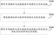
请一并参阅图3,图3为本申请实施例公开的一种显示装置200中连接器组件240的结构示意图。在本申请实施例中,所述连接器组件240至少包括连接器241和补强板245。所述信号传输线220与所述补强板245可通过一体成型的方式制成,即所述信号传输线220与所述补强板245固定连接,所述补强板245和所述信号传输线220均与所述连接器241固定连接。具体地,所述补强板245和所述信号传输线220一体成型后与所述连接器241固定连接,且所述信号传输线220与所述连接器241电性连接,所述连接器241还可所述驱动件250电性连接。也即为,所述信号传输线220通过所述连接器241与所述驱动件250电性连接。Please refer to FIG. 3 together. FIG. 3 is a schematic structural diagram of a
可以理解的是,所述补强板245远离所述信号传输线220的一侧与所述连接器241可以通过例如卡紧、卡合、夹持等方式固定连接,本申请对此不做具体限制。It can be understood that, the side of the reinforcing
在本申请其他实施例中,所述连接器241还包括用于卡紧固定所述补强板245的翻盖(图未标),所述信号传输线220的一侧(即所述信号传输线220的接线处)与所述连接器241固定连接,所述信号传输线220通过所述连接器241与所述驱动件250电性连接,所述补强板245填充所述信号传输线220与所述连接器241之间的空隙,所述信号传输线220和所述补强板245通过所述翻盖与所述连接器241固定连接,从而卡紧固定所述信号传输线220与所述连接器241。其中,可以理解的是,所述信号传输线220的厚度一般小于所述翻盖可以固定的厚度,使得翻盖用于卡紧固定接线端的开口处有缝隙,故所述补强板245的厚度应当填充该缝隙,以使所述补强板245和所述信号传输线220的厚度之和可以被所述翻盖稳定固定。In other embodiments of the present application, the
在本申请另一实施例中,所述连接器组件240至少可以包括连接器241、补强板245和粘接层。所述信号传输线220具有相对的第一面和第二面,所述第二面设置有多个引脚(pin),用于布设电子元器件,所述第一面未设置引脚。所述粘接层设置于所述信号传输线220的第一面,所述补强板245通过所述粘接层与所述信号传输线220的第一面粘接固定,所述信号传输线220和所述补强板245粘接固定后与所述连接器241固定连接。In another embodiment of the present application, the
在本申请具体实施例中,所述连接器241还包括用于卡紧固定补强板245的翻盖(图未标),所述信号传输线220和所述补强板245粘接固定后通过所述翻盖与所述连接器241固定连接。In a specific embodiment of the present application, the
具体地,所述粘接层覆盖所述信号传输线220的第二面的一部分,可以理解的是,所述粘接层覆盖所述信号传输线220的区域的大小由所述信号传输线220与所述补强板245之间的接触面的大小确定,本申请对此不做具体限制。Specifically, the adhesive layer covers a part of the second surface of the
在本申请实施例中,所述粘接层可以为双面胶,所述双面胶包括胶层和分别设置于胶层相对两侧的两个离型层,所述离型层在粘接所述信号传输线220和所述补强板245时剥去。In the embodiment of the present application, the adhesive layer may be a double-sided adhesive tape, and the double-sided adhesive tape includes an adhesive layer and two release layers respectively arranged on opposite sides of the adhesive layer. The
在本申请实施例中,由于所述信号传输线220的厚度一般在0.06毫米(mm)左右,所述连接器241可卡紧固定的接线端的厚度大约在0.3mm,故将所述补强板245设置于所述信号传输线220的表面,使得所述补强板245与所述信号传输线220固定后的厚度可以被所述连接器241稳定固定。In the embodiment of the present application, since the thickness of the
在本申请实施例中,所述信号传输线220及补强板245的材质可为聚乙烯、聚酰亚胺或聚对苯二甲酸乙二醇酯(Polyethylene terephthalate,PET)等,本申请对此不做具体限制。In the embodiment of the present application, the material of the
在本申请实施例中,所述显示面板210和所述驱动件250通过所述连接器组件240和所述信号传输线220实现信号传输,降低了能耗。同时,无需设置电路板,即可减少一道信号传输线与电路板的绑定工艺,不但可以节省制作工艺成本,还节约了在所述显示装置200设置电路板的制作材料成本,提高了生产制造的灵活性和便利性。例如,所述显示面板与电路板通过信号传输线绑定(bonding)连接后,所述信号传输线用外力撕下时易破裂,本申请使用连接器组件240就避免了前述问题,且装拆更加方便,同时很大程度上也降低了品质风险以及信号传输线剥离的发生风险。In the embodiment of the present application, the
基于同一发明构思,本申请还提供了一种显示装置200的组装方法,用于组装图2所示的显示装置200。本申请实施例的显示装置的组装方法涉及到的显示装置的内容,请参照上述实施例中显示装置的相关描述,在此不再赘述。请一并参阅图4,图4为本申请实施例公开的一种显示装置200的组装方法的流程示意图,所述组装方法至少可以包括如下步骤。Based on the same inventive concept, the present application also provides a method for assembling the
步骤S100、将信号传输线220与连接器组件240相固定且电性连接;Step S100, fixing and electrically connecting the
步骤S200、将所述连接器组件240与驱动件250相固定且电性连接;Step S200, fixing and electrically connecting the
步骤S300、将所述信号传输线220与显示面板210电性连接以实现所述显示面板210与所述驱动件250的信号传输。Step S300 , electrically connecting the
在本申请具体实施例中,将所述显示面板210与所述信号传输线220固定连接,进而所述显示面板210通过所述信号传输线220以及所述连接器组件240与所述驱动件250之间实现电性连接,进一步地,所述显示面板210和所述驱动件250实现电性连接和信号传输。In a specific embodiment of the present application, the
请一并参阅图5、图6和图7,图5为图4所示的组装方法中步骤S100的第一实施例的流程示意图。图6为图5所示组装方法的步骤S111对应的结构示意图。图7为图5所示组装方法的步骤S112对应的结构示意图。Please refer to FIG. 5 , FIG. 6 and FIG. 7 together. FIG. 5 is a schematic flowchart of a first embodiment of step S100 in the assembly method shown in FIG. 4 . FIG. 6 is a schematic structural diagram corresponding to step S111 of the assembly method shown in FIG. 5 . FIG. 7 is a schematic structural diagram corresponding to step S112 of the assembly method shown in FIG. 5 .
如图5所示,在本申请一具体实施例中,所述步骤S100至少可以包括如下步骤。As shown in FIG. 5 , in a specific embodiment of the present application, the step S100 may at least include the following steps.
步骤S111、将所述信号传输线220与所述连接器组件240的补强板245一体成型。Step S111 , integrally forming the
如图6所示,在本申请实施例中,所述连接器组件240包括连接器241和补强板245,所述信号传输线220与所述补强板245可通过一体成型的方式制成。As shown in FIG. 6 , in the embodiment of the present application, the
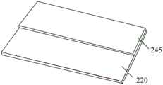
步骤S112、将一体成型的所述补强板245和所述信号传输线220与所述连接器组件240的连接器241固定连接。Step S112 , fixedly connect the integrally formed reinforcing
如图7所示,在本申请实施例中,所述信号传输线220与所述补强板245可通过一体成型的方式制成,即所述信号传输线220与所述补强板245固定连接,所述补强板245和所述信号传输线220均与所述连接器241固定连接。具体地,所述补强板245和所述信号传输线220一体成型后与所述连接器241固定连接,且所述信号传输线220与所述连接器241电性连接,所述连接器241还可与所述驱动件250电性连接。也即为,所述信号传输线220通过所述连接器241与所述驱动件250电性连接。As shown in FIG. 7 , in the embodiment of the present application, the
在本申请具体实施例中,所述补强板245远离所述信号传输线220的一侧与所述连接器241可以通过例如卡紧、卡合、夹持等方式固定连接,本申请对此不做具体限制。In a specific embodiment of the present application, the side of the reinforcing
请一并参阅图8和图9,图8为图4所示的组装方法中步骤S100的第二实施例的流程示意图。图9为图8所示步骤S100中步骤S121对应的结构示意图。如图8所示,在本申请一具体实施例中,所述步骤S100至少可以包括如下步骤。Please refer to FIG. 8 and FIG. 9 together. FIG. 8 is a schematic flowchart of a second embodiment of step S100 in the assembly method shown in FIG. 4 . FIG. 9 is a schematic structural diagram corresponding to step S121 in step S100 shown in FIG. 8 . As shown in FIG. 8 , in a specific embodiment of the present application, the step S100 may at least include the following steps.
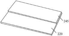
步骤S121、将所述信号传输线220与所述连接器组件240的连接器241固定连接。Step S121 , fixedly connect the
如图9所示,在本申请实施例中,所述连接器组件240包括连接器241,其中,所述信号传输线220的一侧(即所述信号传输线220的接线处)与所述连接器241固定连接。As shown in FIG. 9, in the embodiment of the present application, the
步骤S122、将所述连接器组件240的补强板245填充至所述信号传输线220与所述连接器241之间。Step S122 , filling the reinforcing
在本申请实施例中,所述连接器组件240还包括补强板245,在将所述信号传输线220与所述连接器组件240的连接器241固定连接之后,可将所述连接器组件240的补强板245填充至所述信号传输线220与所述连接器241之间的空隙。In the embodiment of the present application, the
步骤S123、将所述信号传输线220、所述补强板245和所述连接器241通过所述连接器241的翻盖固定连接。Step S123 , fixedly connecting the
在本申请实施例中,所述连接器组件240还包括用于卡紧固定所述补强板245的翻盖(图未标),在所述连接器组件240的补强板245填充至所述信号传输线220与所述连接器241之间的空隙后,即可将所述信号传输线220和所述补强板245通过所述翻盖与所述连接器241固定连接,从而卡紧固定所述信号传输线220与所述连接器241。In the embodiment of the present application, the
请一并参阅图10、图11和图12,图10为图4所示的组装方法中步骤S100的第三实施例的流程示意图。图11为图10所示组装方法的步骤S131对应的结构示意图。图12为图10所示组装方法的步骤S132对应的结构示意图。如图10所示,在本申请一具体实施例中,所述步骤S100至少可以包括如下步骤。Please refer to FIG. 10 , FIG. 11 and FIG. 12 together. FIG. 10 is a schematic flowchart of a third embodiment of step S100 in the assembly method shown in FIG. 4 . FIG. 11 is a schematic structural diagram corresponding to step S131 of the assembly method shown in FIG. 10 . FIG. 12 is a schematic structural diagram corresponding to step S132 of the assembly method shown in FIG. 10 . As shown in FIG. 10 , in a specific embodiment of the present application, the step S100 may at least include the following steps.
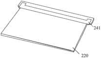
步骤S131、将双面胶246涂覆于所述信号传输线220上。Step S131 , coating the double-
如图11所示,在本申请实施例中,所述连接器组件240包括补强板245,所述信号传输线220具有相对的第一面和第二面,所述第二面设置多个引脚(pin),用于布设电子元器件,所述第一面未设置引脚。所述双面胶246涂覆于所述信号传输线220的第一面,所述双面胶246与所述补强板245粘接冷却后形成所述连接器组件240的粘接层。即所述粘接层设置于所述信号传输线220与所述补强板245之间。As shown in FIG. 11 , in the embodiment of the present application, the
步骤S132、将所述连接器组件240的补强板245通过所述双面胶246与所述信号传输线220粘接固定。Step S132 , bonding and fixing the reinforcing
如图12所示,在本申请实施例中,所述粘接层设置于所述信号传输线220的第二面,所述补强板245通过所述粘接层与所述信号传输线220的第二面粘接固定。As shown in FIG. 12 , in the embodiment of the present application, the adhesive layer is disposed on the second surface of the
步骤S133、将所述信号传输线220和所述补强板245与所述连接器组件240的连接器241固定连接。Step S133 , fixedly connecting the
在本申请实施例中,所述连接器组件240还包括连接器241,所述补强板245通过所述粘接层与所述信号传输线220的第二面粘接固定,所述信号传输线220和所述补强板245与所述连接器241固定连接,以实现所述信号传输线220与所述连接器241固定连接。In the embodiment of the present application, the
在本申请具体实施例中,所述连接器241包括用于卡紧所述补强板245的翻盖(图未标),所述信号传输线220和所述补强板245粘接固定后通过所述翻盖与所述连接器241固定连接。可以理解的是,所述粘接层覆盖所述信号传输线220的区域的大小由所述信号传输线220与所述补强板245之间的接触面的大小确定,本申请对此不做具体限制。In the specific embodiment of the present application, the
在本申请实施例中,所述信号传输线220及补强板245的材质可为聚乙烯、聚酰亚胺、或聚对苯二甲酸乙二醇酯(Polyethylene terephthalate,PET)等,本申请对此不做具体限制。In the embodiment of the present application, the material of the
综上所述,在本申请的显示装置200和组装方法中,设置连接器组件240,通过所述连接器组件240将信号传输线220与所述驱动件250固定连接,且所述显示面板210与信号传输线220电性连接,进而实现显示面板210与所述驱动件250之间的信号传输。To sum up, in the
同时,将现有技术中设置于电路板30上的电子元器件集成设置于所述驱动件250上,而且在所述信号传输线220与所述驱动件250之间无需设置电路板30以布设部分电子元器件,仍然可以实现信号传输及画面显示功能,有效简化了显示装置200的结构,避免了由于增设电路板与显示面板210通过所述信号传输线220电性连接成本较高难度较大,且易造成信号传输线220剥离进而影响信号传输的问题,有效提升了所述显示装置200的显示效果。At the same time, the electronic components arranged on the
对上述实施例中的各个技术特征所有可能的组合都进行描述,然而,只要这些技术特征的组合不存在矛盾,都应当认为是本说明书记载的范围。All possible combinations of the various technical features in the above embodiments are described. However, as long as there is no contradiction in the combination of these technical features, they should be considered as within the scope of this specification.
在本说明书的描述中,参考术语“一个实施方式”、“一些实施方式”、“示意性实施方式”、“示例”、“具体示例”或“一些示例”等的描述意指结合所述实施方式或示例描述的具体特征、结构、材料或者特点包含于本申请的至少一个实施方式或示例中。在本说明书中,对上述术语的示意性表述不一定指的是相同的实施方式或示例。而且,描述的具体特征、结构、材料或者特点可以在任何的一个或多个实施方式或示例中以合适的方式结合。In the description of this specification, reference to the terms "one embodiment", "some embodiments", "exemplary embodiments", "example", "specific examples" or "some examples" etc. The specific features, structures, materials or features described in the manner or example are included in at least one embodiment or example of the present application. In this specification, schematic representations of the above terms do not necessarily refer to the same embodiment or example. Furthermore, the described specific features, structures, materials or characteristics may be combined in any suitable manner in any one or more embodiments or examples.
应当理解的是,以上所述实施例仅表达了本申请的几种实施方式,其描述较为具体和详细,但并不能因此而理解为对申请专利范围的限制。应当指出的是,对于本领域的普通技术人员来说,在不脱离本申请构思的前提下,还可以做出若干变形和改进,这些都属于本申请的保护范围。因此,本申请专利的保护范围应以所附权利要求为准。It should be understood that the above-mentioned embodiments only express several implementation modes of the present application, and the description thereof is relatively specific and detailed, but should not be construed as limiting the scope of the patent application. It should be noted that those skilled in the art can make several modifications and improvements without departing from the concept of the present application, and these all belong to the protection scope of the present application. Therefore, the scope of protection of the patent application should be based on the appended claims.
Claims (10)
Priority Applications (1)
| Application Number | Priority Date | Filing Date | Title |
|---|---|---|---|
| CN202211365565.0ACN115933233A (en) | 2022-10-31 | 2022-10-31 | Display device and assembling method thereof |
Applications Claiming Priority (1)
| Application Number | Priority Date | Filing Date | Title |
|---|---|---|---|
| CN202211365565.0ACN115933233A (en) | 2022-10-31 | 2022-10-31 | Display device and assembling method thereof |
Publications (1)
| Publication Number | Publication Date |
|---|---|
| CN115933233Atrue CN115933233A (en) | 2023-04-07 |
Family
ID=86698341
Family Applications (1)
| Application Number | Title | Priority Date | Filing Date |
|---|---|---|---|
| CN202211365565.0APendingCN115933233A (en) | 2022-10-31 | 2022-10-31 | Display device and assembling method thereof |
Country Status (1)
| Country | Link |
|---|---|
| CN (1) | CN115933233A (en) |
Citations (11)
| Publication number | Priority date | Publication date | Assignee | Title |
|---|---|---|---|---|
| KR20070063746A (en)* | 2005-12-15 | 2007-06-20 | 삼성전자주식회사 | Connector and flat panel display having the same |
| CN101021624A (en)* | 2006-04-18 | 2007-08-22 | 乐金电子(南京)等离子有限公司 | Signal line connecting device and panel display device utilizing signal line connector |
| JP2007294711A (en)* | 2006-04-26 | 2007-11-08 | Optrex Corp | Electronic device, and flexible printed-wiring board |
| KR20090055163A (en)* | 2007-11-28 | 2009-06-02 | 엘지디스플레이 주식회사 | Display device and manufacturing method thereof |
| CN201285648Y (en)* | 2008-09-16 | 2009-08-05 | 奇信电子股份有限公司 | Improved structure of display |
| CN203193088U (en)* | 2013-02-04 | 2013-09-11 | 深圳市得润电子股份有限公司 | LVDS line applied to tablet computer signal transmission |
| CN203351794U (en)* | 2013-07-01 | 2013-12-18 | 艾恩特精密工业股份有限公司 | Side clamshell connector and signal transmission device |
| JP2016127184A (en)* | 2015-01-06 | 2016-07-11 | アール・ビー・コントロールズ株式会社 | Printed wiring board |
| KR20160093445A (en)* | 2015-01-29 | 2016-08-08 | 엘지디스플레이 주식회사 | Display device having flexible printed circuit |
| CN208721945U (en)* | 2018-10-08 | 2019-04-09 | 惠科股份有限公司 | Display device |
| US20190333440A1 (en)* | 2018-04-28 | 2019-10-31 | Xianyang Caihong Optoelectronics Technology Co.,Ltd | Driving device for display panel and display device |
- 2022
- 2022-10-31CNCN202211365565.0Apatent/CN115933233A/enactivePending
Patent Citations (11)
| Publication number | Priority date | Publication date | Assignee | Title |
|---|---|---|---|---|
| KR20070063746A (en)* | 2005-12-15 | 2007-06-20 | 삼성전자주식회사 | Connector and flat panel display having the same |
| CN101021624A (en)* | 2006-04-18 | 2007-08-22 | 乐金电子(南京)等离子有限公司 | Signal line connecting device and panel display device utilizing signal line connector |
| JP2007294711A (en)* | 2006-04-26 | 2007-11-08 | Optrex Corp | Electronic device, and flexible printed-wiring board |
| KR20090055163A (en)* | 2007-11-28 | 2009-06-02 | 엘지디스플레이 주식회사 | Display device and manufacturing method thereof |
| CN201285648Y (en)* | 2008-09-16 | 2009-08-05 | 奇信电子股份有限公司 | Improved structure of display |
| CN203193088U (en)* | 2013-02-04 | 2013-09-11 | 深圳市得润电子股份有限公司 | LVDS line applied to tablet computer signal transmission |
| CN203351794U (en)* | 2013-07-01 | 2013-12-18 | 艾恩特精密工业股份有限公司 | Side clamshell connector and signal transmission device |
| JP2016127184A (en)* | 2015-01-06 | 2016-07-11 | アール・ビー・コントロールズ株式会社 | Printed wiring board |
| KR20160093445A (en)* | 2015-01-29 | 2016-08-08 | 엘지디스플레이 주식회사 | Display device having flexible printed circuit |
| US20190333440A1 (en)* | 2018-04-28 | 2019-10-31 | Xianyang Caihong Optoelectronics Technology Co.,Ltd | Driving device for display panel and display device |
| CN208721945U (en)* | 2018-10-08 | 2019-04-09 | 惠科股份有限公司 | Display device |
Similar Documents
| Publication | Publication Date | Title |
|---|---|---|
| JP3909651B2 (en) | Liquid crystal display device having flexible printed circuit board | |
| US8879021B2 (en) | Liquid crystal display device | |
| US20150085210A1 (en) | In-Cell Touch Liquid Crystal Display Module and Manufacturing Method For The Same | |
| CN108227318B (en) | Method for preventing pin of flexible circuit board from short circuit | |
| KR20110028124A (en) | Liquid crystal display | |
| CN104582263A (en) | Flexible circuit board, assembly method thereof, and display device | |
| WO2019184146A1 (en) | Display panel and display device | |
| EP4012487B1 (en) | Display device and manufacturing method therefor | |
| US8797492B2 (en) | Flexible circuit board | |
| TWI467275B (en) | Display apparatus and assembling/disassembling method thereof | |
| US20060066800A1 (en) | Liquid crystal display device | |
| CN100407019C (en) | Electro-optical devices and electronic equipment | |
| CN115933233A (en) | Display device and assembling method thereof | |
| US10136570B2 (en) | Mounted substrate, mounted-substrate production method, and mounted-substrate production device | |
| JPH1124035A (en) | Liquid crystal display | |
| JPH10221707A (en) | Liquid crystal display | |
| CN108364996A (en) | O L ED display device | |
| CN221485750U (en) | Display panel and display device | |
| US20070052905A1 (en) | Electronic bonding structure with separately distributed anisotropic conductive film units and liquid crystal panel having same | |
| CN116184724A (en) | Display device and assembly method thereof | |
| KR100544817B1 (en) | LCD Module | |
| CN116107123A (en) | Display device and assembly method thereof | |
| CN1826048B (en) | Method for binding IC chip and flexible circuitboard on panel display | |
| WO2010055722A1 (en) | Display apparatus and television receiving apparatus | |
| JP2007078776A (en) | Electrooptical device, manufacturing method for electrooptical device, and electronic equipment |
Legal Events
| Date | Code | Title | Description |
|---|---|---|---|
| PB01 | Publication | ||
| PB01 | Publication | ||
| SE01 | Entry into force of request for substantive examination | ||
| SE01 | Entry into force of request for substantive examination |