CN115931287A - Sectional type ship model and calibration method - Google Patents
Sectional type ship model and calibration methodDownload PDFInfo
- Publication number
- CN115931287A CN115931287ACN202211444286.3ACN202211444286ACN115931287ACN 115931287 ACN115931287 ACN 115931287ACN 202211444286 ACN202211444286 ACN 202211444286ACN 115931287 ACN115931287 ACN 115931287A
- Authority
- CN
- China
- Prior art keywords
- section
- hull
- weight
- ship model
- point
- Prior art date
- Legal status (The legal status is an assumption and is not a legal conclusion. Google has not performed a legal analysis and makes no representation as to the accuracy of the status listed.)
- Pending
Links
Images


Classifications
- Y—GENERAL TAGGING OF NEW TECHNOLOGICAL DEVELOPMENTS; GENERAL TAGGING OF CROSS-SECTIONAL TECHNOLOGIES SPANNING OVER SEVERAL SECTIONS OF THE IPC; TECHNICAL SUBJECTS COVERED BY FORMER USPC CROSS-REFERENCE ART COLLECTIONS [XRACs] AND DIGESTS
- Y02—TECHNOLOGIES OR APPLICATIONS FOR MITIGATION OR ADAPTATION AGAINST CLIMATE CHANGE
- Y02T—CLIMATE CHANGE MITIGATION TECHNOLOGIES RELATED TO TRANSPORTATION
- Y02T90/00—Enabling technologies or technologies with a potential or indirect contribution to GHG emissions mitigation
Landscapes
- Aerodynamic Tests, Hydrodynamic Tests, Wind Tunnels, And Water Tanks (AREA)
Abstract
Description
Translated fromChinese技术领域Technical Field
本发明涉及船模波浪载荷试验与测试技术领域,尤其是一种分段式船模及标定方法。The invention relates to the technical field of ship model wave load test and measurement, in particular to a segmented ship model and a calibration method.
背景技术Background Art
船舶在波浪中航行时会承受较大的波浪载荷,过大的波浪载荷会对船体结构强度构成极大的威胁,确定设计波浪载荷是船舶结构设计的首要工作。恶劣海浪条件下船体波浪载荷会呈现出明显的非线性,理论预报尚不能对其进行精确分析和预报,耐波性水池中分段式船体模型试验是研究船舶波浪载荷最为可靠的方法和手段,测量系统的标定是影响船模波浪载荷试验测量精度的重要步骤。When a ship is sailing in waves, it will be subjected to large wave loads. Excessive wave loads will pose a great threat to the strength of the hull structure. Determining the design wave load is the primary task of ship structure design. Under severe wave conditions, the hull wave load will show obvious nonlinearity, and theoretical predictions cannot accurately analyze and predict it. The segmented hull model test in the wave resistance tank is the most reliable method and means to study the ship wave load. The calibration of the measurement system is an important step that affects the measurement accuracy of the ship model wave load test.
传统的船模波浪载荷试验是在测量梁与船壳组装之前,对测量梁进行标定,获得测量梁各测量剖面弯矩、剪力、扭矩的标定系数,根据该标定系数与正式试验中的测量梁应变信号得到船模波浪载荷。但事实上,测量梁与船壳组装之后,测量梁的初始状态可能会发生变化,会对标定系数带来一定的影响。The traditional ship model wave load test is to calibrate the measuring beam before assembling it with the hull, obtain the calibration coefficients of the bending moment, shear force and torque of each measuring section of the measuring beam, and obtain the ship model wave load based on the calibration coefficient and the strain signal of the measuring beam in the formal test. But in fact, after the measuring beam is assembled with the hull, the initial state of the measuring beam may change, which will have a certain impact on the calibration coefficient.
发明内容Summary of the invention
本申请人针对上述现有生产技术中的缺点,提供一种分段式船模及标定方法,从而实现分段式船模组装后标定,使测量梁的标定系数更加准确,能够更加精确地对波浪载荷进行测量。In view of the shortcomings of the above-mentioned existing production technology, the applicant provides a segmented ship model and a calibration method, so as to realize the calibration of the segmented ship model after assembly, make the calibration coefficient of the measuring beam more accurate, and measure the wave load more precisely.
本发明所采用的技术方案如下:The technical solution adopted by the present invention is as follows:
一种分段式船模,包括分段式船体,所述船体内部的沿船体长度方向设置有测量梁,每段船体对应的测量梁上安装有支撑横梁,支撑横梁的两端与船体的内壁连接,支撑横梁与测量梁相互垂直,每段船体内部还设置有与测量梁轴向垂直的辅助横梁,辅助横梁的两端与船体内壁连接。A segmented ship model comprises a segmented hull, wherein a measuring beam is arranged inside the hull along the length direction of the hull, a supporting crossbeam is installed on the measuring beam corresponding to each segment of the hull, both ends of the supporting crossbeam are connected to the inner wall of the hull, the supporting crossbeam and the measuring beam are perpendicular to each other, and an auxiliary crossbeam perpendicular to the axial direction of the measuring beam is also arranged inside each segment of the hull, and both ends of the auxiliary crossbeam are connected to the inner wall of the hull.
一种分段式船模的标定方法,包括以下步骤:A method for calibrating a segmented ship model comprises the following steps:
第一步、确定测量剖面的位置:Step 1: Determine the location of the measurement section:
测量剖面位于船体分段处,测量剖面的数量为N,当前测量的测量剖面标号为n,n为小于等于N的自然数;The measurement section is located at the hull section, the number of the measurement sections is N, the number of the measurement section currently measured is n, and n is a natural number less than or equal to N;
将应变片粘贴在测量梁的对应位置并与动态应变仪连接;Paste the strain gauge on the corresponding position of the measuring beam and connect it to the dynamic strain gauge;
第二步、确定吊装船模和加载卸载砝码的位置:Step 2: Determine the location for hoisting the ship model and loading and unloading weights:
通过两条吊绳将船模吊起,使船模处于水平状态,吊装位置分别位于船体的首段和尾段,吊绳与首段的连接处为首吊点,吊绳与尾段的连接处为尾吊点;The ship model is hoisted by two hoisting ropes to make it horizontal. The hoisting positions are located at the front and rear sections of the hull respectively. The connection between the hoisting rope and the front section is the front hoisting point, and the connection between the hoisting rope and the rear section is the rear hoisting point.
将砝码放置于船体的中部,砝码距尾吊点的水平距离为l1,砝码距首吊点的水平距离为l2,单次加载卸载砝码的质量为m,首吊点与尾吊点的距离为L;Place the weight in the middle of the hull. The horizontal distance between the weight and the tail lifting point is l1 , and the horizontal distance between the weight and the front lifting point is l2 . The mass of the weight for single loading and unloading is m, and the distance between the front lifting point and the tail lifting point is L.
第三步、计算第n个测量剖面所承受的弯矩Mn:Step 3: Calculate the bending momentMn borne by the nth measurement section:
尾吊点吊绳的拉力为F1The tension of the tail lifting point rope is F1
F1=mgl2L (1)F1 = mgl2 L (1)
首吊点吊绳的拉力为F2The tension of the first lifting point rope isF2
F2=mgl1L (2)F2 = mgl1 L (2)
公式(1)和公式(2)中,g为重力加速度;In formula (1) and formula (2), g is the acceleration due to gravity;
当测量剖面位于尾吊点和加载砝码的位置之间时:When the measuring section is between the tail lifting point and the position where the weight is loaded:
Mn=F1Ln1 (3)Mn =F1Ln1 (3)
公式(3)中,Ln1为第n个测量剖面距离尾吊点的水平距离;In formula (3), Ln1 is the horizontal distance from the nth measurement section to the tail suspension point;
当测量剖面位于首吊点和加载砝码的位置之间时:When the measuring section is between the first lifting point and the position where the weight is loaded:
Mn=F2Ln2 (4)Mn =F2Ln2 (4)
公式(4)中,Ln2为第n个测量剖面距离首吊点的水平距离;In formula (4), Ln2 is the horizontal distance from the nth measurement section to the first hanging point;
第四步、逐次加载卸载砝码,获得每次加载和卸载砝码时第n个测量剖面用于测量弯矩的应变片信号变化量的均值
第五步、计算第n个测量剖面需要标定的弯矩系数δn:Step 5: Calculate the bending moment coefficient δn that needs to be calibrated for the nth measurement section:

其进一步技术方案在于:Its further technical solution is:
第二步中:两条吊绳分别与首段尾段的辅助横梁中部连接,辅助横梁与测量梁轴向垂直,辅助横梁的两端与船体内壁连接,此时船模的船底向下且处于水平状态;第四步中:


第二步中:两条吊绳分别兜住首段尾段的船模外部,与首段尾段的辅助横梁位置相对应,此时船模的侧面向下且处于水平状态;第四步中:


一种分段式船模的标定方法,包括以下步骤:A method for calibrating a segmented ship model comprises the following steps:
第一步、确定测量剖面的位置:Step 1: Determine the location of the measurement section:
测量剖面位于船体分段处,测量剖面的数量为N,当前测量的测量剖面标号为n,n为小于等于N的自然数;The measurement section is located at the hull section, the number of the measurement sections is N, the number of the measurement section currently measured is n, and n is a natural number less than or equal to N;
将应变片粘贴在测量梁的对应位置并与动态应变仪连接;Paste the strain gauge on the corresponding position of the measuring beam and connect it to the dynamic strain gauge;
第二步、确定吊装船模和加载卸载砝码的位置:Step 2: Determine the location for hoisting the ship model and loading and unloading weights:
吊装位置为多个且沿船体纵向均匀分布,吊装位置包括船体的首段和尾段,多条吊绳分别与对应的分段船体的辅助横梁中部连接,辅助横梁与测量梁轴向垂直,辅助横梁的两端与船体内壁连接,使船模的船底向下且处于水平状态;There are multiple lifting positions evenly distributed along the longitudinal direction of the hull, including the fore and stern sections of the hull. Multiple lifting ropes are respectively connected to the middle of the auxiliary beams of the corresponding segmented hulls. The auxiliary beams are axially perpendicular to the measuring beams, and both ends of the auxiliary beams are connected to the inner wall of the hull, so that the bottom of the ship model is downward and in a horizontal state.
将砝码加载位置为船体的首段和尾段,使首段和尾段受到方向相反的作用力,通过单次加载或卸载相同质量砝码的方式,使单次加载砝码时在船体剖面处承受扭矩T大小不变;The weights are loaded at the fore and stern sections of the hull, so that the fore and stern sections are subjected to forces in opposite directions. By loading or unloading weights of the same mass at a single time, the magnitude of the torque T borne at the hull section remains unchanged when the weights are loaded at a single time.
第三步、逐次加载卸载砝码,获得每次加载和卸载砝码时第n个测量剖面用于测量扭矩的应变片信号变化量的均值
第四步、计算第n个测量剖面需要标定的扭转系数δCn:Step 4: Calculate the torsion coefficient δCn required for calibration of the nth measurement profile:

其进一步技术方案在于:Its further technical solution is:
第二步中:In the second step:
在船体的尾段外部设置第一钢制框架,在首段外部设置第二钢制框架,A first steel frame is arranged outside the tail section of the hull, and a second steel frame is arranged outside the front section.
在位于船体左舷侧的第一钢制框架一端通过第一柔性连接线连接第一砝码,在位于船体右舷侧的第一钢制框架一端通过第二柔性连接线连接第二砝码,第一柔性连接线和第二柔性连接线与第一钢制框架的连接点与吊绳之间的距离均为l5,第一柔性连接线竖直向下连接第一砝码,第二柔性连接线竖直向上后与定滑轮配合后再竖直向下连接第二砝码;A first weight is connected to one end of a first steel frame located on the port side of the hull through a first flexible connecting line, and a second weight is connected to one end of the first steel frame located on the starboard side of the hull through a second flexible connecting line. The distance between the connection point of the first flexible connecting line and the second flexible connecting line with the first steel frame and the suspension rope is 15, the first flexible connecting line is vertically downwardly connected to the first weight, and the second flexible connecting line is vertically upwardly matched with a fixed pulley and then vertically downwardly connected to the second weight;
在位于船体右舷侧的第二钢制框架一端通过第三柔性连接线连接第三砝码,在位于船体左舷侧的第二钢制框架一端通过第四柔性连接线连接第四砝码,第三柔性连接线和第四柔性连接线与第二钢制框架的连接点与吊绳之间的距离均为l5,第三柔性连接线竖直向下连接第三砝码,第四柔性连接线竖直向上后与定滑轮配合后竖直向下连接第四砝码;A third weight is connected to one end of the second steel frame on the starboard side of the hull through a third flexible connecting line, and a fourth weight is connected to one end of the second steel frame on the port side of the hull through a fourth flexible connecting line. The distances between the connection points of the third and fourth flexible connecting lines with the second steel frame and the suspension rope are both 15. The third flexible connecting line is connected to the third weight vertically downward, and the fourth flexible connecting line is connected to the fourth weight vertically downward after being connected to the fixed pulley after being connected to the fixed pulley vertically upward.
第一砝码、第二砝码、第三砝码和第四砝码单次加载和卸载的质量均为m,T=2mgl5。The masses of the first weight, the second weight, the third weight and the fourth weight loaded and unloaded at a single time are all m, and T = 2 mgl5 .
吊绳与首段的连接处为首吊点,吊绳与尾段连接处为尾吊点,首段和尾段砝码加载位置均位于吊绳外侧。The connection between the lifting rope and the first section is the first lifting point, and the connection between the lifting rope and the last section is the last lifting point. The weight loading positions of the first section and the last section are both located outside the lifting rope.
尾吊点与第一钢质框架之间的距离为l3,首吊点与第二钢质框架之间的距离为l4,l3和l4的尺寸范围均为30cm~40cm。The distance between the tail hanging point and the first steel frame is l3 , and the distance between the head hanging point and the second steel frame is l4 . The size ranges of l3 and l4 are both 30 cm to 40 cm.
本发明的有益效果如下:The beneficial effects of the present invention are as follows:
本发明结构紧凑、合理,操作方便,通过在分段式船模上设置用于吊装用的辅助横梁,通过不同的悬吊方式对分段式船模垂向弯矩系数、水平弯矩系数、扭转系数进行标定,实现分段式船模组装后标定,使测量梁的标定系数更加准确,能够更加精确地对波浪载荷进行测量。The present invention has a compact and reasonable structure and is easy to operate. An auxiliary crossbeam for hoisting is arranged on the segmented ship model, and the vertical bending moment coefficient, horizontal bending moment coefficient and torsion coefficient of the segmented ship model are calibrated through different suspension methods. The segmented ship model is calibrated after assembly, so that the calibration coefficient of the measuring beam is more accurate, and the wave load can be measured more accurately.
同时,本发明还存在如下优势:At the same time, the present invention also has the following advantages:
(1)本发明可实现测量梁与船体外壳装配之后的垂向弯矩系数、水平弯矩系数、扭矩系数的标定,该状态下的标定系数更加符合实际情况,可获得更加精确的波浪载荷试验测量结果。(1) The present invention can realize the calibration of the vertical bending moment coefficient, horizontal bending moment coefficient and torque coefficient after the measurement beam is assembled with the hull shell. The calibration coefficients in this state are more in line with the actual situation, and more accurate wave load test measurement results can be obtained.
(2)本发明的标定方法可同时对所有测量剖面的垂向弯矩系数、水平弯矩系数、扭矩系数进行标定,标定效率高,操作简单。(2) The calibration method of the present invention can calibrate the vertical bending moment coefficient, horizontal bending moment coefficient, and torque coefficient of all measurement sections at the same time, with high calibration efficiency and simple operation.
(3)标定扭矩系数时,通过在船模中纵剖面布置系列吊点将船模吊起,在船模首段和船模尾段施加大小相等方向相反的扭矩,一方面该方法使得各剖面承受的扭矩大小是相等的,可实现各剖面扭矩系数的同时标定,另一方面该方法确保了该悬吊状态下船模承受的外部载荷只包含扭矩,最大程度减少了标定过程中的不确定因素,提高了标定精度。(3) When calibrating the torque coefficient, the ship model is hoisted by arranging a series of lifting points in the longitudinal section of the ship model, and torques of equal magnitude and opposite directions are applied to the fore and stern sections of the ship model. On the one hand, this method makes the torques borne by each section equal, and the torque coefficients of each section can be calibrated simultaneously. On the other hand, this method ensures that the external load borne by the ship model in the suspended state only includes torque, which minimizes the uncertainty factors in the calibration process and improves the calibration accuracy.
附图说明BRIEF DESCRIPTION OF THE DRAWINGS
图1为本发明标定垂向弯矩系数时的结构示意图。FIG. 1 is a schematic diagram of the structure of the present invention when calibrating the vertical bending moment coefficient.
图2为本发明标定水平弯矩系数时的结构示意图。FIG. 2 is a schematic diagram of the structure of the present invention when calibrating the horizontal bending moment coefficient.
图3为图2的侧视图。FIG. 3 is a side view of FIG. 2 .
图4为本发明标定扭转系数时的结构示意图。FIG. 4 is a schematic diagram of the structure of the present invention when calibrating the torsion coefficient.
图5为图4中A-A截面的剖视图。FIG5 is a cross-sectional view of the A-A section in FIG4.
图6为图4中B-B截面的剖视图。FIG6 is a cross-sectional view of the B-B section in FIG4.
其中:a、船体;b、测量梁;c、支撑横梁;d、辅助横梁;e、砝码;e1、第一砝码;e2、第二砝码;e3、第三砝码;e4、第四砝码;f、吊绳;G1、第一钢质框架;G2、第二钢质框架。Among them: a, hull; b, measuring beam; c, supporting beam; d, auxiliary beam; e, weights; e1, first weight; e2, second weight; e3, third weight; e4, fourth weight; f, lifting rope; G1, first steel frame; G2, second steel frame.
具体实施方式DETAILED DESCRIPTION
下面结合附图,说明本发明的具体实施方式。The specific implementation of the present invention is described below in conjunction with the accompanying drawings.
如图1-图2所示,实施例一的分段式船模,其特征在于:包括分段式船体a,所述船体a内部的沿船体a长度方向设置有测量梁b,每段船体对应的测量梁b上安装有支撑横梁c,支撑横梁c的两端与船体a的内壁连接,支撑横梁c与测量梁b相互垂直,每段船体内部还设置有与测量梁b轴向垂直的辅助横梁d,辅助横梁d的两端与船体a内壁连接。As shown in Figures 1 and 2, the segmented ship model of Example 1 is characterized in that it includes a segmented hull a, a measuring beam b is arranged inside the hull a along the length direction of the hull a, a supporting beam c is installed on the measuring beam b corresponding to each segment of the hull, both ends of the supporting beam c are connected to the inner wall of the hull a, the supporting beam c and the measuring beam b are perpendicular to each other, and an auxiliary beam d is also arranged inside each segment of the hull and is axially perpendicular to the measuring beam b, and both ends of the auxiliary beam d are connected to the inner wall of the hull a.
设置辅助横梁d作为组装后分段式船模在测量测量梁b的垂向弯矩系数和扭转系数时的吊装位置,使测量梁b的状态下更加符合实际情况且不受吊装的影响。The auxiliary beam d is set as the hoisting position of the assembled segmented ship model when measuring the vertical bending moment coefficient and torsion coefficient of the measuring beam b, so that the state of the measuring beam b is more in line with the actual situation and is not affected by the hoisting.
如图1-图3所示,实施例二的分段式船模的标定方法,包括以下步骤:As shown in FIGS. 1 to 3 , the calibration method of the segmented ship model of the second embodiment includes the following steps:
第一步、确定测量剖面的位置:Step 1: Determine the location of the measurement section:
测量剖面位于船体a分段处,测量剖面的数量为N,当前测量的测量剖面标号为n,n为小于等于N的自然数;The measurement section is located at the section a of the hull, the number of measurement sections is N, the number of the measurement section currently measured is n, and n is a natural number less than or equal to N;
将应变片粘贴在测量梁b的对应位置并与动态应变仪连接;Paste the strain gauge at the corresponding position of the measuring beam b and connect it to the dynamic strain gauge;
第二步、确定吊装船模和加载卸载砝码的位置:Step 2: Determine the location for hoisting the ship model and loading and unloading weights:
通过两条吊绳f将船模吊起,使船模处于水平状态,吊装位置分别位于船体a的首段和尾段,吊绳f与首段的连接处为首吊点,吊绳f与尾段的连接处为尾吊点;将两处吊绳f分别设置在首段和尾段,并分别与首段和尾段的辅助横梁d位置对应,可测量所有的测量剖面的数据;The ship model is hoisted by two hoisting ropes f so that the ship model is in a horizontal state. The hoisting positions are respectively located at the front section and the rear section of the hull a. The connection between the hoisting rope f and the front section is the front hoisting point, and the connection between the hoisting rope f and the rear section is the rear hoisting point. The two hoisting ropes f are respectively set at the front section and the rear section, and correspond to the positions of the auxiliary beams d of the front section and the rear section respectively, so that the data of all the measurement sections can be measured;
将砝码e放置于船体的中部,砝码e距尾吊点的水平距离为l1,砝码e距首吊点的水平距离为l2,单次加载卸载砝码的质量为m,首吊点与尾吊点的距离为L;Place the weight e in the middle of the hull. The horizontal distance between the weight e and the tail lifting point is l1 , and the horizontal distance between the weight e and the front lifting point is l2 . The mass of the weight for single loading and unloading is m, and the distance between the front lifting point and the tail lifting point is L.
第三步、计算第n个测量剖面所承受的弯矩Mn:Step 3: Calculate the bending moment Mn borne by the nth measurement section:
尾吊点吊绳f的拉力为F1The tension of the tail suspension point rope f is F1
F1=mgl2L (1)F1 = mgl2 L (1)
首吊点吊绳f的拉力为F2The tension of the first lifting point rope f is F2
F2=mgl1L (2)F2 = mgl1 L (2)
公式(1)和公式(2)中,g为重力加速度;In formula (1) and formula (2), g is the acceleration due to gravity;
当测量剖面位于尾吊点和加载砝码e的位置之间时:When the measuring section is between the tail suspension point and the position of the loading weight e:
Mn=F1Ln1 (3)Mn =F1Ln1 (3)
公式(3)中,Ln1为第n个测量剖面距离尾吊点的水平距离;In formula (3), Ln1 is the horizontal distance from the nth measurement section to the tail suspension point;
当测量剖面位于首吊点和加载砝码e的位置之间时:When the measuring section is between the first lifting point and the position of the loading weight e:
Mn=F2Ln2 (4)Mn =F2Ln2 (4)
公式(4)中,Ln2为第n个测量剖面距离首吊点的水平距离;In formula (4), Ln2 is the horizontal distance from the nth measurement section to the first hanging point;
第四步、逐次加载卸载砝码,获得每次加载和卸载砝码时第n个测量剖面用于测量弯矩的应变片信号变化量的均值
第五步、计算第n个测量剖面需要标定的弯矩系数δn:Step 5: Calculate the bending moment coefficient δn that needs to be calibrated for the nth measurement section:

如图1所示,实施例三的分段式船模的标定方法,包括以下步骤:As shown in FIG1 , the calibration method of the segmented ship model of the third embodiment includes the following steps:
第一步、确定测量剖面的位置:Step 1: Determine the location of the measurement section:
测量剖面位于船体a分段处,测量剖面的数量为N,当前测量的测量剖面标号为n,n为小于等于N的自然数;The measurement section is located at the section a of the hull, the number of measurement sections is N, the number of the measurement section currently measured is n, and n is a natural number less than or equal to N;
将应变片粘贴在测量梁b的对应位置并与动态应变仪连接;Paste the strain gauge at the corresponding position of the measuring beam b and connect it to the dynamic strain gauge;
第二步、确定吊装船模和加载卸载砝码的位置:Step 2: Determine the location for hoisting the ship model and loading and unloading weights:
两条吊绳f分别与首段尾段的辅助横梁d中部连接,辅助横梁d与测量梁b轴向垂直,辅助横梁d的两端与船体a内壁连接,此时船模的船底向下且处于水平状态;吊绳f与首段的连接处为首吊点,吊绳f与尾段的连接处为尾吊点,首吊点和尾吊点位于船体a的纵剖面处;Two lifting ropes f are connected to the middle of the auxiliary beam d of the first section and the last section respectively. The auxiliary beam d is axially perpendicular to the measuring beam b. Both ends of the auxiliary beam d are connected to the inner wall of the hull a. At this time, the bottom of the ship model is facing downward and in a horizontal state. The connection between the lifting rope f and the first section is the first lifting point, and the connection between the lifting rope f and the last section is the last lifting point. The first lifting point and the last lifting point are located at the longitudinal section of the hull a.
将砝码e放置于船体的中部,砝码e距尾吊点的水平距离为l1,砝码e距首吊点的水平距离为l2,单次加载卸载砝码的质量为m,首吊点与尾吊点的距离为L;Place the weight e in the middle of the hull. The horizontal distance between the weight e and the tail lifting point is l1 , and the horizontal distance between the weight e and the front lifting point is l2 . The mass of the weight for single loading and unloading is m, and the distance between the front lifting point and the tail lifting point is L.
第三步、计算第n个测量剖面所承受的弯矩Mn:Step 3: Calculate the bending momentMn borne by the nth measurement section:
尾吊点吊绳f的拉力为F1The tension of the tail suspension point rope f is F1
F1=mgl2L (1)F1 = mgl2 L (1)
首吊点吊绳f的拉力为FxThe tension of the first lifting point rope f is Fx
F2=mgl1L (2)F2 = mgl1 L (2)
公式(1)和公式(2)中,g为重力加速度;In formula (1) and formula (2), g is the acceleration due to gravity;
当测量剖面位于尾吊点和加载砝码e的位置之间时:When the measuring section is between the tail suspension point and the position of the loading weight e:
Mn=F1Ln1 (3)Mn =F1Ln1 (3)
公式(3)中,Ln1为第n个测量剖面距离尾吊点的水平距离;In formula (3), Ln1 is the horizontal distance from the nth measurement section to the tail suspension point;
当测量剖面位于首吊点和加载砝码e的位置之间时:When the measuring section is between the first lifting point and the position of the loading weight e:
Mn=F2Ln2 (4)Mn =F2Ln2 (4)
公式(4)中,Ln2为第n个测量剖面距离首吊点的水平距离;In formula (4), Ln2 is the horizontal distance from the nth measurement section to the first hanging point;
第四步、逐次加载卸载砝码,获得每次加载和卸载砝码时第n个测量剖面用于测量弯矩的应变片信号变化量的均值


第五步、计算第n个测量剖面需要标定的弯矩系数δn:Step 5: Calculate the bending moment coefficient δn required for calibration of the nth measurement section:
δx即为第n个测量剖面需要标定的垂向弯矩系数δAn,
如图2-图3所示,实施例四的分段式船模的标定方法,包括以下步骤:As shown in FIG. 2-FIG 3, the calibration method of the segmented ship model of the fourth embodiment includes the following steps:
第一步、确定测量剖面的位置:The first step is to determine the location of the measurement section:
测量剖面位于船体a分段处,测量剖面的数量为N,当前测量的测量剖面标号为n,n为小于等于N的自然数;The measurement section is located at the section a of the hull, the number of measurement sections is N, the number of the measurement section currently measured is n, and n is a natural number less than or equal to N;
将应变片粘贴在测量梁b的对应位置并与动态应变仪连接;Paste the strain gauge at the corresponding position of the measuring beam b and connect it to the dynamic strain gauge;
第二步、确定吊装船模和加载卸载砝码的位置:Step 2: Determine the location for hoisting the ship model and loading and unloading weights:
通过两条吊绳f分别兜住首段尾段的船模外部,与首段尾段的辅助横梁d位置相对应,此时船模的侧面向下且处于水平状态;吊绳f与首段的连接处为首吊点,吊绳f与尾段的连接处为尾吊点;Two lifting ropes f are used to respectively hold the exterior of the first and last sections of the ship model, corresponding to the position of the auxiliary crossbeam d of the first and last sections. At this time, the side of the ship model is downward and in a horizontal state; the connection between the lifting rope f and the first section is the first lifting point, and the connection between the lifting rope f and the last section is the last lifting point;
将砝码e放置于船体的中部,砝码e距尾吊点的水平距离为l1,砝码e距首吊点的水平距离为l2,单次加载卸载砝码的质量为m,首吊点与尾吊点的距离为L;Place the weight e in the middle of the hull. The horizontal distance between the weight e and the tail lifting point is l1 , and the horizontal distance between the weight e and the front lifting point is l2 . The mass of the weight for single loading and unloading is m, and the distance between the front lifting point and the tail lifting point is L.
第三步、计算第n个测量剖面所承受的弯矩Mn:Step 3: Calculate the bending momentMn borne by the nth measurement section:
尾吊点吊绳f的拉力为F1The tension of the tail suspension point rope f is F1
F1=mgl2L (1)F1 = mgl2 L (1)
首吊点吊绳f的拉力为F2The tension of the first lifting point rope f is F2
F2=mgl1L (2)F2 = mgl1 L (2)
公式(1)和公式(2)中,g为重力加速度;In formula (1) and formula (2), g is the acceleration due to gravity;
当测量剖面位于尾吊点和加载砝码e的位置之间时:When the measuring section is between the tail suspension point and the position of the loading weight e:
Mn=F1Ln1 (3)Mn =F1Ln1 (3)
公式(3)中,Ln1为第n个测量剖面距离尾吊点的水平距离;In formula (3), Ln1 is the horizontal distance from the nth measurement section to the tail suspension point;
当测量剖面位于首吊点和加载砝码e的位置之间时:When the measuring section is between the first lifting point and the position of the loading weight e:
Mn=F2Ln2 (4)Mn =F2Ln2 (4)
公式(4)中,Ln2为第n个测量剖面距离首吊点的水平距离;In formula (4), Ln2 is the horizontal distance from the nth measurement section to the first hanging point;
第四步、逐次加载卸载砝码,获得每次加载和卸载砝码时第n个测量剖面用于测量弯矩的应变片信号变化量的均值


第五步、计算第n个测量剖面需要标定的弯矩系数δn:Step 5: Calculate the bending moment coefficientδn that needs to be calibrated for the nth measurement section:
δn即为第n个测量剖面需要标定的水平弯矩系数δBn,
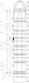
如图4-图6所示,实施例五的分段式船模的标定方法,包括以下步骤:As shown in FIGS. 4 to 6 , the calibration method of the segmented ship model of the fifth embodiment includes the following steps:
第一步、确定测量剖面的位置:Step 1: Determine the location of the measurement section:
测量剖面位于船体a分段处,测量剖面的数量为N,当前测量的测量剖面标号为n,n为小于等于N的自然数;The measurement section is located at the section a of the hull, the number of measurement sections is N, the number of the measurement section currently measured is n, and n is a natural number less than or equal to N;
将应变片粘贴在测量梁b的对应位置并与动态应变仪连接;Paste the strain gauge at the corresponding position of the measuring beam b and connect it to the dynamic strain gauge;
第二步、确定吊装船模和加载卸载砝码的位置:Step 2: Determine the location for hoisting the ship model and loading and unloading weights:
吊装位置为多个且沿船体a纵向均匀分布,吊装位置包括船体a的首段和尾段,多条吊绳f分别与对应的分段船体的辅助横梁d中部连接,辅助横梁d与测量梁b轴向垂直,辅助横梁d的两端与船体a内壁连接,使船模的船底向下且处于水平状态,吊点位于船体a的纵剖面处;There are multiple lifting positions evenly distributed along the longitudinal direction of the hull a. The lifting positions include the fore and stern sections of the hull a. Multiple lifting ropes f are respectively connected to the middle of the auxiliary beam d of the corresponding segmented hull. The auxiliary beam d is axially perpendicular to the measuring beam b. Both ends of the auxiliary beam d are connected to the inner wall of the hull a, so that the bottom of the ship model is facing downward and in a horizontal state. The lifting point is located at the longitudinal section of the hull a.
将砝码e加载位置为船体a的首段和尾段,使首段和尾段受到方向相反的作用力,通过单次加载或卸载相同质量砝码的方式,使单次加载砝码时在船体剖面处承受扭矩T大小不变;The weight e is loaded at the fore and stern sections of the hull a, so that the fore and stern sections are subjected to forces in opposite directions. By loading or unloading the weight of the same mass once, the torque T borne at the hull section remains unchanged when the weight is loaded once;
一方面该方法使得各测量剖面承受的扭矩大小是相等的,可实现各测量剖面扭矩系数的同时标定,另一方面该方法确保了该悬吊状态下船体a及测量梁b承受的外部载荷只包含扭矩,最大程度减少了标定过程中的不确定因素,提高了标定精度;On the one hand, this method makes the torque borne by each measurement section equal, and can realize the simultaneous calibration of the torque coefficient of each measurement section. On the other hand, this method ensures that the external load borne by the hull a and the measurement beam b in the suspended state only includes the torque, which minimizes the uncertainty factors in the calibration process and improves the calibration accuracy.
第三步、逐次加载卸载砝码,获得每次加载和卸载砝码时第n个测量剖面用于测量扭矩的应变片信号变化量的均值
第四步、计算第n个测量剖面需要标定的扭转系数δCn:Step 4: Calculate the torsion coefficient δCn required for calibration of the nth measurement profile:

如图4-图6所示,实施例六的分段式船模的标定方法,包括以下步骤:As shown in FIGS. 4 to 6 , the calibration method of the segmented ship model of the sixth embodiment includes the following steps:
第一步、确定测量剖面的位置:Step 1: Determine the location of the measurement section:
测量剖面位于船体a分段处,测量剖面的数量为N,当前测量的测量剖面标号为n,n为小于等于N的自然数;The measurement section is located at the section a of the hull, the number of measurement sections is N, the number of the measurement section currently measured is n, and n is a natural number less than or equal to N;
将应变片粘贴在测量梁b的对应位置并与动态应变仪连接;Paste the strain gauge at the corresponding position of the measuring beam b and connect it to the dynamic strain gauge;
第二步、确定吊装船模和加载卸载砝码的位置:Step 2: Determine the location for hoisting the ship model and loading and unloading weights:
吊装位置为多个且沿船体a纵向均匀分布,吊装位置包括船体a的首段和尾段,多条吊绳f分别与对应的分段船体的辅助横梁d中部连接,辅助横梁d与测量梁b轴向垂直,辅助横梁d的两端与船体a内壁连接,使船模的船底向下且处于水平状态,吊点位于船体a的纵剖面处;There are multiple lifting positions evenly distributed along the longitudinal direction of the hull a. The lifting positions include the fore and stern sections of the hull a. Multiple lifting ropes f are respectively connected to the middle of the auxiliary beam d of the corresponding segmented hull. The auxiliary beam d is axially perpendicular to the measuring beam b. Both ends of the auxiliary beam d are connected to the inner wall of the hull a, so that the bottom of the ship model is facing downward and in a horizontal state. The lifting point is located at the longitudinal section of the hull a.
在船体a的尾段外部设置第一钢制框架G1,在首段外部设置第二钢制框架G2,在位于船体a左舷侧的第一钢制框架G1一端通过第一柔性连接线连接第一砝码e1,在位于船体a右舷侧的第一钢制框架G1一端通过第二柔性连接线连接第二砝码e2,第一柔性连接线和第二柔性连接线与第一钢制框架G1的连接点与吊绳f之间的距离均为l5,第一柔性连接线竖直向下连接第一砝码e1,第二柔性连接线竖直向上后与定滑轮i配合后再竖直向下连接第二砝码e2;A first steel frame G1 is arranged outside the tail section of the hull a, and a second steel frame G2 is arranged outside the front section. One end of the first steel frame G1 located on the port side of the hull a is connected to the first weight e1 through a first flexible connecting line, and one end of the first steel frame G1 located on the starboard side of the hull a is connected to the second weight e2 through a second flexible connecting line. The distances between the connection points of the first flexible connecting line and the second flexible connecting line with the first steel frame G1 and the suspension rope f are both 15 . The first flexible connecting line is connected to the first weight e1 vertically downward, and the second flexible connecting line is connected to the second weight e2 vertically downward after being connected to the fixed pulley i vertically upward;
在位于船体a右舷侧的第二钢制框架G2一端通过第三柔性连接线连接第三砝码e3,在位于船体a左舷侧的第二钢制框架G2一端通过第四柔性连接线连接第四砝码e4,第三柔性连接线和第四柔性连接线与第二钢制框架G2的连接点与吊绳f之间的距离均为l5,第三柔性连接线竖直向下连接第三砝码e3,第四柔性连接线竖直向上后与定滑轮i配合后竖直向下连接第四砝码e4;A third weight e3 is connected to one end of the second steel frame G2 located on the starboard side of the hull a through a third flexible connecting line, and a fourth weight e4 is connected to one end of the second steel frame G2 located on the port side of the hull a through a fourth flexible connecting line. The distances between the connection points of the third and fourth flexible connecting lines with the second steel frame G2 and the suspension rope f are both l5 . The third flexible connecting line is vertically downwardly connected to the third weight e3, and the fourth flexible connecting line is vertically upwardly matched with the fixed pulley i and then vertically downwardly connected to the fourth weight e4;
第一砝码e1、第二砝码e2、第三砝码e3和第四砝码e4单次加载和卸载的质量均为m,T=2mgl5;The mass of the first weight e1, the second weight e2, the third weight e3 and the fourth weight e4 for single loading and unloading is m, T = 2 mgl5 ;
通过第一钢制框架G1、第二钢制框架G2配合定滑轮i使用,在首段和尾段施加方向相反的作用力,通过单次加载或卸载相同质量砝码的方式,使单次加载砝码时船体剖面处承受扭矩T大小不变,使操作更加方便;The first steel frame G1 and the second steel frame G2 are used in conjunction with the fixed pulley i to apply forces in opposite directions to the front section and the rear section. By loading or unloading the same mass weights at a single time, the torque T borne by the hull section remains unchanged when the weights are loaded at a single time, making the operation more convenient.
第三步、逐次加载卸载砝码,获得每次加载和卸载砝码时第n个测量剖面用于测量扭矩的应变片信号变化量的均值
第四步、计算第n个测量剖面需要标定的扭转系数δCn:Step 4: Calculate the torsion coefficient δCn required for calibration of the nth measurement profile:

本实施例六中,吊绳f与首段的连接处为首吊点,吊绳f与尾段连接处为尾吊点,首段和尾段砝码e加载位置均位于吊绳f外侧,在该部位加载砝码可测量所有的测量剖面的数据。In this sixth embodiment, the connection between the lifting rope f and the first section is the first lifting point, and the connection between the lifting rope f and the tail section is the tail lifting point. The loading positions of the weights e of the first and tail sections are both located outside the lifting rope f. Loading weights at this position can measure the data of all measurement profiles.
尾吊点与第一钢质框架G1之间的距离为l3,首吊点与第二钢质框架G2之间的距离为l4,l3和l4的尺寸范围均为30cm~40cm,保证施加载荷位置的有效性。The distance between the tail hanging point and the first steel frame G1 is l3 , and the distance between the head hanging point and the second steel frame G2 is l4 . The size ranges of l3 and l4 are both 30 cm to 40 cm, ensuring the effectiveness of the load application position.
本发明可实现测量梁b与船体a外壳装配之后的垂向弯矩系数、水平弯矩系数、扭矩系数的标定,该状态下的标定系数更加符合实际情况,可获得更加精确的波浪载荷试验测量结果,并可同时对所有测量剖面的垂向弯矩系数、水平弯矩系数、扭矩系数进行标定,标定效率高,操作简单。The present invention can realize the calibration of the vertical bending moment coefficient, the horizontal bending moment coefficient and the torque coefficient after the measurement beam b is assembled with the outer shell of the hull a. The calibration coefficient in this state is more in line with the actual situation, and a more accurate wave load test measurement result can be obtained. The vertical bending moment coefficient, the horizontal bending moment coefficient and the torque coefficient of all measurement sections can be calibrated at the same time, and the calibration efficiency is high and the operation is simple.
以上描述是对本发明的解释,不是对发明的限定,本发明所限定的范围参见权利要求,在本发明的保护范围之内,可以作任何形式的修改。The above description is an explanation of the present invention, not a limitation of the present invention. The scope of the present invention is defined in the claims. Any form of modification may be made within the scope of protection of the present invention.
Claims (8)
Translated fromChinese


Priority Applications (1)
| Application Number | Priority Date | Filing Date | Title |
|---|---|---|---|
| CN202211444286.3ACN115931287A (en) | 2022-11-18 | 2022-11-18 | Sectional type ship model and calibration method |
Applications Claiming Priority (1)
| Application Number | Priority Date | Filing Date | Title |
|---|---|---|---|
| CN202211444286.3ACN115931287A (en) | 2022-11-18 | 2022-11-18 | Sectional type ship model and calibration method |
Publications (1)
| Publication Number | Publication Date |
|---|---|
| CN115931287Atrue CN115931287A (en) | 2023-04-07 |
Family
ID=86654888
Family Applications (1)
| Application Number | Title | Priority Date | Filing Date |
|---|---|---|---|
| CN202211444286.3APendingCN115931287A (en) | 2022-11-18 | 2022-11-18 | Sectional type ship model and calibration method |
Country Status (1)
| Country | Link |
|---|---|
| CN (1) | CN115931287A (en) |
Citations (3)
| Publication number | Priority date | Publication date | Assignee | Title |
|---|---|---|---|---|
| CN103033314A (en)* | 2012-12-24 | 2013-04-10 | 中国船舶重工集团公司第七○二研究所 | Torsion calibration device and method for measurement beam used for ship model wave load test |
| CN106546408A (en)* | 2016-11-04 | 2017-03-29 | 中国船舶科学研究中心(中国船舶重工集团公司第七0二研究所) | Measuring beam calibration device for ship wave load test |
| CN110371242A (en)* | 2019-08-05 | 2019-10-25 | 中国船舶科学研究中心(中国船舶重工集团公司第七0二研究所) | A kind of standard ship model suitable for a variety of measuring systems |
- 2022
- 2022-11-18CNCN202211444286.3Apatent/CN115931287A/enactivePending
Patent Citations (3)
| Publication number | Priority date | Publication date | Assignee | Title |
|---|---|---|---|---|
| CN103033314A (en)* | 2012-12-24 | 2013-04-10 | 中国船舶重工集团公司第七○二研究所 | Torsion calibration device and method for measurement beam used for ship model wave load test |
| CN106546408A (en)* | 2016-11-04 | 2017-03-29 | 中国船舶科学研究中心(中国船舶重工集团公司第七0二研究所) | Measuring beam calibration device for ship wave load test |
| CN110371242A (en)* | 2019-08-05 | 2019-10-25 | 中国船舶科学研究中心(中国船舶重工集团公司第七0二研究所) | A kind of standard ship model suitable for a variety of measuring systems |
Non-Patent Citations (2)
| Title |
|---|
| 候家怡: "大型集装箱船船体梁波激振动响应特性研究", 中国优秀硕士学位论文全文数据库, 15 January 2020 (2020-01-15), pages 51 - 53* |
| 司海龙 等: "船模波浪载荷试验不确定度分析方法研究", 船舶力学, vol. 26, no. 2, 28 February 2022 (2022-02-28), pages 202 - 214* |
Similar Documents
| Publication | Publication Date | Title |
|---|---|---|
| CN103033314B (en) | Torsion calibration method for measurement beam used for ship model wave load test | |
| CN109141820B (en) | Ship model torque and shear force measuring method | |
| CN111597638B (en) | Method for checking total longitudinal shear strength of broadside large-opening ship | |
| US5922967A (en) | Method and apparatus for estimating loads imposed on structural body | |
| CN104536941B (en) | A kind of frequency domain load recognition method based on Tikhonov regularizations | |
| EP2490003B1 (en) | Method and device for calibrating load sensors | |
| CN110987593B (en) | Steel fiber concrete layer crack strength algorithm considering impact compression damage influence | |
| CN111017135A (en) | A hydroelastic test ship model using U-shaped keel beam and its design method | |
| JP2012012788A (en) | Steel beam with slab | |
| Boutemedjet et al. | Wind tunnel measurement of small values of rolling moment using six-component strain gauge balance | |
| CN110579335B (en) | ABS ship model wave load measuring beam and measuring method for ultra-large container ship | |
| CN115931287A (en) | Sectional type ship model and calibration method | |
| CN111175068A (en) | A device and method for typical damage simulation of cable-stayed bridges | |
| CN115931595B (en) | A method for underwater calibration of ship models | |
| CN101319988B (en) | Buoyancy loss test device and method for buoyancy material under high hydrostatic pressure | |
| CN117091801B (en) | Balance calibration method based on two-degree-of-freedom calibration equipment | |
| KR20130079443A (en) | Method and apparatus for internally determining a load applied by a jack | |
| CN114354355A (en) | Stern anchor frame overload test method | |
| CN107782492B (en) | A kind of modular mechanical shoulder joint torque sensor calibrating platform | |
| CN112407181B (en) | Experiment method for successive collapse of large-opening hull structure model | |
| Dow et al. | Bending and compression tests of pressurized ring-stiffened cylinders | |
| KR100500999B1 (en) | Method for strain decomposition in hull stress monitoring system | |
| RU2287783C1 (en) | Tensometric balance | |
| CN108318217B (en) | Six-component multi-beam balance for CTS test of parallel hanging rack | |
| Kumar et al. | Ultimate strength of orthogonal stiffened plates subjected to axial and lateral loads |
Legal Events
| Date | Code | Title | Description |
|---|---|---|---|
| PB01 | Publication | ||
| PB01 | Publication | ||
| SE01 | Entry into force of request for substantive examination | ||
| SE01 | Entry into force of request for substantive examination |