CN115930830A - Method and device for measuring surface morphology to be measured, electronic equipment and storage medium - Google Patents
Method and device for measuring surface morphology to be measured, electronic equipment and storage mediumDownload PDFInfo
- Publication number
- CN115930830A CN115930830ACN202211714393.3ACN202211714393ACN115930830ACN 115930830 ACN115930830 ACN 115930830ACN 202211714393 ACN202211714393 ACN 202211714393ACN 115930830 ACN115930830 ACN 115930830A
- Authority
- CN
- China
- Prior art keywords
- light
- reference light
- measuring
- optical path
- measurement
- Prior art date
- Legal status (The legal status is an assumption and is not a legal conclusion. Google has not performed a legal analysis and makes no representation as to the accuracy of the status listed.)
- Pending
Links
Images


Landscapes
- Length Measuring Devices By Optical Means (AREA)
- Instruments For Measurement Of Length By Optical Means (AREA)
Abstract
Description
Translated fromChinese技术领域Technical Field
本公开涉及光学三维形貌测量技术领域,尤其涉及一种待测表面形貌测量方法及装置、电子设备和存储介质。The present disclosure relates to the technical field of optical three-dimensional shape measurement, and in particular to a method and device for measuring the shape of a surface to be measured, an electronic device and a storage medium.
背景技术Background Art
精密微纳加工能力是先进制造的重要组成部分。加工精度影响着微机电系统、薄膜器件、微透镜阵列等器件的性能。虽然生产质量可以通过功能测试来反映,但直接获得器件的三维表面形貌进行定量评估更有价值。快速、高精度的形貌表征将为微纳加工的质量追溯和生产效率提供保障。Precision micro-nano processing capability is an important part of advanced manufacturing. Processing accuracy affects the performance of devices such as micro-electromechanical systems, thin-film devices, and microlens arrays. Although production quality can be reflected through functional testing, it is more valuable to directly obtain the three-dimensional surface morphology of the device for quantitative evaluation. Fast and high-precision morphological characterization will provide guarantees for quality traceability and production efficiency of micro-nano processing.
相干扫描干涉仪是最常见的三维形貌测量设备之一,用于对微纳器件进行的纳米级非接触式测量。这种干涉仪使用低相干光作为光源,一般通过扫描一干涉臂来寻找使两臂光程差为0的距离(对应于干涉条纹对比度最高的位置),来确定表面上各点的高度。相干扫描干涉仪采用全场测量方法,使用诸如电荷耦合器件(CCD)等阵列探测器,测量中需要在一个扫描周期内捕获干涉信号的所有细节,以便精确地重建形貌。随着测量范围的增加,将需要大量的测量帧数,从而带来更长的测量时间和更大的数据处理压力。Coherent scanning interferometer is one of the most common three-dimensional topography measurement devices, used for nanoscale non-contact measurement of micro-nano devices. This interferometer uses low-coherence light as the light source, and generally determines the height of each point on the surface by scanning an interferometer arm to find the distance at which the optical path difference between the two arms is 0 (corresponding to the position with the highest contrast of the interference fringes). The coherent scanning interferometer adopts a full-field measurement method and uses array detectors such as charge-coupled devices (CCDs). During the measurement, all details of the interference signal need to be captured within one scanning cycle in order to accurately reconstruct the topography. As the measurement range increases, a large number of measurement frames will be required, resulting in longer measurement time and greater data processing pressure.
发明内容Summary of the invention
有鉴于此,本公开提出了一种待测表面形貌测量技术方案。In view of this, the present disclosure proposes a technical solution for measuring the topography of a surface to be measured.
根据本公开的一方面,提供了一种待测表面形貌测量方法,将光源发出的光束进行分束,形成测量光和参考光,所述测量光到达待测表面、并被所述待测表面反射,所述参考光到达反射镜表面、并被所述反射镜表面反射,被反射的所述测量光和被反射的所述参考光合束后、产生干涉图像;According to one aspect of the present disclosure, a method for measuring the topography of a surface to be measured is provided, wherein a light beam emitted by a light source is split to form a measuring light and a reference light, wherein the measuring light reaches the surface to be measured and is reflected by the surface to be measured, and the reference light reaches a reflector surface and is reflected by the reflector surface, and the reflected measuring light and the reflected reference light are combined to generate an interference image;
调整所述测量光和所述参考光之间的相对光程差,使所述相对光程差在预设扫描范围内变化;Adjusting the relative optical path difference between the measuring light and the reference light so that the relative optical path difference changes within a preset scanning range;
对所述测量光和/或所述参考光进行相位补偿,以降低所述干涉图像中时间相移干涉条纹的密度;Performing phase compensation on the measurement light and/or the reference light to reduce the density of the time phase shift interference fringes in the interference image;
根据所述相对光程差在预设扫描范围内变化时采集的干涉图像序列,确定所述待测表面的高度分布。The height distribution of the surface to be measured is determined according to a sequence of interference images collected when the relative optical path difference changes within a preset scanning range.
在一种可能的实现方式中,所述光源为低相干光,所述对所述测量光和/或所述参考光进行相位补偿,以降低所述干涉图像中时间相移干涉条纹的密度,包括:In a possible implementation, the light source is low-coherence light, and the phase compensation is performed on the measurement light and/or the reference light to reduce the density of the time phase-shifted interference fringes in the interference image, including:
对所述测量光输出补偿相位,以对所述测量光进行相位补偿;Outputting a phase compensation for the measurement light to perform phase compensation on the measurement light;
和/或and/or
对所述参考光输出补偿相位,以对所述参考光进行相位补偿。A phase compensation is outputted for the reference light to perform phase compensation on the reference light.
在一种可能的实现方式中,所述调整所述测量光和所述参考光之间的相对光程差,使所述相对光程差在预设扫描范围内变化,包括:In a possible implementation, adjusting the relative optical path difference between the measuring light and the reference light so that the relative optical path difference changes within a preset scanning range includes:
调整所述测量光通过的测量臂和/或所述参考光通过的参考臂的长度,以调整所述相对光程差。The length of the measuring arm through which the measuring light passes and/or the length of the reference arm through which the reference light passes is adjusted to adjust the relative optical path difference.
在一种可能的实现方式中,在调整所述光程差时,所述补偿相位与所述长度的变化量成正比。In a possible implementation, when adjusting the optical path difference, the compensation phase is proportional to the change in the length.
在一种可能的实现方式中,所述光源为脉冲激光器,所述将光源发出的光束进行分束,形成测量光和参考光,包括:In a possible implementation, the light source is a pulsed laser, and the step of splitting a light beam emitted by the light source to form a measurement light and a reference light includes:
控制所述脉冲激光器每间隔预设时间间隔发出一个激光脉冲;Controlling the pulse laser to emit a laser pulse at a preset time interval;
将所述激光脉冲进行分束,形成测量光和参考光;Splitting the laser pulse to form a measuring light and a reference light;
所述调整所述测量光和所述参考光之间的相对光程差,使所述相对光程差在预设扫描范围内变化,包括:The step of adjusting the relative optical path difference between the measuring light and the reference light so that the relative optical path difference changes within a preset scanning range includes:
根据所述时间间隔,在同一激光脉冲分束形成的测量光和所述参考光之间设置初始光程差,使每个脉冲的测量光与每个脉冲之后的第M个脉冲的参考光之间发生干涉,M为正整数;According to the time interval, an initial optical path difference is set between the measurement light formed by the same laser pulse splitting and the reference light, so that interference occurs between the measurement light of each pulse and the reference light of the Mth pulse after each pulse, where M is a positive integer;
调整所述时间间隔,使所述相对光程差在预设扫描范围内变化。The time interval is adjusted so that the relative optical path difference changes within a preset scanning range.
在一种可能的实现方式中,所述对所述测量光和/或所述参考光进行相位补偿,以降低所述干涉图像中时间相移干涉条纹的密度,包括:In a possible implementation manner, performing phase compensation on the measurement light and/or the reference light to reduce the density of time phase-shifted interference fringes in the interference image includes:
对所述测量光和所述参考光加载不同的调制相位。Different modulation phases are applied to the measuring light and the reference light.
在一种可能的实现方式中,所述将光源发出的光束进行分束,形成测量光和参考光,包括:In a possible implementation, splitting the light beam emitted by the light source to form the measurement light and the reference light includes:
将光源发出的光束进行偏振分束,形成测量光和参考光;The light beam emitted by the light source is polarized and split to form measurement light and reference light;
所述被反射的所述测量光和被反射的所述参考光合束后、产生干涉图像,包括:The reflected measurement light and the reflected reference light are combined to generate an interference image, comprising:
被反射的所述测量光和被反射的所述参考光被检偏后、产生干涉图像。The reflected measuring light and the reflected reference light are polarized to generate an interference image.
根据本公开的另一方面,提供了一种待测表面形貌测量装置,包括:According to another aspect of the present disclosure, there is provided a device for measuring the topography of a surface to be measured, comprising:
干涉模块,用于将光源发出的光束进行分束,形成测量光和参考光,所述测量光到达待测表面、并被所述待测表面反射,所述参考光到达反射镜表面、并被所述反射镜表面反射,被反射的所述测量光和被反射的所述参考光合束后、产生干涉图像;An interference module is used to split the light beam emitted by the light source to form a measuring light and a reference light, wherein the measuring light reaches the surface to be measured and is reflected by the surface to be measured, and the reference light reaches the surface of the reflector and is reflected by the surface of the reflector, and the reflected measuring light and the reflected reference light are combined to generate an interference image;
扫描模块,用于调整所述测量光和所述参考光之间的相对光程差,使所述相对光程差在预设扫描范围内变化;A scanning module, used for adjusting the relative optical path difference between the measuring light and the reference light so that the relative optical path difference changes within a preset scanning range;
相位补偿模块,用于对所述测量光和/或所述参考光进行相位补偿,以降低所述干涉图像中时间相移干涉条纹的密度;A phase compensation module, used for performing phase compensation on the measurement light and/or the reference light to reduce the density of the time phase shift interference fringes in the interference image;
高度分布确定模块,用于根据所述相对光程差在预设扫描范围内变化时采集的干涉图像序列,确定所述待测表面的高度分布。The height distribution determination module is used to determine the height distribution of the surface to be measured according to the interference image sequence collected when the relative optical path difference changes within a preset scanning range.
在一种可能的实现方式中,所述光源为低相干光,所述相位补偿模块,用于:In a possible implementation manner, the light source is low-coherence light, and the phase compensation module is used to:
对所述测量光输出补偿相位,以对所述测量光进行相位补偿;Outputting a phase compensation for the measurement light to perform phase compensation on the measurement light;
和/或and/or
对所述参考光输出补偿相位,以对所述参考光进行相位补偿。A phase compensation is outputted for the reference light to perform phase compensation on the reference light.
在一种可能的实现方式中,所述扫描模块,用于:In a possible implementation, the scanning module is used to:
调整所述测量光通过的测量臂和/或所述参考光通过的参考臂的长度,以调整所述相对光程差。The length of the measuring arm through which the measuring light passes and/or the length of the reference arm through which the reference light passes is adjusted to adjust the relative optical path difference.
在一种可能的实现方式中,在调整所述光程差时,所述补偿相位与所述长度的变化量成正比。In a possible implementation, when adjusting the optical path difference, the compensation phase is proportional to the change in the length.
在一种可能的实现方式中,所述光源为脉冲激光器,所述干涉模块,用于:In a possible implementation, the light source is a pulsed laser, and the interference module is used to:
控制所述脉冲激光器每间隔预设时间间隔发出一个激光脉冲;Controlling the pulse laser to emit a laser pulse at a preset time interval;
将所述激光脉冲进行分束,形成测量光和参考光;Splitting the laser pulse to form a measuring light and a reference light;
所述扫描模块,用于:The scanning module is used for:
根据所述时间间隔,在同一激光脉冲分束形成的测量光和所述参考光之间设置初始光程差,使每个脉冲的测量光与每个脉冲之后的第M个脉冲的参考光之间发生干涉,M为正整数;According to the time interval, an initial optical path difference is set between the measurement light formed by the same laser pulse splitting and the reference light, so that interference occurs between the measurement light of each pulse and the reference light of the Mth pulse after each pulse, where M is a positive integer;
调整所述时间间隔,使所述相对光程差在预设扫描范围内变化。The time interval is adjusted so that the relative optical path difference changes within a preset scanning range.
在一种可能的实现方式中,所述相位补偿模块,用于:In a possible implementation, the phase compensation module is used to:
对所述测量光和所述参考光加载不同的调制相位。Different modulation phases are applied to the measuring light and the reference light.
在一种可能的实现方式中,所述干涉模块,用于:In a possible implementation, the interference module is used to:
将光源发出的光束进行偏振分束,形成测量光和参考光;The light beam emitted by the light source is polarized and split to form measurement light and reference light;
所述被反射的所述测量光和被反射的所述参考光合束后、产生干涉图像,包括:The reflected measurement light and the reflected reference light are combined to generate an interference image, comprising:
被反射的所述测量光和被反射的所述参考光被检偏后、产生干涉图像。The reflected measuring light and the reflected reference light are polarized to generate an interference image.
根据本公开的另一方面,提供了一种电子设备,包括:处理器;用于存储处理器可执行指令的存储器;其中,所述处理器被配置为在执行所述存储器存储的指令时,实现上述方法。According to another aspect of the present disclosure, an electronic device is provided, comprising: a processor; and a memory for storing processor-executable instructions; wherein the processor is configured to implement the above method when executing the instructions stored in the memory.
根据本公开的另一方面,提供了一种非易失性计算机可读存储介质,其上存储有计算机程序指令,其中,所述计算机程序指令被处理器执行时实现上述方法。According to another aspect of the present disclosure, a non-volatile computer-readable storage medium is provided, on which computer program instructions are stored, wherein the computer program instructions implement the above method when executed by a processor.
根据本公开的另一方面,提供了一种计算机程序产品,包括计算机可读代码,或者承载有计算机可读代码的非易失性计算机可读存储介质,当所述计算机可读代码在电子设备的处理器中运行时,所述电子设备中的处理器执行上述方法。According to another aspect of the present disclosure, a computer program product is provided, including a computer-readable code, or a non-volatile computer-readable storage medium carrying the computer-readable code. When the computer-readable code runs in a processor of an electronic device, the processor in the electronic device executes the above method.
在本公开实施例中,通过调整测量光和参考光之间的光程差,以进行相干扫描,同时对光源发出的光分束得到的测量光和/或参考光进行相位补偿,并根据扫描过程中采集的干涉图像序列,确定待测表面的高度分布。该过程利用相位补偿的方法,降低了测量光和参考光合束后、形成的时间相移干涉条纹密度,能够在保持测量精度的同时,减少了干涉信号细节,提高了扫描速度,进而降低了环境扰动对测量结果的影响,提升了待测表面形貌测量过程的鲁棒性。In the disclosed embodiment, the optical path difference between the measuring light and the reference light is adjusted to perform coherent scanning, and phase compensation is performed on the measuring light and/or the reference light obtained by splitting the light beam emitted by the light source, and the height distribution of the surface to be measured is determined according to the interference image sequence collected during the scanning process. This process uses the phase compensation method to reduce the density of the time phase-shifted interference fringes formed after the measuring light and the reference light are combined, which can reduce the interference signal details while maintaining the measurement accuracy, increase the scanning speed, and thus reduce the impact of environmental disturbances on the measurement results, and improve the robustness of the surface morphology measurement process to be measured.
应当理解的是,以上的一般描述和后文的细节描述仅是示例性和解释性的,而非限制本公开。It is to be understood that both the foregoing general description and the following detailed description are exemplary and explanatory only and are not restrictive of the disclosure.
根据下面参考附图对示例性实施例的详细说明,本公开的其它特征及方面将变得清楚。Further features and aspects of the present disclosure will become apparent from the following detailed description of exemplary embodiments with reference to the attached drawings.
附图说明BRIEF DESCRIPTION OF THE DRAWINGS
包含在说明书中并且构成说明书的一部分的附图与说明书一起示出了本公开的示例性实施例、特征和方面,并且用于解释本公开的原理。The accompanying drawings, which are incorporated in and constitute a part of the specification, illustrate exemplary embodiments, features, and aspects of the disclosure and, together with the description, serve to explain the principles of the disclosure.
图1示出根据本公开一实施例的待测表面形貌测量方法的流程图。FIG1 shows a flow chart of a method for measuring the topography of a surface to be measured according to an embodiment of the present disclosure.
图2示出根据本公开一实施例的相位补偿方法的原理示意图。FIG2 is a schematic diagram showing a principle of a phase compensation method according to an embodiment of the present disclosure.
图3示出根据本公开一应用示例的待测表面形貌测量方法的流程图。FIG3 shows a flow chart of a method for measuring the topography of a surface to be measured according to an application example of the present disclosure.
图4示出根据本公开一应用示例的相干扫描干涉仪的示意图。FIG. 4 shows a schematic diagram of a coherent scanning interferometer according to an application example of the present disclosure.
图5示出根据本公开一应用示例的待测表面形貌测量方法的流程图。FIG5 shows a flow chart of a method for measuring the topography of a surface to be measured according to an application example of the present disclosure.
图6示出根据本公开一应用示例的相干扫描干涉仪的示意图。FIG6 shows a schematic diagram of a coherent scanning interferometer according to an application example of the present disclosure.
图7示出根据本公开一实施例的待测表面形貌测量装置的框图。FIG. 7 shows a block diagram of a device for measuring the topography of a surface to be measured according to an embodiment of the present disclosure.
图8示出根据本公开一实施例的电子设备的框图。FIG8 shows a block diagram of an electronic device according to an embodiment of the present disclosure.
具体实施方式DETAILED DESCRIPTION
以下将参考附图详细说明本公开的各种示例性实施例、特征和方面。附图中相同的附图标记表示功能相同或相似的元件。尽管在附图中示出了实施例的各种方面,但是除非特别指出,不必按比例绘制附图。Various exemplary embodiments, features and aspects of the present disclosure will be described in detail below with reference to the accompanying drawings. The same reference numerals in the accompanying drawings represent elements with the same or similar functions. Although various aspects of the embodiments are shown in the accompanying drawings, the drawings are not necessarily drawn to scale unless otherwise specified.
在这里专用的词“示例性”意为“用作例子、实施例或说明性”。这里作为“示例性”所说明的任何实施例不必解释为优于或好于其它实施例。The word “exemplary” is used exclusively herein to mean “serving as an example, example, or illustration.” Any embodiment described herein as “exemplary” is not necessarily to be construed as preferred or advantageous over other embodiments.
本文中术语“和/或”,仅仅是一种描述关联对象的关联关系,表示可以存在三种关系,例如,A和/或B,可以表示:单独存在A,同时存在A和B,单独存在B这三种情况。另外,本文中术语“至少一种”表示多种中的任意一种或多种中的至少两种的任意组合,例如,包括A、B、C中的至少一种,可以表示包括从A、B和C构成的集合中选择的任意一个或多个元素。The term "and/or" herein is only a description of the association relationship of the associated objects, indicating that there may be three relationships. For example, A and/or B can represent: A exists alone, A and B exist at the same time, and B exists alone. In addition, the term "at least one" herein represents any combination of at least two of any one or more of a plurality of. For example, including at least one of A, B, and C can represent including any one or more elements selected from the set consisting of A, B, and C.
另外,为了更好的说明本公开,在下文的具体实施方式中给出了众多的具体细节。本领域技术人员应当理解,没有某些具体细节,本公开同样可以实施。在一些实例中,对于本领域技术人员熟知的方法、手段、元件和电路未作详细描述,以便于凸显本公开的主旨。In addition, in order to better illustrate the present disclosure, numerous specific details are given in the following specific embodiments. It should be understood by those skilled in the art that the present disclosure can also be implemented without certain specific details. In some examples, methods, means, components and circuits well known to those skilled in the art are not described in detail in order to highlight the main purpose of the present disclosure.
图1示出根据本公开一实施例的待测表面形貌测量方法的流程图,该方法可以应用于待测表面形貌测量装置,待测表面形貌测量装置可以为终端设备、服务器或者其他处理设备等。其中,终端设备可以为用户设备(User Equipment,UE)、移动设备、用户终端、终端、蜂窝电话、无绳电话、个人数字处理(Personal Digital Assistant,PDA)、手持设备、计算设备、车载设备、可穿戴设备等。FIG1 shows a flow chart of a method for measuring the topography of a surface to be measured according to an embodiment of the present disclosure, and the method can be applied to a device for measuring the topography of a surface to be measured, and the device for measuring the topography of a surface to be measured can be a terminal device, a server or other processing device, etc. The terminal device can be a user equipment (UE), a mobile device, a user terminal, a terminal, a cellular phone, a cordless phone, a personal digital assistant (PDA), a handheld device, a computing device, a vehicle-mounted device, a wearable device, etc.
在一些可能的实现方式中,该待测表面形貌测量方法可以通过处理器调用存储器中存储的计算机可读指令的方式来实现。In some possible implementations, the method for measuring the topography of the surface to be measured may be implemented by a processor calling computer-readable instructions stored in a memory.
如图1所示,所述待测表面形貌测量方法可以包括:As shown in FIG1 , the method for measuring the surface morphology to be measured may include:
在步骤S11中,将光源发出的光束进行分束,形成测量光和参考光,所述测量光到达待测表面、并被所述待测表面反射,所述参考光到达反射镜表面、并被所述反射镜表面反射,被反射的所述测量光和被反射的所述参考光合束后、产生干涉图像。In step S11, the light beam emitted by the light source is split to form measurement light and reference light. The measurement light reaches the surface to be measured and is reflected by the surface to be measured, and the reference light reaches the reflector surface and is reflected by the reflector surface. The reflected measurement light and the reflected reference light are combined to generate an interference image.
其中,所述光源可以为低相干光,在一示例中,所述光源可以包括但不限于:卤素灯、LED、脉冲激光等。本公开对光源的具体类型不做限定,可以根据实际情况进行选择。The light source may be low-coherence light, and in one example, the light source may include but is not limited to: a halogen lamp, an LED, a pulsed laser, etc. The present disclosure does not limit the specific type of the light source, and the light source may be selected according to actual conditions.
光源发出光束后,光束被分为两部分:测量光和参考光,其中,所述测量光可以经过测量臂到达待测表面,所述参考光可以经过参考臂到达反射镜表面。被所述待测表面反射的测量光与被所述反射镜表面反射的参考光合束后发生干涉,并可产生干涉图像。After the light source emits a light beam, the light beam is divided into two parts: measurement light and reference light, wherein the measurement light can pass through the measurement arm to reach the surface to be measured, and the reference light can pass through the reference arm to reach the reflector surface. The measurement light reflected by the surface to be measured and the reference light reflected by the reflector surface are combined to interfere with each other and generate an interference image.
在步骤S12中,调整所述测量光和所述参考光之间的相对光程差,使所述相对光程差在预设扫描范围内变化。In step S12, the relative optical path difference between the measuring light and the reference light is adjusted so that the relative optical path difference changes within a preset scanning range.
具体的,可以通过调整测量光和参考光之间的相对光程差,使相对光程差在预设扫描范围内变化,即,实现相干扫描。其中,预设扫描范围可以根据被测样品的表面形貌状况进行设置,本公开对预设扫描范围的获取方法不做具体限定,可以根据实际情况进行选择。Specifically, the relative optical path difference between the measuring light and the reference light can be adjusted so that the relative optical path difference varies within a preset scanning range, that is, coherent scanning is achieved. The preset scanning range can be set according to the surface morphology of the sample to be measured. The present disclosure does not specifically limit the method for obtaining the preset scanning range, and it can be selected according to actual conditions.
在步骤S13中,对所述测量光和/或所述参考光进行相位补偿,以降低所述干涉图像中时间相移干涉条纹的密度。In step S13, phase compensation is performed on the measurement light and/or the reference light to reduce the density of the time phase shift interference fringes in the interference image.
相干扫描是一种全场测量方法,对测量表面的形貌测量过程中,需要在一个扫描周期内捕获干涉信号的所有细节,以便找到对比度最高的干涉条纹,精确地定位扫描光和测量光的光程差为零的相长干涉点。探测器每个像素接收的光强关于时间的波动条纹即时间移相干涉条纹。该过程需要大量的测量帧数,从而带来更长的测量时间和更大的数据处理压力。Coherent scanning is a full-field measurement method. During the measurement of the surface topography, it is necessary to capture all the details of the interference signal within one scanning cycle in order to find the interference fringes with the highest contrast and accurately locate the constructive interference point where the optical path difference between the scanning light and the measuring light is zero. The light intensity fluctuation fringes received by each pixel of the detector with respect to time are called time-shifted interference fringes. This process requires a large number of measurement frames, which leads to longer measurement time and greater data processing pressure.
在相同的精度水平下,减少一次测量对帧数的需求,将有利于提高相干扫描干涉仪的测量速度,降低环境扰动对测量结果的影响。在一示例中,在使所述相对光程差在预设扫描范围内变化的同时,可以给干涉光路加载一个动态的补偿相位,降低干涉图像中干涉条纹的密度,进而可以减少捕获干涉信号的细节,减少测量帧数,以便以更快的扫描速度完成相干扫描,降低环境扰动对测量结果的影响,同时,由于在相干扫描过程中,干涉条纹对比度最高的位置保持不变,测量的精度水平也维持在相同的精度水平。其中,进行相位补偿的对象,可以是测量光,也可以是参考光,还可以是对测量光和参考光同时进行补偿。具体如何进行相位补偿,其实现方式可以根据实际情况灵活选择,详见后续各公开实施例,在此先不做展开。At the same level of accuracy, reducing the demand for the number of frames in a measurement will help improve the measurement speed of the coherent scanning interferometer and reduce the impact of environmental disturbances on the measurement results. In one example, while causing the relative optical path difference to change within a preset scanning range, a dynamic compensation phase can be loaded on the interference optical path to reduce the density of interference fringes in the interference image, thereby reducing the details of the captured interference signal and reducing the number of measurement frames, so as to complete the coherent scanning at a faster scanning speed and reduce the impact of environmental disturbances on the measurement results. At the same time, since the position with the highest contrast of the interference fringes remains unchanged during the coherent scanning process, the accuracy level of the measurement is also maintained at the same accuracy level. Among them, the object for phase compensation can be the measurement light, the reference light, or the measurement light and the reference light can be compensated at the same time. How to perform phase compensation specifically can be flexibly selected according to the actual situation. Please refer to the subsequent disclosed embodiments for details, which will not be expanded here.
在一示例中,步骤S12和步骤S13的实现顺序可以为同步进行,即在相位光程差变化的同时,进行相位补偿。In one example, the implementation order of step S12 and step S13 may be synchronous, that is, phase compensation is performed while the phase optical path difference changes.
在步骤S14中,根据所述相对光程差在预设扫描范围内变化时采集的干涉图像序列,确定所述待测表面的高度分布。In step S14, the height distribution of the surface to be measured is determined according to a sequence of interference images collected when the relative optical path difference changes within a preset scanning range.
其中,所述干涉图像序列为采集的不同时刻的干涉图像。具体的,可以对步骤S12的相干扫描过程中的干涉图像进行采集,当测量光和参考光的光程差为零时,时间移相干涉条纹的光强出现极值,达到最佳干涉,可以根据此时测量光和参考光的光程,得到像素对应点的高度信息。所有像素对应点的高度的集合即为待测表面的形貌分布。在一示例中,可以将待测表面成像在相机像面上,使相机在扫描过程中连续采集干涉图,并输出至数据采集卡,数据采集卡将相机输出的连续干涉图样保存至干涉图像处理装置。Wherein, the interference image sequence is the interference images collected at different moments. Specifically, the interference images in the coherent scanning process of step S12 can be collected. When the optical path difference between the measuring light and the reference light is zero, the light intensity of the time-shifted interference fringes reaches an extreme value, and the optimal interference is achieved. The height information of the corresponding points of the pixels can be obtained according to the optical path of the measuring light and the reference light at this time. The set of heights of all pixel corresponding points is the morphological distribution of the surface to be measured. In one example, the surface to be measured can be imaged on the camera image plane, so that the camera continuously collects interference patterns during the scanning process and outputs them to the data acquisition card. The data acquisition card saves the continuous interference patterns output by the camera to the interference image processing device.
在本公开实施例中,通过调整测量光和参考光之间的光程差,以进行相干扫描,同时对光源发出的光分束得到的测量光和/或参考光进行相位补偿,并根据扫描过程中采集的干涉图像序列,确定待测表面的高度分布。该过程利用相位补偿的方法,降低了测量光和参考光合束后、形成的时间相移干涉条纹密度,能够在保持测量精度的同时,减少了干涉信号细节,提高了扫描速度,进而降低了环境扰动对测量结果的影响,提升了待测表面形貌测量过程的鲁棒性。In the disclosed embodiment, the optical path difference between the measuring light and the reference light is adjusted to perform coherent scanning, and phase compensation is performed on the measuring light and/or the reference light obtained by splitting the light beam emitted by the light source, and the height distribution of the surface to be measured is determined according to the interference image sequence collected during the scanning process. This process uses the phase compensation method to reduce the density of the time phase-shifted interference fringes formed after the measuring light and the reference light are combined, which can reduce the interference signal details while maintaining the measurement accuracy, increase the scanning speed, and thus reduce the impact of environmental disturbances on the measurement results, and improve the robustness of the surface morphology measurement process to be measured.
由于相干扫描干涉仪分为机械扫描(Mechanically Scanned)和非机械扫描(Non-Mechanically Scanned)两种不同的形式,对应的,对所述测量光和/或所述参考光进行相位补偿的方式,也根据相干扫描干涉仪的类型进行调整。Since the coherent scanning interferometer is divided into two different forms: mechanically scanned and non-mechanically scanned, the method of performing phase compensation on the measuring light and/or the reference light is also adjusted according to the type of the coherent scanning interferometer.
在机械扫描的过程中,可以通过使用相位补偿器等装置直接对光输出补偿相位的方式,进行相位补偿。在一种可能的实现方式中,所述光源为低相干光,所述对所述测量光和/或所述参考光进行相位补偿,以降低所述干涉图像中时间相移干涉条纹的密度,包括:In the process of mechanical scanning, phase compensation can be performed by directly compensating the phase of the light output using a phase compensator or other device. In a possible implementation, the light source is low-coherence light, and the phase compensation of the measurement light and/or the reference light is performed to reduce the density of the time phase-shifted interference fringes in the interference image, including:
对所述测量光输出补偿相位,以对所述测量光进行相位补偿;Outputting a phase compensation for the measurement light to perform phase compensation on the measurement light;
和/或and/or
对所述参考光输出补偿相位,以对所述参考光进行相位补偿。A phase compensation is outputted for the reference light to perform phase compensation on the reference light.
具体的,可以通过相位补偿器,对测量光和/或参考光输出补偿相位,以对测量光和/或参考光进行相位补偿,降低测量光和参考光合束后的时间相移干涉条纹的密度。其中,时间相移干涉条纹密度能通过相位补偿器任意调整。本公开对干涉信号条纹密度的调整幅度不做具体限定,可以根据需要进行选择。进行相位补偿的相位补偿器的选择可以包括但不限于:压电促动器、液晶相位延迟器、电光相位调制器、声光移频器等。Specifically, the phase of the measuring light and/or the reference light output can be compensated by a phase compensator to perform phase compensation on the measuring light and/or the reference light, thereby reducing the density of the time phase shift interference fringes after the measuring light and the reference light are combined. The density of the time phase shift interference fringes can be arbitrarily adjusted by the phase compensator. The present disclosure does not specifically limit the adjustment amplitude of the interference signal fringe density, which can be selected as needed. The selection of the phase compensator for phase compensation may include, but is not limited to: piezoelectric actuators, liquid crystal phase retarders, electro-optic phase modulators, acousto-optic frequency shifters, etc.
进一步的,所述调整所述测量光和所述参考光之间的相对光程差,使所述相对光程差在预设扫描范围内变化,包括:Furthermore, the adjusting the relative optical path difference between the measuring light and the reference light so that the relative optical path difference changes within a preset scanning range includes:
调整所述测量光通过的测量臂和/或所述参考光通过的参考臂的长度,以调整所述相对光程差。The length of the measuring arm through which the measuring light passes and/or the length of the reference arm through which the reference light passes is adjusted to adjust the relative optical path difference.
本公开中,对采用机械扫描方式的相干扫描干涉仪的测量光和参考光之间的光程差进行调整。具体的,由于测量光通过测量臂,而参考光通过参考臂,通过调整测量臂和/或参考臂的长度,即可实现测量光和参考光之间的光程差的调整。该过程中,可以调整参考臂的长度,也可以调测量臂的长度,还可以对参考臂和测量臂的长度同时调整。本公开对采用机械扫描方式的相干扫描干涉仪的测量光和参考光之间光程差的具体实现方式不做具体限定,可以根据实际情况进行选择。In the present disclosure, the optical path difference between the measuring light and the reference light of the coherent scanning interferometer using a mechanical scanning method is adjusted. Specifically, since the measuring light passes through the measuring arm, and the reference light passes through the reference arm, the optical path difference between the measuring light and the reference light can be adjusted by adjusting the length of the measuring arm and/or the reference arm. In this process, the length of the reference arm can be adjusted, the length of the measuring arm can be adjusted, and the lengths of the reference arm and the measuring arm can be adjusted at the same time. The present disclosure does not specifically limit the specific implementation method of the optical path difference between the measuring light and the reference light of the coherent scanning interferometer using a mechanical scanning method, and it can be selected according to actual conditions.
图2为相位补偿方法的原理示意图,图2中的(a)部分示出了一种机械扫描的相干扫描干涉仪,该干涉仪通过调整参考臂的方式调整参考光和测量光之间的光程差,且在反射镜前设置相位补偿器,以对参考光进行相位补偿;图2中的(b)部分示出了对参考光进行相位补偿前的相位补偿器输出示意图和干涉信号示意图;图2中的(c)部分示出了对参考光进行相位补偿后的相位补偿器输出示意图和干涉信号示意图。通过对图2中的(b)部分和图2中的(c)部分的干涉信号进行对比,可以得知,该相位补偿方法能够降低时间相移干涉条纹密度,进而允许相干扫描干涉仪以更快的扫描速度完成测量,且该过程不会损失太多信噪比。FIG2 is a schematic diagram of the principle of the phase compensation method. Part (a) of FIG2 shows a mechanically scanned coherent scanning interferometer, which adjusts the optical path difference between the reference light and the measurement light by adjusting the reference arm, and a phase compensator is arranged in front of the reflector to perform phase compensation on the reference light; Part (b) of FIG2 shows a schematic diagram of the output of the phase compensator and a schematic diagram of the interference signal before the phase compensation of the reference light; Part (c) of FIG2 shows a schematic diagram of the output of the phase compensator and a schematic diagram of the interference signal after the phase compensation of the reference light. By comparing the interference signals of Part (b) of FIG2 and Part (c) of FIG2, it can be seen that the phase compensation method can reduce the density of the temporal phase shift interference fringes, thereby allowing the coherent scanning interferometer to complete the measurement at a faster scanning speed, and the process will not lose too much signal-to-noise ratio.
进一步的,在一示例中,在调整所述光程差时,所述补偿相位与所述长度的变化量成正比。Furthermore, in one example, when adjusting the optical path difference, the compensation phase is proportional to the change in the length.
具体的,对于一个相干扫描干涉仪,当使用机械扫描的方式,扫描某一干涉臂(测量臂或参考臂)的臂长时,干涉信号(若存在)的载波相位的计算公式如下:Specifically, for a coherent scanning interferometer, when a mechanical scanning method is used to scan the arm length of a certain interferometer arm (measurement arm or reference arm), the calculation formula of the carrier phase of the interference signal (if any) is as follows:

其中,
相位补偿器用于将以上载波相位

其中,

将公式(2)代入式(1)后得:Substituting formula (2) into formula (1), we get:

由公式(3)可知,将补偿相位设置成与测量臂或参考臂的臂长的位移量(即臂长的长度变化)成正比,有利于实现对测量光或参考光的相位补偿,降低时间相移干涉条纹密度,进而实现提高扫描速度的目标。It can be seen from formula (3) that setting the compensation phase to be proportional to the displacement of the arm length of the measuring arm or the reference arm (i.e., the change in the length of the arm) is conducive to achieving phase compensation for the measuring light or the reference light, reducing the density of the time phase shift interference fringes, and thus achieving the goal of increasing the scanning speed.
具体的,对采用机械扫描方式的相干扫描干涉仪的测量光和参考光之间的光程差进行调整时,可以使用位移传感器将干涉度长度的变化量实时反馈给相位补偿器,相位补偿器根据预设的比例输出补偿相位。Specifically, when adjusting the optical path difference between the measurement light and the reference light of a coherent scanning interferometer using mechanical scanning, a displacement sensor can be used to feed back the change in the interference length to a phase compensator in real time, and the phase compensator outputs a compensated phase according to a preset ratio.
在本公开实施例中,通过对测量光和/或参考光直接输出补偿相位的方式,对测量光和/或参考光进行相位补偿。该过程实现了对采用机械扫描方式的相干扫描干涉仪的干涉臂的相位补偿,降低了测量光和参考光合束后形成的时间相移干涉条纹密度,在保持测量精度的同时,减少了干涉信号细节,提高了扫描速度,进而降低了环境扰动对测量结果的影响,提升了待测表面形貌测量过程的鲁棒性。In the disclosed embodiment, the measuring light and/or the reference light are phase compensated by directly outputting the compensation phase to the measuring light and/or the reference light. This process realizes the phase compensation of the interference arm of the coherent scanning interferometer using the mechanical scanning method, reduces the density of the time phase shift interference fringes formed after the measuring light and the reference light are combined, reduces the interference signal details while maintaining the measurement accuracy, improves the scanning speed, and thus reduces the influence of environmental disturbance on the measurement result, and improves the robustness of the surface morphology measurement process to be measured.
在一种可能的实现方式中,所述光源为脉冲激光器,所述将光源发出的光束进行分束,形成测量光和参考光,包括:In a possible implementation, the light source is a pulsed laser, and the step of splitting a light beam emitted by the light source to form a measurement light and a reference light includes:
控制所述脉冲激光器每间隔预设时间间隔发出一个激光脉冲;Controlling the pulse laser to emit a laser pulse at a preset time interval;
将所述激光脉冲进行分束,形成测量光和参考光;Splitting the laser pulse to form a measuring light and a reference light;
所述调整所述测量光和所述参考光之间的相对光程差,使所述相对光程差在预设扫描范围内变化,包括:The step of adjusting the relative optical path difference between the measuring light and the reference light so that the relative optical path difference changes within a preset scanning range includes:
根据所述时间间隔,在同一激光脉冲分束形成的测量光和所述参考光之间设置初始光程差,使每个脉冲的测量光与每个脉冲之后的第M个脉冲的参考光之间发生干涉,M为正整数;According to the time interval, an initial optical path difference is set between the measurement light formed by the same laser pulse splitting and the reference light, so that interference occurs between the measurement light of each pulse and the reference light of the Mth pulse after each pulse, where M is a positive integer;
调整所述时间间隔,使所述相对光程差在预设扫描范围内变化。The time interval is adjusted so that the relative optical path difference changes within a preset scanning range.
其中,脉冲激光器为频率可调的激光器,所述激光发射器可以为飞秒激光器。具体的,可以根据需要调节相邻激光脉冲之间的时间间隔,以实现相邻激光脉冲之间的光程间隔(光程间隔=时间间隔×光速)的调整,进而实现脉冲之间的扫描。为了更好地说明本公开,凸显本公开的主旨,本文的具体实施例以时间间隔为调节对象,本领域技术人员应当理解,对于光程间隔等其他调节对象,本公开也同样可以实施。Among them, the pulse laser is a frequency-adjustable laser, and the laser emitter can be a femtosecond laser. Specifically, the time interval between adjacent laser pulses can be adjusted as needed to achieve the adjustment of the optical path interval (optical path interval = time interval × light speed) between adjacent laser pulses, thereby achieving scanning between pulses. In order to better illustrate the present disclosure and highlight the main purpose of the present disclosure, the specific embodiments of this article take the time interval as the adjustment object, and those skilled in the art should understand that the present disclosure can also be implemented for other adjustment objects such as optical path interval.
所述初始光程差为首次产生干涉的参考光和测量光之间的光程差。若激光发射器发射的若干个激光脉冲产生的若干个测量光和若干个参考光中,存在一参考光和一测量光之间的光程差恰好等于M倍的空间间隔(M为正整数),则,每个激光脉冲产生的测量光都会和该激光脉冲之后的第M个激光脉冲产生的参考光发生干涉。在此前提下,当激光发射器重复发射激光脉冲时,不断调整相邻激光脉冲之间的时间间隔,使相邻激光脉冲之间的光程间隔发生变化,就可以使产生干涉的参考光和测量光之间的相对光程差发生变化,即实现对采用非机械扫描的相干扫描干涉仪的激光脉冲间的相对扫描,进而根据上述扫描过程得到的干涉图像序列,得到条纹对比度最高时的光程差,根据该光程差获知待测表面的高度分布信息。具体的,可以通过精密调谐激光谐振腔长,实现空间间隔在预设空间间隔范围内的变化,以实现相对扫描。本公开对实现相对扫描的方式不做具体限定,可以根据实际情况进行选择。The initial optical path difference is the optical path difference between the reference light and the measurement light that first generate interference. If there is an optical path difference between a reference light and a measurement light that is exactly equal to M times the spatial interval (M is a positive integer) among the several measurement lights and reference lights generated by the several laser pulses emitted by the laser transmitter, then the measurement light generated by each laser pulse will interfere with the reference light generated by the Mth laser pulse after the laser pulse. Under this premise, when the laser transmitter repeatedly emits laser pulses, the time interval between adjacent laser pulses is continuously adjusted to change the optical path interval between adjacent laser pulses, so that the relative optical path difference between the reference light and the measurement light that generate interference can be changed, that is, relative scanning between laser pulses of a coherent scanning interferometer using non-mechanical scanning is realized, and then the optical path difference when the fringe contrast is the highest is obtained according to the interference image sequence obtained by the above scanning process, and the height distribution information of the surface to be measured is obtained according to the optical path difference. Specifically, the change of the spatial interval within the preset spatial interval range can be realized by precisely tuning the laser resonant cavity length to realize relative scanning. The present disclosure does not specifically limit the method for realizing relative scanning, and it can be selected according to actual conditions.
为满足前述的激光发射器发射的若干个激光脉冲产生的若干个测量光和若干个参考光中,存在一参考光和一测量光之间的光程差恰好等于M倍附近的空间间隔(M为正整数),可以使用长光纤产生除待测表面高度以外的初始光程差。其中,该长光纤引入的初始光程差约为光程间隔的M倍。具体的,可以通过调整测量光和/或参考光的光程,以使参考光和测量光之间产生初始光程差。其中,可以使用长光纤仅调整测量光的光程,也可使用长光纤仅调整参考光的光程,还可以使用长光纤同时调整测量光和参考光的光程,使产生干涉的测量光和参考光之间具备初始光程差。本公开对产生除待测表面高度以外的初始光程差的设备不做具体限定,除长光纤外,还可以根据实际需要,选择其他能够产生除待测表面高度以外的初始光程差的设备。In order to satisfy the requirement that among the several measuring lights and several reference lights generated by the several laser pulses emitted by the aforementioned laser transmitter, there is an optical path difference between a reference light and a measuring light that is exactly equal to M times the spatial interval (M is a positive integer), a long optical fiber can be used to generate an initial optical path difference other than the height of the surface to be measured. Among them, the initial optical path difference introduced by the long optical fiber is approximately M times the optical path interval. Specifically, the optical path of the measuring light and/or the reference light can be adjusted to generate an initial optical path difference between the reference light and the measuring light. Among them, a long optical fiber can be used to adjust only the optical path of the measuring light, or a long optical fiber can be used to adjust only the optical path of the reference light, or a long optical fiber can be used to adjust the optical path of the measuring light and the reference light at the same time, so that the measuring light and the reference light that generate interference have an initial optical path difference. The present disclosure does not specifically limit the device that generates the initial optical path difference other than the height of the surface to be measured. In addition to the long optical fiber, other devices that can generate an initial optical path difference other than the height of the surface to be measured can also be selected according to actual needs.
在一示例中,可以基于对激光发射器重复频率fr的精确控制,实现对光程间隔的精确控制,进而实现激光脉冲间的相对扫描,此时的光程差x可以按照公式(4)进行表示.In one example, based on the precise control of the laser transmitter repetition frequency fr , the optical path interval can be precisely controlled, thereby achieving relative scanning between laser pulses. At this time, the optical path difference x can be expressed according to formula (4).

其中,x为光程差,D0为不等臂干涉仪的初始光程差,c表示真空下光速,M为正整数,fr为激光发射器重复频率,Lpp为光程间隔。Where x is the optical path difference,D0 is the initial optical path difference of the unequal-arm interferometer, c represents the speed of light in vacuum, M is a positive integer, fr is the repetition frequency of the laser transmitter, and Lpp is the optical path interval.
在本公开实施例中,在相邻激光脉冲之间设置时间间隔,并根据时间间隔,在同一脉冲形成的测量光和参考光之间设置初始光程差,调整该时间间隔,使相对光程差在预设扫描范围内变化。在相对光程差在预设扫描范围内变化的过程中,初始光程差的设置使不同脉冲间发生干涉,而时间间隔的调整使发生干涉的测量光和参考光之间的光程差不断变化,即该过程以实现了采用非机械扫描方式的相干扫描干涉仪的激光脉冲间的相对扫描。In the disclosed embodiment, a time interval is set between adjacent laser pulses, and according to the time interval, an initial optical path difference is set between the measuring light and the reference light formed by the same pulse, and the time interval is adjusted so that the relative optical path difference changes within a preset scanning range. In the process of the relative optical path difference changing within the preset scanning range, the setting of the initial optical path difference causes interference between different pulses, and the adjustment of the time interval causes the optical path difference between the measuring light and the reference light that cause interference to change continuously, that is, the process realizes relative scanning between laser pulses of a coherent scanning interferometer using a non-mechanical scanning method.
在一种可能的实现方式中,所述对所述测量光和/或所述参考光进行相位补偿,以降低所述干涉图像中时间相移干涉条纹的密度,包括:In a possible implementation manner, performing phase compensation on the measurement light and/or the reference light to reduce the density of time phase-shifted interference fringes in the interference image includes:
对所述测量光和所述参考光加载不同的调制相位。Different modulation phases are applied to the measuring light and the reference light.
其中,调制相位是指将测量光或参考光的相位进行改变。具体的,所述调制相位的方法可以为调制频率,在一示例中,在将激光发射器发生的激光脉冲分束为测量光和参考光后,可以对所述测量光和所述参考光加载不同的调制频率,以使测量光和参考光之间产生固定的外差频率。在前述的扫描过程中,干涉信号的载波相位是均匀变化的,而从公式(5)可以看出,调制频率引入的外差频率被时间积分后也表现为均匀变化的相位。Among them, the modulation phase refers to changing the phase of the measurement light or the reference light. Specifically, the method of modulating the phase can be a modulation frequency. In one example, after the laser pulse generated by the laser transmitter is split into the measurement light and the reference light, different modulation frequencies can be applied to the measurement light and the reference light to generate a fixed heterodyne frequency between the measurement light and the reference light. In the aforementioned scanning process, the carrier phase of the interference signal changes uniformly, and it can be seen from formula (5) that the heterodyne frequency introduced by the modulation frequency also appears as a uniformly changing phase after being integrated over time.

其中,fh为外差频率,
通过调节外差频率与线性扫描速度相匹配,即可以满足By adjusting the heterodyne frequency to match the linear scanning speed,

由于干涉信号的载波相位是均匀变化的,且调制频率引入的外差频率被时间积分后表现为均匀变化的相位,相当于对所述测量光和所述测量光加载不同的调制频率,能够对参考光和测量光进行相位补偿。Since the carrier phase of the interference signal changes uniformly, and the heterodyne frequency introduced by the modulation frequency is integrated over time and appears as a uniformly changing phase, it is equivalent to loading different modulation frequencies on the measurement light and the measurement light, so that phase compensation can be performed on the reference light and the measurement light.
在本公开实施例中,通过对激光脉冲产生的测量光和参考光加载不同的调制相位,以对参考光和测量光进行相位补偿。该过程实现了对采用非机械扫描方式的相干扫描干涉仪的干涉臂的相位补偿,降低了测量光和参考光合后形成的干涉条纹密度,进而在保持测量精度的同时,减少了干涉信号细节,提高了扫描速度,进而降低了环境扰动对测量结果的影响,提升了待测表面形貌测量过程的鲁棒性。In the disclosed embodiment, different modulation phases are applied to the measurement light and the reference light generated by the laser pulse to perform phase compensation on the reference light and the measurement light. This process realizes phase compensation of the interferometer arm of the coherent scanning interferometer using a non-mechanical scanning method, reduces the density of interference fringes formed after the measurement light and the reference light are combined, thereby reducing the interference signal details while maintaining the measurement accuracy, increasing the scanning speed, and reducing the influence of environmental disturbances on the measurement results, thereby improving the robustness of the surface morphology measurement process to be measured.
在一种可能的实现方式中,所述将光源发出的光进行分束,形成测量光和参考光,包括:In a possible implementation, the step of splitting the light emitted by the light source to form the measurement light and the reference light includes:
将光源发出的光束进行偏振分束,形成测量光和参考光;The light beam emitted by the light source is polarized and split to form measurement light and reference light;
所述被反射的所述测量光和被反射的所述参考光合束后、产生干涉图像,包括:The reflected measurement light and the reflected reference light are combined to generate an interference image, comprising:
被反射的所述测量光和被反射的所述参考光被检偏后、产生干涉图像。The reflected measuring light and the reflected reference light are polarized to generate an interference image.
为保证对中心条纹的准确判断,必须确保采集的低相干干涉信号始终保持一个较高的信噪比水平。因此,要实现待测表面形貌的精准探测,需要降低干涉系统的噪声。在一示例中,可以通过降低产生干涉的测量光和参考光之间的干扰的方法,来降低干涉系统的噪声,提高干涉系统的灵敏度。具体的,可以将激光发射器发射的激光脉冲进行偏振分束,形成偏振方向正交的测量光和参考光,降低测量光和参考光在经过相同光程时的互相干扰,由于测量光和参考光互不干扰,测量光和参考光也可以保证非等臂配置,同时,设置检偏装置,使从待测点表面反射回来的测量光和从反射镜表面反射回来的参考光可以在同一偏振轴上进行叠加,从而满足干涉条件,产生低相干干涉条纹。为保证低相干干涉条纹具有较高的对比度,在一示例中,可以使参考光和测量光的光强度相近。本公开对实现参考光和测量光的光强度相近的具体实现方法不做限定,可以根据实际情况进行选择。In order to ensure accurate judgment of the central stripes, it is necessary to ensure that the collected low-coherence interference signal always maintains a high signal-to-noise ratio level. Therefore, in order to achieve accurate detection of the surface morphology to be measured, it is necessary to reduce the noise of the interference system. In one example, the noise of the interference system can be reduced and the sensitivity of the interference system can be improved by reducing the interference between the measurement light and the reference light that generate interference. Specifically, the laser pulse emitted by the laser transmitter can be polarized and split to form a measurement light and a reference light with orthogonal polarization directions, thereby reducing the mutual interference between the measurement light and the reference light when passing through the same optical path. Since the measurement light and the reference light do not interfere with each other, the measurement light and the reference light can also ensure a non-equal arm configuration. At the same time, a polarization analyzer is set so that the measurement light reflected from the surface of the point to be measured and the reference light reflected from the reflector surface can be superimposed on the same polarization axis, thereby satisfying the interference condition and generating low-coherence interference fringes. In order to ensure that the low-coherence interference fringes have a high contrast, in one example, the light intensity of the reference light and the measurement light can be made similar. The present disclosure does not limit the specific implementation method for achieving the similar light intensity of the reference light and the measurement light, and can be selected according to actual conditions.
在一示例中,可以设置第一偏振分束装置和第二偏振分束装置。其中,所述第一偏振分束装置,用于将激光发射器发出的激光分成参考光和探测光,在将测量光和参考光之间设置初始光程差后,进行参考光和待测光的合束,并使合束后的参考光和探测光通过第二偏振分束装置,使测量光和参考光分别到达待测表面和反射镜表面。由于从待测表面反射的测量光与反射前的测量光的偏振方向垂直、从反射镜表面反射的参考光与反射前的参考光的偏振方向垂直,为使从待测点表面反射的测量光和反射镜表面反射的参考光能够顺利第二次通过第二偏振分束器,在一示例中,可以在从待测点表面反射的测量光、从反射镜表面反射的参考光进入第二偏振分束器前,设置四分之一波片,改变测量光和参考光的偏振方向,使被反射的参考光和被反射的测量光通过四分之一波片后,能够顺利通过第二偏振分束器,进而合束、干涉。In one example, a first polarization beam splitter and a second polarization beam splitter may be provided. The first polarization beam splitter is used to split the laser light emitted by the laser transmitter into a reference light and a detection light, and after setting an initial optical path difference between the measurement light and the reference light, the reference light and the light to be measured are combined, and the combined reference light and the detection light are passed through the second polarization beam splitter, so that the measurement light and the reference light reach the surface to be measured and the surface of the reflector, respectively. Since the measurement light reflected from the surface to be measured is perpendicular to the polarization direction of the measurement light before reflection, and the reference light reflected from the reflector surface is perpendicular to the polarization direction of the reference light before reflection, in order to enable the measurement light reflected from the surface of the point to be measured and the reference light reflected from the reflector surface to pass through the second polarization beam splitter smoothly for the second time, in one example, a quarter wave plate may be provided before the measurement light reflected from the surface of the point to be measured and the reference light reflected from the reflector surface enter the second polarization beam splitter, so as to change the polarization direction of the measurement light and the reference light, so that the reflected reference light and the reflected measurement light can pass through the second polarization beam splitter smoothly after passing through the quarter wave plate, and then combine and interfere.
在本公开实施例中,将光源发出的光束进行偏振分束,形成偏振方向不同的参考光和测量光,并对从待测点表面反射的测量光和从反射镜表面反射的参考光进行检偏,使参考光和测量光的偏振方向相同,产生低相干干涉。该过程使进行低相干干涉的测量光和参考光在干涉前的偏振方向不同,降低了干涉前测量光和参考光之间的干扰,保证了测量光和参考光之间的非等臂配置,有利于干涉成像,进而提高了干涉条纹的对比度,提高了信噪比。In the disclosed embodiment, the light beam emitted by the light source is polarized and split to form reference light and measurement light with different polarization directions, and the measurement light reflected from the surface of the point to be measured and the reference light reflected from the surface of the reflector are polarized so that the reference light and the measurement light have the same polarization direction, thereby generating low-coherence interference. This process makes the measurement light and the reference light that undergo low-coherence interference have different polarization directions before interference, reduces the interference between the measurement light and the reference light before interference, ensures the non-equal arm configuration between the measurement light and the reference light, is conducive to interference imaging, and further improves the contrast of the interference fringes and the signal-to-noise ratio.
应用场景示例1Application scenario example 1
图3示出根据本公开一应用示例的示意图,如图3所示,本公开实施例提出了一种待测表面形貌测量方法,这一测量方法可以实现对待测表面的形貌测量,图4示出了利用该测量方法的一种采用机械扫描的相干扫描干涉仪的示意图。Figure 3 shows a schematic diagram of an application example according to the present disclosure. As shown in Figure 3, an embodiment of the present disclosure proposes a method for measuring the morphology of a surface to be measured. This measurement method can realize the morphology measurement of the surface to be measured. Figure 4 shows a schematic diagram of a coherent scanning interferometer using mechanical scanning using this measurement method.
如图3所示,该待测表面形貌测量过程可以大致分为四个步骤:As shown in FIG3 , the process of measuring the surface topography can be roughly divided into four steps:
步骤一、光源分束。具体的,由光源发出的低相干光被分束器1反射至干涉模块,在干涉模块内,光束经物镜准直,至分束器2后,分为两路:透射光作为测量臂对样品的待测点进行照明,反射光经相位补偿器照明在反射镜上。Step 1: Splitting the light source. Specifically, the low-coherence light emitted by the light source is reflected by the
步骤二、机械扫描。具体的,使用扫描台对整个干涉模块进行垂直扫描,同时,位移传感器将扫描距离实时反馈给相位补偿器,相位补偿器根据预设的比例对反射光输出补偿相位。Step 2: Mechanical scanning: Specifically, a scanning stage is used to vertically scan the entire interference module, and at the same time, the displacement sensor feeds back the scanning distance to the phase compensator in real time, and the phase compensator outputs a compensation phase for the reflected light according to a preset ratio.
步骤三、光源合束。具体的,样品和反射镜均位于物镜焦面,透射光和反射光在两者表面形成的反射光返回分束器2后合束,经过物镜再透射过分束器1,被目镜成像至相机像面。Step 3: Light source beam combination. Specifically, the sample and the reflector are both located at the focal plane of the objective lens, and the reflected light formed by the transmitted light and the reflected light on the surfaces of the two lights returns to the
步骤四、高度测量。具体的,获取相机采集到的经相位补偿后的干涉图像序列,逐像素分析各个时间相移干涉信号中干涉条纹对比度最高的位置,确定像素对应点的高度,进而重构全场表面形貌。Step 4: Height measurement: Specifically, obtain the phase-compensated interference image sequence collected by the camera, analyze the position with the highest contrast of the interference fringes in each time phase-shifted interference signal pixel by pixel, determine the height of the corresponding point of the pixel, and then reconstruct the full-field surface morphology.
应用场景示例2Application scenario example 2
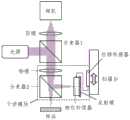
图5示出根据本公开一应用示例的示意图,如图5所示,本公开实施例提出了一种待测表面形貌测量方法,这一测量方法可以实现对待测表面的高度测量,图6示出了利用该测量方法的一种采用非机械扫描的基于扫描脉冲时间间隔的相干扫描干涉仪的示意图。Figure 5 shows a schematic diagram of an application example according to the present disclosure. As shown in Figure 5, an embodiment of the present disclosure proposes a method for measuring the morphology of a surface to be measured. This measurement method can achieve height measurement of the surface to be measured. Figure 6 shows a schematic diagram of a coherent scanning interferometer based on a scanning pulse time interval and adopting non-mechanical scanning using the measurement method.
如图7所示,该待测表面形貌测量过程可以大致分为四个步骤:As shown in FIG7 , the process of measuring the surface topography to be measured can be roughly divided into four steps:
步骤一、光源分束。具体的,该光源是一个时间间隔可调的激光发射器,发出的脉冲光被偏振分束器1分为正交偏振的两路:一路通过一段长光纤进行延迟,再经声光移频器1移频后进入偏振合束器;另一路直接进入声光移频器2移频,并进入偏振合束器,此时,合束后的光在不同偏振态上有着不同的时延和光频。偏振合束器输出的光被光纤准直器耦合到空间中,这一对正交偏振光在偏振分束器2处再次被分离:透射光作为参考臂,经四分之一波片1后照明反射镜;反射光作为测量臂,经四分之一波片2后照明样品的待测点。其中,长光纤的作用是:使干涉模块的两干涉臂之间的光程差是光程间隔的M倍附近(M是正整数)。
步骤二、脉冲时间间隔扫描。具体的,基于对激光发射器重复频率的精确控制,实现对空间间隔的线性扫描。在线性扫描的同时,给声光移频器1和声光移频器2分别加载一对具有微小区别的调制频率,使干涉仪的两干涉臂产生固定的外差频率。在空间间隔线性扫描下,干涉信号的载波相位是均匀变化的,而声光移频器引入的外差频率被时间积分后也表现为均匀变化的相位。声光移频器1和声光移频器2共同组成了一个动态的相位补偿器,通过调节外差频率与线性扫描速度相匹配,可以实现对干涉信号条纹频率的相位补偿。
步骤三、光源合束。具体的,反射镜和样品的反射光再次分别经过四分之一波片1和四分之一波片2后进入偏振分束器2,由于经过两次四分之一波片会将偏振态旋转90度,因此,它们分别以反射和透射的形式经过偏振分束器2并合光。成像镜组将样品的待测点表面成像至相机像面上,从偏振分束器2输出的合束光经成像镜组后,被偏振片检偏,使得两干涉臂得以干涉,并被相机记录。Step 3: Light source beam combination. Specifically, the reflected light from the reflector and the sample passes through the
步骤四、高度测量。具体的,根据相机采集到的条纹频率经相位补偿后的干涉信号,当扫描激光发射器的重复频率时,若光程差恰好等于M倍的空间间隔,干涉臂一臂的每个脉冲都会和它之后的第M个脉冲发生干涉,根据此时的重复频率便能确定该像素对应点的高度,进而重构全场表面形貌。Step 4: Height measurement. Specifically, based on the interference signal of the fringe frequency collected by the camera after phase compensation, when the repetition frequency of the scanning laser transmitter is used, if the optical path difference is exactly equal to M times the spatial interval, each pulse of one arm of the interference arm will interfere with the Mth pulse after it. Based on the repetition frequency at this time, the height of the corresponding point of the pixel can be determined, and then the full-field surface morphology can be reconstructed.
在本公开实施例中,通过调整测量光和参考光之间的光程差,以进行相干扫描,同时对光源发出的光分束得到的测量光和/或参考光进行相位补偿,并根据扫描过程中采集的干涉图像序列,确定待测表面的高度分布。该过程利用相位补偿的方法,降低了测量光和参考光合束后、形成的时间相移干涉条纹密度,能够在保持测量精度的同时,减少了干涉信号细节,提高了扫描速度,进而降低了环境扰动对测量结果的影响,提升了待测表面形貌测量过程的鲁棒性。In the disclosed embodiment, the optical path difference between the measuring light and the reference light is adjusted to perform coherent scanning, and phase compensation is performed on the measuring light and/or the reference light obtained by splitting the light beam emitted by the light source, and the height distribution of the surface to be measured is determined according to the interference image sequence collected during the scanning process. This process uses the phase compensation method to reduce the density of the time phase-shifted interference fringes formed after the measuring light and the reference light are combined, which can reduce the interference signal details while maintaining the measurement accuracy, increase the scanning speed, and thus reduce the impact of environmental disturbances on the measurement results, and improve the robustness of the surface morphology measurement process to be measured.
需要说明的是,以上实施例的描述顺序不作为对本申请实施例优选顺序的限定。It should be noted that the description order of the above embodiments is not intended to limit the preferred order of the embodiments of the present application.
另外需要说明的是,本公开实施例的待测表面形貌测量方法可以用于迈克尔逊型、Mirau型等干涉光路的类型中,还可以应用于其他任意的干涉光路的类型,本公开对此不作限定。It should also be noted that the surface morphology measurement method of the embodiment of the present disclosure can be used in interference light paths such as the Michelson type and the Mirau type, and can also be applied to any other type of interference light paths, which is not limited by the present disclosure.
本公开实施例的待测表面形貌测量方法也不限于上述机械方式和非机械方式的相位补偿,还可以应用其他任意形式的相位补偿方式,本公开对此也不做限定。The surface morphology measurement method of the embodiment of the present disclosure is not limited to the above-mentioned mechanical and non-mechanical phase compensation methods, and any other form of phase compensation method can also be applied, and the present disclosure does not limit this.
可以理解,本公开提及的上述各个方法实施例,在不违背原理逻辑的情况下,均可以彼此相互结合形成结合后的实施例,限于篇幅,本公开不再赘述。本领域技术人员可以理解,在具体实施方式的上述方法中,各步骤的具体执行顺序应当以其功能和可能的内在逻辑确定。It can be understood that the above-mentioned various method embodiments mentioned in the present disclosure can be combined with each other to form a combined embodiment without violating the principle logic. Due to space limitations, the present disclosure will not repeat them. It can be understood by those skilled in the art that in the above-mentioned method of the specific implementation method, the specific execution order of each step should be determined according to its function and possible internal logic.
此外,本公开还提供了待测表面形貌测量装置、电子设备、计算机可读存储介质、程序,上述均可用来实现本公开提供的任一种待测表面形貌测量方法,相应技术方案和描述和参见方法部分的相应记载,不再赘述。In addition, the present disclosure also provides a device for measuring the surface morphology to be measured, an electronic device, a computer-readable storage medium, and a program, all of which can be used to implement any method for measuring the surface morphology to be measured provided by the present disclosure. The corresponding technical solutions and descriptions are referred to the corresponding records in the method part and will not be repeated here.
图7示出根据本公开实施例的待测表面形貌测量装置的框图。该待测表面形貌测量装置可以为终端设备、服务器或者其他处理设备等。其中,终端设备可以为用户设备(User Equipment,UE)、移动设备、用户终端、终端、蜂窝电话、无绳电话、个人数字处理(Personal Digital Assistant,PDA)、手持设备、计算设备、车载设备、可穿戴设备等。FIG7 shows a block diagram of a device for measuring the topography of a surface to be measured according to an embodiment of the present disclosure. The device for measuring the topography of a surface to be measured may be a terminal device, a server or other processing device, etc. The terminal device may be a user equipment (UE), a mobile device, a user terminal, a terminal, a cellular phone, a cordless phone, a personal digital assistant (PDA), a handheld device, a computing device, a vehicle-mounted device, a wearable device, etc.
在一些可能的实现方式中,该待测表面形貌测量装置可以通过处理器调用存储器中存储的计算机可读指令的方式来实现。In some possible implementations, the device for measuring the surface topography to be measured may be implemented by a processor calling computer-readable instructions stored in a memory.
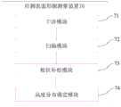
如图7所示,所述待测表面形貌测量装置70可以包括:As shown in FIG. 7 , the device 70 for measuring the surface topography to be measured may include:
一种待测表面形貌测量装置,包括:A device for measuring the topography of a surface to be measured, comprising:
干涉模块71,用于将光源发出的光束进行分束,形成测量光和参考光,所述测量光到达待测表面、并被所述待测表面反射,所述参考光到达反射镜表面、并被所述反射镜表面反射,被反射的所述测量光和被反射的所述参考光合束后、产生干涉图像;The
扫描模块72,用于调整所述测量光和所述参考光之间的相对光程差,使所述相对光程差在预设扫描范围内变化;A
相位补偿模块73,用于对所述测量光和/或所述参考光进行相位补偿,以降低所述干涉图像中时间相移干涉条纹的密度;A
高度分布确定模块74,用于根据所述相对光程差在预设扫描范围内变化时采集的干涉图像序列,确定所述待测表面的高度分布。The height
在一种可能的实现方式中,在一种可能的实现方式中,所述光源为低相干光,所述相位补偿模块,用于:In a possible implementation, in a possible implementation, the light source is low-coherence light, and the phase compensation module is used to:
对所述测量光输出补偿相位,以对所述测量光进行相位补偿;Outputting a phase compensation for the measurement light to perform phase compensation on the measurement light;
和/或and/or
对所述参考光输出补偿相位,以对所述参考光进行相位补偿。A phase compensation is outputted for the reference light to perform phase compensation on the reference light.
在一种可能的实现方式中,所述扫描模块,用于:In a possible implementation, the scanning module is used to:
调整所述测量光通过的测量臂和/或所述参考光通过的参考臂的长度,以调整所述相对光程差。The length of the measuring arm through which the measuring light passes and/or the length of the reference arm through which the reference light passes is adjusted to adjust the relative optical path difference.
在一种可能的实现方式中,在调整所述光程差时,所述补偿相位与所述长度的变化量成正比。In a possible implementation, when adjusting the optical path difference, the compensation phase is proportional to the change in the length.
在一种可能的实现方式中,所述光源为脉冲激光器,所述干涉模块,用于:In a possible implementation, the light source is a pulsed laser, and the interference module is used to:
控制所述脉冲激光器每间隔预设时间间隔发出一个激光脉冲;Controlling the pulse laser to emit a laser pulse at a preset time interval;
将所述激光脉冲进行分束,形成测量光和参考光;Splitting the laser pulse to form a measuring light and a reference light;
所述扫描模块,用于:The scanning module is used for:
根据所述时间间隔,在同一激光脉冲分束形成的测量光和所述参考光之间设置初始光程差,使每个脉冲的测量光与每个脉冲之后的第M个脉冲的参考光之间发生干涉,M为正整数;According to the time interval, an initial optical path difference is set between the measurement light formed by the same laser pulse splitting and the reference light, so that interference occurs between the measurement light of each pulse and the reference light of the Mth pulse after each pulse, where M is a positive integer;
调整所述时间间隔,使所述相对光程差在预设扫描范围内变化。The time interval is adjusted so that the relative optical path difference changes within a preset scanning range.
在一种可能的实现方式中,所述相位补偿模块,用于:In a possible implementation, the phase compensation module is used to:
对所述测量光和所述参考光加载不同的调制相位。Different modulation phases are applied to the measuring light and the reference light.
在一种可能的实现方式中,所述干涉模块,用于:In a possible implementation, the interference module is used to:
将光源发出的光束进行偏振分束,形成测量光和参考光;The light beam emitted by the light source is polarized and split to form measurement light and reference light;
所述被反射的所述测量光和被反射的所述参考光合束后、产生干涉图像,包括:The reflected measurement light and the reflected reference light are combined to generate an interference image, comprising:
被反射的所述测量光和被反射的所述参考光被检偏后、产生干涉图像。The reflected measuring light and the reflected reference light are polarized to generate an interference image.
本公开实施例还提出一种计算机可读存储介质,其上存储有计算机程序指令,所述计算机程序指令被处理器执行时实现上述方法。计算机可读存储介质可以是非易失性计算机可读存储介质。The embodiment of the present disclosure also provides a computer-readable storage medium, on which computer program instructions are stored, and when the computer program instructions are executed by a processor, the above method is implemented. The computer-readable storage medium may be a non-volatile computer-readable storage medium.
本公开实施例还提出一种电子设备,包括:处理器;用于存储处理器可执行指令的存储器;其中,所述处理器被配置为调用所述存储器存储的指令,以执行上述方法。An embodiment of the present disclosure further proposes an electronic device, comprising: a processor; and a memory for storing instructions executable by the processor; wherein the processor is configured to call the instructions stored in the memory to execute the above method.
本公开实施例还提供了一种计算机程序产品,包括计算机可读代码,当计算机可读代码在设备上运行时,设备中的处理器执行用于实现如上任一实施例提供的待测表面形貌测量的指令。The embodiments of the present disclosure also provide a computer program product, including computer-readable codes. When the computer-readable codes are executed on a device, a processor in the device executes instructions for implementing the measurement of the surface morphology to be measured provided in any of the above embodiments.
本公开实施例还提供了另一种计算机程序产品,用于存储计算机可读指令,指令被执行时使得计算机执行上述任一实施例提供的待测表面形貌测量的操作。The embodiments of the present disclosure also provide another computer program product for storing computer-readable instructions, which, when executed, enable a computer to perform the operations of measuring the surface topography to be measured provided by any of the above embodiments.
电子设备可以被提供为终端、服务器或其它形态的设备。The electronic device may be provided as a terminal, a server, or a device in other forms.
图8示出根据本公开实施例的一种电子设备1900的框图。例如,电子设备1900可以被提供为一服务器。参照图8,电子设备1900包括处理组件1922,其进一步包括一个或多个处理器,以及由存储器1932所代表的存储器资源,用于存储可由处理组件1922的执行的指令,例如应用程序。存储器1932中存储的应用程序可以包括一个或一个以上的每一个对应于一组指令的模块。此外,处理组件1922被配置为执行指令,以执行上述方法。FIG8 shows a block diagram of an
电子设备1900还可以包括一个电源组件1926被配置为执行电子设备1900的电源管理,一个有线或无线网络接口1950被配置为将电子设备1900连接到网络,和一个输入输出接口1958。电子设备1900可以操作基于存储在存储器1932的操作系统,例如WindowsServerTM,Mac OS XTM,UnixTM,LinuxTM,FreeBSDTM或类似。The
在示例性实施例中,还提供了一种非易失性计算机可读存储介质,例如包括计算机程序指令的存储器1932,上述计算机程序指令可由电子设备1900的处理组件1922执行以完成上述方法。In an exemplary embodiment, a non-volatile computer-readable storage medium is also provided, such as a
本公开可以是系统、方法和/或计算机程序产品。计算机程序产品可以包括计算机可读存储介质,其上载有用于使处理器实现本公开的各个方面的计算机可读程序指令。The present disclosure may be a system, a method and/or a computer program product. The computer program product may include a computer-readable storage medium carrying computer-readable program instructions for causing a processor to implement various aspects of the present disclosure.
计算机可读存储介质可以是可以保持和存储由指令执行设备使用的指令的有形设备。计算机可读存储介质例如可以是――但不限于――电存储设备、磁存储设备、光存储设备、电磁存储设备、半导体存储设备或者上述的任意合适的组合。计算机可读存储介质的更具体的例子(非穷举的列表)包括:便携式计算机盘、硬盘、随机存取存储器(RAM)、只读存储器(ROM)、可擦式可编程只读存储器(EPROM或闪存)、静态随机存取存储器(SRAM)、便携式压缩盘只读存储器(CD-ROM)、数字多功能盘(DVD)、记忆棒、软盘、机械编码设备、例如其上存储有指令的打孔卡或凹槽内凸起结构、以及上述的任意合适的组合。这里所使用的计算机可读存储介质不被解释为瞬时信号本身,诸如无线电波或者其他自由传播的电磁波、通过波导或其他传输媒介传播的电磁波(例如,通过光纤电缆的光脉冲)、或者通过电线传输的电信号。A computer-readable storage medium may be a tangible device that can hold and store instructions used by an instruction execution device. A computer-readable storage medium may be, for example, but not limited to, an electrical storage device, a magnetic storage device, an optical storage device, an electromagnetic storage device, a semiconductor storage device, or any suitable combination of the above. More specific examples of computer-readable storage media (a non-exhaustive list) include: a portable computer disk, a hard disk, a random access memory (RAM), a read-only memory (ROM), an erasable programmable read-only memory (EPROM or flash memory), a static random access memory (SRAM), a portable compact disk read-only memory (CD-ROM), a digital versatile disk (DVD), a memory stick, a floppy disk, a mechanical encoding device, such as a punch card or a raised structure in a groove on which instructions are stored, and any suitable combination of the above. As used herein, a computer-readable storage medium is not to be interpreted as a transient signal per se, such as a radio wave or other freely propagating electromagnetic wave, an electromagnetic wave propagating through a waveguide or other transmission medium (e.g., a light pulse through a fiber optic cable), or an electrical signal transmitted through a wire.
这里所描述的计算机可读程序指令可以从计算机可读存储介质下载到各个计算/处理设备,或者通过网络、例如因特网、局域网、广域网和/或无线网下载到外部计算机或外部存储设备。网络可以包括铜传输电缆、光纤传输、无线传输、路由器、防火墙、交换机、网关计算机和/或边缘服务器。每个计算/处理设备中的网络适配卡或者网络接口从网络接收计算机可读程序指令,并转发该计算机可读程序指令,以供存储在各个计算/处理设备中的计算机可读存储介质中。The computer-readable program instructions described herein can be downloaded from a computer-readable storage medium to each computing/processing device, or downloaded to an external computer or external storage device via a network, such as the Internet, a local area network, a wide area network, and/or a wireless network. The network can include copper transmission cables, optical fiber transmissions, wireless transmissions, routers, firewalls, switches, gateway computers, and/or edge servers. The network adapter card or network interface in each computing/processing device receives the computer-readable program instructions from the network and forwards the computer-readable program instructions for storage in the computer-readable storage medium in each computing/processing device.
用于执行本公开操作的计算机程序指令可以是汇编指令、指令集架构(ISA)指令、机器指令、机器相关指令、微代码、固件指令、状态设置数据、或者以一种或多种编程语言的任意组合编写的源代码或目标代码,所述编程语言包括面向对象的编程语言—诸如Smalltalk、C++、python、Java等,以及常规的过程式编程语言—诸如“C”语言或类似的编程语言。计算机可读程序指令可以完全地在用户计算机上执行、部分地在用户计算机上执行、作为一个独立的软件包执行、部分在用户计算机上部分在远程计算机上执行、或者完全在远程计算机或服务器上执行。在涉及远程计算机的情形中,远程计算机可以通过任意种类的网络—包括局域网(LAN)或广域网(WAN)—连接到用户计算机,或者,可以连接到外部计算机(例如利用因特网服务提供商来通过因特网连接)。在一些实施例中,通过利用计算机可读程序指令的状态信息来个性化定制电子电路,例如可编程逻辑电路、现场可编程门阵列(FPGA)或可编程逻辑阵列(PLA),该电子电路可以执行计算机可读程序指令,从而实现本公开的各个方面。The computer program instructions for performing the operation of the present disclosure may be assembly instructions, instruction set architecture (ISA) instructions, machine instructions, machine-related instructions, microcode, firmware instructions, state setting data, or source code or object code written in any combination of one or more programming languages, including object-oriented programming languages, such as Smalltalk, C++, python, Java, etc., and conventional procedural programming languages, such as "C" language or similar programming languages. Computer-readable program instructions may be executed completely on a user's computer, partially on a user's computer, as an independent software package, partially on a user's computer, partially on a remote computer, or completely on a remote computer or server. In the case of a remote computer, the remote computer may be connected to the user's computer via any type of network, including a local area network (LAN) or a wide area network (WAN), or may be connected to an external computer (e.g., using an Internet service provider to connect via the Internet). In some embodiments, an electronic circuit, such as a programmable logic circuit, a field programmable gate array (FPGA), or a programmable logic array (PLA), may be customized by utilizing the state information of the computer-readable program instructions, and the electronic circuit may execute the computer-readable program instructions, thereby realizing various aspects of the present disclosure.
这里参照根据本公开实施例的方法、装置(系统)和计算机程序产品的流程图和/或框图描述了本公开的各个方面。应当理解,流程图和/或框图的每个方框以及流程图和/或框图中各方框的组合,都可以由计算机可读程序指令实现。Various aspects of the present disclosure are described herein with reference to the flowcharts and/or block diagrams of the methods, devices (systems) and computer program products according to the embodiments of the present disclosure. It should be understood that each box in the flowchart and/or block diagram and the combination of each box in the flowchart and/or block diagram can be implemented by computer-readable program instructions.
这些计算机可读程序指令可以提供给通用计算机、专用计算机或其它可编程数据处理装置的处理器,从而生产出一种机器,使得这些指令在通过计算机或其它可编程数据处理装置的处理器执行时,产生了实现流程图和/或框图中的一个或多个方框中规定的功能/动作的装置。也可以把这些计算机可读程序指令存储在计算机可读存储介质中,这些指令使得计算机、可编程数据处理装置和/或其他设备以特定方式工作,从而,存储有指令的计算机可读介质则包括一个制造品,其包括实现流程图和/或框图中的一个或多个方框中规定的功能/动作的各个方面的指令。These computer-readable program instructions can be provided to a processor of a general-purpose computer, a special-purpose computer, or other programmable data processing device, thereby producing a machine, so that when these instructions are executed by the processor of the computer or other programmable data processing device, a device that implements the functions/actions specified in one or more boxes in the flowchart and/or block diagram is generated. These computer-readable program instructions can also be stored in a computer-readable storage medium, and these instructions cause the computer, programmable data processing device, and/or other equipment to work in a specific manner, so that the computer-readable medium storing the instructions includes a manufactured product, which includes instructions for implementing various aspects of the functions/actions specified in one or more boxes in the flowchart and/or block diagram.
也可以把计算机可读程序指令加载到计算机、其它可编程数据处理装置、或其它设备上,使得在计算机、其它可编程数据处理装置或其它设备上执行一系列操作步骤,以产生计算机实现的过程,从而使得在计算机、其它可编程数据处理装置、或其它设备上执行的指令实现流程图和/或框图中的一个或多个方框中规定的功能/动作。Computer-readable program instructions may also be loaded onto a computer, other programmable data processing apparatus, or other device so that a series of operating steps are performed on the computer, other programmable data processing apparatus, or other device to produce a computer-implemented process, thereby causing the instructions executed on the computer, other programmable data processing apparatus, or other device to implement the functions/actions specified in one or more boxes in the flowchart and/or block diagram.
附图中的流程图和框图显示了根据本公开的多个实施例的系统、方法和计算机程序产品的可能实现的体系架构、功能和操作。在这点上,流程图或框图中的每个方框可以代表一个模块、程序段或指令的一部分,所述模块、程序段或指令的一部分包含一个或多个用于实现规定的逻辑功能的可执行指令。在有些作为替换的实现中,方框中所标注的功能也可以以不同于附图中所标注的顺序发生。例如,两个连续的方框实际上可以基本并行地执行,它们有时也可以按相反的顺序执行,这依所涉及的功能而定。也要注意的是,框图和/或流程图中的每个方框、以及框图和/或流程图中的方框的组合,可以用执行规定的功能或动作的专用的基于硬件的系统来实现,或者可以用专用硬件与计算机指令的组合来实现。The flow chart and block diagram in the accompanying drawings show the possible architecture, function and operation of the system, method and computer program product according to multiple embodiments of the present disclosure. In this regard, each square box in the flow chart or block diagram can represent a part of a module, program segment or instruction, and the part of the module, program segment or instruction contains one or more executable instructions for realizing the specified logical function. In some alternative implementations, the function marked in the square box can also occur in a sequence different from that marked in the accompanying drawings. For example, two continuous square boxes can actually be executed substantially in parallel, and they can sometimes be executed in the opposite order, depending on the functions involved. It should also be noted that each square box in the block diagram and/or flow chart, and the combination of the square boxes in the block diagram and/or flow chart can be implemented with a dedicated hardware-based system that performs the specified function or action, or can be implemented with a combination of special hardware and computer instructions.
该计算机程序产品可以具体通过硬件、软件或其结合的方式实现。在一个可选实施例中,所述计算机程序产品具体体现为计算机存储介质,在另一个可选实施例中,计算机程序产品具体体现为软件产品,例如软件开发包(Software Development Kit,SDK)等等。The computer program product may be implemented in hardware, software or a combination thereof. In one optional embodiment, the computer program product is embodied as a computer storage medium, and in another optional embodiment, the computer program product is embodied as a software product, such as a software development kit (SDK) and the like.
以上已经描述了本公开的各实施例,上述说明是示例性的,并非穷尽性的,并且也不限于所披露的各实施例。在不偏离所说明的各实施例的范围和精神的情况下,对于本技术领域的普通技术人员来说许多修改和变更都是显而易见的。本文中所用术语的选择,旨在最好地解释各实施例的原理、实际应用或对市场中的技术的改进,或者使本技术领域的其它普通技术人员能理解本文披露的各实施例。The embodiments of the present disclosure have been described above, and the above description is exemplary, not exhaustive, and is not limited to the disclosed embodiments. Many modifications and changes will be apparent to those of ordinary skill in the art without departing from the scope and spirit of the described embodiments. The selection of terms used herein is intended to best explain the principles of the embodiments, practical applications, or improvements to the technology in the market, or to enable other persons of ordinary skill in the art to understand the embodiments disclosed herein.
Claims (10)
Priority Applications (1)
| Application Number | Priority Date | Filing Date | Title |
|---|---|---|---|
| CN202211714393.3ACN115930830A (en) | 2022-12-27 | 2022-12-27 | Method and device for measuring surface morphology to be measured, electronic equipment and storage medium |
Applications Claiming Priority (1)
| Application Number | Priority Date | Filing Date | Title |
|---|---|---|---|
| CN202211714393.3ACN115930830A (en) | 2022-12-27 | 2022-12-27 | Method and device for measuring surface morphology to be measured, electronic equipment and storage medium |
Publications (1)
| Publication Number | Publication Date |
|---|---|
| CN115930830Atrue CN115930830A (en) | 2023-04-07 |
Family
ID=86552281
Family Applications (1)
| Application Number | Title | Priority Date | Filing Date |
|---|---|---|---|
| CN202211714393.3APendingCN115930830A (en) | 2022-12-27 | 2022-12-27 | Method and device for measuring surface morphology to be measured, electronic equipment and storage medium |
Country Status (1)
| Country | Link |
|---|---|
| CN (1) | CN115930830A (en) |
Cited By (3)
| Publication number | Priority date | Publication date | Assignee | Title |
|---|---|---|---|---|
| CN119574384A (en)* | 2024-12-16 | 2025-03-07 | 浙江大学 | Real-time measurement method of 3D dynamic contact angle in gap flow field based on interferometry |
| US12270982B1 (en) | 2023-11-06 | 2025-04-08 | Huazhong University Of Science And Technology | Method, device and computer-readable storage medium for obtaining complex refractive index distribution profile of film |
| WO2025097482A1 (en)* | 2023-11-06 | 2025-05-15 | 华中科技大学 | Method for acquiring complex refractive index distribution morphology of film, and device |
Citations (5)
| Publication number | Priority date | Publication date | Assignee | Title |
|---|---|---|---|---|
| JP2005241348A (en)* | 2004-02-25 | 2005-09-08 | Matsushita Electric Ind Co Ltd | Sound field visualization measuring device |
| CN102057269A (en)* | 2008-11-26 | 2011-05-11 | 齐戈股份有限公司 | Scan error correction in low coherence scanning interferometry |
| CN105606338A (en)* | 2016-01-19 | 2016-05-25 | 北京航空航天大学 | Central wavelength error compensation method based on white light interference testing system |
| CN106017349A (en)* | 2016-06-08 | 2016-10-12 | 中国计量大学 | White light interferometry-based test system and test method therefor |
| CN115096857A (en)* | 2022-06-10 | 2022-09-23 | 北京石油化工学院 | A kind of OCT imaging method and device based on Airy light sheet line scanning |
- 2022
- 2022-12-27CNCN202211714393.3Apatent/CN115930830A/enactivePending
Patent Citations (5)
| Publication number | Priority date | Publication date | Assignee | Title |
|---|---|---|---|---|
| JP2005241348A (en)* | 2004-02-25 | 2005-09-08 | Matsushita Electric Ind Co Ltd | Sound field visualization measuring device |
| CN102057269A (en)* | 2008-11-26 | 2011-05-11 | 齐戈股份有限公司 | Scan error correction in low coherence scanning interferometry |
| CN105606338A (en)* | 2016-01-19 | 2016-05-25 | 北京航空航天大学 | Central wavelength error compensation method based on white light interference testing system |
| CN106017349A (en)* | 2016-06-08 | 2016-10-12 | 中国计量大学 | White light interferometry-based test system and test method therefor |
| CN115096857A (en)* | 2022-06-10 | 2022-09-23 | 北京石油化工学院 | A kind of OCT imaging method and device based on Airy light sheet line scanning |
Non-Patent Citations (3)
| Title |
|---|
| 李华煜, 徐朝仪, 束继祖, 胡金铭: "全息移相干涉技术显示低密度流场的能力", 力学学报, no. 02, 19 March 1979 (1979-03-19), pages 171 - 178* |
| 毕泽坤等: "基于两步广义相移干涉术的微纳形变测量", 光学技术, vol. 44, no. 2, 31 March 2018 (2018-03-31), pages 252 - 256* |
| 赵伟瑞, 曹根瑞: "斩波式自适应移相干涉技术", 光学学报, no. 07, 17 July 2002 (2002-07-17)* |
Cited By (4)
| Publication number | Priority date | Publication date | Assignee | Title |
|---|---|---|---|---|
| US12270982B1 (en) | 2023-11-06 | 2025-04-08 | Huazhong University Of Science And Technology | Method, device and computer-readable storage medium for obtaining complex refractive index distribution profile of film |
| WO2025097482A1 (en)* | 2023-11-06 | 2025-05-15 | 华中科技大学 | Method for acquiring complex refractive index distribution morphology of film, and device |
| CN119574384A (en)* | 2024-12-16 | 2025-03-07 | 浙江大学 | Real-time measurement method of 3D dynamic contact angle in gap flow field based on interferometry |
| CN119574384B (en)* | 2024-12-16 | 2025-05-30 | 浙江大学 | Real-time measurement method for 3D dynamic contact angle in slit flow field based on interferometry |
Similar Documents
| Publication | Publication Date | Title |
|---|---|---|
| CN115930830A (en) | Method and device for measuring surface morphology to be measured, electronic equipment and storage medium | |
| JP5241806B2 (en) | Apparatus and method for surface contour measurement | |
| CN104748835B (en) | Amount of interference detaches laser interference vialog nonlinearity erron modification method and device | |
| CN103727891B (en) | Synchronize three-dimensional speckle interferometer measuration system and measuring method | |
| CN106768280B (en) | A vibration detection device based on multi-wavelength lensless Fourier transform digital holography | |
| KR101544962B1 (en) | Transmission-type Interference Apparatus using Optical Fibers for Measuring Geometrical Thickness and Refractive index | |
| CN109000781B (en) | Device and method for measuring structural micro-vibration line domain | |
| CN109539975A (en) | Single frequency laser interferometer nonlinearity erron modification method and device | |
| CN103712569B (en) | Based on single image fast phase shift system and the method for detecting phases of deflection angle | |
| CN219390835U (en) | Detection device | |
| JP2018077140A (en) | Phase shift interferometer | |
| KR20150116332A (en) | Reflection-type Interference Apparatus using Optical Fibers for Measuring Geometrical Thickness and Refractive index | |
| CN115112045B (en) | Interferometric measurement method based on all-fiber orthogonal polarization optical path matching short coherent light source | |
| CN112729135A (en) | Area array frequency sweep distance measuring/thickness measuring device and method with active optical anti-shake function | |
| CN110319939A (en) | Polarize the short-coherence light source system and experimental method of phase shift combination PZT phase shift | |
| US11892292B2 (en) | Methods and systems of holographic interferometry | |
| CN105300276B (en) | A kind of dual wavelength list exposure interferometric method and system | |
| CN115566522B (en) | Laser coherent synthesis phase error compensation device and method | |
| CN110160624B (en) | Optical fiber point diffraction device for three-dimensional vibration measurement and measurement method | |
| CN115598147A (en) | Microsphere internal and external surface defect detection device and method based on white light micro-interference | |
| JP2018525635A (en) | Method and apparatus for deriving the topography of a test surface | |
| US20110299090A1 (en) | Real-time interferometer | |
| CN110926360A (en) | A device for measuring free-form surfaces with full-field heterodyne phase-shifting | |
| KR102598511B1 (en) | Ultrafast camera system and measurement method thereof | |
| CN112731345B (en) | Device and method for anti-vibration area array frequency sweep ranging/thickness measurement with active optical anti-shake function |
Legal Events
| Date | Code | Title | Description |
|---|---|---|---|
| PB01 | Publication | ||
| PB01 | Publication | ||
| SE01 | Entry into force of request for substantive examination | ||
| SE01 | Entry into force of request for substantive examination |