CN115928693A - Rigid landfill - Google Patents
Rigid landfillDownload PDFInfo
- Publication number
- CN115928693A CN115928693ACN202211593638.1ACN202211593638ACN115928693ACN 115928693 ACN115928693 ACN 115928693ACN 202211593638 ACN202211593638 ACN 202211593638ACN 115928693 ACN115928693 ACN 115928693A
- Authority
- CN
- China
- Prior art keywords
- landfill
- walls
- bottom plate
- cell
- rigid
- Prior art date
- Legal status (The legal status is an assumption and is not a legal conclusion. Google has not performed a legal analysis and makes no representation as to the accuracy of the status listed.)
- Pending
Links
Images

Classifications
- Y—GENERAL TAGGING OF NEW TECHNOLOGICAL DEVELOPMENTS; GENERAL TAGGING OF CROSS-SECTIONAL TECHNOLOGIES SPANNING OVER SEVERAL SECTIONS OF THE IPC; TECHNICAL SUBJECTS COVERED BY FORMER USPC CROSS-REFERENCE ART COLLECTIONS [XRACs] AND DIGESTS
- Y02—TECHNOLOGIES OR APPLICATIONS FOR MITIGATION OR ADAPTATION AGAINST CLIMATE CHANGE
- Y02W—CLIMATE CHANGE MITIGATION TECHNOLOGIES RELATED TO WASTEWATER TREATMENT OR WASTE MANAGEMENT
- Y02W30/00—Technologies for solid waste management
- Y02W30/30—Landfill technologies aiming to mitigate methane emissions
Landscapes
- Processing Of Solid Wastes (AREA)
Abstract
Translated fromChinese
Description
Translated fromChinese技术领域technical field
本发明涉及填埋场技术领域,尤其涉及一种刚性填埋场。The invention relates to the technical field of landfills, in particular to a rigid landfill.
背景技术Background technique
随着城市规模的不断扩大,工业迅速发展,人口不断增长,各种危险废物产生量迅速增长。面对当前越来越严峻的环境保护形势,填埋无疑在危险废物处理中占据举足轻重的位置,在国内政策支持下,填埋必将在此后很长一段时间内据主导地位。With the continuous expansion of city scale, rapid industrial development and population growth, the production of various hazardous wastes is increasing rapidly. Faced with the current increasingly severe environmental protection situation, landfill undoubtedly occupies a pivotal position in the treatment of hazardous waste. With the support of domestic policies, landfill will surely occupy a dominant position for a long time to come.
目前,常见的刚性填埋场使用混凝土将填埋场分成多个方形的填埋单元,这种结构的单边池壁受力大,在转角处易产生池壁开裂,结构强度和稳定性较差,同时,在刚性填埋单元的建造中,不仅需要满足填埋的需求,还需要考虑填埋场封场后的承重等,刚性填埋场的填埋单元在设计建造时,就需要完善地考虑其力学稳定性和强度等问题。因此,在刚性填埋场对建造要求高的条件下,现有刚性填埋场的建造成本较高,相应地,危险废物处理的成本亦较高,这种现状限制了刚性填埋场的发展。At present, common rigid landfills use concrete to divide the landfill into multiple square landfill units. The single-sided pool wall of this structure is stressed, and the pool wall is prone to cracking at the corners, and the structural strength and stability are relatively low. At the same time, in the construction of rigid landfill units, it is not only necessary to meet the needs of landfill, but also to consider the load bearing after the landfill is closed. When designing and constructing the landfill units of rigid landfills, it is necessary to improve Consider its mechanical stability and strength and other issues carefully. Therefore, under the condition that rigid landfills have high construction requirements, the construction cost of existing rigid landfills is relatively high, and correspondingly, the cost of hazardous waste treatment is also high. This situation limits the development of rigid landfills .
发明内容Contents of the invention
本发明目的就是为了解决现有填埋场建造成本高、单边池壁受力大、强度和稳定性不高的问题,提供了一种刚性填埋场,不仅可以节约建造成本,提高经济效益,同时减小单边池壁受力,避免转角处池壁开裂,提升整体结构的强度和稳定性。The purpose of the present invention is to solve the problems of high construction cost, large force on one side of the pool wall, low strength and stability of the existing landfill, and provide a rigid landfill, which can not only save construction cost, but also improve economic benefits , while reducing the force on the unilateral pool wall, avoiding the cracking of the pool wall at the corner, and improving the strength and stability of the overall structure.
为了实现上述目的,本发明采用了如下技术方案:In order to achieve the above object, the present invention adopts the following technical solutions:
一种刚性填埋场,包括填埋场本体,填埋场本体内包含一组设于底板上的填埋单元格,每个填埋单元格均为正六边形结构,其包括六面相连的墙壁,墙壁垂直固定在底板上,同一个填埋单元格内相邻两个墙壁之间的夹角为120°;A rigid landfill, including a landfill body. The landfill body contains a group of landfill cells arranged on the bottom plate. Each landfill cell is a regular hexagonal structure, which includes six-sided connected Walls, the walls are vertically fixed on the base plate, and the angle between two adjacent walls in the same landfill cell is 120°;
每个填埋单元格与其相邻的六个填埋单元格分别共用六面墙壁,每个填埋单元格内衬人工防渗衬层,底板和墙壁上均设有防腐涂层,以用于增加填埋单元的使用寿命和结构强度。Each landfill cell shares six walls with its six adjacent landfill cells. Each landfill cell is lined with artificial anti-seepage lining, and anti-corrosion coatings are provided on the floor and walls for Increase the service life and structural strength of the landfill unit.
进一步地,所述墙壁和底板均为钢筋混凝土结构。Further, the walls and the floor are reinforced concrete structures.
进一步地,所述填埋场本体的上方设有相互配合的行车和吊索,且二者沿着填埋单元格的单边墙壁连线设置,以用于吊运废物至填埋单元内。Further, the upper part of the landfill body is provided with cooperating cranes and slings, and the two are arranged along the line of the single wall of the landfill unit for hoisting waste into the landfill unit.
与现有技术相比,本发明的技术方案的优点具体在于:Compared with the prior art, the advantages of the technical solution of the present invention are in particular:
(1)由于池壁转角由90°增加到120°,转角受力条件改善,可有效防止转角处池壁开裂,提高工程施工质量;(1) Since the pool wall corner is increased from 90° to 120°, the force condition of the corner is improved, which can effectively prevent the pool wall from cracking at the corner and improve the construction quality of the project;
(2)等体积等深度的刚埋单元,本发明的刚埋单元的单边池壁长度远小于方形刚埋单元的单边池壁长度,改善了池壁的受力条件,可以减小池壁配筋和池壁厚度,降低投资成本;(2) Just-buried units of equal volume and depth, the length of the single-side pool wall of the just-buried unit of the present invention is much smaller than that of the square just-buried unit, which improves the stress conditions of the pool wall and can reduce the pool wall Reinforcement and pool wall thickness reduce investment costs;
(3)等体积等深度的刚埋单元,本发明的刚埋单元比正方形刚埋单元减少池壁总长度6.6%以上,内侧壁面积减少6.6%以上,可以减少钢筋混凝土施工量和内壁防腐蚀施工面积,降低投资成本;(3) For the just-buried units of equal volume and depth, the just-buried unit of the present invention reduces the total length of the pool wall by more than 6.6% and the area of the inner wall by more than 6.6% compared with the square just-buried unit, which can reduce the construction amount of reinforced concrete and the anti-corrosion of the inner wall Construction area, reduce investment cost;
(4)本发明的刚性填埋单元相比较方形刚埋单元,池壁受力条件极大改善,填埋单元混凝土量减少,增加了填埋单元的有效容积,提高填埋场经济效益;(4) Compared with the square rigid buried unit, the rigid landfill unit of the present invention greatly improves the stress condition of the pool wall, reduces the concrete volume of the landfill unit, increases the effective volume of the landfill unit, and improves the economic benefits of the landfill site;
(5)本发明的刚性填埋场,在不增加投资成本的情况下可增加填埋单元的高度,提高填埋场的土地利用率,延长填埋场的服务年限。(5) The rigid landfill of the present invention can increase the height of the landfill unit without increasing the investment cost, improve the land utilization rate of the landfill, and prolong the service life of the landfill.
附图说明Description of drawings
图1为本发明的刚性填埋场结构示意图;Fig. 1 is rigid landfill structure schematic diagram of the present invention;
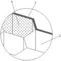
图2为图1的A局部放大图。FIG. 2 is a partial enlarged view of A in FIG. 1 .
具体实施方式Detailed ways
实施例1Example 1
为使本发明更加清楚明白,下面结合附图对本发明的一种刚性填埋场进一步说明,此处所描述的具体实施例仅用于解释本发明,并不用于限定本发明。In order to make the present invention clearer, a rigid landfill of the present invention will be further described below with reference to the accompanying drawings. The specific embodiments described here are only for explaining the present invention, and are not intended to limit the present invention.
参见图1和图2,一种刚性填埋场,包括填埋场本体1,其特征在于:Referring to Fig. 1 and Fig. 2, a kind of rigid landfill, comprises
填埋场本体1内包含一组设于底板1a上的填埋单元格2,每个填埋单元格2均为正六边形结构,其包括六面相连的墙壁2a,墙壁2a垂直固定在底板1a上,墙壁2a和底板1a均为钢筋混凝土结构;The
同一个填埋单元格2内相邻两个墙壁2a之间的夹角为120°;The angle between two
参见图2,每个填埋单元格2与其相邻的六个填埋单元格2分别共用六面墙壁,每个填埋单元格2内衬人工防渗衬层3,底板1a和墙壁2a上均设有防腐涂层4,以用于增加填埋单元的使用寿命和结构强度;Referring to Fig. 2, each
参见图1,填埋场本体1的上方设有相互配合的行车6和吊索5,且二者沿着填埋单元格2的单边池壁连线设置,以用于吊运废物至填埋单元内。Referring to Fig. 1, above the
填埋场建设完毕之后,通过车辆运输需填埋的固体废弃物至填埋场,然后通过转运设备将危险废物填埋,再通过重型机械多次碾压。本发明的正六边形结构可以承受更大的强度,可以增加填埋单元的高度,相应地也增加了填埋场的容量。新旧填埋单元层层相连,充分利用了正六边形结构的稳定性。After the construction of the landfill is completed, the solid waste to be buried is transported to the landfill by vehicles, and then the hazardous waste is landfilled by the transfer equipment, and then crushed by heavy machinery multiple times. The regular hexagonal structure of the invention can bear greater strength, can increase the height of the landfill unit, and correspondingly increases the capacity of the landfill. The old and new landfill units are connected layer by layer, making full use of the stability of the regular hexagonal structure.
除上述实施例外,本发明还可以有其他实施方式。凡采用等同替换或等效变换形成的技术方案,均落在本发明要求的保护范围。In addition to the above-mentioned embodiments, the present invention can also have other implementations. All technical solutions formed by equivalent replacement or equivalent transformation fall within the scope of protection required by the present invention.
Claims (3)
Translated fromChinesePriority Applications (1)
| Application Number | Priority Date | Filing Date | Title |
|---|---|---|---|
| CN202211593638.1ACN115928693A (en) | 2022-12-13 | 2022-12-13 | Rigid landfill |
Applications Claiming Priority (1)
| Application Number | Priority Date | Filing Date | Title |
|---|---|---|---|
| CN202211593638.1ACN115928693A (en) | 2022-12-13 | 2022-12-13 | Rigid landfill |
Publications (1)
| Publication Number | Publication Date |
|---|---|
| CN115928693Atrue CN115928693A (en) | 2023-04-07 |
Family
ID=86650495
Family Applications (1)
| Application Number | Title | Priority Date | Filing Date |
|---|---|---|---|
| CN202211593638.1APendingCN115928693A (en) | 2022-12-13 | 2022-12-13 | Rigid landfill |
Country Status (1)
| Country | Link |
|---|---|
| CN (1) | CN115928693A (en) |
Citations (8)
| Publication number | Priority date | Publication date | Assignee | Title |
|---|---|---|---|---|
| JPH08100544A (en)* | 1994-09-30 | 1996-04-16 | Kajima Corp | Super large underground tank |
| RU49070U1 (en)* | 2004-03-26 | 2005-11-10 | Тютюнников Эдуард Алексеевич | GROUND VERTICAL RESERVOIR |
| KR100602051B1 (en)* | 2006-03-06 | 2006-07-19 | 수도권매립지관리공사 | Landfill site with sprinkling system using runoff from landfill |
| CN103635646A (en)* | 2011-06-27 | 2014-03-12 | 株式会社Ihi | Method for constructing low-temperature tank, and low-temperature tank |
| CN209647185U (en)* | 2018-12-25 | 2019-11-19 | 光大绿色环保管理(深圳)有限公司 | A kind of percolate drainage device for rigid landfill yard |
| CN209686503U (en)* | 2019-01-23 | 2019-11-26 | 嘉兴震华生态科技有限公司 | A kind of buried module pond of prefabricated component combined type |
| RU2747219C1 (en)* | 2020-08-17 | 2021-04-29 | Публичное акционерное общество "ОНХП" | Underground group of oil and oil product storage reservoirs |
| CN218990122U (en)* | 2022-12-13 | 2023-05-09 | 江苏柏环环境科技有限公司 | Rigid landfill |
- 2022
- 2022-12-13CNCN202211593638.1Apatent/CN115928693A/enactivePending
Patent Citations (8)
| Publication number | Priority date | Publication date | Assignee | Title |
|---|---|---|---|---|
| JPH08100544A (en)* | 1994-09-30 | 1996-04-16 | Kajima Corp | Super large underground tank |
| RU49070U1 (en)* | 2004-03-26 | 2005-11-10 | Тютюнников Эдуард Алексеевич | GROUND VERTICAL RESERVOIR |
| KR100602051B1 (en)* | 2006-03-06 | 2006-07-19 | 수도권매립지관리공사 | Landfill site with sprinkling system using runoff from landfill |
| CN103635646A (en)* | 2011-06-27 | 2014-03-12 | 株式会社Ihi | Method for constructing low-temperature tank, and low-temperature tank |
| CN209647185U (en)* | 2018-12-25 | 2019-11-19 | 光大绿色环保管理(深圳)有限公司 | A kind of percolate drainage device for rigid landfill yard |
| CN209686503U (en)* | 2019-01-23 | 2019-11-26 | 嘉兴震华生态科技有限公司 | A kind of buried module pond of prefabricated component combined type |
| RU2747219C1 (en)* | 2020-08-17 | 2021-04-29 | Публичное акционерное общество "ОНХП" | Underground group of oil and oil product storage reservoirs |
| CN218990122U (en)* | 2022-12-13 | 2023-05-09 | 江苏柏环环境科技有限公司 | Rigid landfill |
Similar Documents
| Publication | Publication Date | Title |
|---|---|---|
| CN108589965A (en) | Highly seismic region unreinforced viscous damping wall and its construction method | |
| CN112127383A (en) | Offshore wind power foundation with separated bins in barrel top dense beam barrel and single-column negative pressure barrel | |
| CN218990122U (en) | Rigid landfill | |
| CN110374349A (en) | A kind of impaired armored concrete cylinder underpins processing unit and its application method | |
| CN115928693A (en) | Rigid landfill | |
| CN107654102A (en) | Shale oil gas-solid, liquid phase waste sorting formula environmental protection pond and application method | |
| CN207277342U (en) | Pin-connected panel precast concrete form for architectural engineering foundation platform | |
| CN211545685U (en) | Assembled hoisting point component device of super-huge prefabricated reinforced concrete structure | |
| CN100412234C (en) | A large aluminum electrolytic prebaking tank | |
| CN201660105U (en) | Whole lifting device of superstructure of overload ship | |
| CN218176242U (en) | A prefabricated high performance concrete confined shear wall | |
| CN207061654U (en) | A kind of bridging crane main beam | |
| CN216892492U (en) | Few support can have enough to meet need combination foundation structure | |
| CN207079897U (en) | A kind of elevator combined large steel model operating platform | |
| CN210797306U (en) | A prefabricated pier movable automatic dumping ship | |
| CN216334266U (en) | Anti-settling foundation ring beam for steel plate bin | |
| CN107487710B (en) | Three limb side column bilayer shoulder beam support constructions | |
| CN102134915A (en) | Open steel box used for jacking and filling concrete cushion blocks | |
| CN109695205B (en) | System reinforcing method for steel plate combined continuous beam | |
| CN208502396U (en) | A kind of entirety self-supporting glass reinforced plastic inner cylinder supporting arrangement | |
| CN205777582U (en) | Concrete pier bed-jig for assembling large steel structure | |
| CN218622295U (en) | Novel prefabricated engineering plastic foundation | |
| CN216765992U (en) | Steel formwork capable of being used for turnover of concrete foundation of inspection well base | |
| CN221321032U (en) | Basement flexonics's mixed tower fan foundation | |
| CN219672081U (en) | Interlayer isolation capable of being lifted along with attached lifting scaffold |
Legal Events
| Date | Code | Title | Description |
|---|---|---|---|
| PB01 | Publication | ||
| PB01 | Publication | ||
| SE01 | Entry into force of request for substantive examination | ||
| SE01 | Entry into force of request for substantive examination |