CN115916070A - Magnetic device for alimentary canal separation - Google Patents
Magnetic device for alimentary canal separationDownload PDFInfo
- Publication number
- CN115916070A CN115916070ACN202180028704.8ACN202180028704ACN115916070ACN 115916070 ACN115916070 ACN 115916070ACN 202180028704 ACN202180028704 ACN 202180028704ACN 115916070 ACN115916070 ACN 115916070A
- Authority
- CN
- China
- Prior art keywords
- magnet
- hollow organ
- magnet assembly
- organ
- spacer
- Prior art date
- Legal status (The legal status is an assumption and is not a legal conclusion. Google has not performed a legal analysis and makes no representation as to the accuracy of the status listed.)
- Pending
Links
Images


Classifications
- A—HUMAN NECESSITIES
- A61—MEDICAL OR VETERINARY SCIENCE; HYGIENE
- A61F—FILTERS IMPLANTABLE INTO BLOOD VESSELS; PROSTHESES; DEVICES PROVIDING PATENCY TO, OR PREVENTING COLLAPSING OF, TUBULAR STRUCTURES OF THE BODY, e.g. STENTS; ORTHOPAEDIC, NURSING OR CONTRACEPTIVE DEVICES; FOMENTATION; TREATMENT OR PROTECTION OF EYES OR EARS; BANDAGES, DRESSINGS OR ABSORBENT PADS; FIRST-AID KITS
- A61F5/00—Orthopaedic methods or devices for non-surgical treatment of bones or joints; Nursing devices ; Anti-rape devices
- A61F5/0003—Apparatus for the treatment of obesity; Anti-eating devices
- A61F5/0013—Implantable devices or invasive measures
- A61F5/0083—Reducing the size of the stomach, e.g. gastroplasty
- A61F5/0086—Reducing the size of the stomach, e.g. gastroplasty using clamps, folding means or the like
- A—HUMAN NECESSITIES
- A61—MEDICAL OR VETERINARY SCIENCE; HYGIENE
- A61B—DIAGNOSIS; SURGERY; IDENTIFICATION
- A61B17/00—Surgical instruments, devices or methods
- A61B17/12—Surgical instruments, devices or methods for ligaturing or otherwise compressing tubular parts of the body, e.g. blood vessels or umbilical cord
- A61B17/12009—Implements for ligaturing other than by clamps or clips, e.g. using a loop with a slip knot
- A—HUMAN NECESSITIES
- A61—MEDICAL OR VETERINARY SCIENCE; HYGIENE
- A61B—DIAGNOSIS; SURGERY; IDENTIFICATION
- A61B17/00—Surgical instruments, devices or methods
- A61B17/12—Surgical instruments, devices or methods for ligaturing or otherwise compressing tubular parts of the body, e.g. blood vessels or umbilical cord
- A61B17/122—Clamps or clips, e.g. for the umbilical cord
- A—HUMAN NECESSITIES
- A61—MEDICAL OR VETERINARY SCIENCE; HYGIENE
- A61B—DIAGNOSIS; SURGERY; IDENTIFICATION
- A61B17/00—Surgical instruments, devices or methods
- A61B2017/00831—Material properties
- A61B2017/00876—Material properties magnetic
Landscapes
- Health & Medical Sciences (AREA)
- Surgery (AREA)
- Life Sciences & Earth Sciences (AREA)
- General Health & Medical Sciences (AREA)
- Veterinary Medicine (AREA)
- Vascular Medicine (AREA)
- Nuclear Medicine, Radiotherapy & Molecular Imaging (AREA)
- Engineering & Computer Science (AREA)
- Biomedical Technology (AREA)
- Heart & Thoracic Surgery (AREA)
- Public Health (AREA)
- Animal Behavior & Ethology (AREA)
- Molecular Biology (AREA)
- Medical Informatics (AREA)
- Reproductive Health (AREA)
- Gastroenterology & Hepatology (AREA)
- Child & Adolescent Psychology (AREA)
- Obesity (AREA)
- Nursing (AREA)
- Orthopedic Medicine & Surgery (AREA)
- Prostheses (AREA)
Abstract
Translated fromChinese
Description
Translated fromChinese技术领域technical field
本技术领域一般涉及用于治疗消化道病症的医疗技术。特别地,本技术领域涉及用于分隔消化道的中空器官的医疗技术。The technical field generally relates to medical techniques for treating disorders of the digestive tract. In particular, the technical field relates to medical techniques for dividing the hollow organ of the digestive tract.
背景技术Background technique
肥胖外科手术可用于治疗肥胖症,并且通常旨在限制器官(例如胃)的尺寸,和/或绕过胃和/或肠的一部分。肥胖外科手术的实例可包括空肠-回肠分流术、空肠-结肠分流术、胆胰分流术、胃分流术、Roux-en-Y胃分流术、胃成形术、胃囊带术、竖直带状胃成形术、硅橡胶环胃成形术,以及袖状胃切除术。Bariatric surgery can be used to treat obesity and is usually aimed at restricting the size of an organ, such as the stomach, and/or bypassing a portion of the stomach and/or intestine. Examples of bariatric surgery may include jejuno-ileal shunt, jejuno-colon shunt, biliopancreatic shunt, gastric shunt, Roux-en-Y gastric shunt, gastroplasty, gastric banding, vertical banding Gastroplasty, silicone ring gastroplasty, and sleeve gastrectomy.
然而,这些肥胖外科手术通常需要通过切口、缝合、穿刺和/或钉合来改变消化道,这可能对所改变的器官造成创伤并导致出血。这种肥胖外科手术也会导致感染或其他并发症的风险增加。However, these bariatric surgeries often require alterations to the digestive tract through incisions, stitches, punctures, and/or staples, which can cause trauma to the altered organs and lead to bleeding. Such bariatric surgery can also lead to an increased risk of infection or other complications.
因此,关于肥胖外科手术仍然存在许多挑战。Therefore, many challenges remain regarding obesity surgery.
发明内容Contents of the invention
根据一个方面,提供了一种用于分隔患者的消化道的中空器官的方法,该方法包括以下步骤:According to one aspect, there is provided a method for separating a hollow organ of the alimentary canal of a patient, the method comprising the steps of:
将分隔装置的磁体组件插入到患者的腹腔中,磁体组件包括柔性地串联连接的多个磁体元件;inserting a magnet assembly of the spacer into the abdominal cavity of the patient, the magnet assembly comprising a plurality of magnet elements flexibly connected in series;
将磁体组件围绕中空器官的外表面的至少一部分定位在腔外并且沿着分隔线定位,使得磁体组件的前部和磁体组件的后部彼此面对;positioning the magnet assembly around at least a portion of the outer surface of the hollow organ outside the lumen and along the separation line such that the front of the magnet assembly and the rear of the magnet assembly face each other;
将相对的磁体元件磁性地联接在一起以在其之间压缩中空器官的相对壁;以及magnetically coupling opposing magnet elements together to compress opposing walls of the hollow organ therebetween; and
允许中空器官的相对壁融合在一起,同时磁体元件保持磁性地联接。The opposing walls of the hollow organ are allowed to fuse together while the magnet elements remain magnetically coupled.
在一些实现方式中,分隔装置还包括第一端和第二端,其中磁体组件在第一端和第二端之间延伸。In some implementations, the spacer further includes a first end and a second end, wherein the magnet assembly extends between the first end and the second end.
在一些实现方式中,磁体组件包括第一区域和第二区域,并且将分隔装置的磁体组件插入到患者的腹腔中的步骤包括:首先插入磁体组件的第一区域,随后插入磁体组件的第二区域。In some implementations, the magnet assembly includes a first region and a second region, and inserting the magnet assembly of the spacer into the patient's abdominal cavity includes first inserting the first region of the magnet assembly, followed by inserting the second region of the magnet assembly. area.
在一些实现方式中,将磁体组件围绕中空器官的外表面的至少一部分定位在腔外并且沿着分隔线定位的步骤包括:将磁体组件的第一区域定位为磁体组件的后部,并且将磁体组件的第二区域定位为磁体组件的前部。In some implementations, positioning the magnet assembly extraluminally around at least a portion of the outer surface of the hollow organ and along the separation line includes positioning the first region of the magnet assembly as a rear portion of the magnet assembly, and positioning the magnet assembly The second area of the assembly is positioned as the front of the magnet assembly.
在一些实现方式中,磁体元件中的每一个包括磁体接合侧,并且将相对的磁体元件磁性地联接在一起的步骤包括:将磁体元件的彼此面对的相对的磁体接合侧磁性地联接。In some implementations, each of the magnet elements includes a magnet engaging side, and the step of magnetically coupling the opposing magnet elements together includes magnetically coupling opposing magnet engaging sides of the magnet elements that face each other.
在一些实现方式中,磁体组件的第一区域的磁体元件的磁体接合侧具有第一区域磁极,并且磁体组件的第二区域的磁体元件的磁体接合侧具有不同于第一区域磁极的第二区域磁极。In some implementations, the magnet engaging side of the magnet elements of the first region of the magnet assembly has a first region pole and the magnet engaging side of the magnet element of the second region of the magnet assembly has a second region different from the first region pole magnetic pole.
在一些实现方式中,将相对的磁体元件磁性地联接到一起的步骤包括:将第一区域的磁体元件的磁体接合侧的第一区域磁极与第二区域的磁体元件的磁体接合侧的第二区域磁极磁性地联接。In some implementations, the step of magnetically coupling opposing magnet elements together includes coupling a first region pole of a magnet-engaging side of a magnet element of a first region with a second pole of a magnet-engaging side of a magnet element of a second region. The field poles are magnetically coupled.
在一些实现方式中,允许中空器官的相对壁融合在一起,同时将磁体元件保持磁性联接的步骤包括:使磁体组件沿着分隔线保留给定的时间段。In some implementations, the step of allowing opposing walls of the hollow organ to fuse together while maintaining the magnet elements magnetically coupled includes retaining the magnet assembly along the separation line for a given period of time.
在一些实现方式中,给定的时间段的范围为大约1周至大约7周。In some implementations, a given period of time ranges from about 1 week to about 7 weeks.
在一些实现方式中,该方法还包括,一旦中空器官的相对壁融合在一起,就从患者的腹腔移除分隔装置。In some implementations, the method further includes removing the dividing device from the patient's abdominal cavity once the opposing walls of the hollow organ are fused together.
根据另一方面,提供了一种用于分隔患者的消化道的中空器官的方法,该方法包括以下步骤:According to another aspect, there is provided a method for separating a hollow organ of the alimentary canal of a patient, the method comprising the steps of:
将分隔装置的前细长构件和磁体组件插入到患者的腹腔中,该前细长构件从磁体组件的前端延伸,并且磁体组件包括柔性地串联连接的多个磁体元件;inserting a front elongated member of the spacer and a magnet assembly into the abdominal cavity of the patient, the front elongated member extending from the front end of the magnet assembly, and the magnet assembly comprising a plurality of magnet elements flexibly connected in series;
引导前细长构件以将磁体组件围绕中空器官的外表面的至少一部分定位在腔外,使得磁体组件的前部和磁体组件的后部彼此面对;guiding the front elongate member to position the magnet assembly outside the lumen around at least a portion of the exterior surface of the hollow organ such that the front of the magnet assembly and the rear of the magnet assembly face each other;
沿着分隔线磁性地联接相对的磁体元件,以在其之间压缩中空器官的相对壁;magnetically coupling opposing magnet elements along the separation line to compress opposing walls of the hollow organ therebetween;
允许中空器官的相对壁融合在一起,同时磁体元件磁性地联接在一起。The opposing walls of the hollow organ are allowed to fuse together while the magnet elements are magnetically coupled together.
在一些实现方式中,引导前细长构件包括:使前细长构件与输送导管接合并且围绕中空器官的外表面的至少一部分通过腹腔镜引导前细长构件。In some implementations, guiding the anterior elongated member includes engaging the anterior elongated member with a delivery catheter and guiding the anterior elongated member laparoscopically around at least a portion of an outer surface of the hollow organ.
在一些实现方式中,前细长构件配置为在中空器官的相对壁融合在一起时保持在皮下位置处。In some implementations, the front elongate member is configured to remain in the subcutaneous location when opposing walls of the hollow organ fuse together.
在一些实现方式中,分隔装置还包括从磁体组件的后端延伸的后细长构件,该后细长构件配置为在中空器官的相对壁融合在一起时保持在患者皮下或外部。In some implementations, the separation device further includes a rear elongate member extending from the rear end of the magnet assembly, the rear elongate member configured to remain subcutaneously or externally to the patient when opposing walls of the hollow organ fuse together.
在一些实现方式中,该方法还包括一旦中空器官的相对壁融合在一起,就从患者的腹腔移除分隔装置。In some implementations, the method further includes removing the dividing device from the patient's abdominal cavity once the opposing walls of the hollow organ are fused together.
在一些实现方式中,移除分隔装置的步骤包括:拉动前细长构件和后细长构件中的一个以将分隔装置从患者的腹腔中抽出。In some implementations, the step of removing the spacer includes pulling one of the front and rear elongated members to withdraw the spacer from the patient's abdominal cavity.
根据另一方面,提供了一种用于分隔患者的消化道的中空器官的方法,该方法包括以下步骤:According to another aspect, there is provided a method for separating a hollow organ of the alimentary canal of a patient, the method comprising the steps of:
将分隔装置的磁体组件插入到患者的腹腔中,该磁体组件包括:Insert the magnet assembly of the spacer into the patient's abdominal cavity, the magnet assembly consisting of:
多个磁体元件,柔性地串联连接;a plurality of magnet elements, flexibly connected in series;
壳体,其包括器官接触侧并且配置为将该多个磁体元件接收在其中;a housing comprising an organ contacting side and configured to receive the plurality of magnet elements therein;
将磁体组件围绕中空器官的外表面的至少一部分并且沿着分隔线在腔外定位,使得器官接触侧的前部和器官接触侧的后部彼此面对;positioning the magnet assembly around at least a portion of the outer surface of the hollow organ and positioned extraluminally along the separation line such that the anterior portion of the organ-contacting side and the posterior portion of the organ-contacting side face each other;
将相对的磁体元件磁性地联接在一起以在壳体的器官接触侧的前部和后部之间压缩中空器官的相对壁;以及magnetically coupling opposing magnet elements together to compress opposing walls of the hollow organ between the front and rear of the organ-contacting side of the housing; and
允许中空器官的相对壁融合在一起,同时磁体元件保持磁性地联接。The opposing walls of the hollow organ are allowed to fuse together while the magnet elements remain magnetically coupled.
在一些实现方式中,壳体的器官接触侧包括细长的平接触表面。In some implementations, the organ-contacting side of the housing includes an elongated planar contacting surface.
在一些实现方式中,壳体包括斜切边缘。In some implementations, the housing includes beveled edges.
根据另一方面,提供了一种用于分隔患者的消化道的中空器官的方法,该方法包括以下步骤:According to another aspect, there is provided a method for separating a hollow organ of the alimentary canal of a patient, the method comprising the steps of:
将分隔装置的磁体组件插入到患者的腹腔中,该磁体组件包括:Insert the magnet assembly of the spacer into the patient's abdominal cavity, the magnet assembly consisting of:
柔性串联连接的多个磁体元件,该多个磁体元件中的每一个接收在包括器官接触侧的对应壳体中;a plurality of magnet elements flexibly connected in series, each of the plurality of magnet elements being received in a corresponding housing comprising an organ contacting side;
将磁体组件围绕中空器官的外表面的至少一部分定位在腔外并且沿着分隔线定位,使得器官接触侧的前部和器官接触侧的后部彼此面对;positioning the magnet assembly around at least a portion of the outer surface of the hollow organ outside the lumen and along the separation line such that the front of the organ-contacting side and the rear of the organ-contacting side face each other;
将相对的磁体元件磁性地联接在一起,以在壳体的器官接触侧的前部和后部之间压缩中空器官的相对壁;以及magnetically coupling opposing magnet elements together to compress opposing walls of the hollow organ between the front and rear of the organ-contacting side of the housing; and
允许中空器官的相对壁融合在一起,同时磁体元件保持磁性地联接。The opposing walls of the hollow organ are allowed to fuse together while the magnet elements remain magnetically coupled.
在一些实现方式中,壳体的器官接触侧包括细长的平接触表面。In some implementations, the organ-contacting side of the housing includes an elongated planar contacting surface.
在一些实现方式中,壳体包括斜切边缘。In some implementations, the housing includes beveled edges.
根据另一方面,提供了一种用于分隔患者的消化道的中空器官的分隔装置,该分隔装置包括:According to another aspect, there is provided a partitioning device for partitioning a hollow organ of the alimentary canal of a patient, the partitioning device comprising:
磁体组件,其可植入到患者的腹腔中并且包括:A magnet assembly, implantable in the abdominal cavity of a patient and comprising:
多个磁体元件,其柔性地串联连接;a plurality of magnet elements flexibly connected in series;
其中,磁体组件配置为围绕中空器官的外表面的至少一部分定位在腔外以将相对的磁体元件磁性地联接在一起,从而在其之间压缩中空器官的相对壁,直到中空器官的相对壁融合在一起,从而分隔中空器官。wherein the magnet assembly is configured to be positioned extraluminally around at least a portion of the outer surface of the hollow organ to magnetically couple opposing magnet elements together thereby compressing opposing walls of the hollow organ therebetween until the opposing walls of the hollow organ fuse together, thereby separating hollow organs.
在一些实现方式中,分隔装置还包括前细长构件和后细长构件,其中磁体组件在前细长构件和后细长构件之间延伸。In some implementations, the spacer further includes a front elongated member and a rear elongated member, wherein the magnet assembly extends between the front and rear elongated members.
在一些实现方式中,前细长构件配置用于与输送导管接合,以将磁体组件引导到中空器官并围绕中空器官的外表面的至少一部分。In some implementations, the front elongated member is configured for engagement with a delivery catheter to guide the magnet assembly into the hollow organ and surround at least a portion of an outer surface of the hollow organ.
在一些实现方式中,磁体元件中的每一个包括磁体接合侧,以磁性地联接磁体元件的面对彼此的相对的磁体接合侧。In some implementations, each of the magnet elements includes a magnet engaging side to magnetically couple opposing magnet engaging sides of the magnet elements facing each other.
在一些实现方式中,磁体组件包括第一区域和第二区域,磁体组件的第一区域的磁体元件的磁体接合侧具有第一区域磁极,并且磁体组件的第二区域的磁体元件的磁体接合侧具有不同于第一区域磁极的第二区域磁极。In some implementations, the magnet assembly includes a first region and a second region, the magnet engaging side of the magnet element of the first region of the magnet assembly has a first region pole, and the magnet engaging side of the magnet element of the second region of the magnet assembly There is a second regional magnetic pole different from the first regional magnetic pole.
在一些实现方式中,磁体元件具有从由椭圆、体育场形状、圆形、三角形、矩形和八边形组成的组中选择的形状。In some implementations, the magnet element has a shape selected from the group consisting of oval, stadium shaped, circular, triangular, rectangular, and octagonal.
在一些实现方式中,磁体元件包括斜切边缘。In some implementations, the magnet elements include chamfered edges.
在一些实现方式中,磁体元件包括圆形边缘。In some implementations, the magnet element includes rounded edges.
在一些实现方式中,磁体元件的磁体接合侧与磁体元件的位于磁体接合侧相反的一侧相比具有更小的表面积。In some implementations, the magnet-engaging side of the magnet element has a smaller surface area than a side of the magnet element opposite the magnet-engaging side.
在一些实现方式中,磁体元件经由柔性连接器柔性地串联连接。In some implementations, the magnet elements are flexibly connected in series via flexible connectors.
在一些实现方式中,柔性连接器包括柔性带。In some implementations, the flexible connector includes a flexible strap.
在一些实现方式中,分隔装置可在预分隔构造和分隔构造之间配置。In some implementations, the partitioning device can be configured between a pre-partitioned configuration and a partitioned configuration.
在一些实现方式中,分隔装置包括弯曲区域。In some implementations, the spacer includes a curved region.
在一些实现方式中,至少部分地根据中空器官的厚度和/或组成来确定磁体元件的吸引力。In some implementations, the attractive force of the magnet element is determined at least in part by the thickness and/or composition of the hollow organ.
在一些实现方式中,磁体元件的吸引力被确定为便于将分隔装置放置和植入在中空器官的外表面的一部分周围。In some implementations, the attractive force of the magnet element is determined to facilitate placement and implantation of the separation device around a portion of the outer surface of the hollow organ.
在一些实现方式中,该多个柔性串联连接的磁体元件设置成足够紧密地靠近,以使得一旦中空器官的相对壁融合在一起,就能够形成基本上连续的分隔线。In some implementations, the plurality of flexible series-connected magnet elements are disposed in close enough proximity such that once the opposing walls of the hollow organ fuse together, a substantially continuous line of separation can be formed.
在一些实现方式中,磁体元件接收在壳体中。In some implementations, the magnet element is received in the housing.
在一些实现方式中,磁体元件中的每一个接收在对应的壳体中。In some implementations, each of the magnet elements is received in a corresponding housing.
在一些实现方式中,壳体包括斜切边缘。In some implementations, the housing includes beveled edges.
在一些实现方式中,对应的壳体包括斜切边缘。In some implementations, the corresponding housing includes beveled edges.
根据另一方面,提供了一种用于分隔患者的消化道的中空器官的分隔装置,该分隔装置包括:According to another aspect, there is provided a partitioning device for partitioning a hollow organ of the alimentary canal of a patient, the partitioning device comprising:
前细长构件和后细长构件;以及a front elongated member and a rear elongated member; and
磁体组件,其在前细长构件和后细长构件之间延伸,磁体组件可植入到患者的腹腔中并且包括:A magnet assembly extending between the anterior elongated member and the posterior elongated member, the magnet assembly being implantable in the abdominal cavity of a patient and comprising:
多个磁体元件,其柔性地串联连接;a plurality of magnet elements flexibly connected in series;
其中,磁体组件配置为通过引导分隔装置的前细长构件来围绕中空器官的外表面的至少一部分在腔外定位,以将相对的磁体元件磁性地联接在一起,从而在其之间压缩中空器官的相对壁,直到中空器官的相对壁融合在一起,由此分隔中空器官,。wherein the magnet assembly is configured to be positioned extraluminally about at least a portion of the outer surface of the hollow organ by guiding the front elongated member of the spacer to magnetically couple opposing magnet elements together thereby compressing the hollow organ therebetween opposing walls of the hollow organ until the opposing walls of the hollow organ fuse together, thereby separating the hollow organ.
在一些实现方式中,前细长构件是柔性前细长构件。In some implementations, the front elongated member is a flexible front elongated member.
在一些实现方式中,柔性前细长构件包括柔性绳和柔性线中的至少一个。In some implementations, the flexible front elongated member includes at least one of a flexible strand and a flexible wire.
在一些实现方式中,前细长构件配置用于与输送导管接合。In some implementations, the front elongate member is configured for engagement with a delivery catheter.
在一些实现方式中,前细长构件和后细长构件中的至少一个配置为在中空器官的相对壁被压缩在相对的磁体元件之间的同时将分隔装置锚定在患者皮下或外部。In some implementations, at least one of the anterior elongated member and the posterior elongated member is configured to anchor the separation device subcutaneously or externally to the patient while opposing walls of the hollow organ are compressed between opposing magnet elements.
在一些实现方式中,分隔装置可在预分隔构造和分隔构造之间配置。In some implementations, the partitioning device can be configured between a pre-partitioned configuration and a partitioned configuration.
在一些实现方式中,在分隔构造中,前细长构件和后细长构件彼此接近,以便分隔装置形成部分环路或环路。In some implementations, in the partitioned configuration, the front and rear elongated members are proximate to each other such that the partitioning device forms a partial loop or a loop.
在一些实现方式中,前细长构件和后细长构件包括连续细长构件,该连续细长构件配置为与磁体组件可滑动地接合。In some implementations, the front and rear elongated members comprise a continuous elongated member configured to slidably engage with the magnet assembly.
根据另一方面,提供了一种用于分隔患者的消化道的中空器官的分隔装置,该分隔装置包括:According to another aspect, there is provided a partitioning device for partitioning a hollow organ of the alimentary canal of a patient, the partitioning device comprising:
磁体组件,包括:Magnet assembly, including:
多个磁体元件,其柔性地串联连接;a plurality of magnet elements flexibly connected in series;
壳体,其配置为在其中接收该多个磁体元件并且包括器官接触侧;a housing configured to receive the plurality of magnet elements therein and including an organ contacting side;
其中,磁体组件配置为围绕中空器官的外表面的至少一部分定位在腔外,以将相对的磁体元件磁性地联接在一起,从而在壳体的相对的器官接触侧之间将中空器官的相对壁压缩并融合在一起。Wherein the magnet assembly is configured to be positioned outside the lumen around at least a portion of the outer surface of the hollow organ to magnetically couple opposing magnet elements together to align opposing walls of the hollow organ between opposing organ contacting sides of the housing. Compress and blend together.
在一些实现方式中,壳体的器官接触侧包括细长的平接触表面。In some implementations, the organ-contacting side of the housing includes an elongated planar contacting surface.
在一些实现方式中,壳体具有从由椭圆、体育场形状、圆形、三角形、矩形和八边形组成的组中选择的形状。In some implementations, the housing has a shape selected from the group consisting of oval, stadium shaped, circular, triangular, rectangular, and octagonal.
在一些实现方式中,壳体包括斜切边缘。In some implementations, the housing includes beveled edges.
在一些实现方式中,壳体包括圆形边缘。In some implementations, the housing includes rounded edges.
在一些实现方式中,壳体的器官接触侧与壳体的位于器官接触侧相反的一侧相比具有更小的表面积。In some implementations, the organ-contacting side of the housing has a smaller surface area than the side of the housing opposite the organ-contacting side.
在一些实现方式中,磁体元件经由柔性连接器柔性地串联连接。In some implementations, the magnet elements are flexibly connected in series via flexible connectors.
在一些实现方式中,壳体包括多个壳体,磁体元件中的每一个接收在该多个壳体中的对应的一个中。In some implementations, the housing includes a plurality of housings, each of the magnet elements being received in a corresponding one of the plurality of housings.
在一些实现方式中,柔性连接器设置在该多个壳体中的相邻壳体之间。In some implementations, flexible connectors are disposed between adjacent ones of the plurality of housings.
在一些实现方式中,壳体包括在该多个壳体中的相邻壳体之间的连接部分,以将该多个磁体元件中的相邻磁体元件柔性地连接在一起。In some implementations, the housing includes connecting portions between adjacent ones of the plurality of housings to flexibly connect adjacent ones of the plurality of magnet elements together.
在一些实现方式中,在其中接收该多个磁体元件的壳体是单个壳体。In some implementations, the housing in which the plurality of magnet elements are received is a single housing.
在一些实现方式中,柔性连接器设置在单个壳体内。In some implementations, the flexible connectors are provided within a single housing.
在一些实现方式中,壳体包括金属。In some implementations, the housing includes metal.
在一些实现方式中,金属包括不锈钢、钛和医疗植入级金属中的至少一种。In some implementations, the metal includes at least one of stainless steel, titanium, and medical implant grade metal.
在一些实现方式中,壳体包括聚合物。In some implementations, the housing includes a polymer.
在一些实现方式中,聚合物包括硅树脂、SilasticTM和医用植入级聚合物中的至少一种。In some implementations, the polymer includes at least one of silicone, Silastic™ , and medical implant grade polymers.
根据另一方面,提供了一种用于分隔消化道的中空器官的分隔装置,该分隔装置包括:According to another aspect, there is provided a partition device for partitioning a hollow organ of the digestive tract, the partition device comprising:
磁体组件,其可植入到患者的腹腔中并且包括:A magnet assembly, implantable in the abdominal cavity of a patient and comprising:
柔性地串联连接的多个磁体元件,该多个磁体元件中的每一个具有磁体接合侧;a plurality of magnet elements flexibly connected in series, each of the plurality of magnet elements having a magnet engaging side;
柔性壳体,其配置为在其中接收该多个磁体元件,壳体包括器官接触侧;a flexible housing configured to receive the plurality of magnet elements therein, the housing including an organ contacting side;
其中,该装置可配置在用于插入到腹腔中的预分隔构造中和用于分隔中空器官的分隔构造中;Wherein, the device may be configured in a pre-partitioned configuration for insertion into the abdominal cavity and a partitioned configuration for partitioning hollow organs;
其中,在预分隔构造中,磁体元件的磁体接合侧彼此磁性地脱离,并且在分隔构造中,磁体组件围绕中空器官形成U形,以磁性地联接相对的磁体接合侧,并且在壳体的细长平接触表面的相对段之间将中空器官的相对壁压缩并融合在一起。Wherein, in the pre-partitioned configuration, the magnet-engaging sides of the magnet elements are magnetically disengaged from each other, and in the separated configuration, the magnet assembly forms a U-shape around the hollow organ to magnetically couple the opposing magnet-engaging sides, and in the thin Opposite walls of the hollow organ are compressed and fused together between opposing segments of elongated flat contacting surfaces.
在一些实现方式中,预分隔构造包括延伸预分隔构造。In some implementations, the pre-partitioned configuration includes extending the pre-partitioned configuration.
在一些实现方式中,预分隔构造包括环状预分隔构造。In some implementations, the pre-segmentation formation comprises an annular pre-separation formation.
附图说明Description of drawings
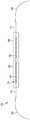
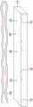
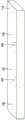
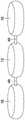
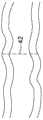
图1是包括具有第一区域和第二区域的磁体组件的分隔装置的一部分的示意性侧面剖视图,该分隔装置示出为处于延伸预分隔构造。1 is a schematic side cross-sectional view of a portion of a partition device including a magnet assembly having a first region and a second region, shown in an extended pre-partition configuration.
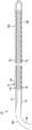
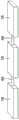
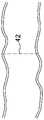
图2是包括具有第一区域和第二区域的磁体组件的分隔装置的一部分的示意性侧面剖视图,该分隔装置示出为处于环状预分隔构造。2 is a schematic side cross-sectional view of a portion of a partition device including a magnet assembly having a first region and a second region, the partition device shown in an annular pre-partitioned configuration.
图3是与中空器官的一部分的壁成任意空间关系的磁体元件的示意性透视图。Figure 3 is a schematic perspective view of a magnet element in arbitrary spatial relationship to a wall of a portion of a hollow organ.
图4是处于延伸预分隔构造的分隔装置的示意性侧面剖视图,其中具有磁体组件的第一区域中的磁体元件和磁体组件的第二区域中的磁体元件的放大视图。Figure 4 is a schematic side cross-sectional view of a partition device in an extended pre-partitioned configuration with a magnet element in a first region of the magnet assembly and an enlarged view of a magnet element in a second region of the magnet assembly.
图5是处于环状预分隔构造的分隔装置的示意性侧面剖视图,其中具有磁体组件的第一区域中的磁体元件和磁体组件的第二区域中的磁体元件的放大视图。Figure 5 is a schematic side cross-sectional view of a partition device in an annular pre-partitioned configuration with a magnet element in a first region of the magnet assembly and an enlarged view of a magnet element in a second region of the magnet assembly.
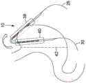
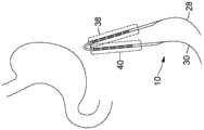
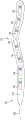
图6是示出用于随后围绕胃的外表面放置的处于延伸预分隔构造的分隔装置的示意性顶部剖视图。Figure 6 is a schematic top cross-sectional view showing the partition device in an extended pre-partition configuration for subsequent placement around the outer surface of the stomach.
图7是图6所示的分隔装置的示意性顶部剖视图,其围绕胃的外表面折叠以放置在环状预分隔构造中。Fig. 7 is a schematic top cross-sectional view of the partition device shown in Fig. 6 folded about the outer surface of the stomach for placement in an annular pre-partition configuration.
图8是示出用于随后围绕胃的外表面放置的处于环状预分隔构造的分隔装置的示意性顶部剖视图。Figure 8 is a schematic top cross-sectional view showing the partition device in an annular pre-partition configuration for subsequent placement around the outer surface of the stomach.
图9是图8所示的分隔装置的示意性顶部剖视图,其被平移以围绕胃的外表面放置。Fig. 9 is a schematic top cross-sectional view of the partition device shown in Fig. 8, translated for placement around the outer surface of the stomach.
图10是图9所示的分隔装置的示意性顶部剖视图,其围绕胃的外表面放置在环状预分隔构造中。Figure 10 is a schematic top cross-sectional view of the partitioning device shown in Figure 9 placed in an annular pre-partitioned configuration about the outer surface of the stomach.
图11是相对于中空器官的一部分的壁以任意空间关系示出的磁体元件的示意性透视图,该磁体元件接收在对应的壳体中。Figure 11 is a schematic perspective view of a magnet element received in a corresponding housing shown in an arbitrary spatial relationship with respect to a wall of a portion of a hollow organ.
图12是相对于中空器官的一部分的壁以任意空间关系示出的磁体组件的一部分的三个磁体元件的示意性透视图,该磁体元件接收在单个壳体中。12 is a schematic perspective view of three magnet elements of a portion of a magnet assembly shown in arbitrary spatial relationship with respect to a wall of a portion of a hollow organ, the magnet elements being received in a single housing.
图13是相对于中空器官的一部分的壁以任意空间关系示出的磁体组件的一部分的三个磁体元件的示意性透视图,该磁体元件接收在具有圆形边缘的对应壳体中,连续的壳体通过壳体的较薄延伸部柔性地连结在一起。Figure 13 is a schematic perspective view of three magnet elements of a portion of a magnet assembly shown in arbitrary spatial relationship with respect to a wall of a portion of a hollow organ, the magnet elements being received in corresponding housings with rounded edges, successive The shells are flexibly joined together by thinner extensions of the shells.
图14是以任意空间关系示出的磁体组件的一部分的三个磁体元件的示意性透视图,相邻的磁体元件通过柔性连接器柔性地连结在一起。Figure 14 is a schematic perspective view of three magnet elements that are part of a magnet assembly shown in arbitrary spatial relationship, adjacent magnet elements being flexibly joined together by flexible connectors.
图15是以任意空间关系示出的磁体组件的一部分的三个磁体元件的示意性透视图,每个磁体元件接收在对应的壳体中,并且相邻的磁体元件通过在对应壳体之间延伸的柔性连接器柔性地连结在一起。Figure 15 is a schematic perspective view of three magnet elements that are part of a magnet assembly shown in arbitrary spatial relationship, each magnet element being received in a corresponding housing, and adjacent magnet elements passing between corresponding housings Extended flexible connectors are flexibly joined together.
图16是以任意空间关系示出的磁体组件的一部分的三个磁体元件的示意性透视图,该磁体元件接收在对应的壳体中,并且磁体元件通过在相邻磁体元件之间延伸的柔性连接器在壳体内柔性地连结在一起。FIG. 16 is a schematic perspective view of three magnet elements that are part of a magnet assembly shown in arbitrary spatial relationship, the magnet elements being received in corresponding housings, and the magnet elements passing through flexible flexible bars extending between adjacent magnet elements. The connectors are flexibly joined together within the housing.
图17是以任意空间关系示出的磁体组件的一部分的三个磁体元件的示意性透视图,每个磁体元件具有圆形边缘,并且相邻的磁体元件通过柔性连接器柔性地连结在一起。17 is a schematic perspective view of three magnet elements of a portion of a magnet assembly shown in arbitrary spatial relationship, each magnet element having rounded edges, and adjacent magnet elements flexibly joined together by flexible connectors.
图18是以任意空间关系示出的磁体组件的一部分的六个磁体元件的示意性透视图,每个磁体元件接收在对应的壳体中,壳体具有斜切边缘,相邻的磁体元件通过在对应壳体之间延伸的柔性连接器柔性地连结在一起,并且磁体元件示出为彼此面对。Figure 18 is a schematic perspective view of six magnet elements that are part of a magnet assembly shown in arbitrary spatial relationship, each magnet element being received in a corresponding housing with chamfered edges through which adjacent magnet elements pass Flexible connectors extending between corresponding housings are flexibly joined together, and the magnet elements are shown facing each other.
图19是以任意空间关系示出的磁体组件的一部分的六个磁体元件的示意性侧面剖视图,每个磁体元件具有斜切边缘,相邻的磁体元件通过柔性连接器柔性地连结在一起,示出的磁体在其之间具有中空器官的壁。19 is a schematic side cross-sectional view of six magnet elements of a portion of a magnet assembly shown in arbitrary spatial relationship, each magnet element having a chamfered edge, adjacent magnet elements flexibly joined together by flexible connectors, showing The resulting magnet has the walls of the hollow organ between them.
图20是包括接收在壳体中的磁体元件的分隔装置的示意性侧面剖视图,该壳体在其器官接触侧上具有细长的平接触表面,分隔装置示出为处于中空器官的壁被压缩在细长的平接触表面之间的分隔构造。Figure 20 is a schematic side cross-sectional view of a spacer device including a magnet element received in a housing having an elongated flat contact surface on its organ-contacting side, the spacer device shown in a hollow organ wall compressed Separation construction between elongated flat contact surfaces.
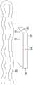
图21是包括磁体元件的分隔装置的示意性顶视图,磁体元件布置成提供沿着分隔装置的长度的弯曲区域。Figure 21 is a schematic top view of a spacer comprising magnet elements arranged to provide a curved region along the length of the spacer.
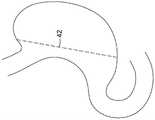
图22是胃的示意性前视图,示出了胃的小弯和大弯之间的整个竖直分隔线。Figure 22 is a schematic front view of the stomach showing the entire vertical division between the lesser and greater curvatures of the stomach.
图23是胃的示意性前视图,示出了胃的小弯和大弯之间的部分上部的竖直分隔线。Fig. 23 is a schematic front view of the stomach showing the partial upper vertical division between the lesser and greater curvatures of the stomach.
图24是胃的示意性前视图,示出了胃的小弯和大弯之间的部分下部的竖直分隔线。Fig. 24 is a schematic front view of the stomach showing a partially inferior vertical division between the lesser and greater curvatures of the stomach.
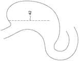
图25是胃的示意性前视图,示出了在其上部区域中的整个上部横向分隔线。Figure 25 is a schematic front view of the stomach showing the entire upper transverse dividing line in its upper region.
图26是胃的示意性前视图,示出了在其下部区域中的整个下部横向分隔线。Figure 26 is a schematic front view of the stomach showing the entire lower transverse dividing line in its lower region.
图27是胃和十二指肠的一部分的示意性前视图,示出了穿过十二指肠的分隔线。Figure 27 is a schematic front view of a portion of the stomach and duodenum showing the dividing line through the duodenum.
图28是远侧结肠的一部分的透明的示意性侧面剖视图,示出了整个分隔线。Figure 28 is a transparent schematic side cross-sectional view of a portion of the distal colon showing the entire dividing line.
图29是近侧结肠的一部分的透明的示意性侧面剖视图,示出了整个分隔线。Figure 29 is a transparent schematic side cross-sectional view of a portion of the proximal colon showing the entire septum.
具体实现方式Specific implementation
治疗与消化道相关的各种医学病症的外科手术可包括改变中空器官的构造,例如食道、胃、胆囊、胆道系统的管道、小肠、结肠或直肠,或者减小这种器官的内腔的尺寸。这种外科手术可针对与消化系统相关的任何手术执行,该手术可包括肥胖外科手术、例如可以例如在癌症治疗、切除手术等的背景下执行的其他消化手术。改变中空器官的构造或减小中空器官的内腔的尺寸可包括通过将器官的相对壁融合在一起而将中空器官分隔成不同的段,而不刺穿组织。为此,可使用分隔装置来实施用于在不刺穿组织的情况下分隔消化道的中空器官的方法。分隔装置可以包括各种特征。应理解,如本文所用,表述“分隔装置”在整个本说明书中可与表述“分隔植入物”互换使用,因为分隔装置配置为植入在患者的腹腔内并且在腹腔内保持一段时间,这段时间可从几天至几周。Surgical procedures to treat various medical conditions related to the digestive tract may include altering the configuration of a hollow organ such as the esophagus, stomach, gallbladder, ducts of the biliary system, small intestine, colon, or rectum, or reducing the size of the lumen of such an organ . Such surgery may be performed for any surgery related to the digestive system, which may include bariatric surgery, such as other digestive procedures that may be performed, for example, in the context of cancer treatment, resection surgery, and the like. Altering the configuration of the hollow organ or reducing the size of the lumen of the hollow organ may include separating the hollow organ into distinct segments by fusing together opposing walls of the organ without piercing the tissue. For this purpose, the method for dividing the hollow organ of the digestive tract without piercing the tissue can be carried out using the dividing device. The spacer can include various features. It should be understood that, as used herein, the expression "separation device" is used interchangeably with the expression "separation implant" throughout this specification, since the separation device is configured to be implanted in the abdominal cavity of a patient and to remain there for a period of time, This period can range from days to weeks.
分隔装置可包括柔性磁体组件,其可插入到患者的腹腔中并且围绕目标中空器官的外表面的一部分定位在腔外。磁体组件的柔性可通过将一系列磁体元件柔性地连接在一起以形成一串磁体元件来赋予。磁体元件中的每一个包括相应的磁体接合侧,并且连续的磁体元件在同一侧上具有其相应的磁体接合侧。在一些实现方式中,一个或多个磁体元件可接收在相应的壳体中,或者该系列磁体元件可一起接收在单个壳体中。The separation device may include a flexible magnet assembly that is insertable into the patient's abdominal cavity and positioned extracavally around a portion of the outer surface of the target hollow organ. Flexibility of the magnet assembly may be imparted by flexibly connecting a series of magnet elements together to form a chain of magnet elements. Each of the magnet elements includes a respective magnet engaging side, and successive magnet elements have their respective magnet engaging sides on the same side. In some implementations, one or more magnet elements may be received in respective housings, or the series of magnet elements may be received together in a single housing.
分隔装置可配置为采用预分隔构造和分隔构造。预分隔构造可便于将分隔装置插入到患者的腹腔中,例如在腹腔镜手术的情况下,并且随后围绕目标中空器官放置。另一方面,分隔构造是可使得能够分隔中空器官的构造。The divider is configurable in a pre-divided configuration and a divided configuration. The pre-partitioned configuration may facilitate insertion of the partitioning device into the abdominal cavity of the patient, such as in the case of laparoscopic surgery, and subsequent placement around the target hollow organ. On the other hand, a partitioning configuration is a configuration that can enable partitioning of a hollow organ.
在预分隔构造中,该多个磁体的磁体接合侧彼此磁性地脱离。为了实现这种预分隔构造,磁体组件纵向地延伸,使得磁体接合侧不彼此面对,并且可纵向地插入到腹腔中,例如作为带。这种类型的预分隔构造可被称为延伸预分隔构造。在预分隔构造的另一实例中,磁体组件可形成U形以获得部分或闭合的环,其中磁体元件的相对的磁体接合侧彼此面对,但是彼此足够远以使磁体元件的相对的磁体接合侧保持磁性地脱离,从而允许部分的环或闭合的环围绕目标中空器官放置。此预分隔构造可被称为环状预分隔构造。In the pre-partitioned configuration, the magnet-engaging sides of the plurality of magnets are magnetically disengaged from each other. To achieve this pre-partitioned configuration, the magnet assembly extends longitudinally such that the magnet-engaging sides do not face each other, and is longitudinally insertable into the abdominal cavity, for example as a belt. This type of pre-partition configuration may be referred to as an extended pre-partition configuration. In another example of a pre-partitioned configuration, the magnet assembly can be formed into a U-shape to obtain a partial or closed loop, wherein the opposing magnet-engaging sides of the magnet elements face each other, but are far enough apart from each other that the opposing magnets of the magnet elements engage The sides remain magnetically disengaged, allowing partial loop or closed loop placement around the target hollow organ. This pre-partition configuration may be referred to as an annular pre-partition configuration.
预分隔构造的选择可取决于磁体组件将围绕其放置的目标中空器官,并且可考虑目标中空器官周围的可用空间。如果磁体组件最初作为带插入,则预构造最终将包括U形的形状,以便放置在目标中空器官周围,同时磁体元件保持磁性地脱离。除了便于将分隔装置插入到腹腔中之外,预分隔构造可便于将磁体组件沿着给定分隔线围绕中空目标中空器官的外表面放置在腔外。在本说明书的上下文中,分隔线对应于目标中空器官的两个部分之间的界限,并且因此对应于分隔的磁体组件的磁体接合侧抵靠放置以分隔目标中空器官的轨迹。The choice of pre-partitioned configuration may depend on the target hollow organ around which the magnet assembly will be placed, and may take into account the space available around the target hollow organ. If the magnet assembly is initially inserted as a band, the pre-configuration will eventually include a U-shape for placement around the target hollow organ while the magnet elements remain magnetically disengaged. In addition to facilitating insertion of the partition device into the abdominal cavity, the pre-partition configuration can facilitate extracavity placement of the magnet assembly around the outer surface of the hollow target hollow organ along a given partition line. In the context of this specification, a separation line corresponds to the boundary between two parts of the target hollow organ, and thus corresponds to the trajectory against which the magnet-engaging sides of the separated magnet assemblies lie to separate the target hollow organ.
一旦分隔装置围绕中空器官的外表面放置,磁体组件就可放置在分隔构造中。在分隔构造中,目标中空器官的每侧上的相对磁体元件设置成足够靠近,使得彼此面对的磁体元件的相对磁体接合侧磁性地联接,以将目标中空器官的壁放在一起并在相对磁体接合侧之间压缩目标中空器官的壁,而不用必须刺穿器官的组织。磁联接将磁体元件保持在位,并且由磁体元件施加在目标中空器官的壁上的压力触发愈合机制,该愈合机制随着时间的推移可导致器官的壁沿着磁体元件的边缘融合。在本说明书的上下文中,术语“融合”可解释为对应于在现在连结以形成单个结构的磁体元件的边缘上得到的愈合组织。最初在磁体接合侧之间被压缩的器官的两个相对壁最终经受缺血性压力坏死,并且在可以从几天延伸到几周的一段时间之后,基本上对应于磁体元件的宽度的空间将最终被限定在中空器官的部分之间。Once the spacer device is placed around the outer surface of the hollow organ, the magnet assembly can be placed in the spaced configuration. In the compartmentalized configuration, opposing magnet elements on each side of the target hollow organ are disposed close enough so that the opposing magnet-engaging sides of the magnet elements facing each other are magnetically coupled to bring the walls of the target hollow organ together and in opposite directions. The walls of the target hollow organ are compressed between the magnet engagement sides without having to pierce the tissue of the organ. The magnetic coupling holds the magnet elements in place, and the pressure exerted by the magnet elements on the walls of the target hollow organ triggers a healing mechanism that over time can cause the walls of the organ to fuse along the edges of the magnet elements. In the context of this specification, the term "fused" may be interpreted as corresponding to the healing tissue obtained on the edges of the magnet elements now joined to form a single structure. The two opposing walls of the organ initially compressed between the magnet-engaging sides eventually undergo ischemic pressure necrosis, and after a period of time that can extend from days to weeks, the space substantially corresponding to the width of the magnet element will Ultimately confined between parts of the hollow organ.
分隔装置配置为在患者的腹腔中保持一段时间,这段时间足以允许愈合过程发生并且足以允许磁体元件的边缘上的器官壁发生融合。监测愈合过程可有利于确定在组织融合发生之后在哪个时刻将分隔装置从患者的腹腔中移出是可行的。The spacer is configured to remain in the patient's abdominal cavity for a period of time sufficient to allow the healing process to occur and sufficient to allow fusion of the organ walls on the edges of the magnet elements. Monitoring the healing process may be useful in determining at what point after tissue fusion has occurred it is feasible to remove the spacer device from the patient's abdominal cavity.
分隔装置还可包括附加特征。例如,分隔装置可包括一个或多个特征,其可有助于帮助将磁体组件放置在腹腔内。这种特征可包括柔性细长构件,例如柔性绳或柔性线,其配置为从磁体组件的一个末端延伸并且其也可被称为前细长构件。柔性细长构件可配置用于与输送导管接合,进而输送导管可用于经由前细长构件将磁体组件携带并导航到腹腔中,并且围绕目标中空器官。The spacer may also include additional features. For example, the spacer device can include one or more features that can help facilitate placement of the magnet assembly within the abdominal cavity. Such a feature may include a flexible elongate member, such as a flexible cord or wire, configured to extend from one end of the magnet assembly and which may also be referred to as a front elongate member. The flexible elongate member can be configured for engagement with a delivery catheter, which in turn can be used to carry and navigate the magnet assembly via the front elongate member into the abdominal cavity and around the target hollow organ.
可选地,分隔装置还可包括在磁体组件的另一末端处的第二柔性细长构件,其与前细长构件相对,并且此第二柔性细长构件可被称为后细长构件。如果期望从患者外部与磁体组件接触,则在磁体组件的植入期间后细长构件是有用的。前细长构件和后细长构件中的任一个或两者也可用于在愈合期期间将分隔装置锚定在患者皮下或外部。Optionally, the spacer means may further comprise a second flexible elongate member at the other end of the magnet assembly, opposite the front elongate member, and this second flexible elongate member may be referred to as a rear elongate member. The rear elongate member is useful during implantation of the magnet assembly if it is desired to make contact with the magnet assembly from outside the patient. Either or both of the anterior and posterior elongated members may also be used to anchor the spacer device subcutaneously or externally to the patient during the healing phase.
现在将更详细地描述分隔装置及相关方法的各种实现方式。Various implementations of the separation device and related methods will now be described in more detail.
磁体组件magnet assembly
磁体元件magnet element
参考图1至图3,示出了分隔装置10的实现方式。分隔装置10包括接收在壳体14中的磁体组件12。磁体组件12包括以柔性方式连接在一起或连结的多个磁体元件16。磁体元件16包括顶侧18、底侧20、横向侧22和纵向侧24。在本说明书的上下文中,磁体元件16的顶侧18是指一旦磁体组件12被植入在患者体内并且围绕目标中空器官的外表面放置时面对目标中空器官的壁26的一侧。在所示的实现方式中,分隔装置10还包括在每个末端处的柔性细长构件,即,前细长构件28和后细长构件30。另外,将磁体元件16接收在其中的壳体14也是柔性的。Referring to Figures 1 to 3, an implementation of the
在图1中,分隔装置10处于预分隔构造,其中分隔装置10纵向地延伸,使得磁体组件12的末端彼此间隔开并且相对。这种类型的预分隔构造可被称为延伸预分隔构造。在图2中,分隔装置10也处于预分隔构造中,该预分隔构造也可被称为环状预分隔构造。在环状预分隔构造中,磁体组件12以U形自身折叠以形成部分的环或闭合的环,这取决于预期的应用。磁体组件12的预分隔构造的选择可取决于待治疗的中空器官和所考虑的插入方法的选择。如上所述,如果磁体组件12最初作为例如图1所示的带插入,则预分隔构造最终包括形成部分或闭合的环状的U形,以便围绕目标中空器官放置,同时磁体元件16保持磁性地脱离。换句话说,磁体组件12的预分隔构造的一个特征是磁体元件16磁性地脱离,并且磁体组件12可采用磁体元件16磁性地脱离的各种构造。除了便于将分隔装置10插入到腹腔中之外,预分隔构造还可便于磁体组件12沿着给定分隔线42围绕目标中空器官的外表面放置在腔外。In FIG. 1 , the
磁体组件12的磁体元件16可以是任何类型的合适磁体。在一些实现方式中,磁体元件16可根据其吸引力,即根据将施加在组织的表面区域上的压力来选择,该表面区域将最终被压缩在磁性联接的磁体元件16之间。影响磁体元件16的吸引力的因素可包括磁体元件16的形状、磁体元件16的厚度、制造磁体元件16的材料等。材料的实例可包括钕磁体(例如,NdFeB磁体)、稀土磁体和铁氧体磁体。The
现在参考图4和图5,磁体元件16中的每一个可以是偶极磁体,其具有穿过磁体元件16的厚度的磁极,使得磁体元件16包括在其一侧上的第一磁极34和在其另一侧上的第二磁极36,第二磁极36不同于第一磁极34。磁体元件16的一侧对应于磁体联接侧32,其是一旦将磁体组件12安装在目标中空器官的外表面周围,磁体元件16的将最终面对待治疗的中空器官的组织26的一侧,该外表面在上面也被称为磁体元件16的顶侧18。Referring now to FIGS. 4 and 5 , each of the
磁体元件16沿着磁体组件12的长度策略性地定位,以获得磁体组件12的期望功能。参考图1至图10,示出了磁体组件12的第一区域38和第二区域40。磁体组件12的第一区域38对应于磁体组件12的一部分,当分隔装置10处于例如图1中的延伸预分隔构造时,通过将前细长构件28引导到腹腔中,例如图6中,该部分将首先插入到患者的腹腔中。然后,磁体组件12的第一区域38将是在后部位置中围绕目标中空器官的外表面翻转的区域,例如图7所示。第二区域40对应于磁体组件12的一部分,当磁体组件12插入到腹腔中时,该部分跟随第一区域38,然后保持在前部位置而不围绕目标中空器官的外表面翻转,例如图7所示。The
参考图8至图10,在磁体组件12已经处于环状预分隔构造的实现方式中,磁体组件12的第一区域38和第二区域40可在腹腔中并排导航而不是延伸。在这种实现方式中,磁体组件12的第一区域38可以说是对应于磁体组件12的一旦被插入患者的腹腔中将处于后部位置的部分,并且第二区域40可以说是对应于磁体组件12的一旦被插入患者的腹腔中将处于后部位置的部分,或反之亦然。Referring to FIGS. 8-10 , in implementations in which the
返回参考图4和图5,第一区域38包括一系列磁体元件16,每个磁体元件具有彼此之间具有相同磁极(即,第一区域磁极)的磁体联接侧32,并且第二区域40包括一系列磁体元件16,每个磁体元件也具有彼此之间具有相同磁极(即,第二区域磁极)的磁体联接侧32,但是该磁极不同于第一区域38的磁体元件16的磁体联接侧32的磁极。磁体联接侧32对应于上述磁体元件16的顶侧18,即,面对中空器官的壁的一侧。例如,如图4所示,分隔装置10处于延伸预分隔构造,并且磁体组件12的第二区域40与第一区域38纵向地间隔开。第一区域38的磁体元件16的磁体联接侧32具有北极,并且第二区域40的磁体元件16的磁体联接侧32具有南极。类似地,在图5中,分隔装置10处于环状预分隔构造,并且第一区域38的磁体元件16的磁体联接侧32具有北极,而第二区域40的磁体元件16的磁体联接侧32具有南极。Referring back to FIGS. 4 and 5 , the
磁体组件12的此构造使得磁体组件12的第一区域38和第二区域40的磁体元件16能够彼此吸引,并且一旦磁体组件12处于分隔构造中就磁性地联接,其中磁体元件16具有不同的磁体联接侧32,这取决于其沿着磁体组件12所处的区域38、40。This configuration of the
如上所述,磁体元件16可具有各种形状和尺寸。磁体元件16的形状和/或尺寸的选择可取决于分隔装置10将围绕其植入的目标中空器官。例如,对于诸如胃的基本上比小肠的部分(例如十二指肠、空肠或结肠)大且平的器官,细长磁体元件16可用作磁体组件12的一部分。另一方面,磁体元件16的长度可保持足够小以允许磁体组件12围绕胃或另一目标中空器官的外表面导航。例如,在一些实现方式中,设计为分隔胆管的磁体元件16可以具有范围从大约2mm至大约10mm的尺寸,而设计为分隔胃的磁体元件16可以具有范围从大约2cm至大约10cm的尺寸。作为磁体元件16的尺寸和目标中空器官之间的一般关系,设计用于分隔较厚和/或较大的中空器官的磁体元件16通常可大于设计用于较小和/或较薄的中空器官的磁体元件16。这种一般关系考虑了这样的原理,即较大和/或较厚的中空器官可以经受由较大磁的体元件16所赋予的较大的吸引力,以实现中空器官的壁的预期压缩以及随后围绕磁体元件16的边缘的愈合。在一些实现方式中,对于以环状预分隔构造配置的磁体组件12,磁体元件16可以比对于以延伸预分隔构造配置的磁体组件12更长,因为在环状预分隔构造中,磁体组件12已经自身折叠。As noted above, the
另外,尽管图3和图11至图16中给出例子中的磁体组件12的一部分的磁体元件16被表示为基本上矩形的,但是应理解,磁体元件16可包括锥形边缘、斜切边缘、圆形边缘等。磁体元件16也可具有椭圆、体育场形状、圆形、三角形、矩形、八边形或任何其他适于本文描述的应用的形状。Additionally, although the
例如,图17示出了磁体组件12的一部分的一系列磁体元件16的实例,每个磁体元件16具有圆形边缘和基本上椭圆形形状。在一些实现方式中,具有圆形边缘或其他非尖锐特征的磁体元件16可有助于便于相邻磁体元件16之间的运动,并且因此为磁体组件12提供增强的柔性。For example, FIG. 17 shows an example of a series of
图18示出了磁体组件12的一部分的一系列磁体元件16的实例,每个磁体元件16接收在具有斜切边缘17的壳体中,磁体元件16示出为彼此面对,如当放置在目标中空器官的壁的任一侧上时的情况那样。18 shows an example of a series of
图19示出了磁体组件12的一部分的磁体元件16的实例,每个磁体元件16具有斜切边缘19。在一些实现方式中,如图18或图19所示,当磁体元件16或壳体14包括斜切边缘时,磁体元件16的磁体联接侧32或壳体14的器官接触侧44与远离中空器官的壁定位的一侧(即底侧20)相比可具有较小的表面积。此构造可允许在相对的磁体元件16的磁体联接侧32之间或在相对的壳体14的器官接触侧44之间具有较小的压缩表面,使得如果缺血性坏死比最初预见的更快发生,则磁体元件16或壳体14的具有较大表面积的一侧可提供锚定物以防止磁体元件16或壳体14的不期望的运动。在一些实现方式中,磁体元件16或壳体14的具有较大表面积的一侧也可有助于防止磁体元件16或壳体14穿过中空器官的壁的发生缺血性坏死的区域。FIG. 19 shows an example of the
在一些实现方式中,包括在磁体组件12的第一区域38中的磁体元件16的磁体接合侧32可具有与包括在磁体组件12的第二区域40中的磁体元件16的磁体接合侧32互补的形状。例如,包括在第一区域38中的磁体元件16的磁体接合侧32可包括凹部,并且包括在第二区域40中的磁体元件16的磁体接合侧32可包括配置为配合在凹部内的凸起。在一些实现方式中,凹部与对应的凸起或具有互补形状的其他特征的接合可有助于使第一区域38的磁体元件16与第二区域40的磁体元件稳定。在一些实现方式中,包括在磁体组件12的第一区域38中的磁体元件16的边缘可包括开槽边缘,并且包括在磁体组件12的第二区域40中的磁体元件16的边缘可包括与第一区域38的磁体元件16的开槽边缘互补的开槽边缘。In some implementations, the magnet-engaging
在一些实现方式中,如上所述,磁体元件16的吸引力可根据目标中空器官沿着分隔线42的厚度和/或组成来选择。例如,磁体元件16的吸引力可与目标中空器官壁的厚度成比例。此原理可从一个目标中空器官应用于另一个目标中空器官,或者在相同的目标中空器官内。例如,胃的壁比十二指肠或小肠的另一部分的壁厚,设计为用于胃的磁体组件12的磁体元件16的吸引力可以比设计为用于十二指肠的磁体组件12的高。In some implementations, the attractive force of
当壁厚在相同的目标中空器官内变化时,磁体元件16的吸引力可在第一区域38内变化,并且因此在第二区域40内变化,使得一旦处于分隔构造,沿着磁体组件12的长度施加在目标中空器官的组织上的压力也可变化。例如,当目标中空器官是胃时,胃的壁厚在胃底附近比在胃的主体或胃窦中的壁厚更大。因此,与磁体组件12的磁体元件16在磁体组件12的下部(即,远离第一区域38到第二区域40的过渡)中的吸引力相比,磁体组件12的磁体元件16可被选择为在磁体组件12的上部(即,更靠近从第一区域38到第二区域40的过渡)中具有更高的吸引力。在与胃相关的实例的上下文中,相关术语“上部”和“下部”用于指磁体组件12的一旦被植入在胃的外表面周围并且当患者站起来时的部分,其中“上部”部分对应于胃的在胃底区域中的部分,并且“下部”部分对应于胃的在主体或胃窦区域中的部分。As the wall thickness varies within the same target hollow organ, the attractive force of the
在目标中空器官主要由肌肉纤维组成的实现方式中,例如远侧结肠或直肠,磁体元件16的吸引力可以被选择为高于磁体组件12的磁体元件16的吸引力,该磁体组件设计用于小肠的部分,例如十二指肠、空肠或回肠。In implementations where the target hollow organ is primarily composed of muscle fibers, such as the distal colon or rectum, the attractive force of the
磁体元件16的吸引力也可被选择为便于将分隔装置10放置和植入在目标中空器官周围。例如,在一些实现方式中,磁体元件16之间的吸引力可以足够弱以使得在沿着分隔线42放置分隔装置10期间能够磁性地脱离磁体元件16,使得试错法能到达磁体组件12的期望位置。The attractive force of the
此外,磁体元件16的吸引力也可根据计划的愈合期来选择。例如,磁体元件16之间的吸引力可以足够弱以有利于几天或几周范围内的愈合期。较长的愈合期可便于获得良好融合的壁和沿着分隔线逐渐施加压力,而具有太强吸引力的磁体元件16在磁体元件16的磁体联接侧32之间可引起快速缺血性压力坏死,这可损害磁体元件16的边缘上的愈合机制,并且可导致目标中空器官的组织中的开口。在一些实现方式中,可选择磁体元件16的吸引力,使得愈合过程在植入分隔装置10之后2至7周的时间段内发生。在一些实现方式中,选择磁体元件16的吸引力,使得愈合过程在植入分隔装置10之后3至6周的时间段内发生。根据期望的结果和目标中空器官,其他持续时间的愈合期也是可能的。Furthermore, the attractive force of the
应注意,在一些实现方式中,目标中空器官的壁沿着分隔线42经受的缺血性压力坏死可能足以导致目标中空器官沿着分隔线42与磁体元件16的边缘上的融合组织的分隔。在其他实现方式中,目标中空器官的壁沿着分隔线42经受的缺血性压力坏死可以足以导致目标中空器官的分隔段的分离。因此,磁体元件16的吸引力也可根据是否需要目标中空器官的分隔或目标中空器官的一部分的分离来选择。It should be noted that in some implementations, the ischemic pressure necrosis experienced by the wall of the target hollow organ along the
随着时间的推移监测愈合过程也对在植入分隔装置10之后在目标中空器官上获得的结果起作用,并且这种监测可帮助确定在哪个时刻继续移除分隔装置10以获得关于目标中空器官的分隔或目标中空器官的一部分的分离的期望结果。Monitoring the healing process over time also contributes to the results obtained on the target hollow organ after implantation of the
在一些实现方式中,磁体元件16的尺寸可沿着磁体组件12的长度变化。磁体尺寸的这种变化可有助于增加磁体组件12在其选定部分中的灵活性,特别是当磁体组件12包括单独接收在壳体14中或没有壳体的多个磁体元件16时,如图12至图15和图18所示。例如,磁体组件12可包括在从第一区域38到第二区域40的过渡附近的较小磁体元件16。设置在此过渡区域附近的较小磁体元件16可通过如图7所示的便于磁体组件12的折叠而有助于便于采用环状预分隔构造和分隔构造。在从第一区域38到第二区域40的过渡附近的较小磁体元件16可因此便于分隔装置10的放置。在一些实现方式中,远离此过渡区域的较大磁体植入物,特别是在长度方面,可便于获得连续分隔线42。In some implementations, the dimensions of the
壳体case
参考图11至图16和图18,在一些实现方式中,磁体元件16可接收在壳体14中。在图11中,单个磁体元件16接收在对应的壳体14中,而在图12中,多个磁体元件16接收在单个壳体14中。在其他实现方式中,一定数量的磁体元件16可接收在壳体16中。例如,2至10个磁体元件16可接收在单个壳体14中。在这种实现方式中,壳体14中的磁体元件16的数量可受到其尺寸的影响,即,磁体元件16越小,在具有给定长度的壳体14中可接收的磁体元件16越连续。Referring to FIGS. 11-16 and 18 , in some implementations, the
如上所述,壳体14包括器官接触侧44,当分隔装置10处于分隔构造时,该器官接触侧与目标中空器官的组织接触。在一些实现方式中,壳体14的器官接触侧44包括细长的平接触表面,以便于与压缩在其之间的组织均匀接触。壳体14可配置为提供防止损伤的表面,其可有助于避免对周围组织的损伤。壳体14可包括圆形边缘和/或在其壁之间的锥形过渡。在一些实现方式中,壳体14可具有椭圆或体育场形状。图13示出了接收在具有圆形边缘的相应壳体14中的磁体元件16的实例,连续的壳体14通过壳体14的较薄延伸部46(也称为壳体14的连接部分)柔性地连结在一起。下面提供了关于此方面的附加细节。As noted above, the
在一些实现方式中,包括在第一区域38中的磁体元件16的壳体14的器官接触侧44可包括凹部,并且包括在第二区域40中的磁体元件16的壳体14的器官接触侧44可包括配置为配合在凹部内的凸起。凹部与对应凸起或具有互补形状的其他特征经由壳体14的接合可有助于使第一区域38的磁体元件16与第二区域40的磁体元件稳定。在一些实现方式中,包括在磁体组件12的第一区域38中的磁体元件16的壳体14的器官接触侧44的边缘可包括开槽边缘,并且包括在磁体组件12的第二区域40中的磁体元件16的壳体14的器官接触侧44的边缘可包括与第一区域38的壳体14中的一个互补的开槽边缘。In some implementations, the organ-contacting
在一些实现方式中,壳体14可有助于将由磁体元件16施加的力扩散到更大的区域上,这可根据应用和/或在目标中空器官上而是有利的。壳体14可由生物相容材料制成。在一些实现方式中,壳体14可由金属制成,例如不锈钢、钛或其他医疗植入级金属。或者,壳体14可以由硅树脂或其他医用植入级聚合物制成。在某些情况下,壳体14由SilasticTM制成,其是柔性硅树脂弹性体。在一些实现方式中,壳体14可在磁体元件16周围提供保护涂层,其进而可帮助防止腐蚀并保持磁体元件16的完整性。壳体14的纹理,特别是器官接触侧44上的纹理可被选择为一旦处于分隔构造就向磁体组件12提供增加的稳定性。例如,植入物在壳体14的器官接触侧44上的表面粗糙度可高于其相对侧上的表面粗糙度。壳体14的器官接触侧44的表面粗糙度就可以是有益的:一旦磁体元件16磁性地联接,防止由于剪切力而产生的磁性脱离。In some implementations,
相邻磁体元件之间的柔性连接Flexible connections between adjacent magnet elements
如上所述,磁体组件12包括柔性地彼此串联连接的磁体元件16。可以各种方式实现将磁体元件16柔性地连接在一起。下面提供了实例。As noted above, the
参考图13,多个磁体元件16可接收在相应的单个壳体14中,并且壳体14可包括在相邻的磁体元件16之间的部分,其适于为磁体组件12提供增加的灵活性。如图13所示,这些部分46可以更窄或更薄,以增加其运动自由度,同时保持足够坚固以避免断裂。在一些实现方式中,壳体14的在相邻磁体元件16之间的部分46可由与壳体14的其余部分的材料不同的材料制成,以受益于此不同材料的特定特性,特别是在其柔性方面。在一些实现方式中,相邻磁体元件16之间的壳体14的部分46可在某一平面中提供一定的运动范围,而在另一平面中提供受限的运动范围。例如,可能期望使磁体元件16相对于彼此移动以使得磁体组件12能够围绕目标中空器官折叠,而可能不太期望使磁体元件16相对于彼此横向移动,因为磁体元件16的横向移动可有助于使磁体元件16转向离开分隔线42。Referring to FIG. 13 , a plurality of
参考图14,当磁体元件16周围没有设置壳体时,磁体元件16可在其每个横向侧上包括挂钩(未示出),并且经由柔性连接器48(例如带)彼此连接。柔性连接器48的类型可选择为根据给定的运动范围为磁体组件12提供足够的移动性和柔性,使得磁体组件12可容易地被引导到其在腹腔中的目的地并围绕目标中空器官放置。例如,当目标中空器官基本上是圆柱形的,例如十二指肠或结肠时,这种器官的周长与胃的尺寸相比可相对较小,并且具有增加的柔性的磁体组件12以便于引导分隔装置10围绕器官并将其保持在适当位置可能是有益的。Referring to FIG. 14 , when no housing is provided around the
参考图15,柔性连接器48可设置在单独容纳在相应壳体14中的相邻磁体元件16之间。在这种实现方式中,接合部分,例如挂钩,可设置在壳体14的横向侧上。在一些实现方式中,接合部分可与壳体14成一体。壳体14因此可模制为在其每个横向侧上包括挂钩的单件单元,其中磁体元件16接收在壳体14中,并且多个磁体元件16中的相邻磁体元件可经由与相应挂钩接合的柔性连接器48彼此柔性地连接。或者,可在壳体14的横向侧上设置挂钩,并且柔性连接器48可从另一侧延伸以与相邻壳体14的挂钩柔性地连接。Referring to FIG. 15 ,
在其他实现方式中,参考图16,磁体元件16可通过集成在壳体14内而柔性地彼此连接,并且柔性连接器48也可设置在壳体14内的相邻磁体元件16之间。在图16所示的实现方式中,与图15所示的实现方式相比,柔性连接器48因此示出为集成在壳体14内。In other implementations, referring to FIG. 16 ,
应理解,如图12所示,磁体组件12的柔性可通过磁体元件16周围的壳体14本身的存在来提供,例如给定制造壳体14的材料的柔性。It will be appreciated that, as shown in FIG. 12 , the flexibility of the
相邻磁体元件16之间的距离可选择为对磁体组件12的最终柔性有影响。在一些实现方式中,当确定相邻磁体元件16之间的距离时,应注意保持以这种方式获得的磁体组件12的柔性和对最终分隔线42的影响之间的平衡,因为可能彼此相距太远的连续磁体元件16可能导致不太均匀的分隔线42。在一些实现方式中,相邻磁体元件16之间的距离可沿着磁体组件12的长度变化,类似于上面关于磁体元件16的尺寸所描述的。例如,在一些实现方式中,位于从第一区域38到第二区域40的过渡附近的磁体元件16可以被设置得稍微更远,以在此过渡区域中向磁体组件12提供增强的柔性。在一些实现方式中,磁体元件16的尺寸和相邻磁体元件16之间的距离之间的相互作用可有助于为磁体组件12和期望的分隔线42提供增强的柔性。在一些实现方式中,只要保持磁体组件12的柔性,尽可能彼此靠近地设置的磁体元件16就可以是有利的。在该方面,如上所述,具有圆形边缘的磁体元件16或壳体14可有利于使磁体元件16或壳体14靠近在一起,但是不损害磁体组件12的柔性。应注意,这些只是实例,其说明了各种构造可能对磁体组件12的柔性所具有的效果,并且可实施磁体组件12的多种构造,以实现磁体组件12的期望柔性和期望分隔线42的组合以及磁体元件16的边缘上的组织的对应愈合。The distance between
分隔装置的定位和植入Positioning and Implantation of Spacer Devices
现在参考图20至图29,现在将描述与在给定目标中空器官和不同目标中空器官的不同位置处植入分隔组件相关的实现方式。Referring now to FIGS. 20-29 , implementations related to implanting a partition assembly at different locations for a given target hollow organ and different target hollow organs will now be described.
图20示出了处于分隔构造的分隔装置10的一个实例,其中目标中空器官的相对壁被压缩在壳体14的器官接触侧44之间,并且来自第一区域38的磁体元件16的磁体接合侧32磁性地联接到来自第二区域40的磁体元件16的磁体接合侧32。分隔装置10可沿着期望的分隔线42被植入,并且下面提供了分隔线42的位置的实例。20 shows an example of the
图21示出了处于分隔构造的分隔装置10的实例,示出了分隔装置10的顶视图。图21所示的分隔装置10包括弯曲区域21。弯曲区域21例如可通过壳体14的形状或通过磁体元件16连结在一起的方式来提供。在一些实现方式中,还可提供弯曲的磁体元件16。弯曲区域21的形状和位置可以变化,并且图21仅是为了说明目的而示出的实例。分隔装置10的这种类型的构造,即包括弯曲区域21的分隔装置12,对于将分隔装置12放置在例如肿瘤周围或横结肠的一部分周围可以是有利的。FIG. 21 shows an example of the
图22示出了从胃底延伸到胃窦以及胃的小弯和大弯之间的整个竖直分隔线42的实例,以在磁体元件16的边缘上的组织愈合之后获得胃的竖直套管构造。分隔线42的位置可根据期望获得的胃的区域的体积而变化。在这种实现方式中,可通过将处于延伸预分隔构造的分隔装置10插入到腹腔中并且将其围绕胃的外表面放置,将磁体组件12放置在胃的外表面周围的期望位置处,如图7所示。磁体组件12的插入和引导可以腹腔镜方式进行以用于微创手术,这也有利地使得能够最小地干扰胃周围的结缔组织、动脉、静脉和其他器官。当将磁体组件12以延伸预分隔构造插入到腹腔中时,磁体组件12可围绕胃的外表面导航,并且与期望的分隔线42对准。一旦获得磁体组件12的正确对准,就可使磁体组件12的第一区域38的磁体元件16足够紧密地接近磁体组件12的第二区域40的磁体元件16,使得第一区域38的磁体元件16的磁体接合侧可磁性联接到第二区域40的磁体元件16的磁体接合侧。如上所述,磁体元件16的吸引力可被选择为使得能够试错,直到实现磁体组件12的正确放置。22 shows an example of the entire
或者,磁体组件12的放置可在开放式手术期间执行。在这种情况下,磁体组件12可设置成以延伸预分隔构造或以环状预分隔构造围绕胃放置。也可使用多种其他技术来定位和植入磁体组件12。例如,图像引导手术(例如,超声、磁共振成像、计算机断层摄影等)和柔性内窥镜检查是可用于将磁体组件12充分地插入和/或定位在目标中空器官周围的技术。应注意,也可使用允许将磁体组件12插入和/或放置在目标中空器官的外表面周围的任何其他合适的技术。Alternatively, placement of
参考图23和图24,在一些实现方式中,分隔线42可沿着胃的给定部分基本上竖直地延伸,即,不跨过胃的整个高度。在图23所示的实现方式中,分隔线42可被称为上部竖直分隔线,而在图24所示的实现方式中,分隔线42可被称为下部竖直分隔线。可实施与上述用于图18所示的全高度分隔线42的技术类似的技术,以便围绕胃的外表面放置磁体组件12。Referring to Figures 23 and 24, in some implementations, the dividing
参考图25和图26,在一些实现方式中,分隔线42可沿着胃的上部(图25)或沿着胃的下部(图26)基本上横向地延伸,从而提供胃的完全横向分隔。完全横向分隔可导致可与消化道的另一部分连结的胃囊的形成。这种类型的分隔可以与用不同的装置形成吻合结合使用,以保持胃肠连续性,其中消化道的另一部分连结到胃的分隔部分。例如,整个上部分隔线42可用于形成Roux-en-Y胃旁路,例如横结肠后Roux-en-Y胃旁路、横结肠前Roux-en-Y胃旁路,以及长肢Roux-en-Y胃旁路、迷你胃旁路、单吻合胃旁路、十二指肠开关、单吻合开关,以及其他旁路。在例如图25和图26所示的实现方式中,由于消化道的连续性质,可指示处于延伸预分隔的磁体组件12,以便磁体组件12围绕胃的外表面完全横向放置。Referring to FIGS. 25 and 26 , in some implementations, the line of
图27示出了位于幽门括约肌附近、围绕位于近侧十二指肠的区域中的消化道的一部分的外表面的分隔线42的实现方式。在其他实现方式中,分隔线42可位于消化道的位于远侧十二指肠区域中的部分的外表面周围。在另一些实现方式中,分隔线42可位于沿着十二指肠的任何肠环上。在另一些实现方式中,分隔线42可位于小肠的任何其他部分上,例如空肠或回肠。与上面关于图25和图26的描述类似,由于消化道的连续性质,处于延伸预分隔的磁体组件12被指示为围绕十二指肠的外表面放置。Fig. 27 shows an implementation of a
图28示出了横向延伸跨过远侧结肠的一部分的分隔线42的实现方式,其中壁厚大于图29所示的壁厚,图29示出了横向延伸跨过近侧结肠的一部分的分隔线42的实现方式。FIG. 28 shows an implementation of a
用于植入分隔装置的方法Methods used to implant spacer devices
现在将更详细地描述使用如本文所述的分隔装置分隔患者的消化道的中空器官的方法。A method of partitioning a hollow organ of a patient's digestive tract using a partitioning device as described herein will now be described in more detail.
分隔装置包括前细长构件和后细长构件,其中磁体组件在其之间延伸。磁体组件包括柔性地串联连接的多个磁体元件。前细长构件可包括任何类型的柔性构件。在一些实现方式中,前细长构件可配置为与输送导管接合以允许细长构件通过腹腔镜导航。在一些实现方式中,后细长构件也可包括任何类型的柔性构件,其可以可选地配置为与输送导管接合或保持在患者外部或皮下位置中。或者,可省略前细长构件和后细长构件中的至少一个。The spacer includes a front elongated member and a rear elongated member with the magnet assembly extending therebetween. The magnet assembly includes a plurality of magnet elements flexibly connected in series. The front elongated member may comprise any type of flexible member. In some implementations, the front elongated member can be configured to engage a delivery catheter to allow the elongated member to be navigated laparoscopically. In some implementations, the rear elongated member may also comprise any type of flexible member that may optionally be configured to engage a delivery catheter or be retained in a location external to the patient or subcutaneously. Alternatively, at least one of the front and rear elongated members may be omitted.
当存在前细长构件时,该方法可包括将分隔装置的前细长构件和磁体组件插入到患者的腹腔中。由于分隔装置是配置为在患者的腹腔中保持一定时间段的植入物,所以可以在插入到患者的腹腔中之前对分隔装置进行消毒。为了插入到患者的腹腔中,磁体组件可处于延伸预分隔构造或处于环状预分隔构造。然后,将磁体组件经由分隔装置的前细长构件(当存在时)引导到目标中空器官,以将磁体组件围绕中空器官的外表面的至少一部分定位在腔外,使得磁体组件的前部和磁体组件的后部彼此面对。可使用各种技术将磁体组件插入到患者的腹腔中,并且将磁体组件围绕目标中空器官的外表面放置。这些技术可包括例如腹腔镜手术、开放式手术、图像引导手术和柔性内窥镜检查。当磁体组件的前部面对磁体组件的后部时,来自磁体组件的第一区域的磁体元件的磁体接合侧面对来自磁体组件的第二区域的磁体元件的磁体接合侧,同时磁体元件在环状预分隔构造中保持磁性地脱离,以便于磁体组件沿着期望的分隔线放置。When the anterior elongated member is present, the method may include inserting the anterior elongated member and magnet assembly of the spacer into the abdominal cavity of the patient. Since the spacer device is an implant configured to remain in the patient's abdominal cavity for a certain period of time, the spacer device may be sterilized prior to insertion into the patient's abdominal cavity. For insertion into the patient's abdominal cavity, the magnet assembly may be in an extended pre-divided configuration or in an annular pre-divided configuration. The magnet assembly is then guided to the target hollow organ via the front elongate member of the spacer (when present) to position the magnet assembly outside the lumen around at least a portion of the outer surface of the hollow organ such that the front portion of the magnet assembly and the magnet The rears of the components face each other. Various techniques may be used to insert the magnet assembly into the patient's abdominal cavity and place the magnet assembly around the outer surface of the target hollow organ. These techniques may include, for example, laparoscopic surgery, open surgery, image-guided surgery, and flexible endoscopy. When the front of the magnet assembly faces the rear of the magnet assembly, the magnet engaging side of the magnet element from the first region of the magnet assembly faces the magnet engaging side of the magnet element from the second region of the magnet assembly while the magnet element is in the ring Magnetically disengaged in a pre-partitioned configuration to facilitate placement of the magnet assembly along the desired parting line.
一旦磁体组件的两侧上的磁体元件根据需要沿着分隔线对准,就可使磁体元件以分隔构造更靠近在一起。在分隔构造中,第一区域的磁体元件磁性地联接第二区域的磁体元件,即,彼此面对的磁体元件经由其相应的磁体接合侧磁性地联接,以在其之间压缩中空器官的相对壁。在一些实现方式中,当磁体元件接收在壳体中时,壳体包括器官接触侧,并且目标中空器官的相对壁被压缩在壳体的彼此面对的器官接触侧之间。在一些实现方式中,壳体的器官接触侧可以是细长的平接触表面。Once the magnet elements on both sides of the magnet assembly are aligned along the separation line as desired, the magnet elements can be brought closer together in the spaced configuration. In the compartmentalized configuration, the magnet elements of the first region are magnetically coupled to the magnet elements of the second region, i.e., the magnet elements facing each other are magnetically coupled via their respective magnet engagement sides to compress opposing sides of the hollow organ therebetween. wall. In some implementations, when the magnet element is received in the housing, the housing includes organ-contacting sides, and opposing walls of the target hollow organ are compressed between the organ-contacting sides of the housing facing each other. In some implementations, the organ-contacting side of the housing can be an elongated planar contacting surface.
在一些实现方式中,可将前细长构件带到后细长构件附近,并且前细长构件和后细长构件中的一个或两个可放置在患者的外部或者可保持在经皮位置。在其他实现方式中,前细长构件和后细长构件可以是与磁体组件可滑动地接合的连续细长构件,并且在将磁体组件以分隔构造植入之后,前细长构件和后细长构件就可通过拉动前细长构件和后细长构件中的一个而从患者的腹腔移除。In some implementations, the anterior elongated member can be brought adjacent to the posterior elongated member, and one or both of the anterior and posterior elongated members can be placed external to the patient or can remain in a percutaneous location. In other implementations, the anterior and posterior elongated members can be a continuous elongated member that is slidably engaged with the magnet assembly, and after the magnet assembly is implanted in a spaced configuration, the anterior and posterior elongated members The members can then be removed from the patient's abdominal cavity by pulling on one of the front and rear elongated members.
然后,在将磁体组件以分隔构造植入在目标中空器官周围之后,将磁体组件保持植入一段足以允许中空器官的相对壁融合在一起的愈合期,同时磁体元件磁性地联接在一起。在一些实现方式中,愈合期可从2周延长到7周。在一些实现方式中,可执行对愈合过程的监测,以确定在哪个时刻目标中空器官的壁被很好地融合在一起,即,在两个分隔部分之间没有泄漏。愈合期的持续时间可取决于例如目标中空器官、磁体组件的构造、患者的病症,以及各种其他因素。Then, after the magnet assembly is implanted in the spaced configuration around the target hollow organ, the magnet assembly remains implanted for a healing period sufficient to allow the opposing walls of the hollow organ to fuse together while the magnet elements are magnetically coupled together. In some implementations, the healing period can be extended from 2 weeks to 7 weeks. In some implementations, monitoring of the healing process can be performed to determine the moment at which the walls of the target hollow organ are well fused together, ie, there is no leak between the two separated parts. The duration of the healing period may depend on, for example, the target hollow organ, the configuration of the magnet assembly, the patient's condition, and various other factors.
一旦目标中空器官的壁很好地融合在一起并且完成愈合,就可从患者的腹腔移除磁体组件。用于移除磁体组件的方法可根据分隔装置的设计而变化。可通过可选地利用输送导管将前细长构件和后细长构件中的一个拉出患者而将磁体组件从目标中空器官和腹腔经腹腔镜移除。还可通过直接将磁体组件从患者体内拉出而将磁体组件从目标中空器官和腹腔经腹腔镜移除,可选地也利用输送导管。在一些实现方式中,磁体组件可在开放式手术期间被移除。此外,可使用各种技术从患者的腹腔移除磁体组件,这些技术可以与先前用于将磁体组件插入并放置在目标中空器官周围的技术相同或不同,并且可包括例如腹腔镜手术、开放式手术、图像引导手术和柔性内窥镜检查。Once the walls of the target hollow organ are well fused together and healing is complete, the magnet assembly can be removed from the patient's abdominal cavity. The method used to remove the magnet assembly can vary depending on the design of the spacer. The magnet assembly may be removed laparoscopically from the target hollow organ and abdominal cavity by pulling one of the anterior and posterior elongated members out of the patient, optionally using a delivery catheter. The magnet assembly can also be removed laparoscopically from the target hollow organ and abdominal cavity by pulling the magnet assembly directly out of the patient, optionally also using a delivery catheter. In some implementations, the magnet assembly is removable during open surgery. In addition, the magnet assembly can be removed from the patient's abdominal cavity using various techniques which may be the same or different from those previously used to insert and place the magnet assembly around the target hollow organ and which may include, for example, laparoscopic surgery, open Surgery, image-guided surgery, and flexible endoscopy.
本文已经描述和示出了几个替代的实现方式和实例。上述技术的实现方式仅旨在是示例性的。本领域普通技术人员将理解各个实现方式的特征,以及部件的可能组合和变化。本领域普通技术人员还将理解,可以与本文公开的其他实现方式的任何组合来提供任何实现方式。应理解,在不脱离本技术的中心特征的情况下,本技术可以以其他特定形式来实施。因此,本实现方式和实例在所有方面都被认为是说明性的而非限制性的,并且该技术不限于本文给出的细节。因此,虽然已经示出和描述了特定的实现方式,但是可以想到许多修改。Several alternative implementations and examples have been described and illustrated herein. Implementations of the techniques described above are intended to be exemplary only. Those of ordinary skill in the art will appreciate the features of the various implementations, as well as possible combinations and variations of components. Those of ordinary skill in the art will also understand that any implementation may be provided in any combination with other implementations disclosed herein. It should be understood that the technology may be embodied in other specific forms without departing from central characteristics of the technology. Accordingly, the implementations and examples are to be considered in all respects as illustrative rather than restrictive, and the technology is not limited to the details given herein. Thus, while particular implementations have been shown and described, many modifications are contemplated.
Claims (69)
Translated fromChineseApplications Claiming Priority (3)
| Application Number | Priority Date | Filing Date | Title |
|---|---|---|---|
| US202063011691P | 2020-04-17 | 2020-04-17 | |
| US63/011,691 | 2020-04-17 | ||
| PCT/CA2021/050086WO2021207821A1 (en) | 2020-04-17 | 2021-01-28 | Magnetic devices for digestive tract partitioning |
Publications (1)
| Publication Number | Publication Date |
|---|---|
| CN115916070Atrue CN115916070A (en) | 2023-04-04 |
Family
ID=78083447
Family Applications (1)
| Application Number | Title | Priority Date | Filing Date |
|---|---|---|---|
| CN202180028704.8APendingCN115916070A (en) | 2020-04-17 | 2021-01-28 | Magnetic device for alimentary canal separation |
Country Status (5)
| Country | Link |
|---|---|
| US (1) | US12396874B2 (en) |
| EP (1) | EP4135599A4 (en) |
| CN (1) | CN115916070A (en) |
| CA (1) | CA3172308A1 (en) |
| WO (1) | WO2021207821A1 (en) |
Families Citing this family (12)
| Publication number | Priority date | Publication date | Assignee | Title |
|---|---|---|---|---|
| US8870898B2 (en) | 2010-01-05 | 2014-10-28 | GI Windows, Inc. | Self-assembling magnetic anastomosis device having an exoskeleton |
| BR112012016666A2 (en) | 2010-01-05 | 2018-06-05 | Beacon Endoscopic Corp | methods and apparatus for magnetically induced compression anastomosis between adjacent organs. |
| US10517600B2 (en) | 2015-03-12 | 2019-12-31 | G.I. Windows, Inc. | Magnetic anastomosis devices with varying magnetic force at a distance |
| ES2971887T3 (en) | 2018-06-02 | 2024-06-10 | Gi Windows Inc | Devices for forming anastomoses |
| US11576676B2 (en) | 2020-09-18 | 2023-02-14 | Gt Metabolic Solutions, Inc. | Anastomosis formation with magnetic devices having temporary retention member |
| WO2022225923A1 (en) | 2021-04-20 | 2022-10-27 | G.I. Windows, Inc. | Systems, devices, and methods for endoscope or laparoscopic magnetic navigation |
| US11583280B2 (en) | 2021-04-30 | 2023-02-21 | Gt Metabolic Solutions, Inc. | Anastomosis formation with magnetic devices having bioresorbable retention member |
| USD1081998S1 (en) | 2022-03-17 | 2025-07-01 | Gt Metabolic Solutions, Inc. | Anastomosis formation device |
| US12201300B2 (en) | 2022-08-05 | 2025-01-21 | G.I. Windows, Inc. | Magnetic compression anastomosis device with multipiece vertebra |
| JP2025529235A (en) | 2022-09-01 | 2025-09-04 | ジーアイ ウィンドウズ, インコーポレイテッド | Pressure Profile Magnetic Compression Anastomosis Device |
| JP2025529236A (en) | 2022-09-02 | 2025-09-04 | ジーアイ ウィンドウズ, インコーポレイテッド | Systems, devices and methods for endoscopic or laparoscopic magnetic navigation |
| US20240366229A1 (en)* | 2023-05-01 | 2024-11-07 | Gt Metabolic Solutions, Inc. | Magnetic devices and methods for magnetically clamping a portion of a hollow organ of the digestive tract |
Citations (4)
| Publication number | Priority date | Publication date | Assignee | Title |
|---|---|---|---|---|
| US20050283235A1 (en)* | 2002-04-26 | 2005-12-22 | Torax Medical, Inc. | Methods and apparatus for treating body tissue sphincters and the like |
| WO2014055193A1 (en)* | 2012-09-07 | 2014-04-10 | Ethicon Endo-Surgery, Inc. | Magnetic compression anastomosis device |
| US20160324523A1 (en)* | 2015-05-08 | 2016-11-10 | GI Windows, Inc. | Systems, devices, and methods for forming anastomoses |
| US20180008447A1 (en)* | 2016-07-07 | 2018-01-11 | Advanced Bariatric Technology, Llc | Inflatable bariatric clamp |
Family Cites Families (14)
| Publication number | Priority date | Publication date | Assignee | Title |
|---|---|---|---|---|
| US20090163937A1 (en) | 2005-07-29 | 2009-06-25 | Cvdevices, Llc | Devices and methods for achieving magnetic stand-off of a tissue |
| WO2008150905A1 (en)* | 2007-05-29 | 2008-12-11 | Kassab Ghassan S | Devices, systems, and methods for achieving gastric bypass |
| US8715157B2 (en)* | 2007-08-27 | 2014-05-06 | Torax Medical, Inc. | Magnetic gastric band or the like, and related methods |
| US8591396B2 (en)* | 2009-05-04 | 2013-11-26 | Covidien Lp | Magnetic gastric reduction device |
| US8870898B2 (en) | 2010-01-05 | 2014-10-28 | GI Windows, Inc. | Self-assembling magnetic anastomosis device having an exoskeleton |
| US8920447B2 (en)* | 2010-10-19 | 2014-12-30 | Apollo Endosurgery, Inc. | Articulated gastric implant clip |
| EP4039200A1 (en)* | 2011-07-12 | 2022-08-10 | Ircad | Modular magnetic anastomosis device |
| US8734475B2 (en) | 2011-08-23 | 2014-05-27 | Torax Medical, Inc. | Medical implant with floating magnets |
| MX369672B (en)* | 2013-12-17 | 2019-11-15 | Standard Bariatrics Inc | Resection line guide for a medical procedure and method of using same. |
| EP3488795A1 (en) | 2014-07-23 | 2019-05-29 | GI Windows Inc. | Magnetic anastomosis devices and methods of delivery |
| MY206744A (en)* | 2014-08-26 | 2025-01-03 | Advanced Bariatric Tech Llc | Bariatric clamp with suture portions, magnetic inserts, and curvature |
| US10285837B1 (en) | 2015-09-16 | 2019-05-14 | Standard Bariatrics, Inc. | Systems and methods for measuring volume of potential sleeve in a sleeve gastrectomy |
| US20190183507A1 (en)* | 2017-12-18 | 2019-06-20 | Spiration, Inc. D/B/A Olympus Respiratory America | Tissue fastening tool |
| US10945738B2 (en) | 2018-03-07 | 2021-03-16 | Torax Medical, Inc. | Tunable magnetic sphincter augmentation device |
- 2021
- 2021-01-28EPEP21789350.2Apatent/EP4135599A4/enactivePending
- 2021-01-28USUS17/919,137patent/US12396874B2/enactiveActive
- 2021-01-28CNCN202180028704.8Apatent/CN115916070A/enactivePending
- 2021-01-28CACA3172308Apatent/CA3172308A1/enactivePending
- 2021-01-28WOPCT/CA2021/050086patent/WO2021207821A1/ennot_activeCeased
Patent Citations (6)
| Publication number | Priority date | Publication date | Assignee | Title |
|---|---|---|---|---|
| US20050283235A1 (en)* | 2002-04-26 | 2005-12-22 | Torax Medical, Inc. | Methods and apparatus for treating body tissue sphincters and the like |
| WO2014055193A1 (en)* | 2012-09-07 | 2014-04-10 | Ethicon Endo-Surgery, Inc. | Magnetic compression anastomosis device |
| CN104619269A (en)* | 2012-09-07 | 2015-05-13 | 伊西康内外科公司 | Magnetic compression anastomosis device |
| US20160324523A1 (en)* | 2015-05-08 | 2016-11-10 | GI Windows, Inc. | Systems, devices, and methods for forming anastomoses |
| CN108135615A (en)* | 2015-05-08 | 2018-06-08 | Gi视窗公司 | It is used to form identical system, device and method |
| US20180008447A1 (en)* | 2016-07-07 | 2018-01-11 | Advanced Bariatric Technology, Llc | Inflatable bariatric clamp |
Also Published As
| Publication number | Publication date |
|---|---|
| US20230157856A1 (en) | 2023-05-25 |
| EP4135599A1 (en) | 2023-02-22 |
| WO2021207821A1 (en) | 2021-10-21 |
| CA3172308A1 (en) | 2021-10-21 |
| US12396874B2 (en) | 2025-08-26 |
| EP4135599A4 (en) | 2024-04-17 |
Similar Documents
| Publication | Publication Date | Title |
|---|---|---|
| CN115916070A (en) | Magnetic device for alimentary canal separation | |
| US11864767B2 (en) | Self-assembling magnetic anastomosis device having an exoskeleton | |
| CN111031934B (en) | Magnetic devices, systems and methods | |
| US8628548B2 (en) | Delivery system for magnetic anastomosis device | |
| ES2898345T3 (en) | Devices for a gastric bypass without incision | |
| EP2429625B1 (en) | Delivery system for magnetic anastomosis device | |
| CN114642465A (en) | Apparatus and method for assisting magnetic compression anastomosis | |
| WO2013176993A1 (en) | Self-assembling magnetic anastomosis device having an exoskeleton | |
| BR112014000655B1 (en) | modular magnetic anastomosis device | |
| CN114423360B (en) | Magnetic anastomosis device with embedded drainage mechanism | |
| US20240277371A1 (en) | Magnetic devices for resectioning a portion of a bodily organ | |
| CN110996859B (en) | Abdominal apparatus and method | |
| US20240366229A1 (en) | Magnetic devices and methods for magnetically clamping a portion of a hollow organ of the digestive tract | |
| ES2759983T3 (en) | Magnetic self-assembly anastomosis device that has an exoskeleton | |
| US20240423622A1 (en) | System and method for positioning a magnetic implant for forming an anastomosis at a target location in the digestive tract | |
| US20250082329A1 (en) | Pressure profile magnetic compression anastomosis devices | |
| WO2021229210A1 (en) | An anastomosis device | |
| HK40027250A (en) | Magnetic devices, systems, and methods |
Legal Events
| Date | Code | Title | Description |
|---|---|---|---|
| PB01 | Publication | ||
| PB01 | Publication | ||
| SE01 | Entry into force of request for substantive examination | ||
| SE01 | Entry into force of request for substantive examination |