CN115903997A - Control handle touch reappearance control method without external force sensor - Google Patents
Control handle touch reappearance control method without external force sensorDownload PDFInfo
- Publication number
- CN115903997A CN115903997ACN202211408873.7ACN202211408873ACN115903997ACN 115903997 ACN115903997 ACN 115903997ACN 202211408873 ACN202211408873 ACN 202211408873ACN 115903997 ACN115903997 ACN 115903997A
- Authority
- CN
- China
- Prior art keywords
- motor
- representing
- torque
- control
- control handle
- Prior art date
- Legal status (The legal status is an assumption and is not a legal conclusion. Google has not performed a legal analysis and makes no representation as to the accuracy of the status listed.)
- Granted
Links
- 238000000034methodMethods0.000titleclaimsabstractdescription37
- 238000006073displacement reactionMethods0.000claimsdescription21
- 230000005540biological transmissionEffects0.000claimsdescription19
- 230000007246mechanismEffects0.000claimsdescription17
- 238000013016dampingMethods0.000claimsdescription12
- 230000033001locomotionEffects0.000claimsdescription11
- 230000008569processEffects0.000claimsdescription7
- 230000001133accelerationEffects0.000claimsdescription6
- 230000008859changeEffects0.000claimsdescription6
- 238000004590computer programMethods0.000claimsdescription5
- 230000015654memoryEffects0.000claimsdescription5
- 239000003638chemical reducing agentSubstances0.000claimsdescription4
- 230000005484gravityEffects0.000claimsdescription4
- 238000011156evaluationMethods0.000claims5
- 230000015541sensory perception of touchEffects0.000claims1
- 238000002474experimental methodMethods0.000abstractdescription4
- 238000004458analytical methodMethods0.000abstractdescription2
- 238000004364calculation methodMethods0.000description6
- 238000010586diagramMethods0.000description5
- 230000000694effectsEffects0.000description4
- 230000006870functionEffects0.000description3
- 101001121408Homo sapiens L-amino-acid oxidaseProteins0.000description2
- 102100026388L-amino-acid oxidaseHuman genes0.000description2
- 230000003044adaptive effectEffects0.000description2
- 238000010276constructionMethods0.000description2
- 238000009795derivationMethods0.000description2
- 239000012636effectorSubstances0.000description2
- 238000005259measurementMethods0.000description2
- 101000827703Homo sapiens Polyphosphoinositide phosphataseProteins0.000description1
- 102100023591Polyphosphoinositide phosphataseHuman genes0.000description1
- 101100233916Saccharomyces cerevisiae (strain ATCC 204508 / S288c) KAR5 geneProteins0.000description1
- 230000002146bilateral effectEffects0.000description1
- 238000005516engineering processMethods0.000description1
- 230000002452interceptive effectEffects0.000description1
- 230000035807sensationEffects0.000description1
Images


Classifications
- Y—GENERAL TAGGING OF NEW TECHNOLOGICAL DEVELOPMENTS; GENERAL TAGGING OF CROSS-SECTIONAL TECHNOLOGIES SPANNING OVER SEVERAL SECTIONS OF THE IPC; TECHNICAL SUBJECTS COVERED BY FORMER USPC CROSS-REFERENCE ART COLLECTIONS [XRACs] AND DIGESTS
- Y02—TECHNOLOGIES OR APPLICATIONS FOR MITIGATION OR ADAPTATION AGAINST CLIMATE CHANGE
- Y02T—CLIMATE CHANGE MITIGATION TECHNOLOGIES RELATED TO TRANSPORTATION
- Y02T10/00—Road transport of goods or passengers
- Y02T10/60—Other road transportation technologies with climate change mitigation effect
- Y02T10/72—Electric energy management in electromobility
Landscapes
- Mechanical Control Devices (AREA)
- Control Of Electric Motors In General (AREA)
Abstract
Description
Translated fromChinese技术领域Technical Field
本公开涉及力/触觉反馈手柄的精确控制领域,具体涉及一种无外力传感器的操纵手柄触觉再现控制方法。The present disclosure relates to the field of precise control of force/tactile feedback handles, and in particular to a method for controlling tactile reproduction of a manipulation handle without an external force sensor.
背景技术Background Art
力反馈或触觉远程操作是机器人技术的经典主题,触觉反馈在远程操作应用中的优势已经得到了充分的证明。此外,触觉信息也是机器人接触未知环境时保证高精度作业和安全运动的基础。但是,大部分情况下,触觉信息与干扰信息混合在一起,从而降低主从端透明度,破坏了操纵员的真实交互感受。Force feedback or tactile teleoperation is a classic theme in robotics, and the advantages of tactile feedback in teleoperation applications have been well proven. In addition, tactile information is also the basis for high-precision operation and safe movement when the robot contacts an unknown environment. However, in most cases, tactile information is mixed with interference information, which reduces the transparency of the master and slave ends and destroys the operator's real interactive feeling.
一般来讲,触觉力是通过各类传感器获得的,不仅使终端社保变得复杂,而且传感器价格昂贵,也会导致终端设备变得昂贵。此外,使用传感器还存在着测量时噪声不可避免、测量宽带受限等弊端。Generally speaking, tactile force is obtained through various sensors, which not only makes the terminal social security complicated, but also the sensors are expensive, which also makes the terminal equipment expensive. In addition, the use of sensors also has disadvantages such as inevitable noise during measurement and limited measurement bandwidth.
发明内容Summary of the invention
针对上述现有技术,本发明的目的在于提出一种无外力传感器的操纵手柄触觉再现控制方法,所述方法将操纵力视为直流电机的未知干扰力,在不使用力传感器的情况下,针对系统未知参数以及不可测扰动的触觉操纵手柄系统,实现基于反步法自适应触觉控制。本发明能够解决将直流伺服电机作为触觉手柄的执行机构,由于其参数通常存在不确定性,导致触觉再现控制变得困难的问题。In view of the above-mentioned prior art, the purpose of the present invention is to propose a tactile reproduction control method for a joystick without an external force sensor, wherein the method regards the manipulation force as an unknown interference force of a DC motor, and implements adaptive tactile control based on the backstepping method for a tactile joystick system with unknown system parameters and unmeasurable disturbances without using a force sensor. The present invention can solve the problem that when a DC servo motor is used as an actuator of a tactile joystick, the tactile reproduction control becomes difficult due to the uncertainty of its parameters.
为了实现上述目的,本发明的技术方案如下。In order to achieve the above object, the technical solution of the present invention is as follows.
第一方面,本发明提出了一种无外力传感器的操纵手柄触觉再现控制方法,操纵手柄采用直流伺服电机作为驱动机构,其特征在于:In a first aspect, the present invention proposes a method for controlling tactile reproduction of a joystick without an external force sensor, wherein the joystick adopts a DC servo motor as a driving mechanism, and the method is characterized in that:
通过调整触觉操纵手柄控制器中直流伺服电机的占空比,控制伺服电机的实际角位移追踪期望角位移;By adjusting the duty cycle of the DC servo motor in the tactile joystick controller, the actual angular displacement of the servo motor is controlled to track the desired angular displacement;
电机的实际角位移传至操纵手柄末端,使末端手柄产生特定运动,进而实现触觉再现。The actual angular displacement of the motor is transmitted to the end of the joystick, causing the end handle to produce a specific movement, thereby achieving tactile reproduction.
上述技术方案建立了操纵手柄系统执行器,即直流伺服电机的通用模型,以及操纵手柄的动力学模型,并在此基础上得到了控制律。上述技术方案可通过分析证明,闭环系统在李雅普诺夫意义下具有稳定性,也可通过数值实验验证所提出控制方案的有效性。上述技术方案可以在无外力传感器的情况下,将手柄末端的人手力视为未知干扰加入至系统模型中,实现操作手柄触觉再现。The above technical solution establishes a general model of the actuator of the joystick system, that is, the DC servo motor, and a dynamic model of the joystick, and obtains the control law on this basis. The above technical solution can prove through analysis that the closed-loop system is stable in the sense of Lyapunov, and can also verify the effectiveness of the proposed control scheme through numerical experiments. In the absence of an external force sensor, the above technical solution can treat the human hand force at the end of the handle as an unknown interference and add it to the system model to achieve tactile reproduction of the joystick.
在上述技术方案中,所述控制器在构建过程中,包括:基于直流伺服电机的动力学模型和操纵手柄的动力学方程,建立直流电机伺服系统的转矩平衡式。其中,所述直流伺服电机的动力学模型基于电压方程和运动方程获得。所述直流电机伺服系统的转矩平衡式为:In the above technical solution, the controller, during the construction process, includes: establishing a torque balance equation of the DC motor servo system based on the dynamic model of the DC servo motor and the dynamic equation of the joystick. The dynamic model of the DC servo motor is obtained based on the voltage equation and the motion equation. The torque balance equation of the DC motor servo system is:
电机转子、传输机构的动量矩,电机的转子阻尼和黏性摩擦产生的动量矩、操纵手柄产生的负载转矩之和等于电机的电枢电流与转矩常数之积。The sum of the kinetic energy of the motor rotor, the transmission mechanism, the kinetic energy generated by the motor's rotor damping and viscous friction, and the load torque generated by the joystick is equal to the product of the motor's armature current and the torque constant.
在上述技术方案中,所述操纵手柄产生的负载转矩包括:减速器输出扭矩,未知干扰力和电机内部摩擦、阻尼扭矩,重力矩,电机传至手柄末端的扭矩;所述未知干扰为操纵手柄受到的人手外力。其中,电机传至手柄末端的扭矩主要用于克服传输系统阻力,使操纵手柄运动,以给操纵元触觉提示。就手柄的负载转矩而言,为便于估计,将末端输出转矩划分为已知部分和未知部分,对于已知的手柄结构,重力矩是已知的,摩擦力矩也是可以通过计算得到的。In the above technical solution, the load torque generated by the joystick includes: the output torque of the reducer, the unknown interference force and the internal friction of the motor, the damping torque, the gravity torque, and the torque transmitted to the end of the handle by the motor; the unknown interference is the external force of the human hand on the joystick. Among them, the torque transmitted to the end of the handle by the motor is mainly used to overcome the resistance of the transmission system and move the joystick to give tactile prompts to the joystick. As for the load torque of the handle, in order to facilitate estimation, the end output torque is divided into a known part and an unknown part. For a known handle structure, the gravity torque is known, and the friction torque can also be obtained by calculation.
在上述技术方案中,基于转矩平衡式,获得直流电机伺服系统的系统状态方程:In the above technical solution, based on the torque balance formula, the system state equation of the DC motor servo system is obtained:

其中:
在一种实施方式中,给出了电机占空比变化规律的计算公式,以有效增强了控制系统鲁棒性,并提高了伺服系统的追踪性能:In one implementation, a calculation formula for the change law of the motor duty cycle is given to effectively enhance the robustness of the control system and improve the tracking performance of the servo system:


式中:Where:
u为占空比;


在一种实施方式中,所述估计值采用下述更新律更新值:In one implementation, the estimated value is updated using the following update law:

式中:η1、η2、η3、η4、η5、η6、η7、η8、λ1、λ2、λ3、λ4、λ5、λ6、λ7、λ8为任意的正常数;b20为b2估计值初值,b30为b3估计值初值,a110为a1第二估计值初值,D20为D的第二个估计值初值,D为的上限值,b20、b30、a110、a20、D20根据实际情况确定;In the formula: η1 , η2 , η3 , η4 , η5 , η6 , η7 , η8 , λ1 , λ2 , λ3 , λ4 , λ5 , λ6 , λ7 , λ8 are any normal numbers; b20 is the initial value of b2 estimate, b30 is the initial value of b3 estimate, a110 is the second initial value of a1 estimate, D20 is the second initial value of D estimate, D is the upper limit value of, b20 , b30 , a110 , a20 , D20 are determined according to actual conditions;

通过上述参数的更新规律,保证在计算最终控制器的输入过程中,系统具有稳定性。Through the updating rules of the above parameters, the stability of the system is guaranteed during the calculation of the input of the final controller.
第二方面,本发明提出了一种无外力传感器的操纵手柄触觉再现控制装置,包括存储器和处理器,所述存储器上存储有能够被处理器加载并执行上述任一种方法的计算机程序。In a second aspect, the present invention proposes a tactile reproduction control device for a joystick without an external force sensor, comprising a memory and a processor, wherein the memory stores a computer program that can be loaded by the processor and execute any of the above methods.
第三方面,本发明提出了一种计算机可读存储介质,存储有能够被处理器加载并执行上述任一种方法的计算机程序。In a third aspect, the present invention proposes a computer-readable storage medium storing a computer program that can be loaded by a processor and execute any of the above methods.
附图说明BRIEF DESCRIPTION OF THE DRAWINGS
为了更清楚地说明本申请实施例中的技术方案,下面将对实施例描述中所需要使用的附图作简单地介绍,显而易见地,下面描述中的附图仅仅是本申请的一些实施例,对于本领域普通技术人员来讲,在不付出创造性劳动性的前提下,还可以根据这些附图获得其他的附图。In order to more clearly illustrate the technical solutions in the embodiments of the present application, the drawings required for use in the description of the embodiments will be briefly introduced below. Obviously, the drawings described below are only some embodiments of the present application. For ordinary technicians in this field, other drawings can be obtained based on these drawings without paying creative labor.
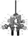
图1、一个实施例中操纵手柄结构示意图;Fig. 1 is a schematic diagram of the structure of a joystick in one embodiment;
图2、一个实施例中操纵手柄伺服系统结构示意图;Fig. 2 is a schematic diagram of the structure of a joystick servo system in one embodiment;
图3、一个实施例中斜坡信号下的控制效果示意图;FIG3 is a schematic diagram of a control effect under a ramp signal in one embodiment;
图4、一个实施例中外力干扰估计值示意图;FIG4 is a schematic diagram of an external force interference estimation value in one embodiment;
图5、一个实施例中系统参数a1估计值示意图;FIG5 is a schematic diagram of an estimated value of a system parametera1 in one embodiment;
图中:1-操纵杆、2-安装螺栓、3-连接蹄形、4-Y轴连接键、5-弹簧垫片、6-Y左半轴、7-轴承、8-第二齿轮对、9-第二电机、10-操纵叉、11-连接螺母、12-Y右半轴、13-X轴连接键、14-X轴、15-第一齿轮对、16-第一电机。In the figure: 1-joystick, 2-mounting bolt, 3-connecting shoe, 4-Y-axis connecting key, 5-spring washer, 6-Y left half shaft, 7-bearing, 8-second gear pair, 9-second motor, 10-control fork, 11-connecting nut, 12-Y right half shaft, 13-X-axis connecting key, 14-X-axis, 15-first gear pair, 16-first motor.
具体实施方式DETAILED DESCRIPTION
下面将结合本申请实施例中的附图,对本申请实施例中的技术方案进行清楚、完整地描述,显然,所描述的实施例仅仅是本申请一部分实施例,而不是全部的实施例。The technical solutions in the embodiments of the present application will be clearly and completely described below in conjunction with the drawings in the embodiments of the present application. Obviously, the described embodiments are only part of the embodiments of the present application, rather than all the embodiments.
在一个实施例中,将二自由度操纵手柄作为触觉再现操控终端,两个并排布置的伺服电机作为驱动单元,通过空间垂直交错排列的锥齿轮传动,来实现电机到手柄末端的运动和力的传递。In one embodiment, a two-degree-of-freedom joystick is used as a tactile reproduction control terminal, and two servo motors arranged side by side are used as drive units, which realize the transmission of movement and force from the motor to the end of the handle through bevel gears arranged vertically and staggered in space.
图1为一个二自由度操纵手柄,包括操纵杆(1)、安装螺栓(2)、操纵叉(10)、连接蹄形(3)、Y轴连接键(4)、弹簧垫片(5)、Y左半轴(6)、轴承(7)、第二齿轮对(8)、第二电机(9)、连接螺母(11)、Y右半轴(12)、X轴连接键(13)、X轴(14)、第一齿轮对(15)、第一电机(16)。其中:FIG1 is a two-degree-of-freedom joystick, comprising a joystick (1), mounting bolts (2), a joystick fork (10), a connecting shoe (3), a Y-axis connecting key (4), a spring washer (5), a Y-left half-shaft (6), a bearing (7), a second gear pair (8), a second motor (9), a connecting nut (11), a Y-right half-shaft (12), an X-axis connecting key (13), an X-axis (14), a first gear pair (15), and a first motor (16). Among them:
操作杆一端通过安装螺栓与操纵叉固定,另一端穿过连接蹄形中间的口。操纵叉通过安装销固定在X轴上。Y轴包括Y左半轴和Y右半轴,通过连接螺母与连接蹄形的两端相连,在半轴和连接蹄形之间有弹簧垫片。X轴、Y轴通过轴承实现动态配合,通过轴承端盖实现各自所在轴的轴向定位。固定好的操作手柄在其与X轴确定的平面内能够独立于Y轴旋转。而在连接蹄形开口中,操作杆能够在保持X轴状态不变的情况下,带动连接蹄形转动,从而带动Y轴绕自身轴心线转动,也能利用开口在不带动连接蹄形转动的情况下,通过操纵叉带动X轴绕自身轴心线转动。即:操作手柄在X轴方向和Y轴方向的运动都是相互独立的,不需要解耦。One end of the operating rod is fixed to the operating fork by a mounting bolt, and the other end passes through the opening in the middle of the connecting shoe. The operating fork is fixed to the X-axis by a mounting pin. The Y-axis includes a left half-axis and a right half-axis of Y, which are connected to the two ends of the connecting shoe through a connecting nut, and there is a spring gasket between the half-axis and the connecting shoe. The X-axis and the Y-axis are dynamically matched through bearings, and the axial positioning of each axis is achieved through the bearing end cover. The fixed operating handle can rotate independently of the Y-axis in the plane determined by it and the X-axis. In the opening of the connecting shoe, the operating rod can drive the connecting shoe to rotate while keeping the X-axis state unchanged, thereby driving the Y-axis to rotate around its own axis. It can also use the opening to drive the X-axis to rotate around its own axis through the operating fork without driving the connecting shoe to rotate. That is: the movement of the operating handle in the X-axis direction and the Y-axis direction are independent of each other, and no decoupling is required.
第一齿轮对的一个齿轮通过X轴连接键固定在X轴的一端,第二齿轮对的一个齿轮通过Y轴连接键固定在Y轴的一端。每个齿轮对的两个锥齿轮相互垂直传动连接。第一电机、第二电机提供驱动力,分别使两个齿轮对中位于传动端的齿轮转动,带动位于X轴或者Y轴的齿轮转动,从而使X轴或Y轴绕其自身轴心线旋转。One gear of the first gear pair is fixed to one end of the X-axis through the X-axis connecting key, and one gear of the second gear pair is fixed to one end of the Y-axis through the Y-axis connecting key. The two bevel gears of each gear pair are vertically connected to each other. The first motor and the second motor provide driving force to rotate the gears at the transmission end of the two gear pairs, respectively, and drive the gears at the X-axis or Y-axis to rotate, so that the X-axis or Y-axis rotates around its own axis.
上述操作手柄,采用直流电机伺服电机作为驱动机构,通过调整触觉操纵手柄控制器中直流伺服电机的占空比,控制伺服电机的实际角位移追踪期望角位移。电机的实际角位移传至操纵手柄末端,使末端手柄产生特定运动,进而实现触觉再现。The above-mentioned operating handle uses a DC motor servo motor as a driving mechanism. By adjusting the duty cycle of the DC servo motor in the tactile joystick controller, the actual angular displacement of the servo motor is controlled to track the desired angular displacement. The actual angular displacement of the motor is transmitted to the end of the joystick, causing the end handle to produce a specific movement, thereby realizing tactile reproduction.
具体地,采用下述步骤,实现操纵手柄触觉再现控制。步骤包括:Specifically, the following steps are adopted to realize the tactile reproduction control of the joystick. The steps include:
S1、建立操纵手柄动力传递机构的动力学模型:S1. Establish the dynamic model of the power transmission mechanism of the joystick:

其中,JT表示整个动力传输机构的转动惯量。整个动力传输机构如图1所示,具体包括第一电机的输出轴、第一齿轮对、操纵杆、第二电机的输出轴、第二齿轮对、连接蹄形、Y左右半轴、左右连接螺母、左右弹簧垫片以及左右轴承内圈、左右操纵叉、操纵杆以及左右安装螺栓。这些组件的转动惯量都是可以根据相应的质量计算得到的。αm表示电机输出的角加速度,一般是未知的;cT为动力传递机构的阻尼,一般是未知的。ωm表示电机的输出的角速度,TTf为干扰项,表示传递机构的内部摩擦和未知外部干扰,这里的系统内部摩擦可通过斯特里贝克摩擦模型进行辨识。Tout表示经由传递机构到达操纵手柄末端的扭矩,ηT表示操纵手柄的传输效率,iT表示齿轮的传动比。θm表示电机输出的角位移。θout表示传至触觉操纵手柄末端的角位移。Wherein, JT represents the moment of inertia of the entire power transmission mechanism. The entire power transmission mechanism is shown in FIG1 , and specifically includes the output shaft of the first motor, the first gear pair, the joystick, the output shaft of the second motor, the second gear pair, the connecting shoe, the left and right half shafts of Y, the left and right connecting nuts, the left and right spring washers, the left and right inner rings of the bearings, the left and right joysticks, the joystick, and the left and right mounting bolts. The moment of inertia of these components can be calculated based on the corresponding mass. αm represents the angular acceleration output by the motor, which is generally unknown; cT is the damping of the power transmission mechanism, which is generally unknown. ωm represents the angular velocity of the output of the motor, TTf is the interference term, which represents the internal friction of the transmission mechanism and the unknown external interference. The internal friction of the system here can be identified by the Stribeck friction model. Tout represents the torque reaching the end of the joystick through the transmission mechanism, ηT represents the transmission efficiency of the joystick, and iT represents the gear ratio. θm represents the angular displacement output by the motor. θout represents the angular displacement transmitted to the end of the tactile joystick.
S2、基于电压方程和运动方程,建立直流伺服电机的动力学模型:S2. Based on the voltage equation and motion equation, establish the dynamic model of the DC servo motor:

其中,u表示占空比,作为电机控制的输入。V表示电机电压,La表示电枢电感,ia表示流经电枢的电流,
以一个电机的运动状态为例说明控制器的构建过程,结合式(1)和式(2)可得直流电机伺服系统的转矩平衡式:Taking the motion state of a motor as an example to illustrate the controller construction process, the torque balance equation of the DC motor servo system can be obtained by combining equations (1) and (2):

为了便于控制器的设计,以操纵手柄的一个自由度的操纵为例,将上述伺服电机动力学模型和操纵手柄动力学模型结合,选取电机输出转角θm、输出转速ωm、电枢电流ia为系统的状态变量,那么触觉操纵手柄的状态方程可表示为:In order to facilitate the design of the controller, taking the manipulation of one degree of freedom of the joystick as an example, the above servo motor dynamics model and the joystick dynamics model are combined, and the motor output angle θm , output speed ωm , and armature currentia are selected as the state variables of the system. Then the state equation of the tactile joystick can be expressed as:

对于操作手柄而言,
在双边遥操纵系统中,提高系统透明度是很重要的一项内容,当透明度足够高的时候,操纵员会感受到无质量和无限僵硬的操作,并体验到操纵远程的直接感觉。现有的遥操纵框架中大都配备有力传感器,为了克服其存在带来的弊端,在实施时,将末端执行器所受到的人手外力视为未知干扰力,并在控制器设计中加入对其的估计。In bilateral telecontrol systems, it is very important to improve the transparency of the system. When the transparency is high enough, the operator will feel the massless and infinitely stiff operation and experience the direct feeling of remote control. Most of the existing telecontrol frameworks are equipped with force sensors. In order to overcome the disadvantages of their existence, the external force of the human hand on the end effector is regarded as an unknown interference force during implementation, and its estimation is included in the controller design.
为简化推导过程中繁杂的物理符号,令:In order to simplify the complicated physical symbols in the derivation process, let:


注意:上述系数赋值只是为了在说明书撰写过程中文字表达得更加简洁,没有实际的物理含义,在相关技术人员应用此技术进行实际的实施过程中,可以选择不做此赋值。Note: The above coefficient assignment is only for the purpose of making the text more concise during the specification writing process and has no actual physical meaning. When relevant technical personnel apply this technology for actual implementation, they may choose not to make this assignment.
其中din表示系统中已知干扰项,dout表示系统的未知干扰项,在这个操纵手柄系统中,这个未知干扰力就表示外界的人手操纵力,触觉操纵手柄系统状态方程(4)重新改写为:Where din represents the known interference term in the system, and dout represents the unknown interference term in the system. In this joystick system, the unknown interference force represents the external manual manipulation force. The state equation (4) of the tactile joystick system is rewritten as:

S3、触觉操纵手柄系统设计的目的是给定伺服电机的期望角位移θd,设计输入占空比u,让伺服电机的实际角位移θm去追踪期望角位移θd。然后电机的角位移传至操纵手柄末端,以实现末端手柄的特定运动,人手与操纵手柄的接触过程中,产生对人手的“拖曳”,由此实现触觉的再现。本发明所述系统中,动力传输机构的阻尼cT是未知的,干扰力dout是未知但有界的,也就是(5)式中的a1和dout。S3. The purpose of the tactile joystick system design is to design the input duty cycle u given the desired angular displacement θd of the servo motor, so that the actual angular displacement θm of the servo motor can track the desired angular displacement θd . Then the angular displacement of the motor is transmitted to the end of the joystick to achieve the specific movement of the end handle. During the contact between the human hand and the joystick, the human hand is "dragged", thereby achieving the reproduction of tactile sensation. In the system described in the present invention, the damping cT of the power transmission mechanism is unknown, and the interference force dout is unknown but bounded, that is, a1 and dout in formula (5).
换句话说,这个操纵系统是未知系统,采用传统的控制方法是无法对未知系统进行精确控制的。此外,在一般的触觉操纵手柄中,是有在操纵手柄末端加入力/转矩传感器进行人手干扰力的测量的,但是,力传感器的引入需要系统额外的接线,这必将导致整个系统变得庞大且昂贵,这也是本发明的主要出发点之一,也就是实现轻量化、高性价比的触觉操纵手柄控制器的设计,因此在本实施方式中遵循反步法的步骤,从数学的角度,也就是李雅普诺夫意义下的稳定,从而得出了系统所有参数的更新律,从而得到系统的控制输入,也就是伺服电机的占空比u,当然,具体到本实施方式的应用场景,只需要在参数更新律中提取出a1和dout即可,但是,从事本发明所述领域的相关技术人员,也可以将本文得到的控制规律推广到其他系统,因为在具体技术方案介绍中,也得到了系统的其他参数的更新律。接下来具体介绍控制规律的推导过程,其主要原理就是保证上文所述的系统3个状态变量在李雅普诺夫意义下的渐进稳定:In other words, this control system is an unknown system, and it is impossible to accurately control the unknown system using traditional control methods. In addition, in general tactile control handles, a force/torque sensor is added to the end of the control handle to measure the interference force of the human hand. However, the introduction of the force sensor requires additional wiring of the system, which will inevitably cause the entire system to become large and expensive. This is also one of the main starting points of the present invention, that is, to achieve the design of a lightweight and cost-effective tactile control handle controller. Therefore, in this embodiment, the steps of the backstepping method are followed. From a mathematical point of view, that is, stability in the sense of Lyapunov, the update law of all system parameters is obtained, thereby obtaining the control input of the system, that is, the duty cycle u of the servo motor. Of course, specifically to the application scenario of this embodiment, it is only necessary to extracta1 anddout from the parameter update law. However, relevant technical personnel engaged in the field described in the present invention can also generalize the control law obtained in this article to other systems, because in the introduction of the specific technical solution, the update law of other parameters of the system is also obtained. Next, the derivation process of the control law is specifically introduced. Its main principle is to ensure the asymptotic stability of the three state variables of the system mentioned above in the sense of Lyapunov:
S31、首先,引入两个误差变量:S31. First, two error variables are introduced:

其中,θd表示期望角位移,e1表示系统第一个状态变量角位移的动态误差,e2表示系统第二个状态变量角速度的动态误差,根据反步法思想,为保证角速度动态误差足够小,Δ1是需要设计的第一个虚拟控制量。Among them,θd represents the desired angular displacement,e1 represents the dynamic error of the angular displacement of the first state variable of the system, ande2 represents the dynamic error of the angular velocity of the second state variable of the system. According to the idea of backstepping, in order to ensure that the dynamic error of the angular velocity is small enough,Δ1 is the first virtual control variable that needs to be designed.
为了保证李雅普诺夫意义下的稳定,这里设计,注意,这里略去了数学上的理论推导过程,给出的控制量是能保证系统稳定下,系统状态变量误差最小:In order to ensure the stability in the sense of Lyapunov, the design here is omitted. The control quantity given is to ensure the stability of the system and the minimum error of the system state variable:

其中,δ1是第一虚拟控制变量中的角位移误差项系数,在实际应用中取任意正常数即可。
S32、引入第三个误差变量:S32, introduce the third error variable:
e3=ia-Δ2 (8)e3 = ia - Δ2 (8)
其中,e3表示系统第三个状态变量电枢电流的动态误差。Δ2是为保证电枢电流误差足够小,设计的第二个虚拟控制量。Among them, e3 represents the dynamic error of the third state variable of the system, the armature current. Δ2 is the second virtual control variable designed to ensure that the armature current error is small enough.

其中,


为保证李亚普诺普意义下的稳定性,这里得到上述估计值的更新规律:To ensure stability in the Lyapunov sense, the update rule of the above estimates is obtained here:

这里涉及到系统参数更新估计中的三个初值,即b10、a10和D10,其具体的数值是需要根据所应用的实际系统进行计算确定的,一般为非负常数,这里不作为本发明的内容,不做过多阐述。Here, three initial values in the system parameter update estimation are involved, namely b10 , a10 and D10 , whose specific values need to be calculated and determined according to the actual system used, and are generally non-negative constants. They are not included in the content of the present invention and will not be elaborated on in detail.
S33、反步法最后推导到系统的输入部分,也就是电机的占空比变化规律,这个控制器输入变化规律是本发明的核心内容:S33, the backstepping method finally derives the input part of the system, that is, the duty cycle variation law of the motor. This controller input variation law is the core content of the present invention:


其中,


其中:αm表示电机输出的角加速度。Where: αm represents the angular acceleration output by the motor.
到此,在已知期望轨迹与已知干扰力的情况下,对含有未知系统参数的触觉操纵系统输入量计算已交待完毕。At this point, the calculation of the input quantity of the tactile manipulation system with unknown system parameters has been completed, given the known expected trajectory and the known interference force.
S34、在计算最终控制器的输入过程中,同样为了保证系统稳定性,衍生了系统剩余参数的更新规律:S34. In the process of calculating the input of the final controller, in order to ensure the stability of the system, the update rules of the remaining system parameters are derived:

其中,参数更新律中设定的一系列系数,包括η1、η2、η3、η4、η5、η6、η7、η8、λ1、λ2、λ3、λ4、λ5、λ6、λ7、λ8,在实际应用中都可以取任意的正常数,不会影响系统的稳定性与精度的。同样,这里涉及到系统剩余的参数初值,包括b20为b2估计值初值,b30为b3估计值初值,a110为a1第二估计值初值,D20为D的第二个估计值初值,D为的上限值,b20、b30、a110、a20、D20是根据实际情况确定,一般是非负常数。Among them, a series of coefficients set in the parameter update law, including η1 , η2 , η3 , η4 , η5 , η6 , η7 , η8, λ1 , λ2 , λ3 ,
在实验中,将上述所建模型以及控制器加于操纵手柄伺服系统上,设计追踪曲线为斜坡函数:In the experiment, the above-mentioned model and controller are added to the joystick servo system, and the tracking curve is designed as a ramp function:

追踪效果如图3所示。此外,系统参数以及未知干扰也都是有界的,如图4和图5所示,足以证明本发明所构建控制方法的有效性和精确性。The tracking effect is shown in Figure 3. In addition, the system parameters and unknown disturbances are also bounded, as shown in Figures 4 and 5, which is sufficient to prove the effectiveness and accuracy of the control method constructed by the present invention.
通过以上的实施方式的描述,所属领域的技术人员可以清楚地了解到本公开可借助软件加必需的通用硬件的方式来实现,当然也可以通过专用硬件包括专用集成电路、专用CPU、专用存储器、专用元器件等来实现。一般情况下,凡由计算机程序完成的功能都可以很容易地用相应的硬件来实现,而且,用来实现同一功能的具体硬件结构也可以是多种多样的,例如模拟电路、数字电路或专用电路等。但是,对本公开而言更多情况下,软件程序实现是更佳的实施方式。Through the description of the above implementation modes, those skilled in the art can clearly understand that the present disclosure can be implemented by means of software plus necessary general hardware, and of course can also be implemented by special hardware including special integrated circuits, special CPUs, special memories, special components, etc. In general, all functions performed by computer programs can be easily implemented by corresponding hardware, and the specific hardware structures used to implement the same function can also be various, such as analog circuits, digital circuits or special circuits, etc. However, for the present disclosure, software program implementation is a better implementation mode in most cases.
在上述实施方式中,人手操纵力相当于外界干扰力,通过在控制器设计中加入了对它的估计,少去了外加传感器,降低了成本,同时也降低了因传感器导致的系统复杂度增高的问题。In the above implementation, the manual operating force is equivalent to the external interference force. By incorporating its estimation into the controller design, the external sensor is eliminated, the cost is reduced, and the problem of increased system complexity caused by the sensor is also reduced.
综上,针对无传感器觉操纵手柄触觉再现控制方法,本发明提出了一种基于反步法的自适应控制器,将手柄末端的人手力视为未知干扰加入至系统模型中,并设计了参数更新律,实现了在含未知参数系统模型下的精确控制。并且在李雅普诺夫意义下,其可以证实具有稳定性。数值实验结果显示,所提控制方法具有很好的跟踪效果,计算得出的输入控制信号也都是合理的,整个闭环系统的参数估计值都是有界且收敛的。本发明所述的方法也可以拓宽应用至其余伺服电机系统或者子系统中,该类系统有一个共同特点,即系统模型中含有未知参数和未知扰动,应用本发明提出的方法,均可收到很好的控制效果。In summary, for the tactile reproduction control method of the sensorless joystick, the present invention proposes an adaptive controller based on the backstepping method, which regards the human hand force at the end of the handle as an unknown disturbance and adds it to the system model, and designs a parameter update law to achieve precise control under the system model containing unknown parameters. And in the sense of Lyapunov, it can be proved to be stable. The results of numerical experiments show that the proposed control method has a good tracking effect, the calculated input control signals are also reasonable, and the parameter estimates of the entire closed-loop system are bounded and convergent. The method described in the present invention can also be extended to other servo motor systems or subsystems. Such systems have a common feature, that is, the system model contains unknown parameters and unknown disturbances. The method proposed in the present invention can achieve good control effects.
尽管以上结合附图对本发明的实施方案进行了描述,但本发明并不局限于上述的具体实施方案和应用领域,上述的具体实施方案仅仅是示意性的、指导性的,而不是限制性的。本领域的普通技术人员在本说明书的启示下和在不脱离本发明权利要求所保护的范围的情况下,还可以做出很多种的形式,这些均属于本发明保护之列。Although the embodiments of the present invention are described above in conjunction with the accompanying drawings, the present invention is not limited to the above specific embodiments and application fields, and the above specific embodiments are only illustrative and instructive, rather than restrictive. A person of ordinary skill in the art can also make many forms under the guidance of this specification and without departing from the scope of protection of the claims of the present invention, all of which belong to the protection of the present invention.
Claims (10)


Priority Applications (1)
| Application Number | Priority Date | Filing Date | Title |
|---|---|---|---|
| CN202211408873.7ACN115903997B (en) | 2022-11-10 | 2022-11-10 | A tactile reproduction control method for a joystick without an external force sensor |
Applications Claiming Priority (1)
| Application Number | Priority Date | Filing Date | Title |
|---|---|---|---|
| CN202211408873.7ACN115903997B (en) | 2022-11-10 | 2022-11-10 | A tactile reproduction control method for a joystick without an external force sensor |
Publications (2)
| Publication Number | Publication Date |
|---|---|
| CN115903997Atrue CN115903997A (en) | 2023-04-04 |
| CN115903997B CN115903997B (en) | 2024-05-10 |
Family
ID=86481819
Family Applications (1)
| Application Number | Title | Priority Date | Filing Date |
|---|---|---|---|
| CN202211408873.7AActiveCN115903997B (en) | 2022-11-10 | 2022-11-10 | A tactile reproduction control method for a joystick without an external force sensor |
Country Status (1)
| Country | Link |
|---|---|
| CN (1) | CN115903997B (en) |
Citations (9)
| Publication number | Priority date | Publication date | Assignee | Title |
|---|---|---|---|---|
| US5374884A (en)* | 1992-11-18 | 1994-12-20 | University Of Michigan, The Board Of Regents Acting . . . | Model-based position-repeatable disturbance compensation |
| US20060238153A1 (en)* | 2003-06-11 | 2006-10-26 | Webster Craig D | Handwheel-operated device |
| CN201149485Y (en)* | 2007-10-23 | 2008-11-12 | 冯黎 | Electronic hand wheel of three coordinate measuring linotype machine |
| CN102980766A (en)* | 2012-12-24 | 2013-03-20 | 重庆理工大学 | Measuring and test method of dynamic transmission efficiency of AMT gear selecting actuator |
| CN103733158A (en)* | 2011-07-26 | 2014-04-16 | 大陆汽车有限责任公司 | Operating device |
| CN105116961A (en)* | 2015-07-21 | 2015-12-02 | 东南大学 | Intelligent force feedback handle and control method thereof |
| CN207623831U (en)* | 2018-01-09 | 2018-07-17 | 黄羽婵 | Combination stove knob |
| CN210401593U (en)* | 2019-07-02 | 2020-04-24 | 艾司匹技电机(苏州)有限公司 | Motor load testing mechanism |
| CN113012516A (en)* | 2021-03-11 | 2021-06-22 | 东南大学 | Three-freedom-degree force feedback handle comprising two vertically staggered shafts |
- 2022
- 2022-11-10CNCN202211408873.7Apatent/CN115903997B/enactiveActive
Patent Citations (9)
| Publication number | Priority date | Publication date | Assignee | Title |
|---|---|---|---|---|
| US5374884A (en)* | 1992-11-18 | 1994-12-20 | University Of Michigan, The Board Of Regents Acting . . . | Model-based position-repeatable disturbance compensation |
| US20060238153A1 (en)* | 2003-06-11 | 2006-10-26 | Webster Craig D | Handwheel-operated device |
| CN201149485Y (en)* | 2007-10-23 | 2008-11-12 | 冯黎 | Electronic hand wheel of three coordinate measuring linotype machine |
| CN103733158A (en)* | 2011-07-26 | 2014-04-16 | 大陆汽车有限责任公司 | Operating device |
| CN102980766A (en)* | 2012-12-24 | 2013-03-20 | 重庆理工大学 | Measuring and test method of dynamic transmission efficiency of AMT gear selecting actuator |
| CN105116961A (en)* | 2015-07-21 | 2015-12-02 | 东南大学 | Intelligent force feedback handle and control method thereof |
| CN207623831U (en)* | 2018-01-09 | 2018-07-17 | 黄羽婵 | Combination stove knob |
| CN210401593U (en)* | 2019-07-02 | 2020-04-24 | 艾司匹技电机(苏州)有限公司 | Motor load testing mechanism |
| CN113012516A (en)* | 2021-03-11 | 2021-06-22 | 东南大学 | Three-freedom-degree force feedback handle comprising two vertically staggered shafts |
Also Published As
| Publication number | Publication date |
|---|---|
| CN115903997B (en) | 2024-05-10 |
Similar Documents
| Publication | Publication Date | Title |
|---|---|---|
| Tseng et al. | Fuzzy tracking control design for nonlinear dynamic systems via TS fuzzy model | |
| Keighobadi et al. | From nonlinear to fuzzy approaches in trajectory tracking control of wheeled mobile robots | |
| CN110181510B (en) | Mechanical arm trajectory tracking control method based on time delay estimation and fuzzy logic | |
| CN106094530B (en) | The Design of non-linear controllers method of inverted pendulum | |
| CN110077456A (en) | Steering control device | |
| CN109227545B (en) | A target tracking control method for flexible manipulators based on reachable set estimation | |
| CN104908814B (en) | A fractional-order PID control method for automobile steering-by-wire system | |
| Peng et al. | Adaptive fuzzy integral terminal sliding mode control of a nonholonomic wheeled mobile robot | |
| Yang et al. | Neural network dynamic surface position control of n‐joint robot driven by PMSM with unknown load observer | |
| CN107132761A (en) | A kind of electric steering engine design method using pure fuzzy and fuzzy complex controll | |
| CN106681154B (en) | The electric vehicle self-adapting control method being saturated for uncertain mass center and Unknown worm | |
| Mohamed | Decoupled third-order fuzzy sliding model control for cart-inverted pendulum system | |
| CN114035436B (en) | A backstepping control method, storage medium and device based on saturation adaptive law | |
| CN117506896A (en) | Control method for single-connecting-rod mechanical arm embedded with direct-current motor | |
| CN104678763B (en) | Friction compensation and dynamic surface control method based on least squares support vector machine for electromechanical servo system | |
| Niu et al. | Global asymptotic nonlinear PID control with a new generalized saturation function | |
| CN118456431A (en) | A fixed-time control method for a robotic arm with preset performance constraints | |
| CN115903997B (en) | A tactile reproduction control method for a joystick without an external force sensor | |
| CN108931922A (en) | A kind of adaptive Non-smooth surface Trajectory Tracking Control method of industrial robot | |
| CN112147894A (en) | Active control method of wheeled mobile robot based on kinematics and dynamics model | |
| CN117590754B (en) | Intelligent learning output regulation and control method of robot system | |
| CN107263455B (en) | The Position Tracking Control method of two degrees of freedom SCARA robot | |
| Noor et al. | STUDY THE PERFORMANCE OF TWO-WHEELED BALANCING MOBILE ROBOT USING FUZZY PD CONTROLLER | |
| CN118219267A (en) | Flexible joint mechanical arm track tracking control algorithm | |
| CN117283562A (en) | Flexible mechanical arm control method based on preset time stabilization and high-order sliding mode algorithm |
Legal Events
| Date | Code | Title | Description |
|---|---|---|---|
| PB01 | Publication | ||
| PB01 | Publication | ||
| SE01 | Entry into force of request for substantive examination | ||
| SE01 | Entry into force of request for substantive examination | ||
| GR01 | Patent grant | ||
| GR01 | Patent grant |