CN115903185A - Optical imaging system - Google Patents
Optical imaging systemDownload PDFInfo
- Publication number
- CN115903185A CN115903185ACN202211664215.4ACN202211664215ACN115903185ACN 115903185 ACN115903185 ACN 115903185ACN 202211664215 ACN202211664215 ACN 202211664215ACN 115903185 ACN115903185 ACN 115903185A
- Authority
- CN
- China
- Prior art keywords
- lens
- imaging system
- optical imaging
- refractive power
- image
- Prior art date
- Legal status (The legal status is an assumption and is not a legal conclusion. Google has not performed a legal analysis and makes no representation as to the accuracy of the status listed.)
- Pending
Links
Images


Classifications
- G—PHYSICS
- G02—OPTICS
- G02B—OPTICAL ELEMENTS, SYSTEMS OR APPARATUS
- G02B27/00—Optical systems or apparatus not provided for by any of the groups G02B1/00 - G02B26/00, G02B30/00
- G02B27/0025—Optical systems or apparatus not provided for by any of the groups G02B1/00 - G02B26/00, G02B30/00 for optical correction, e.g. distorsion, aberration
- G—PHYSICS
- G02—OPTICS
- G02B—OPTICAL ELEMENTS, SYSTEMS OR APPARATUS
- G02B9/00—Optical objectives characterised both by the number of the components and their arrangements according to their sign, i.e. + or -
- G02B9/64—Optical objectives characterised both by the number of the components and their arrangements according to their sign, i.e. + or - having more than six components
- G—PHYSICS
- G02—OPTICS
- G02B—OPTICAL ELEMENTS, SYSTEMS OR APPARATUS
- G02B13/00—Optical objectives specially designed for the purposes specified below
- G02B13/001—Miniaturised objectives for electronic devices, e.g. portable telephones, webcams, PDAs, small digital cameras
- G02B13/0015—Miniaturised objectives for electronic devices, e.g. portable telephones, webcams, PDAs, small digital cameras characterised by the lens design
- G02B13/002—Miniaturised objectives for electronic devices, e.g. portable telephones, webcams, PDAs, small digital cameras characterised by the lens design having at least one aspherical surface
- G02B13/0045—Miniaturised objectives for electronic devices, e.g. portable telephones, webcams, PDAs, small digital cameras characterised by the lens design having at least one aspherical surface having five or more lenses
- G—PHYSICS
- G02—OPTICS
- G02B—OPTICAL ELEMENTS, SYSTEMS OR APPARATUS
- G02B13/00—Optical objectives specially designed for the purposes specified below
- G02B13/18—Optical objectives specially designed for the purposes specified below with lenses having one or more non-spherical faces, e.g. for reducing geometrical aberration
- G—PHYSICS
- G02—OPTICS
- G02B—OPTICAL ELEMENTS, SYSTEMS OR APPARATUS
- G02B5/00—Optical elements other than lenses
- G02B5/005—Diaphragms
- H—ELECTRICITY
- H04—ELECTRIC COMMUNICATION TECHNIQUE
- H04N—PICTORIAL COMMUNICATION, e.g. TELEVISION
- H04N23/00—Cameras or camera modules comprising electronic image sensors; Control thereof
- H04N23/50—Constructional details
- H04N23/55—Optical parts specially adapted for electronic image sensors; Mounting thereof
Landscapes
- Physics & Mathematics (AREA)
- General Physics & Mathematics (AREA)
- Optics & Photonics (AREA)
- Engineering & Computer Science (AREA)
- Multimedia (AREA)
- Signal Processing (AREA)
- Lenses (AREA)
Abstract
Translated fromChinese
Description
Translated fromChinese相关申请的交叉引用CROSS-REFERENCE TO RELATED APPLICATIONS
本申请要求于2018年5月29日在韩国知识产权局提交的第10-2018-0061394号韩国专利申请以及于2018年9月5日在韩国知识产权局提交的第10-2018-0106186号韩国专利申请的优先权的权益,该韩国专利申请的全部公开内容出于所有目的而通过引用并入本申请中。This application claims the benefit of priority from Korean Patent Application No. 10-2018-0061394 filed on May 29, 2018, in the Korean Intellectual Property Office, and Korean Patent Application No. 10-2018-0106186 filed on September 5, 2018, in the Korean Intellectual Property Office, the disclosures of which are incorporated herein in their entirety for all purposes by reference.
技术领域Technical Field
本申请涉及包括七片透镜的光学成像系统。The present application relates to an optical imaging system including seven lenses.
背景技术Background Art
移动终端通常设置有用于视频通信或拍摄图像的相机。然而,由于移动终端内部的空间限制,难以在这种用于移动终端的相机中实现高性能。Mobile terminals are generally provided with cameras for video communication or capturing images. However, due to space limitations inside the mobile terminal, it is difficult to achieve high performance in such cameras for mobile terminals.
因此,随着设置有相机的移动终端的数量增加,对能够在不增加相机尺寸的情况下改善相机性能的光学成像系统的需求已增加。Therefore, as the number of mobile terminals provided with cameras increases, the demand for an optical imaging system capable of improving camera performance without increasing the size of the camera has increased.
发明内容Summary of the invention
提供本发明内容是为了以简化形式介绍构思的选择,这些构思将在下文具体实施方式中进一步描述。本发明内容不旨在表明所要求保护的主题的关键特征或必要特征,也不旨在用于帮助确定所要求保护的主题的范围。This Summary is provided to introduce a selection of concepts in a simplified form that are further described below in the Detailed Description. This Summary is not intended to identify key features or essential features of the claimed subject matter, nor is it intended to be used as an aid in determining the scope of the claimed subject matter.
在一个总体方面,光学成像系统包括从光学成像系统的物侧朝向光学成像系统的像侧按数字顺序依次布置的第一透镜、第二透镜、第三透镜、第四透镜、第五透镜、第六透镜和第七透镜,其中,光学成像系统满足1<|f123457-f|/f,其中,f123457为当第六透镜的折射率限定为与空气的折射率相等的1.0时第一透镜至第七透镜的组合焦距,f为光学成像系统的总焦距,且f123457和f以相同的测量单位表示。In one general aspect, an optical imaging system includes a first lens, a second lens, a third lens, a fourth lens, a fifth lens, a sixth lens, and a seventh lens arranged in numerical order from an object side of the optical imaging system toward an image side of the optical imaging system, wherein the optical imaging system satisfies 1<|f123457-f|/f, wherein f123457 is a combined focal length of the first to seventh lenses when a refractive index of the sixth lens is limited to 1.0 which is equal to a refractive index of air, f is a total focal length of the optical imaging system, and f123457 and f are expressed in the same measurement unit.
第一透镜的物侧面可为凸。The object-side surface of the first lens may be convex.
第七透镜的像侧面可为凹。The image-side surface of the seventh lens may be concave.
可以在第六透镜的物侧面和像侧面中的任一个面或两个面上形成至少一个反曲点。At least one inflection point may be formed on either one or both of the object-side surface and the image-side surface of the sixth lens.
可以在第七透镜的物侧面和像侧面中的任一个面或两个面上形成至少一个反曲点。At least one inflection point may be formed on either one or both of the object-side surface and the image-side surface of the seventh lens.
从第一透镜的物侧面到光学成像系统的成像面的距离可以是6mm或更小。The distance from the object-side surface of the first lens to the imaging surface of the optical imaging system may be 6 mm or less.
第二透镜的物侧面可为凸。The object-side surface of the second lens may be convex.
第三透镜的物侧面可为凸。The object-side surface of the third lens may be convex.
第四透镜的物侧面可为凸。The object-side surface of the fourth lens element may be convex.
第五透镜的物侧面或像侧面可为凸。The object-side surface or the image-side surface of the fifth lens element may be convex.
第六透镜可具有正屈光力。The sixth lens may have positive refractive power.
第七透镜可具有负屈光力。The seventh lens may have negative refractive power.
光学成像系统还可满足0.1<L1w/L7w<0.3,其中,L1w为第一透镜的重量,L7w为第七透镜的重量,且L1w和L7w以相同的测量单位表示。The optical imaging system may also satisfy 0.1<L1w/L7w<0.3, wherein L1w is the weight of the first lens, L7w is the weight of the seventh lens, and L1w and L7w are expressed in the same measurement unit.
光学成像系统还可包括设置在第六透镜与第七透镜之间的隔圈,光学成像系统还可满足0.5<S6d/f<1.2,其中,f为光学成像系统的总焦距,S6d为隔圈的内径,且S6d和f以相同的测量单位表示。The optical imaging system may further include a spacer ring arranged between the sixth lens and the seventh lens, and the optical imaging system may further satisfy 0.5<S6d/f<1.2, wherein f is the total focal length of the optical imaging system, S6d is the inner diameter of the spacer ring, and S6d and f are expressed in the same measurement unit.
光学成像系统还可满足0.4<L1TR/L7TR<0.7,其中,L1TR为第一透镜的总外径,L7TR为第七透镜的总外径,且L1TR和L7TR以相同的测量单位表示。The optical imaging system may also satisfy 0.4<L1TR/L7TR<0.7, wherein L1TR is a total outer diameter of the first lens, L7TR is a total outer diameter of the seventh lens, and L1TR and L7TR are expressed in the same measurement unit.
光学成像系统还可满足0.5<L1234TRavg/L7TR<0.75,其中,L1234TRavg为第一透镜至第四透镜的总外径的平均值,L7TR为第七透镜的总外径,且L1234TRavg和L7TR以相同的测量单位表示。The optical imaging system may also satisfy 0.5<L1234TRavg/L7TR<0.75, wherein L1234TRavg is an average value of the total outer diameters of the first to fourth lenses, L7TR is the total outer diameter of the seventh lens, and L1234TRavg and L7TR are expressed in the same measurement unit.
光学成像系统还可满足0.5<L12345TRavg/L7TR<0.76,其中,L12345TRavg为第一透镜至第五透镜的总外径的平均值,L7TR为第七透镜的总外径,且L12345TRavg和L7TR以相同的测量单位表示。The optical imaging system may also satisfy 0.5<L12345TRavg/L7TR<0.76, wherein L12345TRavg is the average value of the total outer diameters of the first to fifth lenses, L7TR is the total outer diameter of the seventh lens, and L12345TRavg and L7TR are expressed in the same measurement unit.
第二透镜可具有正屈光力。The second lens may have positive refractive power.
第三透镜可具有正屈光力。The third lens may have positive refractive power.
第七透镜的物侧面的近轴区域可为凹。A paraxial region of the object-side surface of the seventh lens element may be concave.
根据以下详细描述、附图和所附权利要求,其它特征和方面将是显而易见的。Other features and aspects will be apparent from the following detailed description, the accompanying drawings, and the appended claims.
附图说明BRIEF DESCRIPTION OF THE DRAWINGS
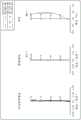
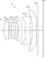
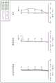
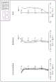
图1是示出光学成像系统的第一示例的视图。FIG. 1 is a view showing a first example of an optical imaging system.
图2示出了图1的光学成像系统的像差曲线。FIG. 2 shows aberration curves of the optical imaging system of FIG. 1 .
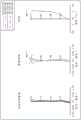
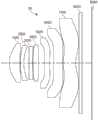
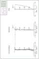
图3是示出光学成像系统的第二示例的视图。FIG. 3 is a view showing a second example of the optical imaging system.
图4示出了图3的光学成像系统的像差曲线。FIG. 4 shows aberration curves of the optical imaging system of FIG. 3 .
图5是示出光学成像系统的第三示例的视图。FIG. 5 is a view showing a third example of the optical imaging system.
图6示出了图5的光学成像系统的像差曲线。FIG. 6 shows aberration curves of the optical imaging system of FIG. 5 .
图7是示出光学成像系统的第四示例的视图。FIG. 7 is a view showing a fourth example of the optical imaging system.
图8示出了图7的光学成像系统的像差曲线。FIG. 8 shows aberration curves of the optical imaging system of FIG. 7 .
图9是示出光学成像系统的第五示例的视图。FIG. 9 is a view showing a fifth example of the optical imaging system.
图10示出了图9的光学成像系统的像差曲线。FIG. 10 shows aberration curves of the optical imaging system of FIG. 9 .
图11是示出光学成像系统的第六示例的视图。FIG. 11 is a view showing a sixth example of the optical imaging system.
图12示出了图11的光学成像系统的像差曲线。FIG. 12 shows aberration curves of the optical imaging system of FIG. 11 .
图13是示出光学成像系统的第七示例的视图。FIG. 13 is a view showing a seventh example of the optical imaging system.
图14示出了图13的光学成像系统的像差曲线。FIG. 14 shows aberration curves of the optical imaging system of FIG. 13 .
图15是示出光学成像系统的第八示例的视图。FIG. 15 is a view showing an eighth example of the optical imaging system.
图16示出了图15的光学成像系统的像差曲线。FIG. 16 shows aberration curves of the optical imaging system of FIG. 15 .
图17是示出光学成像系统的第九示例的视图。FIG. 17 is a view showing a ninth example of the optical imaging system.
图18示出了图17的光学成像系统的像差曲线。FIG. 18 shows aberration curves of the optical imaging system of FIG. 17 .
图19是示出光学成像系统的第十示例的视图。FIG. 19 is a view showing a tenth example of the optical imaging system.
图20示出了图19的光学成像系统的像差曲线。FIG. 20 shows aberration curves of the optical imaging system of FIG. 19 .
图21是示出光学成像系统的第十一示例的视图。FIG. 21 is a view showing an eleventh example of the optical imaging system.
图22示出了图21的光学成像系统的像差曲线。FIG. 22 shows aberration curves of the optical imaging system of FIG. 21 .
图23是示出光学成像系统的第十二示例的视图。FIG. 23 is a view showing a twelfth example of the optical imaging system.
图24示出了图23的光学成像系统的像差曲线。FIG. 24 shows aberration curves of the optical imaging system of FIG. 23 .
图25是示出光学成像系统的第十三示例的视图。FIG. 25 is a view showing a thirteenth example of the optical imaging system.
图26示出了图25的光学成像系统的像差曲线。FIG. 26 shows aberration curves of the optical imaging system of FIG. 25 .
图27是示出光学成像系统的第十四示例的视图。FIG. 27 is a view showing a fourteenth example of the optical imaging system.
图28示出了图27的光学成像系统的像差曲线。FIG. 28 shows aberration curves of the optical imaging system of FIG. 27 .
图29是示出光学成像系统的第十五示例的视图。FIG. 29 is a view showing a fifteenth example of the optical imaging system.
图30示出了图29的光学成像系统的像差曲线。FIG30 shows aberration curves of the optical imaging system of FIG29 .
图31是示出光学成像系统的第十六示例的视图。FIG. 31 is a view showing a sixteenth example of the optical imaging system.
图32示出了图31的光学成像系统的像差曲线。FIG32 shows aberration curves of the optical imaging system of FIG31 .
图33是示出光学成像系统的第十七示例的视图。FIG. 33 is a view showing a seventeenth example of the optical imaging system.
图34示出了图33的光学成像系统的像差曲线。FIG34 shows aberration curves of the optical imaging system of FIG33 .
图35是示出光学成像系统的第十八示例的视图。FIG35 is a view showing an eighteenth example of the optical imaging system.
图36示出了表示图35的像差特性的像差曲线。FIG. 36 shows aberration curves representing the aberration characteristics of FIG. 35 .
图37是示出光学成像系统的第十九示例的视图。FIG37 is a view showing a nineteenth example of the optical imaging system.
图38示出了图37的光学成像系统的像差曲线。FIG38 shows aberration curves of the optical imaging system of FIG37 .
图39是示出光学成像系统的第二十示例的视图。FIG39 is a view showing a twentieth example of the optical imaging system.
图40示出了图39的光学成像系统的像差曲线。FIG40 shows aberration curves of the optical imaging system of FIG39 .
图41是示出光学成像系统的第二十一示例的视图。FIG. 41 is a view showing a twenty-first example of the optical imaging system.
图42示出了图41的光学成像系统的像差曲线。FIG42 shows aberration curves of the optical imaging system of FIG41 .
图43是示出光学成像系统的第二十二示例的视图。FIG43 is a view showing a twenty-second example of the optical imaging system.
图44示出了图43的光学成像系统的像差曲线。FIG44 shows aberration curves of the optical imaging system of FIG43 .
图45是示出光学成像系统的第二十三示例的视图。FIG. 45 is a view showing a twenty-third example of the optical imaging system.
图46示出了图45的光学成像系统的像差曲线。FIG46 shows aberration curves of the optical imaging system of FIG45 .
图47和图48是示出彼此联接的光学成像系统和镜筒的示例的剖视图。47 and 48 are cross-sectional views illustrating examples of an optical imaging system and a lens barrel coupled to each other.
图49是示出第七透镜的示例的剖视图。FIG. 49 is a cross-sectional view illustrating an example of the seventh lens.
图50是示出透镜的肋的形状的示例的剖视图。FIG. 50 is a cross-sectional view showing an example of the shape of a rib of a lens.
在全部附图和整个详细描述中,相同的附图标记表示相同的元件。附图可能未按比例绘制,并且为了清楚、说明和方便,可能夸大了附图中的元件的相对尺寸、比例和描绘。Like reference numerals refer to like elements throughout the drawings and detailed description. The drawings may not be drawn to scale, and the relative size, proportions, and depiction of elements in the drawings may be exaggerated for clarity, illustration, and convenience.
具体实施方式DETAILED DESCRIPTION
提供以下详细描述以帮助读者获得对本申请中描述的方法、设备和/或系统的全面理解。然而,在理解本申请的公开内容之后,本申请中描述的方法、设备和/或系统的各种改变、修改和等同将是显而易见的。例如,本申请中描述的操作顺序仅仅是示例,并且除了必须以特定顺序发生的操作之外,不限于在本申请中所阐述的顺序,而可以在理解本申请的公开内容之后做出显而易见的改变。另外,为了更加清楚和简洁,可省略对本领域公知的特征的描述。The following detailed description is provided to help the reader obtain a comprehensive understanding of the method, device and/or system described in this application. However, after understanding the disclosure of this application, various changes, modifications and equivalences of the method, device and/or system described in this application will be apparent. For example, the order of operations described in this application is merely an example, and except for the operations that must occur in a specific order, it is not limited to the order set forth in this application, and obvious changes can be made after understanding the disclosure of this application. In addition, for greater clarity and brevity, the description of features well known in the art may be omitted.
本申请中描述的特征可以以不同的形式实施,并且不应被解释为限于本申请中描述的示例。更确切地,提供本申请中描述的示例仅仅是为了说明实现本申请中描述的方法、设备和/或系统的许多可行方式中的一些可行方式,在理解本申请的公开内容之后,这些可行方式将是显而易见的。The features described in this application may be implemented in different forms and should not be construed as being limited to the examples described in this application. Rather, the examples described in this application are provided only to illustrate some of the many possible ways to implement the methods, devices and/or systems described in this application, which will be apparent after understanding the disclosure of this application.
在说明书全文中,当诸如层、区域或基板的元件被称为在另一元件“上”、“连接至”或“联接至”另一元件时,该元件可直接在该另一元件“上”、直接“连接至”或直接“联接至”该另一元件,或者可存在介于其间的一项或多项其它中间元件。相反,当元件被称为“直接”在另一元件“上”、“直接连接至”或“直接联接至”另一元件时,可不存在介于其间的其它中间元件。Throughout the specification, when an element such as a layer, a region or a substrate is referred to as being “on”, “connected to” or “coupled to” another element, the element may be directly “on”, directly “connected to” or directly “coupled to” the other element, or one or more other intervening elements may be present. Conversely, when an element is referred to as being “directly” “on”, “directly connected to” or “directly coupled to” another element, there may be no other intervening elements.
如本申请中所使用的,措辞“和/或”包括相关列出项目中的任何两项或更多项中的任何一项和任何组合。As used in this application, the term "and/or" includes any one and any combination of any two or more of the associated listed items.
尽管诸如“第一”、“第二”、“第三”的措辞可在本申请中用于描述各种构件、组件、区域、层或区段,但是这些构件、组件、区域、层或区段不应受这些措辞的限制。更确切地,这些措辞仅用于将一个构件、组件、区域、层或区段与另一个构件、组件、区域、层或区段区分开。因此,在不背离示例的教导的情况下,本申请描述的示例中涉及的第一构件、第一组件、第一区域、第一层或第一区段还可被称为第二构件、第二组件、第二区域、第二层或第二区段。Although words such as "first", "second", and "third" may be used in the present application to describe various components, components, regions, layers, or sections, these components, components, regions, layers, or sections should not be limited by these words. More specifically, these words are only used to distinguish one component, component, region, layer, or section from another component, component, region, layer, or section. Therefore, without departing from the teachings of the examples, the first component, first component, first region, first layer, or first section involved in the examples described in the present application may also be referred to as the second component, second component, second region, second layer, or second section.
为了描述的方便,可在本申请中使用诸如“上方(above)”、“上部(upper)”、“下方(below)”和“下部(lower)”的空间相对措辞,以描述如附图中所示的一个元件相对于另一元件的关系。除了附图中所描绘的定向之外,空间相对措辞旨在涵盖装置在使用或操作中的不同定向。例如,如果图中的装置被翻转,则描述为相对于另一元件位于“上方(above)”或“上部(upper)”的元件将相对于该另一元件位于“下方(below)”或“下部(lower)”。因此,根据装置的空间定向,措辞“上方(above)”包括上方定向和下方定向这两者。装置还可以以其它方式定向(例如,旋转90度或处于其它定向),并且应相应地解释本申请中使用的空间相对措辞。For ease of description, spatially relative terms such as "above", "upper", "below", and "lower" may be used in this application to describe the relationship of one element relative to another element as shown in the accompanying drawings. In addition to the orientation depicted in the accompanying drawings, spatially relative terms are intended to cover different orientations of the device in use or operation. For example, if the device in the figure is turned over, an element described as being "above" or "upper" relative to another element will be located "below" or "lower" relative to the other element. Therefore, depending on the spatial orientation of the device, the term "above" includes both the upper orientation and the lower orientation. The device may also be oriented in other ways (e.g., rotated 90 degrees or in other orientations), and the spatially relative terms used in this application should be interpreted accordingly.
本申请中使用的术语仅用于描述各种示例,并且不用于限制本公开。除非上下文另有明确指示,否则冠词“一(a)”、“一个(an)”和“该(the)”旨在也包括复数形式。措辞“包含”、“包括”和“具有”指示所陈述的特征、数量、操作、构件、元件和/或其组合的存在,但不排除一项或多项其它特征、数量、操作、构件、元件和/或其组合的存在或添加。The terms used in this application are only used to describe various examples and are not used to limit the present disclosure. Unless the context clearly indicates otherwise, the articles "a", "an" and "the" are intended to include plural forms as well. The words "comprise", "include" and "have" indicate the presence of stated features, quantities, operations, components, elements and/or combinations thereof, but do not exclude the presence or addition of one or more other features, quantities, operations, components, elements and/or combinations thereof.
为了便于解释,附图中示出的透镜的厚度、尺寸和形状可能略微夸大。另外,在详细描述中描述并在附图中示出的透镜的球面表面或非球面表面的形状仅为示例。即,透镜的球面表面或非球面表面的形状不限于本申请中描述的示例。For ease of explanation, the thickness, size, and shape of the lenses shown in the drawings may be slightly exaggerated. In addition, the shapes of the spherical surfaces or aspherical surfaces of the lenses described in the detailed description and shown in the drawings are only examples. That is, the shapes of the spherical surfaces or aspherical surfaces of the lenses are not limited to the examples described in the present application.
曲率半径、透镜的厚度、元件(包括透镜或表面)之间的距离、透镜的有效半径以及各种元件的直径、厚度和长度的数值以毫米(mm)表示,并且角度以度(degree)表示。透镜的厚度以及元件(包括透镜或表面)之间的距离是沿着光学成像系统的光轴进行测量的。The values for the radius of curvature, the thickness of the lens, the distance between elements (including lenses or surfaces), the effective radius of the lens, and the diameter, thickness and length of the various elements are expressed in millimeters (mm), and the angles are expressed in degrees (degree). The thickness of the lens and the distance between elements (including lenses or surfaces) are measured along the optical axis of the optical imaging system.
本申请中使用的措辞“有效半径”是指光实际穿过的表面(物侧面或像侧面)的一部分的半径。因此,有效半径可以与透镜的光学部分的半径相等,或者如果光不穿过透镜的光学部分的外围部分,则有效半径可以比透镜的光学部分的半径小。透镜的物侧面和像侧面可具有不同的有效半径。The term "effective radius" as used in this application refers to the radius of a portion of the surface (object side or image side) through which light actually passes. Thus, the effective radius can be equal to the radius of the optical portion of the lens, or it can be smaller than the radius of the optical portion of the lens if the light does not pass through the peripheral portion of the optical portion of the lens. The object side and image side of the lens can have different effective radii.
在本申请中,除非另有说明,否则对透镜表面形状的引述表示透镜的近轴区域的形状。透镜表面的近轴区域是围绕透镜表面的光轴的透镜表面的中心部分,其中入射至透镜表面的光线与光轴成小角度θ并且近似sinθ≈θ、tanθ≈θ和cosθ≈1是有效的。In this application, unless otherwise specified, references to the shape of a lens surface refer to the shape of a paraxial region of the lens. The paraxial region of the lens surface is the central portion of the lens surface around the optical axis of the lens surface, where light incident on the lens surface makes a small angle θ with the optical axis and the approximations sinθ≈θ, tanθ≈θ, and cosθ≈1 are valid.
例如,透镜的物侧面为凸的表述意为至少透镜的物侧面的近轴区域为凸,并且透镜的像侧面为凹的表述意为至少透镜的像侧面的近轴区域为凹。因此,即使透镜的物侧面可描述为凸,透镜的整个物侧面也可以不为凸,且透镜的物侧面的外围区域可为凹。此外,即使透镜的像侧面可描述为凹,透镜的整个像侧面也可以不为凹,且透镜的像侧面的外围区域可为凸。For example, the statement that the object side surface of the lens is convex means that at least the paraxial region of the object side surface of the lens is convex, and the statement that the image side surface of the lens is concave means that at least the paraxial region of the image side surface of the lens is concave. Therefore, even if the object side surface of the lens can be described as convex, the entire object side surface of the lens may not be convex, and the peripheral region of the object side surface of the lens may be concave. In addition, even if the image side surface of the lens can be described as concave, the entire image side surface of the lens may not be concave, and the peripheral region of the image side surface of the lens may be convex.
光学成像系统包括沿光轴设置的多片透镜。例如,光学成像系统包括沿着光轴从光学成像系统的物侧朝向光学成像系统的像侧按数字顺序依次设置的第一透镜、第二透镜、第三透镜、第四透镜、第五透镜、第六透镜和第七透镜。第一透镜是最靠近被光学成像系统成像的物体(或目标)的透镜,而第七透镜是靠近光学成像系统的成像面或图像传感器的透镜。The optical imaging system includes a plurality of lenses arranged along an optical axis. For example, the optical imaging system includes a first lens, a second lens, a third lens, a fourth lens, a fifth lens, a sixth lens, and a seventh lens arranged in numerical order from the object side of the optical imaging system toward the image side of the optical imaging system along the optical axis. The first lens is the lens closest to the object (or target) imaged by the optical imaging system, and the seventh lens is the lens close to the imaging surface or image sensor of the optical imaging system.
光学成像系统的每片透镜包括光学部分和肋。透镜的光学部分是透镜的进行折射的一部分,并且通常形成在透镜的中心部分中。透镜的肋是使透镜能够安装在镜筒中并使透镜的光轴与光学成像系统的光轴对准的透镜边缘部分。透镜的肋从光学部分径向向外延伸。透镜的光学部分通常不与彼此接触。例如,第一透镜至第七透镜安装在镜筒中,使其沿着光学成像系统的光轴彼此间隔开预定距离。透镜的肋可以选择性地与彼此接触。例如,第一透镜至第四透镜的肋,第一透镜至第五透镜的肋或第二透镜至第四透镜的肋可以与彼此接触,使得这些透镜的光轴可以容易地与光学成像系统的光轴对准。Each lens of the optical imaging system includes an optical portion and a rib. The optical portion of the lens is a portion of the lens that refracts and is generally formed in the central portion of the lens. The rib of the lens is an edge portion of the lens that enables the lens to be mounted in a lens barrel and aligns the optical axis of the lens with the optical axis of the optical imaging system. The rib of the lens extends radially outward from the optical portion. The optical portions of the lens are generally not in contact with each other. For example, the first lens to the seventh lens are mounted in the lens barrel so that they are spaced apart from each other by a predetermined distance along the optical axis of the optical imaging system. The ribs of the lens may selectively contact each other. For example, the ribs of the first lens to the fourth lens, the ribs of the first lens to the fifth lens, or the ribs of the second lens to the fourth lens may contact each other so that the optical axes of these lenses may be easily aligned with the optical axis of the optical imaging system.
接下来,将对光学成像系统的配置进行描述。Next, the configuration of the optical imaging system will be described.
光学成像系统包括多片透镜。例如,光学成像系统包括从光学成像系统的物侧朝向光学成像系统的像侧按数字顺序依次设置的第一透镜、第二透镜、第三透镜、第四透镜、第五透镜、第六透镜和第七透镜。The optical imaging system includes a plurality of lenses. For example, the optical imaging system includes a first lens, a second lens, a third lens, a fourth lens, a fifth lens, a sixth lens, and a seventh lens arranged in numerical order from the object side of the optical imaging system toward the image side of the optical imaging system.
光学成像系统还包括图像传感器和滤光片。图像传感器形成成像面,并将由第一透镜至第七透镜折射的光转换为电信号。滤光片设置在透镜与成像面之间,并阻挡由第一透镜至第七透镜折射的光中的红外光线入射在成像面上。The optical imaging system further includes an image sensor and a filter. The image sensor forms an imaging surface and converts light refracted by the first lens to the seventh lens into an electrical signal. The filter is disposed between the lens and the imaging surface and blocks infrared light in the light refracted by the first lens to the seventh lens from being incident on the imaging surface.
光学成像系统还包括光阑和隔圈。光阑可设置在第一透镜的前方,或者设置在第一透镜至第七透镜的两个相邻透镜之间,或者设置在第一透镜至第七透镜中的一片透镜的物侧面与像侧面之间,以调整入射在成像面上的光的量。隔圈中的每个隔圈设置在第一透镜至第七透镜中的两片透镜之间或第七透镜与滤光片之间的相应位置处,以在两片透镜之间或在第七透镜与滤光片之间保持预定距离。另外,隔圈可以由遮光材料制成,以阻挡透入至透镜的肋中的外部光。可能有六个或七个隔圈。例如,第一隔圈设置在第一透镜与第二透镜之间,第二隔圈设置在第二透镜与第三透镜之间,第三隔圈设置在第三透镜与第四透镜之间,第四隔圈设置在第四透镜与第五透镜之间,第五隔圈设置在第五透镜与第六透镜之间,并且第六隔圈设置在第六透镜与第七透镜之间。另外,光学成像系统还可包括设置在第六透镜与第七透镜之间的第七隔圈。The optical imaging system also includes an aperture and a spacer. The aperture may be arranged in front of the first lens, or between two adjacent lenses of the first lens to the seventh lens, or between the object side and the image side of one of the first lens to the seventh lens, so as to adjust the amount of light incident on the imaging surface. Each of the spacers is arranged at a corresponding position between two lenses of the first lens to the seventh lens or between the seventh lens and the filter to maintain a predetermined distance between the two lenses or between the seventh lens and the filter. In addition, the spacer may be made of a light-shielding material to block external light penetrating into the ribs of the lens. There may be six or seven spacers. For example, the first spacer is arranged between the first lens and the second lens, the second spacer is arranged between the second lens and the third lens, the third spacer is arranged between the third lens and the fourth lens, the fourth spacer is arranged between the fourth lens and the fifth lens, the fifth spacer is arranged between the fifth lens and the sixth lens, and the sixth spacer is arranged between the sixth lens and the seventh lens. In addition, the optical imaging system may further include a seventh spacer arranged between the sixth lens and the seventh lens.
接下来,将对构建光学成像系统的透镜进行描述。Next, lenses constituting the optical imaging system will be described.
第一透镜具有屈光力。例如,第一透镜具有正屈光力或负屈光力。第一透镜的一个表面可为凸。例如,第一透镜的物侧面可为凸。第一透镜可具有非球面表面。例如,第一透镜的一个表面或两个表面可以是非球面的。The first lens has a refractive power. For example, the first lens has a positive refractive power or a negative refractive power. One surface of the first lens may be convex. For example, the object side surface of the first lens may be convex. The first lens may have an aspherical surface. For example, one surface or both surfaces of the first lens may be aspherical.
第二透镜具有屈光力。例如,第二透镜具有正屈光力或负屈光力。第二透镜的至少一个表面可为凸。例如,第二透镜的物侧面可为凸。在另一示例中,第二透镜的两个表面均可为凸。第二透镜可具有非球面表面。例如,第二透镜的一个表面或两个表面可以是非球面的。The second lens has a refractive power. For example, the second lens has a positive refractive power or a negative refractive power. At least one surface of the second lens may be convex. For example, the object side surface of the second lens may be convex. In another example, both surfaces of the second lens may be convex. The second lens may have an aspherical surface. For example, one surface or both surfaces of the second lens may be aspherical.
第三透镜具有屈光力。例如,第三透镜具有正屈光力或负屈光力。第三透镜的一个表面可为凸。例如,第三透镜的物侧面或像侧面可为凸。第三透镜可具有非球面表面。例如,第三透镜的一个表面或两个表面可以是非球面的。The third lens has a refractive power. For example, the third lens has a positive refractive power or a negative refractive power. One surface of the third lens may be convex. For example, the object side surface or the image side surface of the third lens may be convex. The third lens may have an aspherical surface. For example, one surface or both surfaces of the third lens may be aspherical.
第四透镜具有屈光力。例如,第四透镜具有正屈光力或负屈光力。第四透镜的一个表面可为凸。例如,第四透镜的物侧面或像侧面可为凸。第四透镜可具有非球面表面。例如,第四透镜的一个表面或两个表面可以是非球面的。The fourth lens has a refractive power. For example, the fourth lens has a positive refractive power or a negative refractive power. One surface of the fourth lens may be convex. For example, the object side surface or the image side surface of the fourth lens may be convex. The fourth lens may have an aspherical surface. For example, one surface or both surfaces of the fourth lens may be aspherical.
第五透镜具有屈光力。例如,第五透镜具有正屈光力或负屈光力。第五透镜的一个表面可为凹。例如,第五透镜的物侧面或像侧面可为凹。第五透镜可具有非球面表面。例如,第五透镜的一个表面或两个表面可以是非球面的。The fifth lens has a refractive power. For example, the fifth lens has a positive refractive power or a negative refractive power. One surface of the fifth lens may be concave. For example, the object side surface or the image side surface of the fifth lens may be concave. The fifth lens may have an aspherical surface. For example, one surface or both surfaces of the fifth lens may be aspherical.
第六透镜具有屈光力。例如,第六透镜具有正屈光力或负屈光力。第六透镜的一个表面可为凹。例如,第六透镜的像侧面可以为凹。第六透镜的至少一个表面可具有至少一个反曲点。例如,可以在第六透镜的物侧面和像侧面中的任一个面或两个面上形成至少一个反曲点。因此,第六透镜的至少一个表面可包括具有彼此不同的形状的近轴区域和外围区域。例如,第六透镜的像侧面的近轴区域可为凹,但其外围区域可为凸。第六透镜可具有非球面表面。例如,第六透镜的一个表面或两个表面可以是非球面的。The sixth lens has a refractive power. For example, the sixth lens has a positive refractive power or a negative refractive power. One surface of the sixth lens may be concave. For example, the image side surface of the sixth lens may be concave. At least one surface of the sixth lens may have at least one inflection point. For example, at least one inflection point may be formed on either or both of the object side surface and the image side surface of the sixth lens. Therefore, at least one surface of the sixth lens may include a paraxial region and a peripheral region having shapes different from each other. For example, the paraxial region of the image side surface of the sixth lens may be concave, but its peripheral region may be convex. The sixth lens may have an aspherical surface. For example, one or both surfaces of the sixth lens may be aspherical.
第七透镜具有屈光力。例如,第七透镜具有正屈光力或负屈光力。第七透镜的一个表面可为凹。例如,第七透镜的像侧面可以为凹。第七透镜的至少一个表面可具有至少一个反曲点。例如,可以在第七透镜的物侧面和像侧面中的任一个面或两个面上形成至少一个反曲点。因此,第七透镜的至少一个表面可包括具有彼此不同的形状的近轴区域和外围区域。例如,第七透镜的像侧面的近轴区域可为凹,但其外围区域可为凸。第七透镜可具有非球面表面。例如,第七透镜的一个表面或两个表面可以是非球面的。The seventh lens has a refractive power. For example, the seventh lens has a positive refractive power or a negative refractive power. One surface of the seventh lens may be concave. For example, the image side surface of the seventh lens may be concave. At least one surface of the seventh lens may have at least one inflection point. For example, at least one inflection point may be formed on either or both of the object side surface and the image side surface of the seventh lens. Therefore, at least one surface of the seventh lens may include a paraxial region and a peripheral region having shapes different from each other. For example, the paraxial region of the image side surface of the seventh lens may be concave, but its peripheral region may be convex. The seventh lens may have an aspherical surface. For example, one or both surfaces of the seventh lens may be aspherical.
光学成像系统的透镜可以由具有高透光率的光学材料制成。例如,第一透镜至第七透镜可以由塑料材料制成。然而,第一透镜至第七透镜的材料不限于塑料材料。The lens of the optical imaging system can be made of an optical material with high light transmittance. For example, the first lens to the seventh lens can be made of a plastic material. However, the material of the first lens to the seventh lens is not limited to a plastic material.
第一透镜至第七透镜的非球面表面可由以下等式1表示:The aspherical surfaces of the first to seventh lenses may be expressed by the following Equation 1:

在等式1中,c为透镜的曲率(曲率半径的倒数),K为圆锥常数,Y为在与光轴垂直的方向上从透镜的非球面表面上的特定点到透镜的光轴的距离,A至H为非球面常数,Z(或sag)为透镜的非球面表面上的在距离光轴为Y处的特定点与垂直于光轴且与透镜的非球面表面的顶点相交的切面之间的距离。本申请中公开的示例中的一些示例包括非球面常数J。可以将附加项JY20添加至等式1以反映非球面常数J的影响。In
光学成像系统可满足以下条件表达式1至6中的一项或多项:The optical imaging system may satisfy one or more of the following
0.1<L1w/L7w<0.4 (条件表达式1)0.1<L1w/L7w<0.4 (Conditional Expression 1)
0.5<S6d/f<1.4 (条件表达式2)0.5<S6d/f<1.4 (Conditional Expression 2)
0.4<L1TR/L7TR<0.8 (条件表达式3)0.4<L1TR/L7TR<0.8 (Conditional Expression 3)
0.5<L1234TRavg/L7TR<0.9 (条件表达式4)0.5<L1234TRavg/L7TR<0.9 (Conditional Expression 4)
0.5<L12345TRavg/L7TR<0.9 (条件表达式5)0.5<L12345TRavg/L7TR<0.9 (Conditional Expression 5)
1<|f123457-f|/f (条件表达式6)1<|f123457-f|/f (Conditional expression 6)
在以上条件表达式中,L1w为第一透镜的重量(以mg为单位),L7w为第七透镜的重量(以mg为单位),S6d为第六隔圈的内径(以mm为单位),f为光学成像系统的总焦距(以mm为单位),L1TR为第一透镜的总外径(以mm为单位),L7TR为第七透镜的总外径(以mm为单位),L1234TRavg为第一透镜至第四透镜的总外径的平均值(以mm为单位),L12345TRavg为第一透镜至第五透镜的总外径的平均值(以mm为单位),并且f123457为当将第六透镜的折射率限定为1.0(等于空气的折射率)时第一透镜至第七透镜的组合焦距(以mm为单位)。透镜的总外径为包括透镜的光学部分和透镜的肋的透镜的直径。In the above conditional expressions, L1w is the weight of the first lens (in mg), L7w is the weight of the seventh lens (in mg), S6d is the inner diameter of the sixth spacer (in mm), f is the total focal length of the optical imaging system (in mm), L1TR is the total outer diameter of the first lens (in mm), L7TR is the total outer diameter of the seventh lens (in mm), L1234TRavg is the average value of the total outer diameters of the first lens to the fourth lens (in mm), L12345TRavg is the average value of the total outer diameters of the first lens to the fifth lens (in mm), and f123457 is the combined focal length of the first lens to the seventh lens when the refractive index of the sixth lens is defined as 1.0 (equal to the refractive index of air) (in mm). The total outer diameter of the lens is the diameter of the lens including the optical portion of the lens and the rib of the lens.
条件表达式1和3指定了第一透镜与第七透镜之间的重量比和总外径比的范围,以便于透镜之间的自对准以及通过镜筒的对准。条件表达式2指定了第六隔圈的内径与光学成像系统的总焦距之比的范围,以使闪烁现象(flare phenomenon)最小化。条件表达式4和5指定了透镜之间的总外径比,以便于像差校正。条件表达式6指定了光学成像系统的总焦距被第六透镜缩短的程度的下限。
光学成像系统还可满足以下条件表达式7至12中的一项或多项:The optical imaging system may further satisfy one or more of the following
0.1<L1w/L7w<0.3 (条件表达式7)0.1<L1w/L7w<0.3 (Conditional Expression 7)
0.5<S6d/f<1.2 (条件表达式8)0.5<S6d/f<1.2 (Conditional Expression 8)
0.4<L1TR/L7TR<0.7 (条件表达式9)0.4<L1TR/L7TR<0.7 (Conditional Expression 9)
0.5<L1234TRavg/L7TR<0.75 (条件表达式10)0.5<L1234TRavg/L7TR<0.75 (Conditional Expression 10)
0.5<L12345TRavg/L7TR<0.76 (条件表达式11)0.5<L12345TRavg/L7TR<0.76 (Conditional Expression 11)
1<|f123457-f|/f<100 (条件表达式12)1<|f123457-f|/f<100 (Conditional expression 12)
除了条件表达式7至12指定了较窄的范围之外,条件表达式7至12与条件表达式1至6相同。
光学成像系统还可满足以下条件表达式13至33中的一项或多项:The optical imaging system may further satisfy one or more of the following
0.01<R1/R4<1.3 (条件表达式13)0.01<R1/R4<1.3 (Conditional Expression 13)
0.1<R1/R5<0.7 (条件表达式14)0.1<R1/R5<0.7 (Conditional Expression 14)
0.05<R1/R6<0.9 (条件表达式15)0.05<R1/R6<0.9 (Conditional Expression 15)
0.2<R1/R11<1.2 (条件表达式16)0.2<R1/R11<1.2 (Conditional Expression 16)
0.8<R1/R14<1.2 (条件表达式17)0.8<R1/R14<1.2 (Conditional Expression 17)
0.6<(R11+R14)/(2×R1)<3.0 (条件表达式18)0.6<(R11+R14)/(2×R1)<3.0 (Conditional Expression 18)
0.4<D13/D57<1.2 (条件表达式19)0.4<D13/D57<1.2 (Conditional Expression 19)
0.1<(1/f1+1/f2+1/f3+1/f4+1/f5+1/f6+1/f7)×f<0.8(条件表达式20)0.1<(1/f1+1/f2+1/f3+1/f4+1/f5+1/f6+1/f7)×f<0.8 (Conditional Expression 20)
0.1<(1/f1+1/f2+1/f3+1/f4+1/f5+1/f6+1/f7)×TTL<1.00.1<(1/f1+1/f2+1/f3+1/f4+1/f5+1/f6+1/f7)×TTL<1.0
(条件表达式21)(Conditional expression 21)
0.2<TD1/D67<0.8 (条件表达式22)0.2<TD1/D67<0.8 (Conditional Expression 22)
0.1<(R11+R14)/(R5+R6)<1.0 (条件表达式23)0.1<(R11+R14)/(R5+R6)<1.0 (Conditional Expression 23)
SD12<SD34 (条件表达式24)SD12<SD34 (Conditional expression 24)
SD56<SD67 (条件表达式25)SD56<SD67 (Conditional expression 25)
SD56<SD34 (条件表达式26)SD56<SD34 (Conditional expression 26)
0.6<TTL/(2×(IMG HT))<0.9 (条件表达式27)0.6<TTL/(2×(IMG HT))<0.9 (Conditional Expression 27)
0.2<ΣSD/ΣTD<0.7 (条件表达式28)0.2<ΣSD/ΣTD<0.7 (Conditional Expression 28)
0<min(f1:f3)/max(f4:f7)<0.4 (条件表达式29)0<min(f1:f3)/max(f4:f7)<0.4 (Conditional Expression 29)
0.4<(ΣTD)/TTL<0.7 (条件表达式30)0.4<(ΣTD)/TTL<0.7 (Conditional expression 30)
0.7<SL/TTL<1.0 (条件表达式31)0.7<SL/TTL<1.0 (Conditional Expression 31)
0.81<f12/f123<0.96 (条件表达式32)0.81<f12/f123<0.96 (Conditional Expression 32)
0.6<f12/f1234<0.84 (条件表达式33)0.6<f12/f1234<0.84 (Conditional Expression 33)
在以上条件表达式中,R1为第一透镜的物侧面的曲率半径,R4为第二透镜的像侧面的曲率半径,R5为第三透镜的物侧面的曲率半径,R6为第三透镜的像侧面的曲率半径,R11为第六透镜的物侧面的曲率半径,R14为第七透镜的像侧面的曲率半径,D13为从第一透镜的物侧面到第三透镜的像侧面的距离,D57为第五透镜的物侧面到第七透镜的像侧面的距离,f1为第一透镜的焦距,f2为第二透镜的焦距,f3为第三透镜的焦距,f4为第四透镜的焦距,f5为第五透镜的焦距,f6为第六透镜的焦距,f7为第七透镜的焦距,f为光学成像系统的总焦距,TTL为从第一透镜的物侧面到光学成像系统的成像面的距离,TD1为第一透镜沿着光轴的厚度,D67为从第六透镜的物侧面到第七透镜的像侧面的距离,SD12为从第一透镜的像侧面到第二透镜的物侧面的距离,SD34为从第三透镜的像侧面到第四透镜的物侧面的距离,SD56为从第五透镜的像侧面到第六透镜的物侧面的距离,SD67为从第六透镜的像侧面到第七透镜的物侧面的距离,IMG HT为成像面的对角线长度的一半,ΣSD为透镜之间的空气间隔的总和,ΣTD为沿着光轴的透镜的厚度的总和,min(f1:f3)为第一透镜至第三透镜的焦距的绝对值的最小值,max(f4:f7)为第四透镜至第七透镜的焦距的绝对值的最大值,SL为从光阑到成像面的距离,f12为第一透镜和第二透镜的组合焦距,f123为第一透镜至第三透镜的组合焦距,并且f1234为第一透镜至第四透镜的组合焦距。In the above conditional expressions, R1 is the curvature radius of the object side surface of the first lens, R4 is the curvature radius of the image side surface of the second lens, R5 is the curvature radius of the object side surface of the third lens, R6 is the curvature radius of the image side surface of the third lens, R11 is the curvature radius of the object side surface of the sixth lens, R14 is the curvature radius of the image side surface of the seventh lens, D13 is the distance from the object side surface of the first lens to the image side surface of the third lens, D57 is the distance from the object side surface of the fifth lens to the image side surface of the seventh lens, f1 is the focal length of the first lens, f2 is the focal length of the second lens, f3 is the focal length of the third lens, f4 is the focal length of the fourth lens, and f5 is the focal length of the fifth lens. distance, f6 is the focal length of the sixth lens, f7 is the focal length of the seventh lens, f is the total focal length of the optical imaging system, TTL is the distance from the object side surface of the first lens to the imaging surface of the optical imaging system, TD1 is the thickness of the first lens along the optical axis, D67 is the distance from the object side surface of the sixth lens to the image side surface of the seventh lens, SD12 is the distance from the image side surface of the first lens to the object side surface of the second lens, SD34 is the distance from the image side surface of the third lens to the object side surface of the fourth lens, SD56 is the distance from the image side surface of the fifth lens to the object side surface of the sixth lens, SD67 is the distance from the image side surface of the sixth lens to the object side surface of the seventh lens, IMG is HT is half the diagonal length of the imaging plane, ΣSD is the sum of the air spaces between the lenses, ΣTD is the sum of the thicknesses of the lenses along the optical axis, min(f1:f3) is the minimum value of the absolute values of the focal lengths of the first lens to the third lens, max(f4:f7) is the maximum value of the absolute values of the focal lengths of the fourth lens to the seventh lens, SL is the distance from the aperture to the imaging plane, f12 is the combined focal length of the first lens and the second lens, f123 is the combined focal length of the first lens to the third lens, and f1234 is the combined focal length of the first lens to the fourth lens.
条件表达式13指定了用于使由第一透镜导致的像差最小化的第二透镜的设计范围。例如,对于具有高于条件表达式13的上限值的曲率半径的第二透镜,难以实现纵向球差的充分校正,并且对于具有低于条件表达式13的下限值的曲率半径的第二透镜,难以实现像散场曲线的充分校正。
条件表达式14和15指定了用于使由第一透镜导致的像差最小化的第三透镜的设计范围。例如,对于具有高于条件表达式14或15的上限值的曲率半径的第三透镜,难以实现纵向球差的充分校正,并且对于具有低于条件表达式14或15的下限值的曲率半径的第三透镜,难以实现像散场曲线的充分校正。
条件表达式16指定了用于使由第一透镜导致的像差最小化的第六透镜的设计范围。例如,对于具有高于条件表达式16的上限值的曲率半径的第六透镜,难以实现纵向球差的充分校正,并且具有低于条件表达式16的下限值的曲率半径的第六透镜易于导致闪烁现象。
条件表达式17指定了用于使由第一透镜导致的像差最小化的第七透镜的设计范围。例如,对于具有高于条件表达式17的上限值的曲率半径的第七透镜,难以实现纵向球差的充分校正,并且具有低于条件表达式17的下限值的曲率半径的第七透镜易于导致成像面弯曲。
条件表达式18指定了第六透镜和第七透镜的曲率半径之和与第一透镜的曲率半径的两倍的比值,以校正纵向球差并实现优异的光学性能。
条件表达式19指定了可安装在紧凑型终端中的光学成像系统的比值。例如,具有高于条件表达式19的上限值的比值的光学成像系统可导致光学成像系统的总长度变长的问题,并且具有低于条件表达式19的下限值的比值的光学成像系统可导致光学成像系统的横截面变大的问题。
条件表达式20和条件表达式21指定了第一透镜至第七透镜的屈光力比值,以便于光学成像系统的大规模生产。例如,具有高于条件表达式20或条件表达式21的上限值或低于条件表达式20或条件表达式21的下限值的屈光力比值的光学成像系统会因第一透镜至第七透镜中的一片或多片透镜的屈光力过大而导致难以商业化。
条件表达式22指定了用于实现紧凑型光学成像系统的第一透镜的厚度范围。例如,具有高于条件表达式22的上限值或低于条件表达式22的下限值的厚度的第一透镜会因太厚或太薄而不能制造。
条件表达式24指定了用于改善色差的第一透镜至第四透镜的设计条件。例如,第一透镜与第二透镜之间的距离比第三透镜与第四透镜之间的距离短的情况有利于改善色差。Conditional Expression 24 specifies the design conditions of the first to fourth lenses for improving chromatic aberration. For example, a case where the distance between the first lens and the second lens is shorter than the distance between the third lens and the fourth lens is advantageous for improving chromatic aberration.
条件表达式27至30指定了用于实现紧凑型光学成像系统的设计条件。例如,偏离条件表达式28或30的数值范围的透镜难以通过注塑形成且难以加工。Conditional Expressions 27 to 30 specify design conditions for realizing a compact optical imaging system. For example, a lens deviating from the numerical range of Conditional Expression 28 or 30 is difficult to form by injection molding and difficult to process.
条件表达式31至33指定了考虑到光阑的位置的光学成像系统的设计条件。例如,不满足条件表达式31至33中的一项或多项条件表达式的光学成像系统可能因设置在光阑后方的透镜的屈光力而具有更长的总长度。Conditional Expressions 31 to 33 specify design conditions of the optical imaging system in consideration of the position of the stop. For example, an optical imaging system that does not satisfy one or more of Conditional Expressions 31 to 33 may have a longer total length due to the refractive power of a lens disposed behind the stop.
接下来,将对光学成像系统的多种示例进行描述。在下文描述的表中,S1表示第一透镜的物侧面,S2表示第一透镜的像侧面,S3表示第二透镜的物侧面,S4表示第二透镜的像侧面,S5表示第三透镜的物侧面,S6表示第三透镜的像侧面,S7表示第四透镜的物侧面,S8表示第四透镜的像侧面,S9表示第五透镜的物侧面,S10表示第五透镜的像侧面,S11表示第六透镜的物侧面,S12表示第六透镜的像侧面,S13表示第七透镜的物侧面,S14表示第七透镜的像侧面,S15表示滤光片的物侧面,S16表示滤光片的像侧面,以及S17表示成像面。Next, various examples of optical imaging systems will be described. In the table described below, S1 represents the object-side surface of the first lens, S2 represents the image-side surface of the first lens, S3 represents the object-side surface of the second lens, S4 represents the image-side surface of the second lens, S5 represents the object-side surface of the third lens, S6 represents the image-side surface of the third lens, S7 represents the object-side surface of the fourth lens, S8 represents the image-side surface of the fourth lens, S9 represents the object-side surface of the fifth lens, S10 represents the image-side surface of the fifth lens, S11 represents the object-side surface of the sixth lens, S12 represents the image-side surface of the sixth lens, S13 represents the object-side surface of the seventh lens, S14 represents the image-side surface of the seventh lens, S15 represents the object-side surface of the filter, S16 represents the image-side surface of the filter, and S17 represents the imaging surface.
第一示例First example
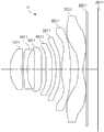
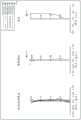
图1为示出光学成像系统的第一示例的视图,并且图2示出了图1的光学成像系统的像差曲线。FIG. 1 is a view showing a first example of an optical imaging system, and FIG. 2 shows aberration curves of the optical imaging system of FIG. 1 .
光学成像系统1包括第一透镜1001、第二透镜2001、第三透镜3001、第四透镜4001、第五透镜5001、第六透镜6001和第七透镜7001。The
第一透镜1001具有正屈光力、凸的物侧面和凹的像侧面。第二透镜2001具有负屈光力、凸的物侧面和凹的像侧面。第三透镜3001具有正屈光力、凸的物侧面和凹的像侧面。第四透镜4001具有负屈光力、凸的物侧面和凹的像侧面。第五透镜5001具有负屈光力、凸的物侧面和凹的像侧面。第六透镜6001具有正屈光力、凸的物侧面和凸的像侧面。另外,在第六透镜6001的物侧面和像侧面中的任一个面或两个面上形成至少一个反曲点。第七透镜7001具有负屈光力、凹的物侧面和凹的像侧面。另外,在第七透镜7001的物侧面和像侧面中的任一个面或两个面上形成至少一个反曲点。The
光学成像系统1还包括光阑、滤光片8001和图像传感器9001。光阑设置在第一透镜1001与第二透镜2001之间,以调节入射至图像传感器9001上的光的量。滤光片8001设置在第七透镜7001与图像传感器9001之间以阻挡红外线。图像传感器9001形成成像面,在该成像面上形成目标的图像。虽然未在图1中示出,但光阑设置在距第一透镜1001的物侧面朝向光学成像系统1的像侧0.818mm的距离处。该距离等于TTL-SL并且可以从稍后在本申请中呈现的表47中列出的示例1的TTL和SL的值计算出。The
下表1示出了构建图1的光学成像系统1的透镜和其它元件的物理特性,并且下表2示出了图1的透镜的非球面系数。Table 1 below shows physical properties of lenses and other elements constituting the
表1Table 1

表2Table 2

第二示例Second example
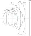
图3是示出光学成像系统的第二示例的视图,并且图4示出了图3的光学成像系统的像差曲线。FIG. 3 is a view showing a second example of the optical imaging system, and FIG. 4 shows aberration curves of the optical imaging system of FIG. 3 .
光学成像系统2包括第一透镜1002、第二透镜2002、第三透镜3002、第四透镜4002、第五透镜5002、第六透镜6002和第七透镜7002。The
第一透镜1002具有正屈光力、凸的物侧面和凹的像侧面。第二透镜2002具有正屈光力、凸的物侧面和凸的像侧面。第三透镜3002具有负屈光力、凸的物侧面和凹的像侧面。第四透镜4002具有负屈光力、凹的物侧面和凸的像侧面。第五透镜5002具有正屈光力、凸的物侧面和凹的像侧面。第六透镜6002具有负屈光力、凸的物侧面和凹的像侧面。另外,在第六透镜6002的物侧面和像侧面中的任一个面或两个面上形成至少一个反曲点。第七透镜7002具有正屈光力、凸的物侧面和凹的像侧面。另外,在第七透镜7002的物侧面和像侧面中的任一个面或两个面上形成至少一个反曲点。The
光学成像系统2还包括光阑、滤光片8002和图像传感器9002。光阑设置在第二透镜2002与第三透镜3002之间,以调节入射至图像传感器9002上的光的量。滤光片8002设置在第七透镜7002与图像传感器9002之间以阻挡红外线。图像传感器9002形成成像面,在该成像面上形成目标的图像。虽然未在图3中示出,但光阑设置在距第一透镜1002的物侧面朝向光学成像系统2的像侧1.259mm的距离处。该距离等于TTL-SL并且可以从稍后在本申请中呈现的表47中列出的示例2的TTL和SL的值计算出。The
下表3示出了构建图3的光学成像系统2的透镜和其它元件的物理特性,并且下表4示出了图3的透镜的非球面系数。Table 3 below shows physical properties of lenses and other elements constituting the
表3Table 3

表4Table 4


第三示例Third Example
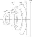
图5是示出光学成像系统的第三示例的视图,并且图6示出了图5的光学成像系统的像差曲线。FIG. 5 is a view showing a third example of the optical imaging system, and FIG. 6 shows aberration curves of the optical imaging system of FIG. 5 .
光学成像系统3包括第一透镜1003、第二透镜2003、第三透镜3003、第四透镜4003、第五透镜5003、第六透镜6003和第七透镜7003。The
第一透镜1003具有正屈光力、凸的物侧面和凹的像侧面。第二透镜2003具有正屈光力、凸的物侧面和凸的像侧面。第三透镜3003具有负屈光力、凸的物侧面和凹的像侧面。第四透镜4003具有负屈光力、凹的物侧面和凸的像侧面。第五透镜5003具有正屈光力、凸的物侧面和凹的像侧面。第六透镜6003具有负屈光力、凸的物侧面和凹的像侧面。另外,在第六透镜6003的物侧面和像侧面中的任一个面或两个面上形成至少一个反曲点。第七透镜7003具有正屈光力、凸的物侧面和凹的像侧面。另外,在第七透镜7003的物侧面和像侧面中的任一个面或两个面上形成至少一个反曲点。The
光学成像系统3还包括光阑、滤光片8003和图像传感器9003。光阑设置在第二透镜2003与第三透镜3003之间,以调节入射至图像传感器9003上的光的量。滤光片8003设置在第七透镜7003与图像传感器9003之间以阻挡红外线。图像传感器9003形成成像面,在该成像面上形成目标的图像。虽然未在图5中示出,但是光阑设置在距第一透镜1003的物侧面朝向光学成像系统3的像侧1.169mm的距离处。该距离等于TTL-SL并且可以从稍后在本申请中呈现的表47中列出的示例3的TTL和SL的值计算出。The
下表5示出了构建图5的光学成像系统3的透镜和其它元件的物理特性,并且下表6示出了图5的透镜的非球面系数。Table 5 below shows physical properties of lenses and other elements constituting the
表5Table 5

表6Table 6


第四示例Fourth Example
图7是示出光学成像系统的第四示例的视图,并且图8示出了图7的光学成像系统的像差曲线。FIG. 7 is a view showing a fourth example of the optical imaging system, and FIG. 8 shows aberration curves of the optical imaging system of FIG. 7 .
光学成像系统4包括第一透镜1004、第二透镜2004、第三透镜3004、第四透镜4004、第五透镜5004、第六透镜6004和第七透镜7004。The optical imaging system 4 includes a
第一透镜1004具有负屈光力、凸的物侧面和凹的像侧面。第二透镜2004具有正屈光力、凸的物侧面和凹的像侧面。第三透镜3004具有负屈光力、凸的物侧面和凹的像侧面。第四透镜4004具有负屈光力、凸的物侧面和凹的像侧面。第五透镜5004具有正屈光力、凸的物侧面和凹的像侧面。第六透镜6004具有正屈光力、凸的物侧面和凸的像侧面。另外,在第六透镜6004的物侧面和像侧面中的任一个面或两个面上形成至少一个反曲点。第七透镜7004具有负屈光力、凹的物侧面和凹的像侧面。另外,在第七透镜7004的物侧面和像侧面中的任一个面或两个面上形成至少一个反曲点。The
光学成像系统4还包括光阑、滤光片8004和图像传感器9004。光阑设置在第一透镜1004与第二透镜2004之间,以调节入射至图像传感器9004上的光的量。滤光片8004设置在第七透镜7004与图像传感器9004之间以阻挡红外线。图像传感器9004形成成像面,在该成像面上形成目标的图像。虽然未在图7中示出,但是光阑设置在距第一透镜1004的物侧面朝向光学成像系统4的像侧0.383mm的距离处。该距离等于TTL-SL并且可以从稍后在本申请中呈现的表47中列出的示例4的TTL和SL的值计算出。The optical imaging system 4 further includes an aperture, a
下表7示出了构建图7的光学成像系统4的透镜和其它元件的物理特性,并且下表8示出了图7的透镜的非球面系数。Table 7 below shows physical properties of lenses and other elements constituting the optical imaging system 4 of FIG. 7 , and Table 8 below shows aspheric coefficients of the lenses of FIG. 7 .
表7Table 7


表8Table 8
第五示例Fifth example
图9是示出光学成像系统的第五示例的视图,并且图10示出了图9的光学成像系统的像差曲线。FIG. 9 is a view showing a fifth example of the optical imaging system, and FIG. 10 shows aberration curves of the optical imaging system of FIG. 9 .
光学成像系统5包括第一透镜1005、第二透镜2005、第三透镜3005、第四透镜4005、第五透镜5005、第六透镜6005和第七透镜7005。The
第一透镜1005具有正屈光力、凸的物侧面和凹的像侧面。第二透镜2005具有负屈光力、凸的物侧面和凹的像侧面。第三透镜3005具有负屈光力、凸的物侧面和凹的像侧面。第四透镜4005具有正屈光力、凸的物侧面和凹的像侧面。第五透镜5005具有负屈光力、凹的物侧面和凸的像侧面。第六透镜6005具有正屈光力、凸的物侧面和凸的像侧面。另外,在第六透镜6005的物侧面和像侧面中的任一个面或两个面上形成至少一个反曲点。第七透镜7005具有负屈光力、凹的物侧面和凹的像侧面。另外,在第七透镜7005的物侧面和像侧面中的任一个面或两个面上形成至少一个反曲点。The
光学成像系统5还包括光阑、滤光片8005和图像传感器9005。光阑设置在第一透镜1005与第二透镜2005之间,以调节入射至图像传感器9005上的光的量。滤光片8005设置在第七透镜7005与图像传感器9005之间以阻挡红外线。图像传感器9005形成成像面,在该成像面上形成目标的图像。虽然未在图9中示出,但是光阑设置在距第一透镜1005的物侧面朝向光学成像系统5的像侧0.731mm的距离处。该距离等于TTL-SL并且可以从稍后在本申请中呈现的表47中列出的示例5的TTL和SL的值计算出。The
下表9示出了构建图9的光学成像系统5的透镜和其它元件的物理特性,并且下表10示出了图9的透镜的非球面系数。Table 9 below shows physical properties of lenses and other elements constituting the
表9Table 9


表10Table 10
第六示例Sixth Example
图11是示出光学成像系统的第六示例的视图,并且图12示出图11的光学成像系统的像差曲线。FIG. 11 is a view showing a sixth example of the optical imaging system, and FIG. 12 shows aberration curves of the optical imaging system of FIG. 11 .
光学成像系统6包括第一透镜1006、第二透镜2006、第三透镜3006、第四透镜4006、第五透镜5006、第六透镜6006和第七透镜7006。The
第一透镜1006具有正屈光力、凸的物侧面和凹的像侧面。第二透镜2006具有负屈光力、凸的物侧面和凹的像侧面。第三透镜3006具有负屈光力、凸的物侧面和凹的像侧面。第四透镜4006具有正屈光力、凸的物侧面和凹的像侧面。第五透镜5006具有负屈光力、凹的物侧面和凸的像侧面。第六透镜6006具有正屈光力、凸的物侧面和凸的像侧面。另外,在第六透镜6006的物侧面和像侧面中的任一个面或两个面上形成至少一个反曲点。第七透镜7006具有负屈光力、凹的物侧面和凹的像侧面。另外,在第七透镜7006的物侧面和像侧面中的任一个面或两个面上形成至少一个反曲点。The
光学成像系统6还包括光阑、滤光片8006和图像传感器9006。光阑设置在第一透镜1006与第二透镜2006之间,以调节入射至图像传感器9006上的光的量。滤光片8006设置在第七透镜7006与图像传感器9006之间以阻挡红外线。图像传感器9006形成成像面,在该成像面上形成目标的图像。虽然未在图11中示出,但是光阑设置在距第一透镜1006的物侧面朝向光学成像系统6的像侧0.675mm的距离处。该距离等于TTL-SL并且可以从稍后在本申请中呈现的表47中列出的示例6的TTL和SL的值计算出。The
下表11示出了构建图11的光学成像系统6的透镜和其它元件的物理特性,并且下表12示出了图11的透镜的非球面系数。Table 11 below shows physical properties of lenses and other elements constituting the
表11Table 11


表12Table 12
第七示例Example 7
图13是示出光学成像系统的第七示例的视图,并且图14示出了图13的光学成像系统的像差曲线。FIG. 13 is a view showing a seventh example of the optical imaging system, and FIG. 14 shows aberration curves of the optical imaging system of FIG. 13 .
光学成像系统7包括第一透镜1007、第二透镜2007、第三透镜3007、第四透镜4007、第五透镜5007、第六透镜6007和第七透镜7007。The
第一透镜1007具有正屈光力、凸的物侧面和凹的像侧面。第二透镜2007具有正屈光力、凸的物侧面和凸的像侧面。第三透镜3007具有负屈光力、凸的物侧面和凹的像侧面。第四透镜4007具有负屈光力、凸的物侧面和凹的像侧面。第五透镜5007具有正屈光力、凸的物侧面和凹的像侧面。第六透镜6007具有负屈光力、凸的物侧面和凹的像侧面。另外,在第六透镜6007的物侧面和像侧面中的任一个面或两个面上形成至少一个反曲点。第七透镜7007具有负屈光力、凸的物侧面和凹的像侧面。另外,在第七透镜7007的物侧面和像侧面中的任一个面或两个面上形成至少一个反曲点。The
光学成像系统7还包括光阑、滤光片8007和图像传感器9007。光阑设置在第二透镜2007与第三透镜3007之间,以调节入射至图像传感器9007上的光的量。滤光片8007设置在第七透镜7007与图像传感器9007之间以阻挡红外线。图像传感器9007形成成像面,在该成像面上形成目标的图像。虽然未在图13中示出,但是光阑设置在距第一透镜1007的物侧面朝向光学成像系统7的像侧1.158mm的距离处。该距离等于TTL-SL并且可以从稍后在本申请中呈现的表47中列出的示例7的TTL和SL的值计算出。The
下表13示出了构建图13的光学成像系统7的透镜和其它元件的物理特性,并且下表14示出了图13的透镜的非球面系数。Table 13 below shows physical properties of lenses and other elements constituting the
表13Table 13

表14Table 14
第八示例Example 8
图15是示出光学成像系统的第八示例的视图,并且图16示出图15的光学成像系统的像差曲线。FIG. 15 is a view showing an eighth example of the optical imaging system, and FIG. 16 shows aberration curves of the optical imaging system of FIG. 15 .
光学成像系统8包括第一透镜1008、第二透镜2008、第三透镜3008、第四透镜4008、第五透镜5008、第六透镜6008和第七透镜7008。The
第一透镜1008具有正屈光力、凸的物侧面和凹的像侧面。第二透镜2008具有正屈光力、凸的物侧面和凸的像侧面。第三透镜3008具有负屈光力、凸的物侧面和凹的像侧面。第四透镜4008具有正屈光力、凸的物侧面和凹的像侧面。第五透镜5008具有正屈光力、凸的物侧面和凹的像侧面。第六透镜6008具有负屈光力、凸的物侧面和凹的像侧面。另外,在第六透镜6008的物侧面和像侧面中的任一个面或两个面上形成至少一个反曲点。第七透镜7008具有负屈光力、凸的物侧面和凹的像侧面。另外,在第七透镜7008的物侧面和像侧面中的任一个面或两个面上形成至少一个反曲点。The
光学成像系统8还包括光阑、滤光片8008和图像传感器9008。光阑设置在第二透镜2008与第三透镜3008之间,以调节入射至图像传感器9008上的光的量。滤光片8008设置在第七透镜7008与图像传感器9008之间以阻挡红外线。图像传感器9008形成成像面,在该成像面上形成目标的图像。虽然未在图15中示出,但是光阑设置在距第一透镜1008的物侧面朝向光学成像系统8的像侧的1.179mm的距离处。该距离等于TTL-SL并且可以从稍后在本申请中呈现的表47中列出的示例8的TTL和SL的值计算出。The
下表15示出了构建图15的光学成像系统8的透镜和其它元件的物理特性,并且下表16示出了图15的透镜的非球面系数。Table 15 below shows physical properties of lenses and other elements constituting the
表15Table 15

表16Table 16


第九示例Ninth Example
图17是示出光学成像系统的第九示例的视图,并且图18示出图17的光学成像系统的像差曲线。FIG. 17 is a view showing a ninth example of the optical imaging system, and FIG. 18 shows aberration curves of the optical imaging system of FIG. 17 .
光学成像系统9包括第一透镜1009、第二透镜2009、第三透镜3009、第四透镜4009、第五透镜5009、第六透镜6009和第七透镜7009。The
第一透镜1009具有正屈光力、凸的物侧面和凹的像侧面。第二透镜2009具有负屈光力、凸的物侧面和凹的像侧面。第三透镜3009具有正屈光力、凸的物侧面和凹的像侧面。第四透镜4009具有正屈光力、凸的物侧面和凹的像侧面。第五透镜5009具有负屈光力、凹的物侧面和凸的像侧面。第六透镜6009具有正屈光力、凸的物侧面和凸的像侧面。另外,在第六透镜6009的物侧面和像侧面中的任一个面或两个面上形成至少一个反曲点。第七透镜7009具有负屈光力、凹的物侧面和凹的像侧面。另外,在第七透镜7009的物侧面和像侧面中的任一个面或两个面上形成至少一个反曲点。The
光学成像系统9还包括光阑、滤光片8009和图像传感器9009。光阑设置在第一透镜1009与第二透镜2009之间,以调节入射至图像传感器9009上的光的量。滤光片8009设置在第七透镜7009与图像传感器9009之间以阻挡红外线。图像传感器9009形成成像面,在该成像面上形成目标的图像。虽然未在图17中示出,但是光阑设置在距第一透镜1009的物侧面朝向光学成像系统9的像侧0.683mm的距离处。该距离等于TTL-SL并且可以从稍后在本申请中呈现的表47中列出的示例9的TTL和SL的值计算出。The
下表17示出了构建图17的光学成像系统9的透镜和其它元件的物理特性,并且下表18示出了图17的透镜的非球面系数。Table 17 below shows physical properties of lenses and other elements constituting the
表17Table 17

表18Table 18


第十示例Example 10
图19是示出光学成像系统的第十示例的视图,并且图20示出了图19的光学成像系统的像差曲线。FIG. 19 is a view showing a tenth example of the optical imaging system, and FIG. 20 shows aberration curves of the optical imaging system of FIG. 19 .
光学成像系统10包括第一透镜1010、第二透镜2010、第三透镜3010、第四透镜4010、第五透镜5010、第六透镜6010和第七透镜7010。The
第一透镜1010具有正屈光力、凸的物侧面和凹的像侧面。第二透镜2010具有负屈光力、凸的物侧面和凹的像侧面。第三透镜3010具有正屈光力、凸的物侧面和凹的像侧面。第四透镜4010具有正屈光力、凸的物侧面和凹的像侧面。第五透镜5010具有负屈光力、凹的物侧面和凸的像侧面。第六透镜6010具有负屈光力、凸的物侧面和凹的像侧面。另外,在第六透镜6010的物侧面和像侧面中的任一个面或两个面上形成至少一个反曲点。第七透镜7010具有负屈光力、凸的物侧面和凹的像侧面。另外,在第七透镜7010的物侧面和像侧面中的任一个面或两个面上形成至少一个反曲点。The
光学成像系统10还包括光阑ST、滤光片8010和图像传感器9010。光阑ST设置在第一透镜1010与第二透镜2010之间,以调节入射至图像传感器9010上的光的量。滤光片8010设置在第七透镜7010与图像传感器9010之间以阻挡红外线。图像传感器9010形成成像面,在该成像面上形成目标的图像。光阑ST设置在距第一透镜1010的物侧面朝向光学成像系统10的像侧0.250mm的距离处。该距离等于TTL-SL并且可以从稍后在本申请中呈现的表47中列出的示例10的TTL和SL的值计算出。The
下表19示出了构建图19的光学成像系统10的透镜和其它元件的物理特性,并且下表20示出了图19的透镜的非球面系数。Table 19 below shows physical properties of lenses and other elements that construct the
表19Table 19


表20Table 20
第十一示例Example 11
图21是示出光学成像系统的第十一示例的视图,并且图22示出了图21的光学成像系统的像差曲线。FIG. 21 is a view showing an eleventh example of the optical imaging system, and FIG. 22 shows aberration curves of the optical imaging system of FIG. 21 .
光学成像系统11包括第一透镜1011、第二透镜2011、第三透镜3011、第四透镜4011、第五透镜5011、第六透镜6011和第七透镜7011。The
第一透镜1011具有正屈光力、凸的物侧面和凹的像侧面。第二透镜2011具有负屈光力、凸的物侧面和凹的像侧面。第三透镜3011具有正屈光力、凸的物侧面和凹的像侧面。第四透镜4011具有正屈光力、凸的物侧面和凹的像侧面。第五透镜5011具有正屈光力、凹的物侧面和凸的像侧面。第六透镜6011具有正屈光力、凸的物侧面和凸的像侧面。另外,在第六透镜6011的物侧面和像侧面中的任一个面或两个面上形成至少一个反曲点。第七透镜7011具有负屈光力、凹的物侧面和凹的像侧面。另外,在第七透镜7011的物侧面和像侧面中的任一个面或两个面上形成至少一个反曲点。The
光学成像系统11还包括光阑、滤光片8011和图像传感器9011。光阑设置在第一透镜1011与第二透镜2011之间,以调节入射至图像传感器9011上的光的量。滤光片8011设置在第七透镜7011和图像传感器9011之间以阻挡红外线。图像传感器9011形成成像面,在该成像面上形成目标的图像。虽然未在图21中示出,但是光阑设置在距第一透镜1011的物侧面朝向光学成像系统11的像侧0.768mm的距离处。该距离等于TTL-SL并且可以从稍后在本申请中呈现的表47中列出的示例11的TTL和SL的值计算出。The
下表21示出了构建图21的光学成像系统11的透镜和其它元件的物理特性,并且下表22示出了图21的透镜的非球面系数。The following Table 21 shows the physical properties of the lenses and other elements constituting the
表21Table 21


表22Table 22
第十二示例Example 12
图23是示出光学成像系统的第十二示例的视图,并且图24示出了图23的光学成像系统的像差曲线。FIG. 23 is a view showing a twelfth example of the optical imaging system, and FIG. 24 shows aberration curves of the optical imaging system of FIG. 23 .
光学成像系统12包括第一透镜1012、第二透镜2012、第三透镜3012、第四透镜4012、第五透镜5012、第六透镜6012和第七透镜7012。The
第一透镜1012具有正屈光力、凸的物侧面和凹的像侧面。第二透镜2012具有负屈光力、凸的物侧面和凹的像侧面。第三透镜3012具有正屈光力、凸的物侧面和凹的像侧面。第四透镜4012具有正屈光力、凸的物侧面和凸的像侧面。第五透镜5012具有负屈光力、凹的物侧面和凸的像侧面。第六透镜6012具有正屈光力、凸的物侧面和凸的像侧面。另外,在第六透镜6012的物侧面和像侧面中的任一个面或两个面上形成至少一个反曲点。第七透镜7012具有负屈光力、凹的物侧面和凹的像侧面。另外,在第七透镜7012的物侧面和像侧面中的任一个面或两个面上形成至少一个反曲点。The
光学成像系统12还包括光阑、滤光片8012和图像传感器9012。光阑设置在第一透镜1012与第二透镜2012之间,以调节入射至图像传感器9012上的光的量。滤光片8012设置在第七透镜7012与图像传感器9012之间以阻挡红外线。图像传感器9012形成成像面,在该成像面上形成目标的图像。虽然未在图23中示出,但是光阑设置在距第一透镜1012的物侧面朝向光学成像系统12的像侧0.62mm的距离处。该距离等于TTL-SL并且可以从稍后在本申请中呈现的表47中列出的示例12的TTL和SL的值计算出。The
下表23示出了构建图23的光学成像系统12的透镜和其它元件的物理特性,并且下表24示出了图23的透镜的非球面系数。Table 23 below shows the physical properties of the lenses and other elements that construct the
表23Table 23


表24Table 24
第十三示例Example 13
图25是示出光学成像系统的第十三示例的视图,并且图26示出了图25的光学成像系统的像差曲线。FIG. 25 is a view showing a thirteenth example of the optical imaging system, and FIG. 26 shows aberration curves of the optical imaging system of FIG. 25 .
光学成像系统13包括第一透镜1013、第二透镜2013、第三透镜3013、第四透镜4013、第五透镜5013、第六透镜6013和第七透镜7013。The
第一透镜1013具有正屈光力、凸的物侧面和凹的像侧面。第二透镜2013具有负屈光力、凸的物侧面和凹的像侧面。第三透镜3013具有负屈光力、凸的物侧面和凹的像侧面。第四透镜4013具有正屈光力、凸的物侧面和凹的像侧面。第五透镜5013具有正屈光力、凹的物侧面和凸的像侧面。第六透镜6013具有正屈光力、凸的物侧面和凸的像侧面。另外,在第六透镜6013的物侧面和像侧面中的任一个面或两个面上形成至少一个反曲点。第七透镜7013具有负屈光力、凹的物侧面和凹的像侧面。另外,在第七透镜7013的物侧面和像侧面中的任一个面或两个面上形成至少一个反曲点。The first lens 1013 has a positive refractive power, a convex object side surface, and a concave image side surface. The
光学成像系统13还包括光阑、滤光片8013和图像传感器9013。光阑设置在第一透镜1013与第二透镜2013之间,以调节入射至图像传感器9013上的光的量。滤光片8013设置在第七透镜7013与图像传感器9013之间以阻挡红外线。图像传感器9013形成成像面,在该成像面上形成目标的图像。虽然未在图25中示出,但是光阑设置在距第一透镜1013的物侧面朝向光学成像系统13的像侧0.641mm的距离处。该距离等于TTL-SL并且可以从稍后在本申请中呈现的表47中列出的示例13的TTL和SL的值计算出。The
下表25示出了构建图25的光学成像系统13的透镜和其它元件的物理特性,并且下表26示出了图25的透镜的非球面系数。Table 25 below shows the physical properties of the lenses and other elements that construct the
表25Table 25

表26Table 26


第十四示例Example 14
图27是示出光学成像系统的第十四示例的视图,并且图28示出了图27的光学成像系统的像差曲线。FIG. 27 is a view showing a fourteenth example of the optical imaging system, and FIG. 28 shows aberration curves of the optical imaging system of FIG. 27 .
光学成像系统14包括第一透镜1014、第二透镜2014、第三透镜3014、第四透镜4014、第五透镜5014、第六透镜6014和第七透镜7014。The
第一透镜1014具有正屈光力、凸的物侧面和凹的像侧面。第二透镜2014具有负屈光力、凸的物侧面和凹的像侧面。第三透镜3014具有负屈光力、凸的物侧面和凹的像侧面。第四透镜4014具有正屈光力、凸的物侧面和凸的像侧面。第五透镜5014具有负屈光力、凹的物侧面和凸的像侧面。第六透镜6014具有负屈光力、凸的物侧面和凹的像侧面。另外,在第六透镜6014的物侧面和像侧面中的任一个面或两个面上形成至少一个反曲点。第七透镜7014具有负屈光力、凸的物侧面和凹的像侧面。另外,在第七透镜7014的物侧面和像侧面中的任一个面或两个面上形成至少一个反曲点。The
光学成像系统14还包括光阑、滤光片8014和图像传感器9014。光阑设置在第二透镜2014与第三透镜3014之间,以调节入射至图像传感器9014上的光的量。滤光片8014设置在第七透镜7014与图像传感器9014之间以阻挡红外线。图像传感器9014形成成像面,在该成像面上形成目标的图像。虽然未在图27中示出,但是光阑设置在距第一透镜1014的物侧面朝向光学成像系统14的像侧1.070mm的距离处。该距离等于TTL-SL并且可以从稍后在本申请中呈现的表47中列出的示例14的TTL和SL的值计算出。The
下表27示出了构建图27的光学成像系统14的透镜和其它元件的物理特性,并且下表28示出了图27的透镜的非球面系数。Table 27 below shows the physical properties of the lenses and other elements that construct the
表27Table 27

表28Table 28


第十五示例Example 15
图29是示出光学成像系统的第十五示例的视图,并且图30示出图29的光学成像系统的像差曲线。FIG. 29 is a view showing a fifteenth example of the optical imaging system, and FIG. 30 shows aberration curves of the optical imaging system of FIG. 29 .
光学成像系统15包括第一透镜1015、第二透镜2015、第三透镜3015、第四透镜4015、第五透镜5015、第六透镜6015和第七透镜7015。The
第一透镜1015具有正屈光力、凸的物侧面和凹的像侧面。第二透镜2015具有正屈光力、凸的物侧面和凹的像侧面。第三透镜3015具有负屈光力、凸的物侧面和凹的像侧面。第四透镜4015具有负屈光力、凸的物侧面和凹的像侧面。第五透镜5015具有正屈光力、凸的物侧面和凹的像侧面。第六透镜6015具有正屈光力、凸的物侧面和凸的像侧面。另外,在第六透镜6015的物侧面和像侧面中的任一个面或两个面上形成至少一个反曲点。第七透镜7015具有负屈光力、凹的物侧面和凹的像侧面。另外,在第七透镜7015的物侧面和像侧面中的任一个面或两个面上形成至少一个反曲点。The
光学成像系统15还包括光阑、滤光片8015和图像传感器9015。光阑设置在第二透镜2015与第三透镜3015之间,以调节入射至图像传感器9015上的光的量。滤光片8015设置在第七透镜7015与图像传感器9015之间以阻挡红外线。图像传感器9015形成成像面,在该成像面上形成目标的图像。虽然未在图29中示出,但是光阑设置在距第一透镜1015的物侧面朝向光学成像系统15的像侧1.002mm的距离处。该距离等于TTL-SL并且可以从稍后在本申请中呈现的表47中列出的示例15的TTL和SL的值计算出。The
下表29示出了构建图29的光学成像系统15的透镜和其它元件的物理特性,并且下表30示出了图29的透镜的非球面系数。Table 29 below shows the physical properties of the lenses and other elements that construct the
表29Table 29

表30Table 30
第十六示例Example 16
图31是示出光学成像系统的第十六示例的视图,并且图32示出了图31的光学成像系统的像差曲线。FIG. 31 is a view showing a sixteenth example of the optical imaging system, and FIG. 32 shows aberration curves of the optical imaging system of FIG. 31 .
光学成像系统16包括第一透镜1016、第二透镜2016、第三透镜3016、第四透镜4016、第五透镜5016、第六透镜6016和第七透镜7016。The
第一透镜1016具有负屈光力、凸的物侧面和凹的像侧面。第二透镜2016具有正屈光力、凸的物侧面和凹的像侧面。第三透镜3016具有负屈光力、凸的物侧面和凹的像侧面。第四透镜4016具有负屈光力、凸的物侧面和凹的像侧面。第五透镜5016具有正屈光力、凸的物侧面和凹的像侧面。第六透镜6016具有正屈光力、凸的物侧面和凸的像侧面。另外,在第六透镜6016的物侧面和像侧面中的任一个面或两个面上形成至少一个反曲点。第七透镜7016具有负屈光力、凹的物侧面和凹的像侧面。另外,在第七透镜7016的物侧面和像侧面中的任一个面或两个面上形成至少一个反曲点。The
光学成像系统16还包括光阑、滤光片8016和图像传感器9016。光阑设置在第一透镜1016与第二透镜2016之间,以调节入射至图像传感器9016上的光的量。滤光片8016设置在第七透镜7016和图像传感器9016之间以阻挡红外线。图像传感器9016形成成像面,在该成像面上形成目标的图像。虽然未在图31中示出,但是光阑设置在距第一透镜1016的物侧面朝向光学成像系统16的像侧0.374mm的距离处。该距离等于TTL-SL并且可以从稍后在本申请中呈现的表47中列出的示例16的TTL和SL的值计算出。The
下表31示出了构建图31的光学成像系统16的透镜和其它元件的物理特性,并且下表32示出了图31的透镜的非球面系数。Table 31 below shows the physical properties of the lenses and other elements that construct the
表31Table 31


表32Table 32
第十七示例Example 17
图33是示出光学成像系统的第十七示例的视图,并且图34示出了图33的光学成像系统的像差曲线。FIG. 33 is a view showing a seventeenth example of the optical imaging system, and FIG. 34 shows aberration curves of the optical imaging system of FIG. 33 .
光学成像系统17包括第一透镜1017、第二透镜2017、第三透镜3017、第四透镜4017、第五透镜5017、第六透镜6017和第七透镜7017。The
第一透镜1017具有正屈光力、凸的物侧面和凹的像侧面。第二透镜2017具有负屈光力、凸的物侧面和凹的像侧面。第三透镜3017具有正屈光力、凸的物侧面和凹的像侧面。第四透镜4017具有负屈光力、凸的物侧面和凹的像侧面。第五透镜5017具有负屈光力、凸的物侧面和凹的像侧面。第六透镜6017具有正屈光力、凸的物侧面和凸的像侧面。另外,在第六透镜6017的物侧面和像侧面中的任一个面或两个面上形成至少一个反曲点。第七透镜7017具有负屈光力、凹的物侧面和凹的像侧面。另外,在第七透镜7017的物侧面和像侧面中的任一个面或两个面上形成至少一个反曲点。The first lens 1017 has a positive refractive power, a convex object-side surface, and a concave image-side surface. The
光学成像系统17还包括光阑、滤光片8017和图像传感器9017。光阑设置在第一透镜1017与第二透镜2017之间,以调节入射至图像传感器9017上的光的量。滤光片8017设置在第七透镜7017与图像传感器9017之间以阻挡红外线。图像传感器9017形成成像面,在该成像面上形成目标的图像。虽然未在图33中示出,但是光阑设置在距第一透镜1017的物侧面朝向光学成像系统17的像侧0.920mm的距离处。该距离等于TTL-SL并且可以从稍后在本申请中呈现的表47中列出的示例17的TTL和SL的值计算出。The
下表33示出了构建图33的光学成像系统17的透镜和其它元件的物理特性,并且下表34示出了图33的透镜的非球面系数。Table 33 below shows the physical properties of the lenses and other elements that construct the
表33Table 33


表34Table 34
第十八示例Example 18
图35是示出光学成像系统的第十八示例的视图,并且图36示出了图35的光学成像系统的像差曲线。FIG. 35 is a view showing an eighteenth example of the optical imaging system, and FIG. 36 shows aberration curves of the optical imaging system of FIG. 35 .
光学成像系统18包括第一透镜1018、第二透镜2018、第三透镜3018、第四透镜4018、第五透镜5018、第六透镜6018和第七透镜7018。The
第一透镜1018具有正屈光力、凸的物侧面和凹的像侧面。第二透镜2018具有正屈光力、凸的物侧面和凹的像侧面。第三透镜3018具有负屈光力、凸的物侧面和凹的像侧面。第四透镜4018具有正屈光力、凸的物侧面和凹的像侧面。第五透镜5018具有负屈光力、凸的物侧面和凹的像侧面。第六透镜6018具有正屈光力、凸的物侧面和凹的像侧面。另外,在第六透镜6018的物侧面和像侧面中的任一个面或两个面上形成至少一个反曲点。第七透镜7018具有正屈光力、凸的物侧面和凹的像侧面。另外,在第七透镜7018的物侧面和像侧面中的任一个面或两个面上形成至少一个反曲点。The
光学成像系统18还包括光阑、滤光片8018和图像传感器9018。光阑设置在第二透镜2018与第三透镜3018之间,以调节入射至图像传感器9018上的光的量。滤光片8018设置在第七透镜7018与图像传感器9018之间以阻挡红外线。图像传感器9018形成成像面,在该成像面上形成目标的图像。虽然未在图35中示出,但是光阑设置在距第一透镜1018的物侧面朝向光学成像系统18的像侧1.082mm的距离处。该距离等于TTL-SL并且可以从稍后在本申请中呈现的表47中列出的示例18的TTL和SL的值计算出。The
下表35示出了构建图35的光学成像系统18的透镜和其它元件的物理特性,并且下表36示出了图35的透镜的非球面系数。Table 35 below shows the physical properties of the lenses and other elements that construct the
表35Table 35

表36Table 36
第十九示例Example 19
图37是示出光学成像系统的第十九示例的视图,并且图38示出了图37的光学成像系统的像差曲线。FIG. 37 is a view showing a nineteenth example of the optical imaging system, and FIG. 38 shows aberration curves of the optical imaging system of FIG. 37 .
光学成像系统19包括第一透镜1019、第二透镜2019、第三透镜3019、第四透镜4019、第五透镜5019、第六透镜6019和第七透镜7019。The
第一透镜1019具有正屈光力、凸的物侧面和凹的像侧面。第二透镜2019具有正屈光力、凸的物侧面和凹的像侧面。第三透镜3019具有负屈光力、凸的物侧面和凹的像侧面。第四透镜4019具有正屈光力、凸的物侧面和凹的像侧面。第五透镜5019具有负屈光力、凸的物侧面和凹的像侧面。第六透镜6019具有正屈光力、凸的物侧面和凹的像侧面。另外,在第六透镜6019的物侧面和像侧面中的任一个面或两个面上形成至少一个反曲点。第七透镜7019具有负屈光力、凸的物侧面和凹的像侧面。另外,在第七透镜7019的物侧面和像侧面中的任一个面或两个面上形成至少一个反曲点。The
光学成像系统19还包括光阑、滤光片8019和图像传感器9019。光阑设置在第二透镜2019与第三透镜3019之间,以调节入射至图像传感器9019上的光的量。滤光片8019设置在第七透镜7019与图像传感器9019之间以阻挡红外线。图像传感器9019形成成像面,在该成像面上形成目标的图像。虽然未在图37中示出,但是光阑设置在距第一透镜1019的物侧面朝向光学成像系统19的像侧1.201mm的距离处。该距离等于TTL-SL并且可以从稍后在本申请中呈现的表47中列出的示例19的TTL和SL的值计算出。The
下表37示出了构建图37的光学成像系统19的透镜和其它元件的物理特性,并且下表38示出了图37的透镜的非球面系数。Table 37 below shows the physical properties of the lenses and other elements that construct the
表37Table 37

表38Table 38


第二十示例Example 20
图39是示出光学成像系统的第二十示例的视图,并且图40示出了图39的光学成像系统的像差曲线。FIG. 39 is a view showing a twentieth example of the optical imaging system, and FIG. 40 shows aberration curves of the optical imaging system of FIG. 39 .
光学成像系统20包括第一透镜1020、第二透镜2020、第三透镜3020、第四透镜4020、第五透镜5020、第六透镜6020和第七透镜7020。The
第一透镜1020具有正屈光力、凸的物侧面和凹的像侧面。第二透镜2020具有负屈光力、凸的物侧面和凹的像侧面。第三透镜3020具有负屈光力、凸的物侧面和凹的像侧面。第四透镜4020具有正屈光力、凸的物侧面和凹的像侧面。第五透镜5020具有负屈光力、凸的物侧面和凹的像侧面。第六透镜6020具有负屈光力、凹的物侧面和凹的像侧面。另外,在第六透镜6020的物侧面和像侧面中的任一个面或两个面上形成至少一个反曲点。第七透镜7020具有正屈光力、凸的物侧面和凹的像侧面。另外,在第七透镜7020的物侧面和像侧面中的任一个面或两个面上形成至少一个反曲点。The
光学成像系统20还包括光阑、滤光片8020和图像传感器9020。光阑设置在第二透镜2020与第三透镜3020之间,以调节入射至图像传感器9020上的光的量。滤光片8020设置在第七透镜7020与图像传感器9020之间以阻挡红外线。图像传感器9020形成成像面,在该成像面上形成目标的图像。虽然未在图39中示出,但是光阑设置在距第一透镜1020的物侧面朝向光学成像系统20的像侧0.963mm的距离处。该距离等于TTL-SL并且可以从稍后在本申请中呈现的表47中列出的示例20的TTL和SL的值计算出。The
下表39示出了构建图39的光学成像系统20的透镜和其它元件的物理特性,并且下表40示出了图39的透镜的非球面系数。Table 39 below shows the physical properties of the lenses and other elements that construct the
表39Table 39

表40Table 40


第二十一示例Example 21
图41是示出光学成像系统的第二十一示例的视图,并且图42示出了图41的光学成像系统的像差曲线。FIG. 41 is a view showing a twenty-first example of the optical imaging system, and FIG. 42 shows aberration curves of the optical imaging system of FIG. 41 .
光学成像系统21包括第一透镜1021、第二透镜2021、第三透镜3021、第四透镜4021、第五透镜5021、第六透镜6021和第七透镜7021。The
第一透镜1021具有正屈光力、凸的物侧面和凹的像侧面。第二透镜2021具有负屈光力、凸的物侧面和凹的像侧面。第三透镜3021具有正屈光力、凹的物侧面和凸的像侧面。第四透镜4021具有负屈光力、凸的物侧面和凹的像侧面。第五透镜5021具有正屈光力、凹的物侧面和凸的像侧面。第六透镜6021具有正屈光力、凹的物侧面和凸的像侧面。另外,在第六透镜6021的物侧面和像侧面中的任一个面或两个面上形成至少一个反曲点。第七透镜7021具有负屈光力、凹的物侧面和凹的像侧面。另外,在第七透镜7021的物侧面和像侧面中的任一个面或两个面上形成至少一个反曲点。The
光学成像系统21还包括光阑、滤光片8021和图像传感器9021。光阑设置在第二透镜2021与第三透镜3021之间,以调节入射至图像传感器9021上的光的量。滤光片8021设置在第七透镜7021与图像传感器9021之间以阻挡红外线。图像传感器9021形成成像面,在该成像面上形成目标的图像。虽然未在图41中示出,但是光阑设置在距第一透镜1021的物侧面朝向光学成像系统21的像侧0.872mm的距离处。该距离等于TTL-SL并且可以从稍后在本申请中呈现的表47中列出的示例21的TTL和SL的值计算出。The
下表41示出了构建图41的光学成像系统21的透镜和其它元件的物理特性,并且下表42示出了图41的透镜的非球面系数。Table 41 below shows physical properties of lenses and other elements constituting the
表41Table 41


表42Table 42
第二十二示例Example 22
图43是示出光学成像系统的第二十二示例的视图,并且图44示出了图43的光学成像系统的像差曲线。FIG. 43 is a view showing a twenty-second example of the optical imaging system, and FIG. 44 shows aberration curves of the optical imaging system of FIG. 43 .
光学成像系统22包括第一透镜1022、第二透镜2022、第三透镜3022、第四透镜4022、第五透镜5022、第六透镜6022和第七透镜7022。The
第一透镜1022具有正屈光力、凸的物侧面和凹的像侧面。第二透镜2022具有负屈光力、凸的物侧面和凹的像侧面。第三透镜3022具有正屈光力、凹的物侧面和凸的像侧面。第四透镜4022具有正屈光力、凸的物侧面和凹的像侧面。第五透镜5022具有负屈光力、凸的物侧面和凹的像侧面。第六透镜6022具有正屈光力、凸的物侧面和凹的像侧面。另外,在第六透镜6022的物侧面和像侧面中的任一个面或两个面上形成至少一个反曲点。第七透镜7022具有正屈光力、凸的物侧面和凹的像侧面。另外,在第七透镜7022的物侧面和像侧面中的任一个面或两个面上形成至少一个反曲点。The
光学成像系统22还包括光阑、滤光片8022和图像传感器9022。光阑设置在第二透镜2022与第三透镜3022之间,以调节入射至图像传感器9022上的光的量。滤光片8022设置在第七透镜7022与图像传感器9022之间以阻挡红外线。图像传感器9022形成成像面,在该成像面上形成目标的图像。虽然未在图43中示出,但是光阑设置在距第一透镜1022的物侧面朝向光学成像系统22的像侧0.866mm的距离处。该距离等于TTL-SL并且可以从稍后在本申请中呈现的表47中列出的示例22的TTL和SL的值计算出。The
下表43示出了构建图43的光学成像系统22的透镜和其它元件的物理特性,并且下表44示出了图43的透镜的非球面系数。Table 43 below shows the physical properties of the lenses and other elements that construct the
表43Table 43


表44Table 44
第二十三示例Example 23
图45是示出光学成像系统的第二十三示例的视图,并且图46示出了图45的光学成像系统的像差曲线。FIG. 45 is a view showing a twenty-third example of the optical imaging system, and FIG. 46 shows aberration curves of the optical imaging system of FIG. 45 .
光学成像系统23包括第一透镜1023、第二透镜2023、第三透镜3023、第四透镜4023、第五透镜5023、第六透镜6023和第七透镜7023。The optical imaging system 23 includes a
第一透镜1023具有正屈光力、凸的物侧面和凹的像侧面。第二透镜2023具有负屈光力、凸的物侧面和凹的像侧面。第三透镜3023具有正屈光力、凹的物侧面和凸的像侧面。第四透镜4023具有正屈光力、凸的物侧面和凹的像侧面。第五透镜5023具有负屈光力、凸的物侧面和凹的像侧面。第六透镜6023具有正屈光力、凸的物侧面和凹的像侧面。另外,在第六透镜6023的物侧面和像侧面中的任一个面或两个面上形成至少一个反曲点。第七透镜7023具有正屈光力、凸的物侧面和凹的像侧面。另外,在第七透镜7023的物侧面和像侧面中的任一个面或两个面上形成至少一个反曲点。The
光学成像系统23还包括光阑、滤光片8023和图像传感器9023。光阑设置在第二透镜2023与第三透镜3023之间,以调节入射至图像传感器9023上的光的量。滤光片8023设置在第七透镜7023与图像传感器9023之间以阻挡红外线。图像传感器9023形成成像面,在该成像面上形成目标的图像。虽然未在图45中示出,但是光阑设置在距第一透镜1023的物侧面朝向光学成像系统23的像侧0.904mm的距离处。该距离等于TTL-SL并且可以从稍后在本申请中呈现的表47中列出的示例23的TTL和SL的值计算出。The optical imaging system 23 also includes an aperture, a
下表45示出了构建图45的光学成像系统23的透镜和其它元件的物理特性,并且下表46示出了图45的透镜的非球面系数。Table 45 below shows the physical properties of the lenses and other elements that construct the optical imaging system 23 of Figure 45, and Table 46 below shows the aspheric coefficients of the lenses of Figure 45.
表45Table 45

表46Table 46
下表47示出了本申请中所描述的示例1至23中的每个示例的光学成像系统的总焦距f、光学成像系统的总长度TTL(从第一透镜的物侧面到成像面的距离)、从光阑到成像面的距离SL、光学成像系统的f数(F No.)(光学成像系统的总焦距f除以光学成像系统的入瞳直径,其中,f和入瞳直径二者均以mm为单位表示)、成像面上的像高(IMG HT)(成像面的对角线长度的一半)以及光学成像系统的视场角(FOV)。f、TTL、SL和IMG HT的值以mm为单位表示。F No.的值为无量纲值。FOV的值以度为单位表示。Table 47 below shows the total focal length f of the optical imaging system, the total length TTL of the optical imaging system (the distance from the object side of the first lens to the imaging plane), the distance SL from the aperture to the imaging plane, the f-number (F No.) of the optical imaging system (the total focal length f of the optical imaging system divided by the entrance pupil diameter of the optical imaging system, where both f and the entrance pupil diameter are expressed in mm), the image height (IMG HT) on the imaging plane (half the diagonal length of the imaging plane), and the field of view (FOV) of the optical imaging system for each of Examples 1 to 23 described in the present application. The values of f, TTL, SL, and IMG HT are expressed in mm. The value of F No. is a dimensionless value. The value of FOV is expressed in degrees.
表47Table 47


下表48示出了本申请中描述的示例1至23中的每个示例的第一透镜的焦距f1、第二透镜的焦距f2、第三透镜的焦距f3、第四透镜的焦距f4,第五透镜的焦距f5、第六透镜的焦距f6和第七透镜的焦距f7(以mm为单位)。The following Table 48 shows the focal length f1 of the first lens, the focal length f2 of the second lens, the focal length f3 of the third lens, the focal length f4 of the fourth lens, the focal length f5 of the fifth lens, the focal length f6 of the sixth lens, and the focal length f7 of the seventh lens (in mm) of each of Examples 1 to 23 described in the present application.
表48Table 48


下表49示出了本申请中描述的示例1至23中的每个示例的第一透镜的边缘厚度(L1edge T)、第二透镜的边缘厚度(L2edge T)、第三透镜的边缘厚度(L3edge T)、第四透镜的边缘厚度(L4edge T)、第五透镜的边缘厚度(L5edge T)、第六透镜的边缘厚度(L6edgeT)以及第七透镜的边缘厚度(L7edge T)(以mm为单位)。The following Table 49 shows the edge thickness of the first lens (L1edge T), the edge thickness of the second lens (L2edge T), the edge thickness of the third lens (L3edge T), the edge thickness of the fourth lens (L4edge T), the edge thickness of the fifth lens (L5edge T), the edge thickness of the sixth lens (L6edgeT), and the edge thickness of the seventh lens (L7edge T) (in mm) of each of Examples 1 to 23 described in the present application.
表49Table 49


下表50示出了本申请中描述的示例1至23中的每个示例的第五透镜的物侧面的sag值(L5S1 sag)、第五透镜的像侧面的sag值(L5S2sag)、第七透镜的在第七透镜的物侧面的第一反曲点处的厚度(Yc71P1)、第七透镜的在第七透镜的物侧面的第二反曲点处的厚度(Yc71P2)、第七透镜的在第七透镜的像侧面的第一反曲点处的厚度(Yc72P1)以及第七透镜的在第七透镜的像侧面的第二反曲点处的厚度(Yc72P2)(以mm为单位)。Table 50 below shows the sag value (L5S1 sag) of the object-side surface of the fifth lens, the sag value (L5S2sag) of the image-side surface of the fifth lens, the thickness of the seventh lens at the first inflection point of the object-side surface of the seventh lens (Yc71P1), the thickness of the seventh lens at the second inflection point of the object-side surface of the seventh lens (Yc71P2), the thickness of the seventh lens at the first inflection point of the image-side surface of the seventh lens (Yc72P1), and the thickness of the seventh lens at the second inflection point of the image-side surface of the seventh lens (Yc72P2) (in mm) of each of Examples 1 to 23 described in the present application.
表50Table 50
下表51示出了本申请中描述的示例1至23中的每个示例的第一隔圈至第七隔圈中的每个隔圈的内径(以mm为单位)。SP1为第一隔圈的内径,SP2为第二隔圈的内径,SP3为第三隔圈的内径,SP4为第四隔圈的内径,SP5为第五隔圈的内径,SP6为第六隔圈的内径,以及SP7为第七隔圈的内径。Table 51 below shows the inner diameter (in mm) of each of the first to seventh spacers of each of Examples 1 to 23 described in the present application. SP1 is the inner diameter of the first spacer, SP2 is the inner diameter of the second spacer, SP3 is the inner diameter of the third spacer, SP4 is the inner diameter of the fourth spacer, SP5 is the inner diameter of the fifth spacer, SP6 is the inner diameter of the sixth spacer, and SP7 is the inner diameter of the seventh spacer.
表51Table 51
下表52示出了本申请中描述的示例1至23中的每个示例的第一透镜至第七透镜中的每片透镜的体积(以mm3为单位)。L1v为第一透镜的体积,L2v为第二透镜的体积,L3v为第三透镜的体积,L4v为第四透镜的体积,L5v为第五透镜的体积,L6v为第六透镜的体积,以及L7v为第七透镜的体积。Table 52 below shows the volume (in mm3 ) of each of the first to seventh lenses of each of Examples 1 to 23 described in the present application. L1v is the volume of the first lens, L2v is the volume of the second lens, L3v is the volume of the third lens, L4v is the volume of the fourth lens, L5v is the volume of the fifth lens, L6v is the volume of the sixth lens, and L7v is the volume of the seventh lens.
表52Table 52


下表53示出了本申请中描述的示例1至23中的每个示例的第一透镜至第七透镜中的每片透镜的重量(以mg为单位)。L1w为第一透镜的重量,L2w为第二透镜的重量,L3w为第三透镜的重量,L4w为第四透镜的重量,L5w为第五透镜的重量,L6w为第六透镜的重量,以及L7w为第七透镜的重量。The following Table 53 shows the weight (in mg) of each of the first to seventh lenses of each of Examples 1 to 23 described in the present application. L1w is the weight of the first lens, L2w is the weight of the second lens, L3w is the weight of the third lens, L4w is the weight of the fourth lens, L5w is the weight of the fifth lens, L6w is the weight of the sixth lens, and L7w is the weight of the seventh lens.
表53Table 53


下表54示出了本申请中描述的示例1至23中的每个示例的第一透镜至第七透镜中的每片透镜的总外径(包括肋)(以mm为单位)。L1TR为第一透镜的总外径,L2TR为第二透镜的总外径,L3TR为第三透镜的总外径,L4TR为第四透镜的总外径,L5TR为第五透镜的总外径,L6TR为第六透镜的总外径,以及L7TR为第七透镜的总外径。The following Table 54 shows the total outer diameter (including ribs) (in mm) of each of the first lens to the seventh lens of each of Examples 1 to 23 described in the present application. L1TR is the total outer diameter of the first lens, L2TR is the total outer diameter of the second lens, L3TR is the total outer diameter of the third lens, L4TR is the total outer diameter of the fourth lens, L5TR is the total outer diameter of the fifth lens, L6TR is the total outer diameter of the sixth lens, and L7TR is the total outer diameter of the seventh lens.
表54Table 54


下表55示出了本申请中描述的示例1至23中的每个示例的第一透镜至第七透镜中的每片透镜的肋的平坦部分的厚度(以mm为单位)。L1rt为第一透镜的肋的平坦部分的厚度,L2rt为第二透镜的肋的平坦部分的厚度,L3rt为第三透镜的肋的平坦部分的厚度,L4rt为第四透镜的肋的平坦部分的厚度,L5rt为第五透镜的肋的平坦部分的厚度,L6rt为第六透镜的肋的平坦部分的厚度,以及L7rt为第七透镜的肋的平坦部分的厚度。Table 55 below shows the thickness (in mm) of the flat portion of the rib of each of the first lens to the seventh lens in each of Examples 1 to 23 described in the present application. L1rt is the thickness of the flat portion of the rib of the first lens, L2rt is the thickness of the flat portion of the rib of the second lens, L3rt is the thickness of the flat portion of the rib of the third lens, L4rt is the thickness of the flat portion of the rib of the fourth lens, L5rt is the thickness of the flat portion of the rib of the fifth lens, L6rt is the thickness of the flat portion of the rib of the sixth lens, and L7rt is the thickness of the flat portion of the rib of the seventh lens.
表55Table 55


下表56示出了本申请中描述的示例1至23中的每个示例的以下项中的每一项的无量纲值:条件表达式1和7中的比值L1w/L7w、条件表达式2和8中的比值S6d/f、条件表达式3和9中的比值L1TR/L7TR、条件表达式4和10中的比值L1234TRavg/L7TR、条件表达式5和11中的比值L12345TRavg/L7TR以及条件表达式6和12中的比值|f123457-f|/f。这些比值中的每个比值的无量纲值均通过将以相同的测量单位表示的两个值相除而获得。Table 56 below shows the dimensionless value of each of the following items for each of Examples 1 to 23 described in the present application: the ratio L1w/L7w in
表56Table 56
图47和图48是示出彼此联接的光学成像系统和镜筒的示例的剖视图。47 and 48 are cross-sectional views illustrating examples of an optical imaging system and a lens barrel coupled to each other.
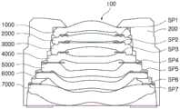
本申请中描述的光学成像系统100的示例可包括如图47和图48中所示的自对准结构。Examples of
在图47中所示的一个示例中,光学成像系统100包括自对准结构,该结构中,通过将四片连续透镜1000、2000、3000和4000彼此联接而将这四片透镜1000、2000、3000和4000的光轴与光学成像系统100的光轴对准。In one example shown in FIG. 47 , the
设置成最靠近光学成像系统100的物侧的第一透镜1000设置成与镜筒200的内表面接触以使第一透镜1000的光轴与光学成像系统100的光轴对准,第二透镜2000联接至第一透镜1000以使第二透镜2000的光轴与光学成像系统100的光轴对准,第三透镜3000联接至第二透镜2000以使第三透镜3000的光轴与光学成像系统100的光轴对准,并且第四透镜4000联接至第三透镜3000以使第四透镜4000的光轴与光学成像系统100的光轴对准。第二透镜2000至第四透镜4000可以设置成不与镜筒200的内表面接触。The
虽然图47示出了第一透镜1000至第四透镜4000彼此联接,但是彼此联接的四片连续透镜可改变成第二透镜2000至第五透镜5000、第三透镜3000至第六透镜6000或第四透镜4000至第七透镜7000。Although FIG. 47 shows that the first to
在图48中所示的另一示例中,光学成像系统100包括自对准结构,在该结构中,通过将五片连续透镜1000、2000、3000、4000和5000彼此联接而将这五片透镜1000、2000、3000、4000和5000的光轴与光学成像系统100的光轴对准。In another example shown in FIG. 48 , the
设置成最靠近光学成像系统100的物侧的第一透镜1000设置成与镜筒200的内表面接触以使第一透镜1000的光轴与光学成像系统100的光轴对准,第二透镜2000联接至第一透镜1000以使第二透镜2000的光轴与光学成像系统100的光轴对准,第三透镜3000联接至第二透镜2000以使第三透镜3000的光轴与光学成像系统100的光轴对准,第四透镜4000联接至第三透镜3000以使第四透镜4000的光轴与光学成像系统100的光轴对准,并且第五透镜5000联接至第四透镜4000以使第五透镜5000的光轴与光学成像系统100的光轴对准。第二透镜2000至第五透镜5000可以设置成不与镜筒200的内表面接触。The
虽然图48示出了第一透镜1000至第五透镜5000彼此联接,但是彼此联接的五片连续透镜可改变成第二透镜2000至第六透镜6000、或者第三透镜3000至第七透镜7000。Although FIG. 48 shows that the first to
图49是示出第七透镜的示例的剖视图。FIG. 49 is a cross-sectional view illustrating an example of the seventh lens.
图49示出了第七透镜的总外径(L7TR)、第七透镜的肋的平坦部分的厚度(L7rT)、第七透镜的边缘厚度(L7edge T)、第七透镜的在第七透镜的物侧面的第一反曲点处的厚度(Yc71P1)、第七透镜的在第七透镜的物侧面的第二反曲点处的厚度(Yc71P2)以及第七透镜的在第七透镜的像侧面的第一反曲点处的厚度(Yc72P1)。FIG49 shows a total outer diameter of the seventh lens (L7TR), a thickness of a flat portion of the rib of the seventh lens (L7rT), an edge thickness of the seventh lens (L7edge T), a thickness of the seventh lens at a first inflection point on the object side surface of the seventh lens (Yc71P1), a thickness of the seventh lens at a second inflection point on the object side surface of the seventh lens (Yc71P2), and a thickness of the seventh lens at a first inflection point on the image side surface of the seventh lens (Yc72P1).
图50是示出透镜的肋的形状的示例的剖视图。FIG. 50 is a cross-sectional view showing an example of the shape of a rib of a lens.
本申请中描述的光学成像系统100的示例可包括用于防止闪烁现象和反射的结构。Examples of the
例如,如图50中所示,可以对构建光学成像系统的第一透镜至第七透镜(1000、2000、3000、4000、5000、6000和7000)的肋进行部分表面处理,以使肋的表面粗糙。表面处理的方法可包括化学蚀刻和物理研磨,但不限于此。For example, as shown in Figure 50, the ribs of the first to seventh lenses (1000, 2000, 3000, 4000, 5000, 6000, and 7000) constituting the optical imaging system may be partially surface-treated to roughen the surface of the ribs. The surface treatment method may include chemical etching and physical grinding, but is not limited thereto.
表面处理区域EA可形成在从透镜的、光实际穿过的光学部分的边缘到肋的端部的整个区域中。然而,如图50中所示,可以不对包括凹部E11、E21和E22的非处理区域NEA进行表面处理,或者可对包括凹部E11、E21和E22的非处理区域NEA进行表面处理以使其具有与表面处理区域EA的粗糙度不同的粗糙度。形成在透镜的一个表面上的第一非处理区域NEA的宽度G1可以与形成在透镜的另一表面上的第二非处理区域NEA的宽度G2不同。在图50中所示的示例中,G1大于G2。The surface treatment area EA may be formed in the entire area from the edge of the optical portion of the lens through which light actually passes to the end of the rib. However, as shown in FIG. 50 , the non-treated area NEA including the recesses E11, E21, and E22 may not be surface treated, or the non-treated area NEA including the recesses E11, E21, and E22 may be surface treated to have a roughness different from that of the surface treatment area EA. The width G1 of the first non-treated area NEA formed on one surface of the lens may be different from the width G2 of the second non-treated area NEA formed on the other surface of the lens. In the example shown in FIG. 50 , G1 is greater than G2.
具有宽度G1的非处理区域NEA包括第一凹部E11,并且具有宽度G2的非处理区域NEA包括第二凹部E21和第三凹部E22。从肋的端部到第二凹部E21的距离G4小于从肋的端部到第一凹部E11的距离G3。另外,从肋的端部到第三凹部E22的距离G5小于从肋的端部到第一凹部E11的距离G3。The non-processed area NEA having a width G1 includes a first recess E11, and the non-processed area NEA having a width G2 includes a second recess E21 and a third recess E22. A distance G4 from the end of the rib to the second recess E21 is smaller than a distance G3 from the end of the rib to the first recess E11. In addition, a distance G5 from the end of the rib to the third recess E22 is smaller than a distance G3 from the end of the rib to the first recess E11.
如上所述的形成非处理区域NEA和凹部E11、E21和E22的位置可以有利于测量透镜的同心度。Forming the non-processed area NEA and the positions of the recesses E11 , E21 , and E22 as described above can facilitate measurement of the concentricity of the lens.
上述示例能够使光学成像系统小型化并能够容易地校正像差。The above-described examples enable miniaturization of the optical imaging system and enable easy correction of aberrations.
虽然本公开包括了具体示例,但在理解本申请的公开内容之后将显而易见的是,在不背离权利要求及其等同方案的精神和范围的情况下,可对这些示例作出形式和细节上的各种变化。本申请中所描述的示例应仅被认为是描述性意义,而非出于限制的目的。对每个示例中的特征或方面的描述应被认为是可适用于其它示例中的相似的特征或方面。如果以不同的顺序执行所描述的技术,和/或如果以不同的方式组合和/或通过其它部件或它们的等同件替换或增补所描述的系统、架构、装置或电路中的部件,也可以获得合适的结果。因此,本公开的范围不应通过该详细描述限定,而是通过权利要求及其等同方案限定,在权利要求及其等同方案的范围之内的全部变型应被理解为包括在本公开中。Although the present disclosure includes specific examples, it will be apparent after understanding the disclosure of the present application that various changes in form and detail may be made to these examples without departing from the spirit and scope of the claims and their equivalents. The examples described in this application should be considered only in a descriptive sense and not for limiting purposes. The description of the features or aspects in each example should be considered to be applicable to similar features or aspects in other examples. Suitable results may also be obtained if the described techniques are performed in a different order, and/or if the components in the described systems, architectures, devices, or circuits are combined in different ways and/or replaced or supplemented by other components or their equivalents. Therefore, the scope of the present disclosure should not be limited by this detailed description, but by the claims and their equivalents, and all variations within the scope of the claims and their equivalents should be understood to be included in the present disclosure.
Claims (16)
Translated fromChineseApplications Claiming Priority (5)
| Application Number | Priority Date | Filing Date | Title |
|---|---|---|---|
| KR20180061394 | 2018-05-29 | ||
| KR10-2018-0061394 | 2018-05-29 | ||
| KR10-2018-0106186 | 2018-09-05 | ||
| KR1020180106186AKR102071924B1 (en) | 2018-05-29 | 2018-09-05 | Optical Imaging System |
| CN201910413940.6ACN110542981B (en) | 2018-05-29 | 2019-05-17 | Optical imaging system |
Related Parent Applications (1)
| Application Number | Title | Priority Date | Filing Date |
|---|---|---|---|
| CN201910413940.6ADivisionCN110542981B (en) | 2018-05-29 | 2019-05-17 | Optical imaging system |
Publications (1)
| Publication Number | Publication Date |
|---|---|
| CN115903185Atrue CN115903185A (en) | 2023-04-04 |
Family
ID=68694698
Family Applications (3)
| Application Number | Title | Priority Date | Filing Date |
|---|---|---|---|
| CN202211664215.4APendingCN115903185A (en) | 2018-05-29 | 2019-05-17 | Optical imaging system |
| CN201910413940.6AActiveCN110542981B (en) | 2018-05-29 | 2019-05-17 | Optical imaging system |
| CN202111137508.2APendingCN113805321A (en) | 2018-05-29 | 2019-05-17 | Optical imaging system |
Family Applications After (2)
| Application Number | Title | Priority Date | Filing Date |
|---|---|---|---|
| CN201910413940.6AActiveCN110542981B (en) | 2018-05-29 | 2019-05-17 | Optical imaging system |
| CN202111137508.2APendingCN113805321A (en) | 2018-05-29 | 2019-05-17 | Optical imaging system |
Country Status (3)
| Country | Link |
|---|---|
| US (4) | US11366288B2 (en) |
| KR (1) | KR102427929B1 (en) |
| CN (3) | CN115903185A (en) |
Families Citing this family (23)
| Publication number | Priority date | Publication date | Assignee | Title |
|---|---|---|---|---|
| CN110542982B (en)* | 2018-05-29 | 2023-03-10 | 三星电机株式会社 | optical imaging system |
| CN110542999B (en) | 2018-05-29 | 2022-09-27 | 三星电机株式会社 | Optical imaging system |
| US11181719B2 (en)* | 2018-05-29 | 2021-11-23 | Samsung Electro-Mechanics Co., Ltd. | Optical imaging system |
| CN113687497B (en)* | 2018-05-29 | 2024-02-09 | 三星电机株式会社 | Optical imaging system |
| CN115903185A (en)* | 2018-05-29 | 2023-04-04 | 三星电机株式会社 | Optical imaging system |
| TWI665488B (en) | 2018-12-26 | 2019-07-11 | 大立光電股份有限公司 | Photographing optical system, image capturing unit and electronic device |
| CN109839729B (en)* | 2018-12-31 | 2021-07-30 | 瑞声光学解决方案私人有限公司 | Camera optics |
| US11644642B2 (en)* | 2019-02-21 | 2023-05-09 | Samsung Electro-Mechanics Co., Ltd. | Optical imaging system |
| WO2021003720A1 (en)* | 2019-07-10 | 2021-01-14 | 深圳市大疆创新科技有限公司 | Optical imaging system and electronic device |
| CN110908075B (en)* | 2019-12-05 | 2020-10-30 | 瑞声通讯科技(常州)有限公司 | Image pickup optical lens |
| WO2021196030A1 (en)* | 2020-03-31 | 2021-10-07 | 江西晶超光学有限公司 | Optical system, lens module and electronic device |
| KR102399235B1 (en) | 2020-04-17 | 2022-05-19 | 삼성전기주식회사 | Imaging Lens System |
| KR102479779B1 (en) | 2020-06-05 | 2022-12-21 | 삼성전기주식회사 | Optical imaging system |
| CN111458847B (en)* | 2020-06-16 | 2020-09-15 | 瑞声通讯科技(常州)有限公司 | Camera optics |
| WO2022082761A1 (en)* | 2020-10-23 | 2022-04-28 | 欧菲光集团股份有限公司 | Optical system, lens module, and electronic device |
| CN112130298B (en)* | 2020-11-30 | 2021-02-12 | 常州市瑞泰光电有限公司 | Image pickup optical lens |
| KR20220082428A (en)* | 2020-12-10 | 2022-06-17 | 엘지이노텍 주식회사 | Optical system and camera module inclduing the same |
| KR20220082537A (en)* | 2020-12-10 | 2022-06-17 | 엘지이노텍 주식회사 | Optical system and camera module inclduing the same |
| CN112904535B (en)* | 2021-02-07 | 2022-09-02 | 浙江舜宇光学有限公司 | Image pickup lens assembly |
| CN113484997B (en)* | 2021-09-08 | 2022-02-11 | 江西晶超光学有限公司 | Optical lens, camera module and electronic equipment |
| CN113777760A (en)* | 2021-10-19 | 2021-12-10 | 辽宁中蓝光电科技有限公司 | Seven-piece type wide-angle lens |
| CN117111273B (en)* | 2023-10-20 | 2024-02-20 | 江西联益光学有限公司 | Optical lens |
| KR20250127565A (en)* | 2024-02-19 | 2025-08-26 | 엘지이노텍 주식회사 | Optical system and camera module |
Citations (12)
| Publication number | Priority date | Publication date | Assignee | Title |
|---|---|---|---|---|
| CN202886720U (en)* | 2012-07-06 | 2013-04-17 | 大立光电股份有限公司 | Optical image pickup system |
| CN105589176A (en)* | 2014-11-07 | 2016-05-18 | 先进光电科技股份有限公司 | Optical imaging system |
| CN106896476A (en)* | 2016-12-30 | 2017-06-27 | 玉晶光电(厦门)有限公司 | Optical imaging lens |
| CN107272144A (en)* | 2016-03-31 | 2017-10-20 | 先进光电科技股份有限公司 | Optical imaging system |
| CN107367827A (en)* | 2017-09-13 | 2017-11-21 | 浙江舜宇光学有限公司 | Optical imaging lens |
| CN107490840A (en)* | 2014-08-01 | 2017-12-19 | 大立光电股份有限公司 | Image capturing optical lens assembly, image capturing device and electronic device |
| CN107577034A (en)* | 2017-10-25 | 2018-01-12 | 浙江舜宇光学有限公司 | camera lens |
| CN107621683A (en)* | 2017-10-26 | 2018-01-23 | 浙江舜宇光学有限公司 | Optical imaging lens |
| CN107678138A (en)* | 2017-10-19 | 2018-02-09 | 瑞声科技(新加坡)有限公司 | Camera optical camera lens |
| CN109491044A (en)* | 2017-09-13 | 2019-03-19 | 大立光电股份有限公司 | Image lens assembly, image capturing device and electronic device |
| CN110542981A (en)* | 2018-05-29 | 2019-12-06 | 三星电机株式会社 | Optical imaging system |
| CN209911627U (en)* | 2018-05-29 | 2020-01-07 | 三星电机株式会社 | Optical imaging system |
Family Cites Families (37)
| Publication number | Priority date | Publication date | Assignee | Title |
|---|---|---|---|---|
| JP5963360B2 (en) | 2012-11-21 | 2016-08-03 | カンタツ株式会社 | Imaging lens |
| JP2015072402A (en) | 2013-10-04 | 2015-04-16 | コニカミノルタ株式会社 | Image capturing lens, image capturing device, and mobile terminal |
| JP2015141267A (en) | 2014-01-28 | 2015-08-03 | 富士フイルム株式会社 | Imaging lens and imaging device including the imaging lens |
| CN104330875B (en)* | 2014-07-07 | 2017-11-10 | 玉晶光电(厦门)有限公司 | Portable electronic devices and its optical imaging lens |
| KR101630048B1 (en)* | 2014-07-22 | 2016-06-13 | 삼성전기주식회사 | Optical system |
| JP6376561B2 (en)* | 2014-10-29 | 2018-08-22 | カンタツ株式会社 | Imaging lens |
| KR101709836B1 (en)* | 2014-11-17 | 2017-02-23 | 삼성전기주식회사 | Optical system |
| TWI534467B (en)* | 2015-02-17 | 2016-05-21 | 大立光電股份有限公司 | Photographing system, image capturing unit and electronic device |
| CN108710193B (en)* | 2015-02-17 | 2020-09-01 | 大立光电股份有限公司 | Camera system and imaging device |
| TWI536040B (en)* | 2015-04-16 | 2016-06-01 | 大立光電股份有限公司 | Optical lens assembly, image capturing apparatus and electronic device |
| TWI553341B (en)* | 2015-08-11 | 2016-10-11 | 大立光電股份有限公司 | Image capturing lens group, image capturing device and electronic device |
| CN105425363B (en) | 2015-12-24 | 2018-01-12 | 瑞声声学科技(苏州)有限公司 | Photographic optical system |
| US9810883B2 (en) | 2015-12-24 | 2017-11-07 | AAC Technologies Pte. Ltd. | Photographic optical system |
| JP5951913B1 (en)* | 2016-01-08 | 2016-07-13 | エーエーシー テクノロジーズ ピーティーイー リミテッドAac Technologies Pte.Ltd. | Imaging lens |
| KR101823223B1 (en)* | 2016-01-28 | 2018-01-29 | 삼성전기주식회사 | Optical Imaging System |
| TWM527093U (en) | 2016-02-05 | 2016-08-11 | 大立光電股份有限公司 | Photographing module and electronic device |
| KR102662849B1 (en) | 2016-11-28 | 2024-05-03 | 삼성전기주식회사 | Optical Imaging System |
| CN106908932A (en)* | 2016-12-30 | 2017-06-30 | 玉晶光电(厦门)有限公司 | Optical imaging lens |
| CN106908931B (en)* | 2016-12-30 | 2019-09-17 | 玉晶光电(厦门)有限公司 | Optical imaging lens |
| CN106896478B (en)* | 2016-12-30 | 2019-05-28 | 玉晶光电(厦门)有限公司 | Optical imaging lens |
| CN106842512B (en)* | 2017-04-17 | 2019-10-11 | 浙江舜宇光学有限公司 | Pick-up lens |
| CN206741073U (en)* | 2017-06-06 | 2017-12-12 | 孝感市青谷信息科技有限公司 | A kind of imaging lens module for mobile communication terminal |
| TWI622829B (en)* | 2017-07-19 | 2018-05-01 | 大立光電股份有限公司 | Optical image capturing lens assembly, imaging apparatus and electronic device |
| CN108121055A (en) | 2017-12-29 | 2018-06-05 | 玉晶光电(厦门)有限公司 | Optical imaging lens |
| CN111061042A (en)* | 2017-12-29 | 2020-04-24 | 玉晶光电(厦门)有限公司 | Optical imaging lens |
| TWI644142B (en)* | 2018-01-25 | 2018-12-11 | 大立光電股份有限公司 | Imaging optical lens assembly, imaging apparatus and electronic device |
| TWI660196B (en)* | 2018-03-30 | 2019-05-21 | 大立光電股份有限公司 | Photographing optical lens system, image capturing unit and electronic device |
| CN116107062A (en)* | 2018-05-29 | 2023-05-12 | 三星电机株式会社 | Optical imaging system |
| CN110542999B (en)* | 2018-05-29 | 2022-09-27 | 三星电机株式会社 | Optical imaging system |
| CN114460722A (en)* | 2018-05-29 | 2022-05-10 | 三星电机株式会社 | Optical imaging system |
| CN119689691A (en)* | 2018-05-29 | 2025-03-25 | 三星电机株式会社 | Optical imaging system |
| CN110542982B (en)* | 2018-05-29 | 2023-03-10 | 三星电机株式会社 | optical imaging system |
| CN113687497B (en)* | 2018-05-29 | 2024-02-09 | 三星电机株式会社 | Optical imaging system |
| US11181719B2 (en)* | 2018-05-29 | 2021-11-23 | Samsung Electro-Mechanics Co., Ltd. | Optical imaging system |
| CN120065465A (en)* | 2018-06-26 | 2025-05-30 | 三星电机株式会社 | Optical imaging system |
| KR102567498B1 (en)* | 2018-09-13 | 2023-08-16 | 삼성디스플레이 주식회사 | Cover window and display apparatus having the same |
| KR102789035B1 (en)* | 2019-02-11 | 2025-04-01 | 삼성전기주식회사 | Imaging Lens System |
- 2019
- 2019-05-17CNCN202211664215.4Apatent/CN115903185A/enactivePending
- 2019-05-17CNCN201910413940.6Apatent/CN110542981B/enactiveActive
- 2019-05-17CNCN202111137508.2Apatent/CN113805321A/enactivePending
- 2019-05-29USUS16/424,708patent/US11366288B2/enactiveActive
- 2020
- 2020-01-20KRKR1020200007487Apatent/KR102427929B1/enactiveActive
- 2021
- 2021-08-19USUS17/406,130patent/US12210215B2/enactiveActive
- 2022
- 2022-06-17USUS17/843,471patent/US20220326484A1/enactivePending
- 2024
- 2024-12-23USUS18/999,898patent/US20250123462A1/enactivePending
Patent Citations (12)
| Publication number | Priority date | Publication date | Assignee | Title |
|---|---|---|---|---|
| CN202886720U (en)* | 2012-07-06 | 2013-04-17 | 大立光电股份有限公司 | Optical image pickup system |
| CN107490840A (en)* | 2014-08-01 | 2017-12-19 | 大立光电股份有限公司 | Image capturing optical lens assembly, image capturing device and electronic device |
| CN105589176A (en)* | 2014-11-07 | 2016-05-18 | 先进光电科技股份有限公司 | Optical imaging system |
| CN107272144A (en)* | 2016-03-31 | 2017-10-20 | 先进光电科技股份有限公司 | Optical imaging system |
| CN106896476A (en)* | 2016-12-30 | 2017-06-27 | 玉晶光电(厦门)有限公司 | Optical imaging lens |
| CN107367827A (en)* | 2017-09-13 | 2017-11-21 | 浙江舜宇光学有限公司 | Optical imaging lens |
| CN109491044A (en)* | 2017-09-13 | 2019-03-19 | 大立光电股份有限公司 | Image lens assembly, image capturing device and electronic device |
| CN107678138A (en)* | 2017-10-19 | 2018-02-09 | 瑞声科技(新加坡)有限公司 | Camera optical camera lens |
| CN107577034A (en)* | 2017-10-25 | 2018-01-12 | 浙江舜宇光学有限公司 | camera lens |
| CN107621683A (en)* | 2017-10-26 | 2018-01-23 | 浙江舜宇光学有限公司 | Optical imaging lens |
| CN110542981A (en)* | 2018-05-29 | 2019-12-06 | 三星电机株式会社 | Optical imaging system |
| CN209911627U (en)* | 2018-05-29 | 2020-01-07 | 三星电机株式会社 | Optical imaging system |
Also Published As
| Publication number | Publication date |
|---|---|
| US20250123462A1 (en) | 2025-04-17 |
| CN110542981B (en) | 2023-01-13 |
| US12210215B2 (en) | 2025-01-28 |
| CN113805321A (en) | 2021-12-17 |
| CN110542981A (en) | 2019-12-06 |
| KR102427929B1 (en) | 2022-08-03 |
| US20210389558A1 (en) | 2021-12-16 |
| US20190369362A1 (en) | 2019-12-05 |
| US20220326484A1 (en) | 2022-10-13 |
| KR20200010544A (en) | 2020-01-30 |
| US11366288B2 (en) | 2022-06-21 |
Similar Documents
| Publication | Publication Date | Title |
|---|---|---|
| CN112130285B (en) | optical imaging system | |
| CN110542981B (en) | Optical imaging system | |
| CN113848630B (en) | optical imaging system | |
| CN112526716B (en) | optical imaging system | |
| CN112987250B (en) | optical imaging system | |
| CN115220194B (en) | Optical imaging system | |
| CN110542999B (en) | Optical imaging system | |
| CN209911627U (en) | Optical imaging system | |
| CN209961990U (en) | Optical imaging system | |
| CN114859518A (en) | Optical imaging system | |
| CN209928118U (en) | Optical imaging system | |
| CN210038307U (en) | Optical imaging system | |
| CN210038306U (en) | Optical imaging system |
Legal Events
| Date | Code | Title | Description |
|---|---|---|---|
| PB01 | Publication | ||
| PB01 | Publication | ||
| SE01 | Entry into force of request for substantive examination | ||
| SE01 | Entry into force of request for substantive examination |