CN115901307A - A restraint device for helicopter static test - Google Patents
A restraint device for helicopter static testDownload PDFInfo
- Publication number
- CN115901307A CN115901307ACN202211582469.1ACN202211582469ACN115901307ACN 115901307 ACN115901307 ACN 115901307ACN 202211582469 ACN202211582469 ACN 202211582469ACN 115901307 ACN115901307 ACN 115901307A
- Authority
- CN
- China
- Prior art keywords
- testing machine
- load
- point
- constraint
- constraint component
- Prior art date
- Legal status (The legal status is an assumption and is not a legal conclusion. Google has not performed a legal analysis and makes no representation as to the accuracy of the status listed.)
- Pending
Links
- 238000012360testing methodMethods0.000titleclaimsabstractdescription95
- 230000003068static effectEffects0.000titleabstractdescription14
- 238000013519translationMethods0.000claimsabstractdescription10
- 238000005096rolling processMethods0.000claimsabstractdescription4
- 229910000831SteelInorganic materials0.000claimsdescription4
- 239000010959steelSubstances0.000claimsdescription4
- 230000000452restraining effectEffects0.000claims4
- 230000000712assemblyEffects0.000claims1
- 238000000429assemblyMethods0.000claims1
- 230000002706hydrostatic effectEffects0.000claims1
- 239000000463materialSubstances0.000claims1
- 238000003466weldingMethods0.000claims1
- 238000000034methodMethods0.000abstractdescription7
- 238000005516engineering processMethods0.000abstractdescription2
- 239000000725suspensionSubstances0.000description8
- 238000009434installationMethods0.000description7
- 206010034719Personality changeDiseases0.000description5
- 238000010586diagramMethods0.000description4
- 238000005259measurementMethods0.000description4
- 239000000203mixtureSubstances0.000description4
- 238000012544monitoring processMethods0.000description3
- 238000013461designMethods0.000description2
- 230000009286beneficial effectEffects0.000description1
- 230000008878couplingEffects0.000description1
- 238000010168coupling processMethods0.000description1
- 238000005859coupling reactionMethods0.000description1
- 238000004088simulationMethods0.000description1
- 238000012546transferMethods0.000description1
Images


Classifications
- Y—GENERAL TAGGING OF NEW TECHNOLOGICAL DEVELOPMENTS; GENERAL TAGGING OF CROSS-SECTIONAL TECHNOLOGIES SPANNING OVER SEVERAL SECTIONS OF THE IPC; TECHNICAL SUBJECTS COVERED BY FORMER USPC CROSS-REFERENCE ART COLLECTIONS [XRACs] AND DIGESTS
- Y02—TECHNOLOGIES OR APPLICATIONS FOR MITIGATION OR ADAPTATION AGAINST CLIMATE CHANGE
- Y02T—CLIMATE CHANGE MITIGATION TECHNOLOGIES RELATED TO TRANSPORTATION
- Y02T90/00—Enabling technologies or technologies with a potential or indirect contribution to GHG emissions mitigation
Landscapes
- Force Measurement Appropriate To Specific Purposes (AREA)
Abstract
Description
Translated fromChinese技术领域technical field
本发明属于直升机全机静力试验技术,涉及一种直升机全机静力试验约束装置。The invention belongs to the static force test technology of the whole helicopter, and relates to a constraint device for the static test of the whole helicopter.
背景技术Background technique
在全机静力试验中,约束装置的设计是试验设计的重要因素,正确合理的约束方式是得到准确试验结果的保证。目前,直升机全机静力试验普遍采用悬吊约束的方式进行,将试验机通过升力系统假件上的吊点悬吊在龙门梁上,在试验机其他位置施加试验载荷,升力系统Z向载荷被动加载。悬吊约束能够真实模拟直升机在各种工况下飞行时的受载状态,但带来的问题是试验机姿态难以保证,对多点协调加载的要求较高,一旦载荷不平衡,会导致试验机姿态发生较大变化,进而影响试验数据的准确性和试验安全。采用这种约束方式进行全机静力试验,试验调试难度大,试验过程中试验机姿态变化带来的安全风险也较大。In the static test of the whole machine, the design of the restraint device is an important factor in the test design, and the correct and reasonable restraint method is the guarantee of accurate test results. At present, the static test of the whole helicopter is generally carried out in the way of suspension restraint. The test machine is suspended on the gantry beam through the lifting point on the dummy part of the lift system, and the test load is applied to other positions of the test machine. The Z-direction load of the lift system passive loading. Suspension constraints can truly simulate the loaded state of the helicopter flying under various working conditions, but the problem is that it is difficult to guarantee the attitude of the test machine, and the requirements for multi-point coordinated loading are high. Once the load is unbalanced, it will cause the test The attitude of the aircraft will change greatly, which will affect the accuracy of the test data and the safety of the test. Using this restraint method to carry out the static test of the whole machine is very difficult to test and debug, and the safety risk caused by the attitude change of the testing machine during the test is also relatively large.
发明内容Contents of the invention
本发明的目的是:The purpose of the present invention is:
提供一种针对直升机全机静力试验的静定约束装置,解决悬吊约束协调加载过程中试验机姿态变化的问题,同时实现约束点被动载荷监控、约束点其他方向主动载荷的加载功能。A statically determinate restraint device for the static test of the whole helicopter is provided to solve the problem of attitude change of the test machine during the coordinated loading process of the suspension restraint, and at the same time realize the passive load monitoring of the restraint point and the loading function of the active load in other directions of the restraint point.
技术方案:Technical solutions:
一种直升机全机静力试验约束装置,包括:Z向约束组件、X向约束组件、Y向约束组件、安装板、载荷加载装置;A helicopter whole machine static test restraint device, comprising: a Z-direction restraint assembly, an X-direction restraint assembly, a Y-direction restraint assembly, a mounting plate, and a load loading device;
Z向约束组件设置在安装板的安装面上,与试验机的起落架安装点连接,用于约束试验机沿Z轴平动、俯仰、滚转自由度;安装板固定在承力地轨上;The Z-direction constraint component is set on the mounting surface of the mounting plate and connected with the landing gear mounting point of the testing machine to constrain the freedom of translation, pitching and rolling of the testing machine along the Z-axis; the mounting plate is fixed on the load-bearing ground rail ;
X向约束组件,设置在试验机后部,与试验机起落架后中安装点连接,用于约束试验机沿X轴平动的自由度;X向约束组件固定在承力地轨上;The X-direction restraint assembly is arranged at the rear of the testing machine and is connected with the rear middle installation point of the landing gear of the testing machine, and is used to restrain the degree of freedom of the translational movement of the testing machine along the X-axis; the X-direction restraint assembly is fixed on the load-bearing ground rail;
Y向约束组件,设置在试验机左侧,与试验机左侧前后两个系留点联接,用于约束试验机沿Y轴平动、偏航自由度;Y向约束组件固定在承力地轨上;The Y-direction restraint assembly is set on the left side of the testing machine, connected with the two mooring points on the left side of the testing machine, and is used to restrain the freedom of translation and yaw of the testing machine along the Y-axis; the Y-direction restraint assembly is fixed on the bearing ground on track;
Y向约束组件与X向约束组件都采用转接头与试验机左侧的两个系留点连接,中间串联力传感器,两端具有左旋和右旋内螺纹的螺杆可实现长短调节,通过三角立柱固定在承力地轨上;Both the Y-direction restraint assembly and the X-direction restraint assembly are connected to the two mooring points on the left side of the testing machine with adapters, the force sensor is connected in series in the middle, and the screw rods with left-handed and right-handed internal threads at both ends can be adjusted in length. Through the triangular column fixed on the load-bearing ground rail;
载荷加载装置将载荷施加到试验机相应的约束点。The load loading device applies the load to the corresponding restraint points of the testing machine.
载荷加载装置至少包括:约束点载荷Fx加载装置、起落架限位点载荷Fz、Fy加载装置、起落架限位点载荷Fx加载装置、前约束点载荷Fy加载装置、后约束点载荷Fy加载装置。The load loading device at least includes: loading device for restraint point load Fx, loading device for landing gear limit point load Fz, Fy loading device, loading device for landing gear limit point load Fx, loading device for front restraint point load Fy, loading device for rear restraint point load Fy .
Z向约束组件与试验机的起落架安装点一一对应。The Z-direction restraint components correspond to the installation points of the landing gear of the testing machine one by one.
Z向约束组件包括:转接件、承载梁、球形接头、端盖、球形底座、六分量力传感器;Z-direction restraint components include: adapters, load beams, ball joints, end caps, spherical bases, and six-component force sensors;
转接件在最上端,与试验机起落架安装点联接;承载梁是由型材和钢板焊接而成的梁;球形接头在承载梁下部,与端盖、球形底座装配后,球形接头可沿球心自由转动;六分量力传感器在Z向约束组件的最下端,与球形底座和安装板连接。The adapter is at the uppermost end and is connected with the installation point of the landing gear of the testing machine; the load beam is a beam welded by profiles and steel plates; the ball joint is at the bottom of the load beam, and after being assembled with the end cover and the spherical base, the ball joint can be moved along the ball The center rotates freely; the six-component force sensor is connected to the spherical base and the mounting plate at the bottom of the Z-direction restraint assembly.
转接件下端的螺纹为右旋螺纹,球形接头的螺纹为左旋螺纹,可实现Z向约束组件的长短调节。The thread at the lower end of the adapter is a right-handed thread, and the thread of the ball joint is a left-handed thread, which can realize the length adjustment of the Z-direction constraint component.
X向约束组件和Y向约束组件的结构相同。The X-direction constraint component and the Y-direction constraint component have the same structure.
X向约束组件包括:转接头、传感器、螺杆、安装座、三角立柱;X-direction constraint components include: adapters, sensors, screws, mounts, triangular columns;
转接头是一组单双叉接头,一端与试验机起落架后中安装点联接,另一端与力传感器联接;螺杆的两端分别是左旋和右旋内螺纹,通过旋转螺杆可实现调整X向约束组件长度的功能;安装座是焊接结构的支座,联接在三角立柱上;三角立柱固定在承力地轨上。The adapter is a set of single and double fork joints, one end is connected to the rear center installation point of the landing gear of the testing machine, and the other end is connected to the force sensor; the two ends of the screw are left-handed and right-handed internal threads, and the X direction can be adjusted by rotating the screw. The function of constraining the length of the component; the mounting seat is a support of a welded structure, which is connected to the triangular column; the triangular column is fixed on the load-bearing ground rail.
承载梁还设置有施加到横向主动载荷加载接头和Y向主动载荷加载接头;The bearing beam is also provided with loading joints applied to the lateral active load and the Y-direction active load;
试验机约束点的X向主动载荷通过约束点载荷Fx加载装置施加到横向主动载荷加载接头上;左前、右前约束点的Y向主动载荷通过前约束点载荷Fy加载装置施加到Y向主动载荷加载接头上;后中约束点的Y向主动载荷通过后约束点载荷Fy加载装置施加到横向主动载荷加载接头上。The X-direction active load of the restraint point of the testing machine is applied to the lateral active load loading joint through the restraint point load Fx loading device; the Y-direction active load of the left front and right front restraint points is applied to the Y-direction active load through the front restraint point load Fy loading device On the joint; the Y-direction active load of the rear middle restraint point is applied to the transverse active load loading joint through the rear restraint point load Fy loading device.
有益效果:Beneficial effect:
本发明提供一种针对直升机全机静力试验的静定约束装置,可有效解决悬吊约束协调加载过程中试验机姿态变化问题、悬吊点被动加载导致的主减悬挂载荷偏差问题。升力系统载荷主动加载,主减悬挂载荷模拟准确,试验过程中无需对试验机进行额外的姿态控制,没有姿态变化风险,提高试验安全性,同时,还可实现约束点被动载荷监控、约束点其他方向主动载荷加载的功能。The invention provides a statically determinate constraint device for the static test of the whole helicopter, which can effectively solve the problem of attitude change of the testing machine during the coordinated loading process of the suspension constraint and the problem of the deviation of the main suspension load caused by the passive loading of the suspension point. The load of the lift system is actively loaded, and the simulation of the main suspension load is accurate. During the test, there is no need for additional attitude control on the testing machine, and there is no risk of attitude change, which improves the safety of the test. At the same time, it can also realize passive load monitoring at restraint points and other Directional active load loading function.
附图说明Description of drawings
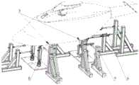
图1为本发明总体结构示意图(右侧视图)。Figure 1 is a schematic diagram of the overall structure of the present invention (right side view).
图2为本发明总体结构示意图(左侧视图)。Fig. 2 is a schematic diagram of the overall structure of the present invention (left side view).
图3为本发明Z向约束组件1结构示意图。FIG. 3 is a schematic structural diagram of the Z-
图4为本发明X向约束组件2结构示意图。FIG. 4 is a schematic structural diagram of the
其中,1-Z向约束组件;1a-转接件;1b-承载梁;1c-球形接头;1d-端盖;1e-球形底座;1f-六分量力传感器;1g-横向主动载荷加载接头;1h-Y向主动载荷加载接头;2-X向约束组件;2a-转接头;2b-力传感器;2c-螺杆;2d-安装座;2e-三角立柱;3-Y向约束组件;4-约束点载荷Fx加载装置;5-起落架限位点载荷Fz、Fy加载装置;6-起落架限位点载荷Fx加载装置;7-安装板;8-前约束点载荷Fy加载装置;9-后约束点载荷Fy加载装置。Among them, 1-Z direction restraint assembly; 1a-transition piece; 1b-loading beam; 1c-spherical joint; 1d-end cover; 1e-spherical base; 1f-six-component force sensor; 1g-transverse active load loading joint; 1h-active load joint in Y direction; 2-restraint component in X direction; 2a-transfer joint; 2b-force sensor; 2c-screw; 2d-mounting seat; Point load Fx loading device; 5- landing gear limit point load Fz, Fy loading device; 6- landing gear limit point load Fx loading device; 7- mounting plate; 8- front restraint point load Fy loading device; 9- rear Constrained point load Fy loading device.
具体实施方式Detailed ways
下面结合附图对本发明做进一步详细描述,参阅图1至图4。The present invention will be described in further detail below in conjunction with the accompanying drawings, referring to Fig. 1 to Fig. 4 .
一种直升机全机静力试验约束装置,如图1所示,包括:A helicopter whole machine static test restraint device, as shown in Figure 1, comprising:
Z向约束组件1,设置在安装板7的安装面上,数量为3个,分别与试验机3个起落架安装点联接,用于约束试验机沿Z轴平动、俯仰、滚转自由度。安装板7固定在承力地轨上。The Z-
Z向约束组件1的组成:转接件1a在最上端,与试验机起落架安装点联接;承载梁1b是由型材和钢板焊接而成的梁;球形接头1c在承载梁1b下部,与端盖1d、球形底座1e装配后,球形接头1c可沿球心自由转动;六分量力传感器1f在Z向约束组件1的最下端,与球形底座1e和安装板7联接。转接件1a下端的螺纹为右旋螺纹,球形接头1c的螺纹为左旋螺纹,可实现Z向约束组件1的长短调节。The composition of the Z-direction restraint assembly 1: the
X向约束组件2,设置在试验机后部,数量为1个,与试验机起落架后中安装点联接,用于约束试验机沿X轴平动的自由度。X向约束组件2固定在承力地轨上。The
X向约束组件2的组成:转接头2a是一组单双叉接头,一端与试验机起落架后中安装点联接,另一端与力传感器2b联接;螺杆2c的两端分别是左旋和右旋内螺纹,通过旋转螺杆2c可实现调整X向约束组件2长度的功能;安装座2d是焊接结构的支座,联接在三角立柱2e上;三角立柱2e固定在承力地轨上。The composition of the X-direction restraint assembly 2: the
Y向约束组件3,设置在试验机左侧,数量为2个,分别与试验机左侧前后两个系留点联接,用于约束试验机沿Y轴平动、偏航自由度。Y向约束组件3固定在承力地轨上。The Y-
Y向约束组件3的组成与X向约束组件2的组成相似,采用转接头与试验机左侧的两个系留点联接,中间串联力传感器,两端具有左旋和右旋内螺纹的螺杆可实现长短调节,通过三角立柱固定在承力地轨上。The composition of the Y-
约束点横向主动载荷加载接头1g和约束点Y向主动载荷加载接头1h,是机加而成的加载接头,分别安装在承载梁1b和转接件1a上,可以使Z向约束组件1同时实现对约束点施加X向和Y向主动载荷的功能。The lateral active
如图1、图2所示,一种直升机全机静力试验约束装置,包括Z向约束组件1、X向约束组件2、Y向约束组件3。As shown in FIGS. 1 and 2 , a restraint device for a helicopter static test includes a Z-
如图3所示,所述Z向约束组件1是由型材和钢板焊接而成的承载梁1b、转接件1a、球形接头1c、六分量力传感器1f组合联接而成。试验时,将Z向约束组件1下端安装至固定在承力地轨的安装板7上,上端与机身起落架约束点联接,为试验机提供Z向约束。转接件1a下端的螺纹为右旋螺纹,球形接头1c的螺纹为左旋螺纹,可实现Z向约束组件1的长短调节,在试验机约束安装时可用于调整试验机水平。由于约束点X向和Y向主动载荷也要施加到Z向约束组件1上,故需将Z向约束组件1所承受的Z向力与其他方向的力分离开,避免测量结果耦合,采用六分量力传感器1f可以实现上述功能。Z向约束组件1的上下两端各有一个铰接点,形成二力杆结构,可保证约束点Z向载荷的准确测量。As shown in FIG. 3 , the Z-
如图4所示,所述X向约束组件2是由转接头2a、力传感器2b、螺杆2c、安装座2d、三角立柱2e组合联接而成。试验时,将转接头2a与试验机约束点相联接,将三角立柱2e固定在承力地轨上。X向约束组件的力传感器2b两端各有一个铰接点,形成二力杆结构,可保证约束点X向载荷的准确测量。As shown in FIG. 4 , the
Y向约束组件3的组成与X向约束组件2的组成相似。试验时,采用转接头与试验机左侧的两个系留点联接,中间串联力传感器,两端具有左旋和右旋内螺纹的螺杆可实现长短调节,通过三角立柱固定在承力地轨上。Y向约束组件3的力传感器两端各有一个铰接点,形成二力杆结构,可保证约束点Y向载荷的准确测量。The composition of the Y-
如图1、图2所示,试验时,试验机沿Z轴平动、俯仰、滚转自由度通过Z向约束组件1进行限制;试验机沿X轴平动自由度通过X向约束组件2进行限制;试验机沿Y轴平动、偏航自由度通过Y向约束组件3进行限制。试验机6个自由度、6个约束,试验机约束为静定约束。As shown in Figure 1 and Figure 2, during the test, the freedom of translation, pitch and roll of the testing machine along the Z axis is restricted by the Z-
试验机约束点的X向主动载荷通过约束点载荷Fx加载装置4施加到横向主动载荷加载接头1g上;左前、右前约束点的Y向主动载荷通过前约束点载荷Fy加载装置8施加到Y向主动载荷加载接头1h上;后中约束点的Y向主动载荷通过后约束点载荷Fy加载装置9施加到横向主动载荷加载接头1g上,解决了后中约束点Y向载荷与起落架限位点载荷Fz、Fy加载装置5、起落架限位点载荷Fx加载装置6的干涉问题。The X-direction active load of the restraint point of the testing machine is applied to the lateral active load loading joint 1g through the restraint point load
本发明提供一种针对直升机全机静力试验的静定约束装置,可有效解决悬吊约束协调加载过程中试验机姿态变化的问题,同时,还可实现约束点被动载荷监控、约束点其他方向主动载荷的加载功能。The invention provides a statically determinate restraint device for the static test of the whole helicopter, which can effectively solve the problem of attitude change of the test machine during the coordinated loading process of the suspension restraint, and at the same time, it can also realize the passive load monitoring of the restraint point and other directions of the restraint point. Loading function for active loads.
Claims (8)
Priority Applications (1)
| Application Number | Priority Date | Filing Date | Title |
|---|---|---|---|
| CN202211582469.1ACN115901307A (en) | 2022-12-09 | 2022-12-09 | A restraint device for helicopter static test |
Applications Claiming Priority (1)
| Application Number | Priority Date | Filing Date | Title |
|---|---|---|---|
| CN202211582469.1ACN115901307A (en) | 2022-12-09 | 2022-12-09 | A restraint device for helicopter static test |
Publications (1)
| Publication Number | Publication Date |
|---|---|
| CN115901307Atrue CN115901307A (en) | 2023-04-04 |
Family
ID=86494667
Family Applications (1)
| Application Number | Title | Priority Date | Filing Date |
|---|---|---|---|
| CN202211582469.1APendingCN115901307A (en) | 2022-12-09 | 2022-12-09 | A restraint device for helicopter static test |
Country Status (1)
| Country | Link |
|---|---|
| CN (1) | CN115901307A (en) |
Cited By (2)
| Publication number | Priority date | Publication date | Assignee | Title |
|---|---|---|---|---|
| CN119503150A (en)* | 2024-10-27 | 2025-02-25 | 中国航空工业集团公司西安飞机设计研究所 | A method for supporting a full-machine static testing machine |
| CN119509956A (en)* | 2025-01-20 | 2025-02-25 | 辽宁通用航空研究院 | Aircraft energy storage equipment installation structure strength test device and test method |
- 2022
- 2022-12-09CNCN202211582469.1Apatent/CN115901307A/enactivePending
Cited By (2)
| Publication number | Priority date | Publication date | Assignee | Title |
|---|---|---|---|---|
| CN119503150A (en)* | 2024-10-27 | 2025-02-25 | 中国航空工业集团公司西安飞机设计研究所 | A method for supporting a full-machine static testing machine |
| CN119509956A (en)* | 2025-01-20 | 2025-02-25 | 辽宁通用航空研究院 | Aircraft energy storage equipment installation structure strength test device and test method |
Similar Documents
| Publication | Publication Date | Title |
|---|---|---|
| CN111169653B (en) | Hinge point force testing device of nose landing gear and load calibration method | |
| CN115901307A (en) | A restraint device for helicopter static test | |
| CN101726401B (en) | Scale measuring device for pitching dynamic derivative experiment | |
| CN105606357B (en) | A kind of aircraft test of static strength loading device | |
| CN205785839U (en) | Body in white bending stiffness test platform | |
| CN105651495B (en) | Swing arm class part durability degree test-bed | |
| CN204038998U (en) | A kind of engineering truck and leveling turntable device thereof | |
| CN106862908B (en) | A kind of full-automatic assembly interconnection method based on air flotation technology | |
| CN113588251B (en) | Simulation static test device and method for cylindrical cabin section wall plate structure | |
| CN105571813A (en) | Wind tunnel balance single-vector calibration loading mechanism | |
| CN204202864U (en) | Swing arm class part durability degree test-bed | |
| US4798088A (en) | Vehicle restraint system | |
| CN117602096B (en) | A high performance machine wheel shaft fatigue test device and test method thereof | |
| CN111693313A (en) | Large-load two-axis inclination and swing test system | |
| CN114427963B (en) | A high-size and large-load adjustable load-bearing platform and test method for static test | |
| CN115806057A (en) | Drop test bed and dynamic calibration method for undercarriage load measurement in load test flight | |
| CN108528758A (en) | General-purpose aircraft mechanical property testing system | |
| CN113340711A (en) | Reinforced wallboard static fatigue load application test device | |
| CN114739684A (en) | Test device and test method for front subframe bench | |
| CN215338839U (en) | A side deflection loading roll-over device for aircraft wheel fatigue test | |
| CN215048182U (en) | Double-shaft rocker arm hanging device for zero-gravity unfolding of large space mechanism | |
| CN105115685B (en) | Car body mass center test macro and method based on vehicle vibration test platform | |
| CN113109170A (en) | Composite material long beam strength test device | |
| CN116625720B (en) | Aviation seat test device and test method | |
| CN116990047A (en) | Suspension system test bed and method |
Legal Events
| Date | Code | Title | Description |
|---|---|---|---|
| PB01 | Publication | ||
| PB01 | Publication | ||
| SE01 | Entry into force of request for substantive examination | ||
| SE01 | Entry into force of request for substantive examination |