CN115899492A - display device - Google Patents
display deviceDownload PDFInfo
- Publication number
- CN115899492A CN115899492ACN202210031583.9ACN202210031583ACN115899492ACN 115899492 ACN115899492 ACN 115899492ACN 202210031583 ACN202210031583 ACN 202210031583ACN 115899492 ACN115899492 ACN 115899492A
- Authority
- CN
- China
- Prior art keywords
- screen body
- positioning holes
- base
- display device
- connecting arm
- Prior art date
- Legal status (The legal status is an assumption and is not a legal conclusion. Google has not performed a legal analysis and makes no representation as to the accuracy of the status listed.)
- Pending
Links
Images


Classifications
- F—MECHANICAL ENGINEERING; LIGHTING; HEATING; WEAPONS; BLASTING
- F16—ENGINEERING ELEMENTS AND UNITS; GENERAL MEASURES FOR PRODUCING AND MAINTAINING EFFECTIVE FUNCTIONING OF MACHINES OR INSTALLATIONS; THERMAL INSULATION IN GENERAL
- F16M—FRAMES, CASINGS OR BEDS OF ENGINES, MACHINES OR APPARATUS, NOT SPECIFIC TO ENGINES, MACHINES OR APPARATUS PROVIDED FOR ELSEWHERE; STANDS; SUPPORTS
- F16M11/00—Stands or trestles as supports for apparatus or articles placed thereon ; Stands for scientific apparatus such as gravitational force meters
- F16M11/02—Heads
- F16M11/04—Means for attachment of apparatus; Means allowing adjustment of the apparatus relatively to the stand
- F16M11/06—Means for attachment of apparatus; Means allowing adjustment of the apparatus relatively to the stand allowing pivoting
- F16M11/08—Means for attachment of apparatus; Means allowing adjustment of the apparatus relatively to the stand allowing pivoting around a vertical axis, e.g. panoramic heads
- G—PHYSICS
- G06—COMPUTING OR CALCULATING; COUNTING
- G06F—ELECTRIC DIGITAL DATA PROCESSING
- G06F1/00—Details not covered by groups G06F3/00 - G06F13/00 and G06F21/00
- G06F1/16—Constructional details or arrangements
- G06F1/1601—Constructional details related to the housing of computer displays, e.g. of CRT monitors, of flat displays
- G06F1/1607—Arrangements to support accessories mechanically attached to the display housing
- F—MECHANICAL ENGINEERING; LIGHTING; HEATING; WEAPONS; BLASTING
- F16—ENGINEERING ELEMENTS AND UNITS; GENERAL MEASURES FOR PRODUCING AND MAINTAINING EFFECTIVE FUNCTIONING OF MACHINES OR INSTALLATIONS; THERMAL INSULATION IN GENERAL
- F16M—FRAMES, CASINGS OR BEDS OF ENGINES, MACHINES OR APPARATUS, NOT SPECIFIC TO ENGINES, MACHINES OR APPARATUS PROVIDED FOR ELSEWHERE; STANDS; SUPPORTS
- F16M11/00—Stands or trestles as supports for apparatus or articles placed thereon ; Stands for scientific apparatus such as gravitational force meters
- F16M11/02—Heads
- F16M11/04—Means for attachment of apparatus; Means allowing adjustment of the apparatus relatively to the stand
- F16M11/043—Allowing translations
- F16M11/046—Allowing translations adapted to upward-downward translation movement
- F—MECHANICAL ENGINEERING; LIGHTING; HEATING; WEAPONS; BLASTING
- F16—ENGINEERING ELEMENTS AND UNITS; GENERAL MEASURES FOR PRODUCING AND MAINTAINING EFFECTIVE FUNCTIONING OF MACHINES OR INSTALLATIONS; THERMAL INSULATION IN GENERAL
- F16M—FRAMES, CASINGS OR BEDS OF ENGINES, MACHINES OR APPARATUS, NOT SPECIFIC TO ENGINES, MACHINES OR APPARATUS PROVIDED FOR ELSEWHERE; STANDS; SUPPORTS
- F16M11/00—Stands or trestles as supports for apparatus or articles placed thereon ; Stands for scientific apparatus such as gravitational force meters
- F16M11/20—Undercarriages with or without wheels
- F16M11/2007—Undercarriages with or without wheels comprising means allowing pivoting adjustment
- F16M11/2021—Undercarriages with or without wheels comprising means allowing pivoting adjustment around a horizontal axis
- G—PHYSICS
- G06—COMPUTING OR CALCULATING; COUNTING
- G06F—ELECTRIC DIGITAL DATA PROCESSING
- G06F1/00—Details not covered by groups G06F3/00 - G06F13/00 and G06F21/00
- G06F1/16—Constructional details or arrangements
- G06F1/1601—Constructional details related to the housing of computer displays, e.g. of CRT monitors, of flat displays
- G—PHYSICS
- G07—CHECKING-DEVICES
- G07G—REGISTERING THE RECEIPT OF CASH, VALUABLES, OR TOKENS
- G07G1/00—Cash registers
- G07G1/0018—Constructional details, e.g. of drawer, printing means, input means
- G—PHYSICS
- G07—CHECKING-DEVICES
- G07G—REGISTERING THE RECEIPT OF CASH, VALUABLES, OR TOKENS
- G07G1/00—Cash registers
- G07G1/01—Details for indicating
- F—MECHANICAL ENGINEERING; LIGHTING; HEATING; WEAPONS; BLASTING
- F16—ENGINEERING ELEMENTS AND UNITS; GENERAL MEASURES FOR PRODUCING AND MAINTAINING EFFECTIVE FUNCTIONING OF MACHINES OR INSTALLATIONS; THERMAL INSULATION IN GENERAL
- F16M—FRAMES, CASINGS OR BEDS OF ENGINES, MACHINES OR APPARATUS, NOT SPECIFIC TO ENGINES, MACHINES OR APPARATUS PROVIDED FOR ELSEWHERE; STANDS; SUPPORTS
- F16M2200/00—Details of stands or supports
- F16M2200/08—Foot or support base
- G—PHYSICS
- G06—COMPUTING OR CALCULATING; COUNTING
- G06F—ELECTRIC DIGITAL DATA PROCESSING
- G06F2200/00—Indexing scheme relating to G06F1/04 - G06F1/32
- G06F2200/16—Indexing scheme relating to G06F1/16 - G06F1/18
- G06F2200/161—Indexing scheme relating to constructional details of the monitor
- G06F2200/1612—Flat panel monitor
- G—PHYSICS
- G06—COMPUTING OR CALCULATING; COUNTING
- G06F—ELECTRIC DIGITAL DATA PROCESSING
- G06F2200/00—Indexing scheme relating to G06F1/04 - G06F1/32
- G06F2200/16—Indexing scheme relating to G06F1/16 - G06F1/18
- G06F2200/161—Indexing scheme relating to constructional details of the monitor
- G06F2200/1614—Image rotation following screen orientation, e.g. switching from landscape to portrait mode
- G—PHYSICS
- G06—COMPUTING OR CALCULATING; COUNTING
- G06F—ELECTRIC DIGITAL DATA PROCESSING
- G06F2200/00—Indexing scheme relating to G06F1/04 - G06F1/32
- G06F2200/16—Indexing scheme relating to G06F1/16 - G06F1/18
- G06F2200/163—Indexing scheme relating to constructional details of the computer
- G06F2200/1631—Panel PC, e.g. single housing hosting PC and display panel
Landscapes
- Engineering & Computer Science (AREA)
- General Engineering & Computer Science (AREA)
- Theoretical Computer Science (AREA)
- Physics & Mathematics (AREA)
- General Physics & Mathematics (AREA)
- Mechanical Engineering (AREA)
- Computer Hardware Design (AREA)
- Human Computer Interaction (AREA)
- Devices For Indicating Variable Information By Combining Individual Elements (AREA)
- Vehicle Body Suspensions (AREA)
- Diaphragms For Electromechanical Transducers (AREA)
- Measuring Pulse, Heart Rate, Blood Pressure Or Blood Flow (AREA)
Abstract
Description
Translated fromChinese技术领域technical field
本发明是有关于一种显示装置,并且更具体地,是有关于一种POS(Point ofSale,销售点)系统的显示装置。The present invention relates to a display device, and more particularly, to a display device for a POS (Point of Sale, point of sale) system.
背景技术Background technique
目前应用在商店、卖场、柜台或银行的POS系统,通常会与收款机搭配使用。现有的POS系统包括供用户点选的触控式显示装置、立于平面上的基座、及用以连接显示装置与基座的连接构件。现有的POS系统的显示屏幕及主机在组装及拆卸时都较为复杂,因此,维修人员想要进行显示屏幕或主机的维修或更换时,需耗费较多的工时进行拆卸及组装。此外,由于现有的POS系统在显示屏幕安装时有直式或横式的限制,一旦选定直式或横式,就难以更改,使得制造商在生产备货及库存管理上都很不方便。POS systems currently used in stores, stores, counters or banks are usually used in conjunction with cash registers. The existing POS system includes a touch-sensitive display device for users to click, a base standing on a plane, and a connecting member for connecting the display device and the base. The display screen and host of the existing POS system are relatively complicated to assemble and disassemble. Therefore, when maintenance personnel want to repair or replace the display screen or host, it takes a lot of man-hours to disassemble and assemble. In addition, because the existing POS system has the limitation of vertical or horizontal display screen installation, once the vertical or horizontal display is selected, it is difficult to change it, which makes it very inconvenient for manufacturers to prepare goods and manage inventory.
基于以上原因,有必要提供一种可以解决现有技术缺失的方案。Based on the above reasons, it is necessary to provide a solution that can solve the deficiency in the prior art.
发明内容Contents of the invention
发明要解决的技术问题The technical problem to be solved by the invention
有鉴于上述现有技术之问题,本发明的目的在于提供一种结构简易的显示装置,以达到可灵活调整屏幕的组装形态。In view of the above-mentioned problems in the prior art, the object of the present invention is to provide a display device with a simple structure, so as to achieve flexible adjustment of the assembled form of the screen.
用于解决技术问题的技术方案Technical solutions for technical problems
本发明提出一种显示装置,包括:屏幕本体、第一角度调节机构、连接臂、第二角度调节机构及基座;其中,上述屏幕本体设有第一组定位孔及第二组定位孔,上述第一组定位孔对应于上述屏幕本体的纵向形态且上述第二组定位孔对应于上述屏幕本体的横向形态,上述第一角度调节机构可选择性地通过上述第一组定位孔或上述第二组定位孔连接到上述屏幕本体,使得上述屏幕本体直立或横放;上述第一角度调节机构与上述连接臂枢接,使得上述屏幕本体与上述连接臂相对彼此在上述第一角度调节机构的周向方向上是可旋转的;上述第二角度调节机构与上述连接臂及上述基座枢接,使得上述连接臂与上述基座相对彼此在上述第二角度调节机构的周向方向上是可旋转的。The present invention proposes a display device, including: a screen body, a first angle adjustment mechanism, a connecting arm, a second angle adjustment mechanism, and a base; wherein, the screen body is provided with a first set of positioning holes and a second set of positioning holes, The above-mentioned first group of positioning holes corresponds to the longitudinal form of the above-mentioned screen body and the above-mentioned second group of positioning holes corresponds to the horizontal form of the above-mentioned screen body. The above-mentioned first angle adjustment mechanism can selectively pass through the above-mentioned first group of positioning holes or the above-mentioned second Two sets of positioning holes are connected to the above-mentioned screen body, so that the above-mentioned screen body is upright or placed horizontally; the above-mentioned first angle adjustment mechanism is pivotally connected with the above-mentioned connecting arm, so that the above-mentioned screen body and the above-mentioned connecting arm are relative to each other in the position of the above-mentioned first angle adjustment mechanism. It is rotatable in the circumferential direction; the above-mentioned second angle adjustment mechanism is pivotally connected with the above-mentioned connecting arm and the above-mentioned base, so that the above-mentioned connecting arm and the above-mentioned base are relatively rotatable in the circumferential direction of the above-mentioned second angle adjusting mechanism rotating.
于本发明之一实施例中,上述第一角度调节机构由一对枢接件组成,上述枢接件包括枢接端及固定端。In an embodiment of the present invention, the above-mentioned first angle adjustment mechanism is composed of a pair of pivotal joints, and the above-mentioned pivotal joints include a pivotal end and a fixed end.
于本发明之一实施例中,上述第二角度调节机构包括枢接轴本体及形成在上述枢接轴本体两侧的枢接轴连接端。In an embodiment of the present invention, the second angle adjustment mechanism includes a pivot shaft body and pivot shaft connection ends formed on both sides of the pivot shaft body.
于本发明之一实施例中,上述连接臂的一端对应于上述枢接端设有第一枢接部,且上述连接臂的另一端对应于上述枢接轴本体设有第二枢接部。In an embodiment of the present invention, one end of the connection arm is provided with a first pivot portion corresponding to the pivot end, and the other end of the connection arm is provided with a second pivot portion corresponding to the pivot shaft body.
于本发明之一实施例中,上述基座的一侧对应于上述枢接轴连接端设有第三枢接部。In an embodiment of the present invention, one side of the base is provided with a third pivot portion corresponding to the connecting end of the pivot shaft.
于本发明之一实施例中,上述基座的另一侧设置外连接部。In an embodiment of the present invention, the other side of the base is provided with an external connection portion.
于本发明之一实施例中,上述显示装置还包括底座,上述基座通过上述外连接部与上述底座连接。In an embodiment of the present invention, the display device further includes a base, and the base is connected to the base through the external connecting portion.
发明效果Invention effect
本发明能够提供一种结构简易的显示装置,以达到可灵活调整屏幕的组装形态。The present invention can provide a display device with a simple structure to achieve flexible adjustment of the assembled form of the screen.
附图说明Description of drawings
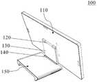
图1是本发明的显示装置的纵向形态的立体图。FIG. 1 is a perspective view of a vertical form of a display device of the present invention.
图2是本发明的显示装置的横向形态的立体图。Fig. 2 is a perspective view of a display device of the present invention in a lateral form.
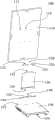
图3是表示本发明的显示装置的纵向形态的分解图。Fig. 3 is an exploded view showing the vertical configuration of the display device of the present invention.
图4是表示本发明的显示装置的横向形态的分解图。Fig. 4 is an exploded view showing a horizontal form of the display device of the present invention.
图5是本发明的显示装置的另一实施例的横向形态的立体图。FIG. 5 is a perspective view of another embodiment of the display device of the present invention in a horizontal form.
图6及图7是本发明的显示装置的另一实施例的纵向形态的立体图。6 and 7 are perspective views of another embodiment of the display device in the vertical direction according to the present invention.
附图标记说明Explanation of reference signs
100:显示装置100: display device
110:屏幕本体110: screen body
112:第一组定位孔112: The first set of positioning holes
114:第二组定位孔114: The second set of positioning holes
120:第一角度调节机构120: First angle adjustment mechanism
122:枢接件122: Pivot piece
124:枢接端124: Pivot end
126:固定端126: fixed end
130:连接臂130: connecting arm
132:第一枢接部132: First pivot joint
134:第二枢接部134: Second pivot joint
140:第二角度调节机构140: second angle adjustment mechanism
142:枢接轴本体142: Pivot shaft body
144:枢接轴连接端144: Pivot shaft connection end
150:基座150: Base
152:第三枢接部152: The third pivot joint
154:外连接部154: External connection part
160:底座160: base
具体实施方式Detailed ways
为了让本发明的上述及其他目的、特征、优点能更明显易懂,下文将例举本发明优选实施例,并配合附图,详细说明如下。In order to make the above and other objects, features and advantages of the present invention more comprehensible, preferred embodiments of the present invention will be exemplified below and described in detail in conjunction with the accompanying drawings.
首先,请参考图1及图2。图1是本发明的显示装置的纵向形态的立体图。图2是本发明的显示装置的横向形态的立体图。在本实施例中,本发明的显示装置100包括屏幕本体110、第一角度调节机构120、连接臂130、第二角度调节机构140及基座150。在图1中,屏幕本体110设置成纵向形态,亦即直立,在其他条件下,屏幕本体110可设置成横向形态,亦即横放(如图2所示)。在本实施例中,基座150调整成水平形态,基座150放置在一个承载平面(例如桌面)上,此时基座150成为承载屏幕本体110及连接臂130的基础,使得屏幕本体110维持稳定。First, please refer to Figure 1 and Figure 2. FIG. 1 is a perspective view of a vertical form of a display device of the present invention. Fig. 2 is a perspective view of a display device of the present invention in a lateral form. In this embodiment, the
请再参考图3及图4。图3是表示本发明的显示装置的纵向形态的分解图。图4是表示本发明的显示装置的横向形态的分解图。图3与图4的显示装置差异在于屏幕本体110的直立与横放。屏幕本体110设有第一组定位孔112及第二组定位孔114。在本实施例中,第一组定位孔112对应于屏幕本体110的纵向形态且第二组定位孔114对应于屏幕本体110的横向形态,但不限于此。更具体地,当屏幕本体110使用第一组定位孔112进行组装时,屏幕本体110会设置成直立,当屏幕本体110使用第二组定位孔114进行组装时,屏幕本体110会设置成横放。在本实施例中,每一组定位孔由两对定位孔组成,每一对定位孔具有两个定位孔,也就是说,一组定位孔等于四个定位孔,但不限于此。在本实施例中,第一角度调节机构120由一对枢接件122组成,枢接件122包括枢接端124及固定端126。第二角度调节机构140包括枢接轴本体142及形成在枢接轴本体142两侧的枢接轴连接端144。连接臂130的一端对应于枢接端124设有第一枢接部132,且连接臂130的另一端对应于枢接轴本体142设有第二枢接部134。基座150的一侧对应于枢接轴连接端144则设有第三枢接部152。Please refer to FIG. 3 and FIG. 4 again. Fig. 3 is an exploded view showing the vertical configuration of the display device of the present invention. Fig. 4 is an exploded view showing a horizontal form of the display device of the present invention. The difference between the display devices in FIG. 3 and FIG. 4 lies in the upright and horizontal orientation of the
在本实施例中,第一角度调节机构120可选择性地通过第一组定位孔112或第二组定位孔114连接到屏幕本体110,使得屏幕本体110呈现纵向形态(即直立)或横向形态(即横放)。更具体地,第一角度调节机构120的枢接件122的固定端126连接到屏幕本体110的第一组定位孔112时,屏幕本体110呈现直立(如图1与图3所示)。第一角度调节机构120的枢接件122的固定端126连接到屏幕本体110的第二组定位孔114时,屏幕本体110呈现横放(如图2与图4所示)。在本实施例中,固定端126的面向屏幕本体110那一侧设有对应于第一组定位孔112或第二组定位孔114的孔位。通过螺丝可以将第一组定位孔112或第二组定位孔114与固定端126的孔位锁附在一起。由于上述的定位孔与固定端的连接结构,更容易灵活调整屏幕本体110为直立或横放。In this embodiment, the first
在本实施例中,第一角度调节机构120与连接臂130枢接,使得屏幕本体110与连接臂130相对彼此在第一角度调节机构120的周向方向上是可旋转的。更具体地,第一角度调节机构120的枢接件122的枢接端124与连接臂130的第一枢接部132枢接(在此实施例中是将两个枢接件122从两侧分别插入第一枢接部132)。如此,枢接件122成为屏幕本体110及连接臂130的轴心,使得屏幕本体110及连接臂130可以在轴心的周向上进行旋转。在此结构下,屏幕本体110可以进行俯仰角度的调整。第二角度调节机构140与连接臂130及基座150枢接,使得连接臂130与基座150相对彼此在第二角度调节机构140的周向方向上是可旋转的。在本实施例中,第二角度调节机构140是一种枢接轴。更具体地,第二角度调节机构140的枢接轴本体142与连接臂130的第二枢接部134枢接,并且第二角度调节机构140的枢接轴连接端144与基座150的第三枢接部152枢接(在此实施例中是将枢接轴本体142套入第二枢接部134,且将枢接轴连接端144插入到第三枢接部152)。如此,第二角度调节机构140成为连接臂130及基座150的轴心,使得连接臂130及基座150可以在轴心的周向上进行旋转。在此结构下,基座150可以调整成水平或垂直等各种角度。由于上述的连接结构,有助于更快速拆卸及组装屏幕本体110、连接臂130及基座150。In this embodiment, the first
请参考图5,图5是本发明的显示装置的另一实施例的横向形态的立体图。在此实施例中,显示装置100还包括底座160。底座160与基座150通过外连接部154(未显示于图5,但显示于图3及图4)相连接。在此实施例中,基座150调整成垂直的状态,底座160平放在一个承载平面(例如桌面)上,此时底座160成为承载屏幕本体110及连接臂130的基础,使得屏幕本体110维持稳定,而基座150形成为连接臂130的延伸而增加屏幕的高度。Please refer to FIG. 5 . FIG. 5 is a perspective view of another embodiment of the display device of the present invention in a horizontal form. In this embodiment, the
请同时参考图6与图7。图6及图7是本发明的显示装置的另一实施例的纵向形态的立体图。在一实施例中,第一组定位孔112还可以包括上方定位孔(位于屏幕本体110的较上方位置,请一并参考图3)及下方定位孔(位于屏幕本体110的较下方位置)。如图6所示,当连接臂130通过第一组定位孔112的较下方定位孔连接到屏幕本体110时,屏幕本体110高度被调升。同样地,如图7所示,当连接臂130通过第一组定位孔112的较上方定位孔连接到屏幕本体110时,屏幕本体110高度被调降。Please refer to Figure 6 and Figure 7 at the same time. 6 and 7 are perspective views of another embodiment of the display device in the vertical direction according to the present invention. In one embodiment, the first set of
综上所述,有别于现有的显示装置,本发明的显示装置提供灵活调整屏幕的功能,以及达到方便拆装显示装置的效果。To sum up, different from the existing display device, the display device of the present invention provides the function of flexibly adjusting the screen, and achieves the effect of convenient disassembly and assembly of the display device.
以上所述仅为举例,而并非限制性的。任何未脱离本发明的精神与范畴,而对其进行的等效修改或变更,均应包含于后附的申请专利范围中。The foregoing are examples only, not limiting. Any equivalent modification or change made without departing from the spirit and scope of the present invention shall be included in the scope of the appended patent application.
Claims (7)
Translated fromChineseApplications Claiming Priority (2)
| Application Number | Priority Date | Filing Date | Title |
|---|---|---|---|
| TW110128454 | 2021-08-03 | ||
| TW110128454ATWI782648B (en) | 2021-08-03 | 2021-08-03 | Display device |
Publications (1)
| Publication Number | Publication Date |
|---|---|
| CN115899492Atrue CN115899492A (en) | 2023-04-04 |
Family
ID=78695514
Family Applications (1)
| Application Number | Title | Priority Date | Filing Date |
|---|---|---|---|
| CN202210031583.9APendingCN115899492A (en) | 2021-08-03 | 2022-01-12 | display device |
Country Status (5)
| Country | Link |
|---|---|
| US (1) | US20230038139A1 (en) |
| EP (1) | EP4130932A1 (en) |
| CN (1) | CN115899492A (en) |
| AU (1) | AU2021290262A1 (en) |
| TW (1) | TWI782648B (en) |
Citations (5)
| Publication number | Priority date | Publication date | Assignee | Title |
|---|---|---|---|---|
| CN102478142A (en)* | 2010-11-30 | 2012-05-30 | 富泰华工业(深圳)有限公司 | Supporting mechanism and display device adopting same |
| CN203857230U (en)* | 2014-05-13 | 2014-10-01 | 联想(北京)有限公司 | Base |
| CN104260674A (en)* | 2014-09-19 | 2015-01-07 | 奇瑞汽车股份有限公司 | Angle-adjustable vehicle-mounted display frame |
| CN105546303A (en)* | 2015-12-11 | 2016-05-04 | 中国电子科技集团公司第四十一研究所 | Front universal displayer support for shelving |
| CN207852206U (en)* | 2018-01-31 | 2018-09-11 | 广东佳的美智能科技有限公司 | A kind of support construction of display terminal |
Family Cites Families (4)
| Publication number | Priority date | Publication date | Assignee | Title |
|---|---|---|---|---|
| TW378830U (en)* | 1997-08-09 | 2000-01-01 | Mitac Int Corp | Sliding and revolving structure for LCD screens |
| KR100482007B1 (en)* | 2002-09-28 | 2005-04-13 | 삼성전자주식회사 | Monitor |
| TWI519727B (en)* | 2013-01-16 | 2016-02-01 | 建碁股份有限公司 | Support arm |
| CN203718318U (en)* | 2014-01-02 | 2014-07-16 | 兆利科技工业股份有限公司 | Support structure |
- 2021
- 2021-08-03TWTW110128454Apatent/TWI782648B/enactive
- 2021-11-17EPEP21208873.6Apatent/EP4130932A1/ennot_activeWithdrawn
- 2021-12-21AUAU2021290262Apatent/AU2021290262A1/enactivePending
- 2021-12-22USUS17/558,916patent/US20230038139A1/ennot_activeAbandoned
- 2022
- 2022-01-12CNCN202210031583.9Apatent/CN115899492A/enactivePending
Patent Citations (5)
| Publication number | Priority date | Publication date | Assignee | Title |
|---|---|---|---|---|
| CN102478142A (en)* | 2010-11-30 | 2012-05-30 | 富泰华工业(深圳)有限公司 | Supporting mechanism and display device adopting same |
| CN203857230U (en)* | 2014-05-13 | 2014-10-01 | 联想(北京)有限公司 | Base |
| CN104260674A (en)* | 2014-09-19 | 2015-01-07 | 奇瑞汽车股份有限公司 | Angle-adjustable vehicle-mounted display frame |
| CN105546303A (en)* | 2015-12-11 | 2016-05-04 | 中国电子科技集团公司第四十一研究所 | Front universal displayer support for shelving |
| CN207852206U (en)* | 2018-01-31 | 2018-09-11 | 广东佳的美智能科技有限公司 | A kind of support construction of display terminal |
Also Published As
| Publication number | Publication date |
|---|---|
| US20230038139A1 (en) | 2023-02-09 |
| TWI782648B (en) | 2022-11-01 |
| AU2021290262A1 (en) | 2023-02-23 |
| TW202307358A (en) | 2023-02-16 |
| EP4130932A1 (en) | 2023-02-08 |
Similar Documents
| Publication | Publication Date | Title |
|---|---|---|
| US7986517B2 (en) | Notebook computer | |
| TWI221954B (en) | Flat panel display | |
| US7623342B2 (en) | Support structure for two or more flat panel display devices | |
| CN101669080B (en) | Adjustable display | |
| TWI434643B (en) | Electronic device with supporting stand | |
| US8608119B2 (en) | Display stand | |
| US20120223194A1 (en) | Support stand for electronic device | |
| US7980737B2 (en) | Electronic device support | |
| CN114466092A (en) | A rotating mechanism, support device and electronic equipment | |
| US20120170197A1 (en) | All in one computer | |
| CN114063330A (en) | Frame and back plate assembly, backlight module and display device | |
| TWI782648B (en) | Display device | |
| CN108962036B (en) | Foldable display device | |
| TWM654846U (en) | Monitor stand | |
| CN2922063Y (en) | screen support structure | |
| CN114613255B (en) | Rotating mechanisms, flexible display devices and electronic equipment | |
| CN114857439A (en) | Notebook three-screen linkage bracket | |
| US20120033362A1 (en) | Flat-panel display monitor | |
| CN206726724U (en) | Advertising display support and intelligent advertisement display systems | |
| CN208255764U (en) | A kind of visualization mixing type data reproducing device | |
| AU2020100104A4 (en) | Projector with arm supported fixing frame | |
| CN218094989U (en) | A new data display bracket structure | |
| CN2831343Y (en) | Support | |
| CN109899648A (en) | A kind of display screen mounting base and multi-screen support frame | |
| CN223295523U (en) | Split-screen electronic scale support structure and electronic scale thereof |
Legal Events
| Date | Code | Title | Description |
|---|---|---|---|
| PB01 | Publication | ||
| PB01 | Publication | ||
| SE01 | Entry into force of request for substantive examination | ||
| SE01 | Entry into force of request for substantive examination |