CN115887905A - Connector and method of manufacturing connector - Google Patents
Connector and method of manufacturing connectorDownload PDFInfo
- Publication number
- CN115887905A CN115887905ACN202310045849.XACN202310045849ACN115887905ACN 115887905 ACN115887905 ACN 115887905ACN 202310045849 ACN202310045849 ACN 202310045849ACN 115887905 ACN115887905 ACN 115887905A
- Authority
- CN
- China
- Prior art keywords
- connector
- tubing
- bore
- core pin
- tube
- Prior art date
- Legal status (The legal status is an assumption and is not a legal conclusion. Google has not performed a legal analysis and makes no representation as to the accuracy of the status listed.)
- Pending
Links
- 238000004519manufacturing processMethods0.000titleclaimsabstractdescription12
- 230000007423decreaseEffects0.000claimsabstractdescription5
- 239000000463materialSubstances0.000claimsdescription20
- 239000002904solventSubstances0.000claimsdescription19
- 238000000034methodMethods0.000claimsdescription10
- 230000001154acute effectEffects0.000claims1
- 239000012530fluidSubstances0.000description51
- 230000007246mechanismEffects0.000description16
- 238000001990intravenous administrationMethods0.000description14
- 230000014759maintenance of locationEffects0.000description7
- 239000007787solidSubstances0.000description7
- 238000007789sealingMethods0.000description5
- 238000000926separation methodMethods0.000description5
- 230000008901benefitEffects0.000description4
- 238000013461designMethods0.000description4
- 238000005516engineering processMethods0.000description4
- 230000001788irregularEffects0.000description4
- 230000036961partial effectEffects0.000description4
- 238000013459approachMethods0.000description3
- 238000001746injection mouldingMethods0.000description3
- 230000003247decreasing effectEffects0.000description2
- 239000007789gasSubstances0.000description2
- 238000001802infusionMethods0.000description2
- 230000004048modificationEffects0.000description2
- 238000012986modificationMethods0.000description2
- 238000000465mouldingMethods0.000description2
- 238000009428plumbingMethods0.000description2
- 230000008569processEffects0.000description2
- 238000007790scrapingMethods0.000description2
- 239000011800void materialSubstances0.000description2
- FAPWRFPIFSIZLT-UHFFFAOYSA-MSodium chlorideChemical compound[Na+].[Cl-]FAPWRFPIFSIZLT-UHFFFAOYSA-M0.000description1
- 230000004075alterationEffects0.000description1
- QVGXLLKOCUKJST-UHFFFAOYSA-Natomic oxygenChemical compound[O]QVGXLLKOCUKJST-UHFFFAOYSA-N0.000description1
- 230000000903blocking effectEffects0.000description1
- 239000008280bloodSubstances0.000description1
- 210000004369bloodAnatomy0.000description1
- 238000004891communicationMethods0.000description1
- 238000000502dialysisMethods0.000description1
- 238000005553drillingMethods0.000description1
- 230000002708enhancing effectEffects0.000description1
- 230000006870functionEffects0.000description1
- 238000001631haemodialysisMethods0.000description1
- 230000000322hemodialysisEffects0.000description1
- 238000003780insertionMethods0.000description1
- 230000037431insertionEffects0.000description1
- 230000000670limiting effectEffects0.000description1
- 239000007788liquidSubstances0.000description1
- 239000001301oxygenSubstances0.000description1
- 229910052760oxygenInorganic materials0.000description1
- 230000035515penetrationEffects0.000description1
- 230000002829reductive effectEffects0.000description1
- 230000000717retained effectEffects0.000description1
- 239000011780sodium chlorideSubstances0.000description1
- 230000007480spreadingEffects0.000description1
- 230000007704transitionEffects0.000description1
Images


Classifications
- A—HUMAN NECESSITIES
- A61—MEDICAL OR VETERINARY SCIENCE; HYGIENE
- A61M—DEVICES FOR INTRODUCING MEDIA INTO, OR ONTO, THE BODY; DEVICES FOR TRANSDUCING BODY MEDIA OR FOR TAKING MEDIA FROM THE BODY; DEVICES FOR PRODUCING OR ENDING SLEEP OR STUPOR
- A61M39/00—Tubes, tube connectors, tube couplings, valves, access sites or the like, specially adapted for medical use
- A61M39/10—Tube connectors; Tube couplings
- A61M39/1011—Locking means for securing connection; Additional tamper safeties
- A—HUMAN NECESSITIES
- A61—MEDICAL OR VETERINARY SCIENCE; HYGIENE
- A61M—DEVICES FOR INTRODUCING MEDIA INTO, OR ONTO, THE BODY; DEVICES FOR TRANSDUCING BODY MEDIA OR FOR TAKING MEDIA FROM THE BODY; DEVICES FOR PRODUCING OR ENDING SLEEP OR STUPOR
- A61M39/00—Tubes, tube connectors, tube couplings, valves, access sites or the like, specially adapted for medical use
- A61M39/10—Tube connectors; Tube couplings
- A61M39/12—Tube connectors; Tube couplings for joining a flexible tube to a rigid attachment
- A—HUMAN NECESSITIES
- A61—MEDICAL OR VETERINARY SCIENCE; HYGIENE
- A61M—DEVICES FOR INTRODUCING MEDIA INTO, OR ONTO, THE BODY; DEVICES FOR TRANSDUCING BODY MEDIA OR FOR TAKING MEDIA FROM THE BODY; DEVICES FOR PRODUCING OR ENDING SLEEP OR STUPOR
- A61M25/00—Catheters; Hollow probes
- A61M25/0021—Catheters; Hollow probes characterised by the form of the tubing
- A61M2025/0042—Microcatheters, cannula or the like having outside diameters around 1 mm or less
- A—HUMAN NECESSITIES
- A61—MEDICAL OR VETERINARY SCIENCE; HYGIENE
- A61M—DEVICES FOR INTRODUCING MEDIA INTO, OR ONTO, THE BODY; DEVICES FOR TRANSDUCING BODY MEDIA OR FOR TAKING MEDIA FROM THE BODY; DEVICES FOR PRODUCING OR ENDING SLEEP OR STUPOR
- A61M25/00—Catheters; Hollow probes
- A61M25/0097—Catheters; Hollow probes characterised by the hub
- B—PERFORMING OPERATIONS; TRANSPORTING
- B29—WORKING OF PLASTICS; WORKING OF SUBSTANCES IN A PLASTIC STATE IN GENERAL
- B29C—SHAPING OR JOINING OF PLASTICS; SHAPING OF MATERIAL IN A PLASTIC STATE, NOT OTHERWISE PROVIDED FOR; AFTER-TREATMENT OF THE SHAPED PRODUCTS, e.g. REPAIRING
- B29C45/00—Injection moulding, i.e. forcing the required volume of moulding material through a nozzle into a closed mould; Apparatus therefor
- B29C45/17—Component parts, details or accessories; Auxiliary operations
- B29C45/26—Moulds
- B29C45/2628—Moulds with mould parts forming holes in or through the moulded article, e.g. for bearing cages
- B—PERFORMING OPERATIONS; TRANSPORTING
- B29—WORKING OF PLASTICS; WORKING OF SUBSTANCES IN A PLASTIC STATE IN GENERAL
- B29C—SHAPING OR JOINING OF PLASTICS; SHAPING OF MATERIAL IN A PLASTIC STATE, NOT OTHERWISE PROVIDED FOR; AFTER-TREATMENT OF THE SHAPED PRODUCTS, e.g. REPAIRING
- B29C59/00—Surface shaping of articles, e.g. embossing; Apparatus therefor
- B29C59/02—Surface shaping of articles, e.g. embossing; Apparatus therefor by mechanical means, e.g. pressing
- B29C59/021—Surface shaping of articles, e.g. embossing; Apparatus therefor by mechanical means, e.g. pressing of profiled articles, e.g. hollow or tubular articles, beams
Landscapes
- Health & Medical Sciences (AREA)
- Heart & Thoracic Surgery (AREA)
- Pulmonology (AREA)
- Engineering & Computer Science (AREA)
- Anesthesiology (AREA)
- Biomedical Technology (AREA)
- Hematology (AREA)
- Life Sciences & Earth Sciences (AREA)
- Animal Behavior & Ethology (AREA)
- General Health & Medical Sciences (AREA)
- Public Health (AREA)
- Veterinary Medicine (AREA)
- Infusion, Injection, And Reservoir Apparatuses (AREA)
Abstract
Translated fromChinese
Description
Translated fromChinese本申请是申请日为2020年3月27日、申请号为202080042032.1(国际申请号为PCT/US2020/025279)、发明名称为“具有与轴向花键结合在一起的微孔管件保持袋的鲁尔件”的申请的分案申请。The application date is March 27, 2020, the application number is 202080042032.1 (the international application number is PCT/US2020/025279), and the invention name is "Luo The divisional application of the application of "Er file".
技术领域technical field
本公开总体上涉及医用连接器,并且更具体地说,涉及一种具有保持机构和密封机构的医用连接器,该保持机构用于防止与其联接的管件由于管件中流体的减少而与连接器脱离或分开,该密封机构用于防止流体在管件和连接器之间意外泄漏。The present disclosure relates generally to medical connectors, and more particularly, to a medical connector having a retention mechanism and a sealing mechanism for preventing a tubing coupled thereto from disengaging from the connector due to loss of fluid in the tubing Or separate, this sealing mechanism is used to prevent the accidental leakage of fluid between the fitting and the connector.
背景技术Background technique
在医用领域中,流体经常作为输液施用。容纳医用流体的容器(比如柔性静脉注射(IV)袋)通过一次性IV套件连接到输注装置(比如IV针),该一次性IV套件包含具有一个或更多个接头或连接器的管件。IV套件还可以具有中间端口或连接点,在这里可以连接额外的流体容器以引入或抽出流体。通过插入管件的内部中的一种或更多种形式的机械附接和结合(比如接头的内袋和管件的外表面之间的溶剂焊接),管件连接到接头或连接器。In the medical field, fluids are often administered as infusions. A container containing medical fluid, such as a flexible intravenous (IV) bag, is connected to an infusion set, such as an IV needle, through a disposable IV set comprising tubing with one or more fittings or connectors. IV sets may also have intermediate ports or connection points where additional fluid containers can be attached to introduce or withdraw fluids. The tubing is connected to the fitting or connector by one or more forms of mechanical attachment and bonding inserted into the interior of the fitting, such as a solvent weld between the inner pocket of the fitting and the outer surface of the fitting.
医用连接器广泛用于流体输送系统中,比如与静脉注射(IV)流体管线、血液通路、血液透析、腹膜透析、肠内喂养、药瓶通路等有关的流体输送系统。医用连接器通常可以连接两个流体管线或管件。Medical connectors are widely used in fluid delivery systems such as those associated with intravenous (IV) fluid lines, blood access, hemodialysis, peritoneal dialysis, enteral feeding, vial access, and the like. Medical connectors typically connect two fluid lines or fittings.
发明内容Contents of the invention
医用连接器可以是在其一端处接收流体管线或管件的中空管状结构。连接器为从管件进入的流体提供流动路径以从其相对端离开连接器。管件中流体的存在可以在管件的外表面和医用连接器的内表面之间产生气密密封。该密封可以防止管件与医用连接器分离。然而,当管件中没有流体或当管件中的流体量减少时,密封可能被削弱,并且管件可以容易与连接器分离,从而产生“自由流动”泄漏。A medical connector may be a hollow tubular structure that receives a fluid line or tubing at one end thereof. The connector provides a flow path for fluid entering from the tubing to exit the connector at its opposite end. The presence of fluid in the tubing can create a hermetic seal between the outer surface of the tubing and the inner surface of the medical connector. This seal prevents separation of the tubing from the medical connector. However, when there is no fluid in the fitting or when the amount of fluid in the fitting decreases, the seal can be weakened and the fitting can easily separate from the connector, creating a "free flow" leak.
此外,在使用微孔管件的情况下,用于结合的微孔管件的最小表面积对将微孔管件保持在连接器中提出了额外的挑战。Furthermore, where microbore tubing is used, the minimum surface area of the microbore tubing for bonding presents additional challenges to retaining the microbore tubing in the connector.
根据本公开的各种实施例,连接器包括主体,该主体具有管件部分、与管件部分轴向相对并且与其连接的鲁尔件部分、以及限定连接器的内孔的内圆周表面。内圆周表面在管件部分和鲁尔件部分之间轴向延伸,并且内孔与管件部分和鲁尔件部分流体连通。内圆周表面包括在连接器的管件部分中沿着内圆周表面的长度轴向延伸的多个花键。内圆周表面被配置成在联接构造中接合管件的外表面。在联接构造中,花键的边缘夹紧并且接合管件的外表面,以将管件保持在主体中。According to various embodiments of the present disclosure, a connector includes a body having a tubular portion, a luer portion axially opposite and connected to the tubular portion, and an inner circumferential surface defining an inner bore of the connector. The inner circumferential surface extends axially between the tube portion and the luer portion, and the inner bore is in fluid communication with the tube portion and the luer portion. The inner circumferential surface includes a plurality of splines extending axially along the length of the inner circumferential surface in the tubular portion of the connector. The inner circumferential surface is configured to engage the outer surface of the pipe in a coupled configuration. In the coupled configuration, the edges of the splines grip and engage the outer surface of the tubing to retain the tubing in the body.
根据本公开的各种实施例,连接器包括主体,该主体具有管件轮廓、与管件部分轴向相对并且与其连接的鲁尔件轮廓、介于鲁尔件轮廓和管件轮廓之间的限制件、以及至少在管件轮廓中限定内孔的内圆周表面。该限制件包括沿着鲁尔件轮廓的第一端、沿着管件轮廓的第二端以及从第二端轴向延伸的突出部,并且该突出部延伸到内孔中。内圆周表面被配置成在联接构造中接合管件的外表面。在联接构造中,突出部夹紧管件,以在限制件的第二端和管件之间形成密封。According to various embodiments of the present disclosure, a connector includes a body having a tubing profile, a luer profile axially opposite and connected to the tube portion, a restriction between the luer profile and the tubing profile, And an inner circumferential surface defining an inner bore at least in the pipe profile. The restriction includes a first end along the contour of the luer, a second end along the contour of the tube, and a protrusion extending axially from the second end and extending into the bore. The inner circumferential surface is configured to engage the outer surface of the pipe in a coupled configuration. In the coupled configuration, the protrusion grips the tubular to form a seal between the second end of the restraint and the tubular.
附图说明Description of drawings
以下附图被包括以说明实施例的某些方面,并且不应被视为排他性实施例。如本领域中的技术人员和受益于该公开的人员将想到的,所公开的主题能够在形式和功能上具有相当大的修改、变更、组合和等同物。The following figures are included to illustrate certain aspects of the embodiments and should not be considered as exclusive embodiments. The disclosed subject matter is capable of considerable modification, alteration, combination and equivalents in form and function, as will occur to those skilled in the art and having the benefit of this disclosure.
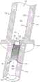
图1根据本公开的一些实施例描绘了具有可以采用本公开的原理的医用连接器的IV套件的透视图。1 depicts a perspective view of an IV set with a medical connector that may employ principles of the present disclosure, according to some embodiments of the present disclosure.
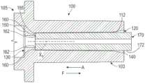
图2是根据本公开的一些实施例的图1的医用连接器的横截面视图。2 is a cross-sectional view of the medical connector of FIG. 1 according to some embodiments of the present disclosure.
图3是根据本公开的一些实施例的图2的连接器的管件部段的轴向花键和通道的局部横截面视图。3 is a partial cross-sectional view of the axial splines and channels of the tube section of the connector of FIG. 2 according to some embodiments of the present disclosure.
图4是根据本公开的一些实施例的图2的连接器的管件部段的轴向花键和通道的放大局部视图。4 is an enlarged partial view of the axial splines and channels of the tube section of the connector of FIG. 2 according to some embodiments of the present disclosure.
图5是根据本公开的一些实施例的图2的连接器的横截面视图,包括插入其中的管件。5 is a cross-sectional view of the connector of FIG. 2 , including a tube inserted therein, according to some embodiments of the present disclosure.
图6根据本公开的一些实施例示出了用于在图2的连接器的内圆周表面上形成管件轮廓和鲁尔件轮廓的芯销。6 illustrates a core pin used to form a tube profile and a luer profile on the inner circumferential surface of the connector of FIG. 2, according to some embodiments of the present disclosure.
图7是根据本公开的一些实施例的图2的连接器(以虚线示出)的剖视图,包括设置在其中的图6的芯销。7 is a cross-sectional view of the connector (shown in phantom) of FIG. 2 including the core pin of FIG. 6 disposed therein, according to some embodiments of the present disclosure.
图8是根据本公开的一些实施例的沿着图7的线8-8的横截面视图。Figure 8 is a cross-sectional view along line 8-8 of Figure 7, according to some embodiments of the present disclosure.
具体实施方式Detailed ways
本公开的各种实施例涉及提供一种用于IV装置的具有更大管件保持力的连接器,该连接器使用具有用于结合的最小表面积的微孔管件。Various embodiments of the present disclosure are directed to providing a connector for an IV set with greater tubing retention using microporous tubing with minimal surface area for engagement.
本公开的各种实施例还涉及提供具有改进的密封能力的连接器,以便防止流体在管件(例如,微孔管件)的外表面和连接器的内表面之间的意外泄漏。Various embodiments of the present disclosure also relate to providing connectors with improved sealing capabilities to prevent accidental leakage of fluid between the outer surface of a tubing (eg, microbore tubing) and the inner surface of the connector.
所公开的实施例涉及一种连接器,该连接器具有保持机构,用于在管件中没有流体(或流体减少)的情况下防止与其联接的微孔管件从连接器上脱离和/或分开。本文公开的实施例进一步涉及一种连接器,该连接器具有限制机构,以用于将管件保持在连接器中,并且在管件和连接器的内表面之间进行密封。如本文所公开的,保持机构可以包括沿着连接器的管件部分的内圆周轴向延伸的多个花键。当流体管线(管件)插入管件部分中时,轴向花键的边缘可以钻入管件中并且夹紧管件,用于连接器的管件部分内的更大的管件保持。例如,流体管线可以以过盈配合插入到管件部分中,由此流体管线的外径略大于管件部分的内径。因此,需要在管件上施加相对较强的拉力,以将管件从连接器分开或脱离。因此,可以使管件的意外分离最小化。The disclosed embodiments relate to a connector having a retention mechanism for preventing disengagement and/or separation of a microbore tubing coupled thereto from the connector in the absence of fluid (or reduced fluid) in the tubing. Embodiments disclosed herein further relate to a connector having a restraint mechanism for retaining a tubing within the connector and providing a seal between the tubing and an inner surface of the connector. As disclosed herein, the retention mechanism may include a plurality of splines extending axially along the inner circumference of the tubular portion of the connector. When a fluid line (tubing) is inserted into the tubing portion, the edges of the axial splines can drill into the tubing and grip the tubing for larger tubing retention within the tubing portion of the connector. For example, the fluid line may be inserted into the tubular portion with an interference fit whereby the outer diameter of the fluid line is slightly larger than the inner diameter of the tubular portion. Accordingly, a relatively strong pulling force needs to be exerted on the tubing to separate or disengage the tubing from the connector. Thus, accidental separation of the tubing can be minimized.
进一步有利的是,邻近的相邻花键在其间限定相应的凹部或通道,其类似地沿着连接器的管件部分的内圆周轴向延伸。因此,用于将流体管线或管件结合到管件部分的增加量的溶剂可以被收集到通道中,用于最大程度的结合。这将确保溶剂的均匀扩散,并且消除结合表面上可能出现的流体刮擦。这与传统的连接器和流体管线结合技术形成对比,在传统的连接器和流体管线结合技术中,溶剂流入连接器中,并且一旦管件插入连接器中,溶剂则会受到管件的刮擦,从而减小管件和连接器之间用于结合的溶剂的表面积。It is further advantageous that adjacent adjacent splines define therebetween respective recesses or channels which similarly extend axially along the inner circumference of the tubular part of the connector. Thus, increased amounts of solvent used to bond the fluid line or fitting to the fitting portion can be collected into the channel for maximum bonding. This will ensure even spreading of the solvent and eliminate possible fluid scraping on the bonding surface. This is in contrast to traditional connector and fluid line bonding techniques where solvent flows into the connector and is scraped by the fitting once the fitting is inserted into the connector, thereby Reduce the surface area of the solvent used for bonding between the fitting and the connector.
如本文所公开的,约束机构可以包括径向突出部、密封环,或者倒钩接头、倒钩边缘或可以保持管件的类似结构。因为管件和连接器之间存在过盈配合,所以限制机构确保了在低压条件期间(例如,在管件中缺乏流体期间)管件和连接器的内表面之间保持密封。因此,需要在管件上施加相对较强的拉力,以将管件从连接器上分开或脱离。因此,使管件的意外分离最小化。As disclosed herein, the restraint mechanism may include radial projections, sealing rings, or barbed fittings, barbed edges, or similar structures that may retain tubing. Because of the interference fit between the tubing and the connector, the restricting mechanism ensures that a seal is maintained between the inner surfaces of the tubing and connector during low pressure conditions (eg, during lack of fluid in the tubing). Accordingly, a relatively strong pulling force needs to be exerted on the tubing to separate or disengage the tubing from the connector. Thus, accidental separation of the tubing is minimized.
在一些实施例中,限制机构可以包括在连接器的内表面上的一个或更多个径向突出部或凸耳,当插入连接器时,该径向突出部或凸耳限制管件在连接器中的延伸。如下所述,与接收管件的端部相对的端部处,连接器可以包括母鲁尔接头。限制机构防止管件在组装期间延伸到母鲁尔接头中,从而确保医用连接器的正确操作。In some embodiments, the restraint mechanism may include one or more radial protrusions or lugs on the inner surface of the connector that, when inserted into the connector, restrain the tubing from the position of the connector. in the extension. As described below, at the end opposite the end that receives the tubing, the connector may include a female luer. The restraint mechanism prevents the tubing from extending into the female luer during assembly, thereby ensuring proper operation of the medical connector.
根据公开的实施例,医用连接器的另一优点是医用连接器的制造成本没有显著增加。可以以最小的成本来修改现有的制造装备,以制造示例医用连接器。例如,可以重新设计用于制造医用连接器的注塑模制装备的芯销,以形成轴向花键和通道以及约束机构。Another advantage of the medical connector according to the disclosed embodiments is that the manufacturing cost of the medical connector does not increase significantly. Existing manufacturing equipment can be modified at minimal cost to manufacture the example medical connectors. For example, core pins of injection molding equipment used to manufacture medical connectors can be redesigned to form axial splines and channels and restraint mechanisms.
如本文所用,术语“管件”、“流体管线”及其任何变型指的是用于将液体、溶剂或流体(包括气体)输送给接受医用护理的患者或从接收医用护理的患者处输送液体、溶剂或流体(包括气体)的医用管线或管子。例如,流体管线(管件)可以用于流体的静脉注射(IV)输送、流体排出、氧气输送、及其组合等。As used herein, the terms "tubing", "fluid line" and any variations thereof refer to a device used to transport liquids, solvents or fluids (including gases) to or from patients receiving medical care Medical lines or tubing for solvents or fluids, including gases. For example, fluid lines (tubing) may be used for intravenous (IV) delivery of fluids, fluid drainage, oxygen delivery, combinations thereof, and the like.
如本文所用,术语“医用连接器”、“连接器”、“接头”及其任何变型指的是用于在与其联接的两个或更多个流体管线之间提供流体流动路径的任何装置。例如,医用连接器可以是或可以包括结合袋或其他类型的连接器。As used herein, the terms "medical connector", "connector", "fitting" and any variations thereof refer to any device for providing a fluid flow path between two or more fluid lines coupled thereto. For example, a medical connector may be or include a bond bag or other type of connector.
图1根据本公开的一些实施例描绘了具有医用连接器100的IV套件10的透视图,该医用连接器可以采用本公开的原理。如图所示,IV套件可以包括流体源(比如流体袋2),该流体源可以包括或含有待给患者施用的盐溶液或其他流体。如图所示,第一管件6承载来自滴注室4的流量,通过连接器100,并且进入到第二流体管线或管件170中。IV泵(未示出)经由第二管件170从流体系统2接收流体,并且控制流体并且将流体从其分配给患者。如下面将进一步详细描述的,连接器100的管状部分具有被构造成接收第二管件170的内孔。出于本公开的目的,第二管件170将被描述为微孔管件或小孔管件,并且连接器100因此将被描述为被构造成接收和保持微孔管件。然而,本文描述的连接器的各种实施例可以应用于其他类型的管件,例如广孔管件或大孔管件。FIG. 1 depicts a perspective view of an IV set 10 having a
图2根据所公开的实施例示出了图1的医用连接器100的横截面视图。如图所示,医用连接器100(或简称为连接器)可以包括大致圆柱形的主体101,该主体具有“第一”或管件部分103和“第二”或鲁尔件部分105,该“第二”或鲁尔件部分与管件部分103轴向相对并且与其连接。在一些实施例中,主体101还可以包括沿着主体101的外表面设置的把手107。管件部分103可包括管件端口120,该管件端口的尺寸和形状可以设置为或以其他方式被构造成接收流体管线(下文称为“管件”),如下所述。类似地,鲁尔件部分105可包括鲁尔件端口125,该鲁尔件端口的尺寸和形状可以设置为或以其他方式被构造成接收公鲁尔连接器。如图所示,主体101限定了内部纵向通路或孔140,该内部纵向通路或孔从管件端口120延伸到鲁尔件端口125并且将管件端口120和鲁尔件端口125彼此流体连接。FIG. 2 illustrates a cross-sectional view of the
在所描绘的实施例中,内孔140由主体101的内圆周表面112限定,并且从管件端口120到鲁尔件端口125是连续的。在一些实施例中,管件部分103和鲁尔件部分105中的内圆周表面112具有两个不相似的轮廓。具体地说,管件部分103中的内圆周表面112具有管件轮廓135,鲁尔件部分105中的内圆周表面115具有鲁尔件轮廓133。连接器100的管件轮廓135和由此的管件部分103的尺寸和形状被设置成(或以其他方式被构造成)接收管件。具体而言,管件轮廓135可以定尺寸、定形状,以及以其他方式被构造成接收微孔管件170(在下面进一步详细描述)。例如,具有小于0.100英寸的内径的管件,并且特别是具有大约0.079英寸或更小的外径的管件,被认为是“小孔”或“微孔”,并且被结合到管件袋(比如管件轮廓135中限定的内孔140)中。具有大于0.100英寸的内径的管件通常被认为是“广孔(macrobore)”。本文相对于“小孔”管件或“微孔”管件形式的管件和用于“小孔”管件或“微孔”管件的袋结合,对本公开的示例性实施例进行了说明和描述。然而,本公开的各种实施例不限于上述构造,并且可以类似地应用于“大孔”管件或“广孔”管件和相关的连接器,以及“微孔”和“广孔”连接器之间的任何其他中间尺寸的管件和连接器。连接器100的鲁尔件轮廓133和由此的管件部分105的尺寸和形状可以被设置成(或以其他方式被构造成)接收公鲁尔接头。鲁尔件轮廓133和由此的鲁尔件部分105可以符合ISO-594。In the depicted embodiment,
在组装期间,为了限制插入、推进或以其他方式“滑动”到连接器100中的管件的延伸范围,内圆周表面112可以包括限制机构(以下称为“限制件130”)。限制件130可以被限定为从内圆周表面112径向向内突出,并且可以介于鲁尔件轮廓133和管件轮廓135之间。在一些实施例中,限制件130用作将管件插入鲁尔件轮廓133中限定的内孔140中的止动件。因此,限制件130可以具有直径D2(如图6所示),该直径D2小于管件轮廓135中限定的内孔140的最小直径D1。To limit the extent of tubing inserted, pushed or otherwise "slid" into
根据一些实施例,管件部分103的管件轮廓135可以包括保持机构,以用于提高连接器100保持插入其中的微孔管件170的能力,从而防止微孔管件170从连接器100分离(或以其他方式脱开)。例如,在由于管件中流体减少而在管件中产生低压条件期间,保持机构可以防止微孔管件170与连接器100分开(或以其他方式脱开)。在示例中,并且如图所示,保持机构可以是或可以包括沿着连接器100的管件部分103的内圆周表面112的长度直线延伸的多个花键115。当微孔管件170(如图5所示)被插入到连接器100的管件部分103中时,管件部分103中的内圆周表面112被构造成在联接构造中接合微孔管件170的外表面。例如,当微孔管件170被插入到管件部分103中时,轴向花键115的边缘137可以钻入管件的外表面中并且夹紧管件的外表面,用于连接器的管件部分内的更好的管件保持。因此,在联接构造中,微孔管件170可以以过盈配合插入到管件部分中,使得轴向花键115的边缘137钻入、夹紧并且接合微孔管件170的外表面,以将微孔管件170保持在连接器100的管件部分103中。上述构造提供了这样的优点,即一旦轴向花键115的边缘137钻入、夹紧并且接合微孔管件170的外表面,则微孔管件170和内圆周表面112之间的摩擦增加,使得微孔管件170可能不容易从连接器100脱开,而不脱离本公开的范围。例如,通过咬入或钻入微孔管件170的外表面,当在微孔管件170上施加拉力(图5所示,由箭头F指示的方向)以将其从连接器100移除时,轴向花键可以增加连接器100和微孔管件170之间的摩擦。因此,有利的是,从连接器100移除微孔管件170或以其他方式脱开微孔管件170所需的拉力增加,并且因此微孔管件170更好地固定和保持在连接器100中。此外,微孔管件170中的流体可以在径向向外的方向上施加压力,这可以进一步增加微孔管件170和内圆周表面112之间的摩擦。According to some embodiments, the
根据一些实施例,邻近的相邻花键115在其间限定相应的凹部或通道145。通道145类似地沿着连接器100的管件部分103的内圆周表面112轴向延伸。有利的是,用于将微孔管件170结合到限定在管件部分103中的内圆周表面115上的增加量的溶剂可以被收集到通道145中,用于最大程度的结合。特别地,在通道145中收集溶剂允许增加量的溶剂可用于将微孔管件170结合到管件部分103的内圆周表面115。向通道145提供收集在其中的溶剂将产生均匀的溶剂扩散,并且消除管件部分103的结合表面上可能出现的流体刮擦。因此,最大量的溶剂保持为可用于将微孔管件170结合到管件部分103的内圆周表面115,并且甚至可以实现更好的管件保持。这与传统的连接器和管件结合技术形成对比,在传统的连接器和管件结合技术中,溶剂流入连接器中,并且一旦流体管线/管件插入连接器中,则溶剂会受到管件的刮擦,从而减小了管件和连接器之间的溶剂的表面积。According to some embodiments, adjacent
图3是根据本公开的一些实施例的图2的连接器的管件部段的轴向花键和通道的局部横截面视图。图4是根据本公开的一些实施例的图2的连接器的管件部段的轴向花键和通道的放大局部视图。3 is a partial cross-sectional view of the axial splines and channels of the tube section of the connector of FIG. 2 according to some embodiments of the present disclosure. 4 is an enlarged partial view of the axial splines and channels of the tube section of the connector of FIG. 2 according to some embodiments of the present disclosure.
参考图3和图4,继续参考图2,每个轴向花键可以由第一倾斜表面117、第二倾斜表面119以及介于第一和第二倾斜表面117和119之间的边缘137限定。如图所示,轴向花键可以形成为花键齿轮的齿的形状。由于通道145限定在相邻的花键115之间,每个通道145由在顶点121处相交的相邻的第一和第二倾斜表面117和119限定。然而,轴向花键115和通道145的形状不限于上述构造。例如,轴向花键115和通道145可以不限制于任何特定的形状或尺寸,只要轴向花键115具有“咬入”、“钻入”、夹紧或以其他方式接合微孔管件170的外表面的形状,并且只要通道145形成足够深度的凹部以在其中含有溶剂。Referring to FIGS. 3 and 4 , with continued reference to FIG. 2 , each axial spline may be defined by a first
根据一些实施例,轴向花键115和通道145可以沿着管件部分103的内圆周表面112以规则的间隔设置。然而,在其他实施例中,轴向花键115和通道145可以沿着管件轮廓135的内圆周表面112以不规则的间隔设置。According to some embodiments, the
根据一些实施例,相邻花键的第一倾斜侧117和第二倾斜侧119之间的角度α范围从约30度到150度,更典型的是约60度到120度,80度到100度,或者在一些情况下大约为90度。尽管根据某些范围进行了叙述,但是应当理解,从下限的最低值到上限的最高值的所有范围都包括在内,包括该完整范围或任何具体叙述范围内的所有中间范围或特定角度。According to some embodiments, the angle α between the first
在一些实施例中,从每个花键的顶点121到边缘137测量的每个花键的高度范围可以从约0.0001英寸到0.002英寸,更典型的约0.0005英寸到0.00195英寸,0.001英寸到0.002英寸,或者在一些情况下大约为0.0015英寸。因此,由相邻花键115限定的通道145的每一个的深度范围可以从约0.0001英寸到0.002英寸,更典型的约0.0005英寸到0.00195英寸,0.001英寸到0.002英寸,或者在一些情况下大约为0.0015英寸。尽管根据某些范围进行了叙述,但是应当理解,从下限的最低值到上限的最高值的所有范围都包括在内,包括该完整范围或任何具体叙述范围内的所有中间范围或特定尺寸。In some embodiments, the height of each spline, measured from
在一些实施例中,通道的每一个的深度在朝向管件端口120的方向上逐渐变小。例如,每个通道145可以在邻近限制件130的第二端155的区域中具有最大深度。随着通道145接近管件端口120,每个通道145的深度可以逐渐减小,直到每个通道145终止。In some embodiments, the depth of each of the channels tapers in a direction toward the
向回参考图2,轴向花键115的每一个的长度跨越管件部分103的内圆周表面112的长度的一部分。在一些实施例中,轴向花键115的长度跨越在管件部分103的内圆周表面112的长度的约10%和90%之间,更典型地在约25%和75%之间,在约40%和60%之间,或者在一些情况下近似为管件部分103的内圆周表面112的长度的50%。由于通道145被限定在相邻的轴向花键115之间,所以每个通道145的长度类似地可以跨越在管件部分103的内圆周表面112的长度的约10%和90%之间,更典型地在约25%和75%之间,在约40%和60%之间,或者在一些情况下近似为管件部分103的内圆周表面112的长度的50%。尽管根据某些范围进行了叙述,但是应当理解,从下限的最低值到上限的最高值的所有范围都包括在内,包括该完整范围或任何具体叙述范围内的所有中间范围或特定百分比。为了防止意外的流体泄漏,以及防止溶剂意外地从管件部分103泄漏出来,确保通道不会一直延伸通过管件端口是有利的。Referring back to FIG. 2 , the length of each of the
图5是根据本公开的一些实施例的图2的连接器100的横截面视图,包括插入其中的微孔管件170。如先前所述,连接器100可以包括限制件130。如图5所示,限制件130可以包括沿着鲁尔件轮廓133限定的第一端150和沿着管件轮廓135限定的第二端155。在所描绘的实施例中,第二端155可以包括径向突出部160,该径向突出部从管件轮廓135的内圆周表面112径向向内突出(或以其他方式突出)并且与管件轮廓135的内圆周表面112成一定角度。径向突出部160可以被构造成钻入、夹紧或以其他方式接合微孔管件170的第一端,以在限制件130的第二表面155和微孔管件170之间形成密封,从而防止流体在微孔管件170的外表面172和限定在管件部分103中的内圆周表面112之间意外泄漏。在一些实施例中,径向突出部160围绕内孔140的中心轴线X1呈圆形设置。FIG. 5 is a cross-sectional view of the
径向突出部160可以形成密封环,该密封环防止流体在微孔管件170的外表面和限定在管件部分103中的内圆周表面112之间意外泄漏。在一些实施例中,径向突出部160可以形成有底切,以便充分“咬合”或以其他方式接合微孔管件170的第一端。
在一些实施例中,径向突出部160突出到内孔140中的最大距离小于或等于微孔管件170的厚度。这防止径向突出部160阻塞流过插入到连接器100中的管件的流体。只要限制件130防止插入连接器100中的管件的延伸,那么限制件130可以不限于任何特定的形状或尺寸。In some embodiments, the
因此,在一些实施例中,径向突出部160还可以充当保持机构,用于提高连接器100保持插入其中的微孔管件170的能力,从而防止微孔管件170与连接器100分离(或以其他方式脱开),例如,在由于管件中流体减少而在管件中形成低压条件期间。在示例中,如图所示,径向突出部160可以设置在管件部分和鲁尔件部分105之间的边界处或附近。如图所示,径向突出部160可以从内圆周表面112径向向内突出一定距离,进入限定在管件部分103中的内孔140中。在示例中,径向突出部160可以是从内圆周表面112延伸的长钉状结构。Therefore, in some embodiments, the
有利的是,径向突出部160因此可以是增加微孔管件170的外表面和内圆周表面112之间的摩擦的结构,使得微孔管件170可以不容易从连接器100脱开,而不脱离本公开的范围。在一些实施例中,径向突出部160可以被构造为具有轻微底切的斜坡,该斜坡被构造成当微孔管件170被插入或推进到连接器100中时略微按压该微孔管件。当微孔管件170被拉动以从连接器抽出时,斜坡的顶部,以及在一些实施例中的底切部分,将微孔管件170固定在连接器100内,如图5所示。在一些实施例中,当试图从连接器100内抽出微孔管件170时,斜坡的顶部或底切部分将钻入或夹紧微孔管件,如下面进一步解释的。Advantageously, the
参考图5,继续参考图2,微孔管件170可以大致沿着箭头A的方向插入连接器100中,并且径向突出部160可以具有渐缩的远侧端部162,该渐缩的远侧端部大致沿着微孔管件170插入连接器100中的方向取向。微孔管件170可以相对容易地插入连接器100中。然而,当在微孔管件170上施加拉力(箭头F指示的方向)以将其从连接器100移除时,径向突出部160可以增加连接器100和微孔管件170之间的摩擦。因此,有利的是,从连接器100移除或以其他方式脱开微孔管件170所需的拉力增加,并且因此微孔管件170更好地固定在连接器100中。此外,微孔管件170中的流体可以在径向向外的方向上施加压力,这可以进一步增加微孔管件170和径向突出部160之间的摩擦。5, with continued reference to FIG. 2,
应当注意,在附图中,径向突出部在内圆周表面112上的位置仅是示例,并且该位置可以改变,而不脱离本公开的范围。此外,尽管附图指示了一个径向突出部,但是该径向突出部可以被替换,例如用凸耳和/或倒钩特征替换,其数量可以不受限制,并且可以增加或减少,而不脱离本公开的范围。例如,多个凸耳可以沿着管件部分103中的内圆周表面112以规则的间隔设置。然而,在其他实施例中,凸耳可以沿着内圆周表面112以不规则的间隔设置。类似地,多个倒钩特征可以沿着管件部分103中的内圆周表面112以规则的间隔设置。然而,在其他实施例中,倒钩特征可以以不规则的间隔设置。倒钩特征的圆周延伸范围可以在内圆周表面112的四分之一象限周围。然而,在其他示例中,倒钩特征的圆周延伸范围可以根据应用或设计的需要而增加或减少,并且不脱离本公开的范围。It should be noted that in the drawings, the position of the radial protrusion on the inner
图6根据本公开的一些实施例示出了用于在图2的连接器100的内圆周表面112上分别形成管件轮廓135和鲁尔件轮廓133的芯销201和203。根据一些实施例,连接器100可以使用注塑模制工艺制造。然而,在不脱离本公开的范围的情况下,也可以使用其他制造工艺来制造连接器100。在示例中,芯销201可以形成内圆周表面112的鲁尔件轮廓133,并且芯销203可以形成内圆周表面112的管件轮廓135。为了简洁起见,省略了用于在主体101的外表面上形成特征(例如,把手107)的工艺步骤和模具。FIG. 6 illustrates core pins 201 and 203 for forming
如图所示,芯销201具有大致细长的主体202,该主体具有鲁尔件成形部分206和限制件成形部分208。鲁尔件成形部分206具有大致圆柱形的外表面212,其具有的直径大于限制件成形部分208的直径。鲁尔件成形部分206的外表面212成形为形成鲁尔件轮廓133(如图2所示)。限制件形成轮廓210可以形成在外表面212上,靠近鲁尔件成形部分206的远侧端部218。As shown, the
根据一些实施例,芯销203也具有大致细长的主体222,该主体具有带有圆柱形外表面226的基部部分225和带有圆柱形外表面222的管件成形部分220。在一些实施例中,基部部分225的直径D4大于管件成形部份220的直径D3。圆柱形外表面222的形状和尺寸被设置为形成管件部分103的管件轮廓135(图2)。在所描绘的实施例中,管件成形部分220的圆柱形外表面222可以形成有多个轴向延伸的齿224,该多个轴向延伸的齿224沿着外表面222的径向外部形成。相邻的齿224可以在其间限定凹部215。如下所述,在制造期间,齿224限定了通道145的形状,并且凹部215限定了连接器的轴向花键115的形状。According to some embodiments, the
在所描绘的实施例中,每个轴向延伸的齿224的长度可以跨越管件部分103的内圆周表面112的长度的一部分。在一些实施例中,轴向延伸的齿224的长度跨越在管件部分103的内圆周表面112的长度的约10%和90%之间,更典型地在约25%和75%之间,在约40%和60%之间,或者在一些情况下近似为管件部分103的内圆周表面112的长度的50%。由于凹部215被限定在相邻的轴向延伸的齿224之间,所以凹部的每一个的长度类似地可以跨越在管件部分103的内圆周表面112的长度的约10%和90%之间,更典型地在约25%和75%之间,在约40%和60%之间,或者在一些情况下近似为管件部分103的内圆周表面112的长度的50%。尽管根据某些范围进行了叙述,但是应当理解,从下限的最低值到上限的最高值的所有范围都包括在内,包括该完整范围或任何具体叙述范围内的所有中间范围或特定百分比。In the depicted embodiment, the length of each
图7是根据本公开的一些实施例的图2的连接器(以虚线示出)的剖视图,包括设置在其中的图6的芯销201和203。图8是根据本公开的一些实施例的沿着图7的线8-8截取的连接器100和芯销203的横截面视图。根据一些实施例,连接器100可以使用注塑模制工艺制造。连接器100可以由塑料或可以被模制成所需形状的类似材料制成。外部模具(未示出)可以用于形成连接器100的外部特征。这些外部特征可以包括把手107和圆柱形主体101的外表面。内孔140、管件轮廓135、鲁尔件轮廓133、限制件130和径向突出部160可以使用芯销201和203形成。7 is a cross-sectional view of the connector (shown in phantom) of FIG. 2 including core pins 201 and 203 of FIG. 6 disposed therein, according to some embodiments of the present disclosure. 8 is a cross-sectional view of
在制造期间,可以将形成连接器100的材料放置在模制工具中,该模制工具包括彼此轴向对齐的芯销201和203。芯销201和203可以从轴向相对端一起被带至材料中。该材料可以是半固态、可延展状态,以便将其模制成所需的形状。芯销201和203可以朝向彼此靠近,直到芯销201和203彼此联接,如图7所示。During manufacture, the material forming the
向回参考图6,芯销203的管件成形部分220的远侧端部219可以包括径向突出部形成轮廓228,该径向突出部成形轮廓包括形成为环,该环具有径向向内成角度的内表面229和穿过其中限定的空腔230。当芯销201和203彼此联接时,芯销201的远侧端部218被部分地接收到由径向突出部形成轮廓228限定的空腔230中。具体而言,如图所示,芯销201的远侧端部218与径向突出部形成轮廓228的内表面229同心设置,并且径向位于其内部。限制件成形部分208和径向突出部形成轮廓228共同形成限制件130和径向突出部。具体而言,当芯销201和203彼此联接时,在限制件成形部分208和径向突出部形成轮廓228之间形成空隙。该空隙用半固态、可延展的连接器材料填充,并且模制成空隙的形状(即径向突出部160的形状)。Referring back to FIG. 6 , the
此外,在制造期间,当芯销201和203彼此联接,并且半固态、可延展的连接器材料被放置在包括彼此轴向对齐的芯销201和203的模制工具中时,轴向延伸的齿224可以刺入半固态、可延展的连接器材料中并且在其中形成印记。半固态、可延展的连接器材料也可以填充凹部215,并且被模制成由凹部215限定的形状。一旦半固态、可延展的连接器材料固化,则芯销201和203被移除。当芯销203被移除时,沿着管件部分103的内圆周表面112形成轴向延伸的凹部,其中轴向延伸齿224刺入连接器材料中。轴向延伸的通道对应于管件部分103的管件轮廓135中的轴向延伸的通道145。类似地,当芯销203被移除时,轴向延伸的花键沿着管件部分103的内圆周表面112突出,其中半固态、可延展的连接器材料填充凹部215。填充的凹部215对应于在管件部分103的管件轮廓135上形成的轴向花键115。Furthermore, during manufacture, when the core pins 201 and 203 are coupled to each other and the semi-solid, malleable connector material is placed in a molding tool comprising the core pins 201 and 203 axially aligned with each other, the axially extending The
如先前所述,在一些实施例中,每个通道145的深度在朝向管件端口120的方向上逐渐减小。每个通道145的深度的逐渐减小是由于管件轮廓135的构造引起的。例如,如图所示,管件轮廓135的邻近限制件130的端部处的内孔140的直径D1小于管件轮廓135的邻近管件端口120的端部处的内孔140的直径D2。因此,管件轮廓135在从邻近管件端口120的端部到邻近限制件130的端部的方向上渐缩。当具有轴向延伸的齿224的芯销203与用于形成连接器100的材料一起定位在模具中时,齿224在管件轮廓的邻近限制件130的区域中更深地钻入连接器材料中(由于较小的直径D1),并且在管件端口120的方向上逐渐更少地钻入连接器材料中(由于在管件端口的方向上直径增加到D2)。由于齿224在管件轮廓135的邻近限制件130的区域中更深地钻入连接器材料中,所以产生的通道145具有更大的深度,并且产生的轴向花键在该区域中比在接近管件端口120的区域中具有更大的高度。As previously noted, in some embodiments, the depth of each
上述构造的优点在于,轴向花键115能够在管件轮廓的邻近限制件130的区域中更大程度地咬入或夹紧微孔管件170,从而需要在微孔管件170上施加相对更强的拉力,以将微孔管件170与连接器100分离或脱开。因此,可以使微孔管件170与连接器100的意外分离最小化。An advantage of the configuration described above is that the
根据一些实施例,轴向花键115和通道145可以沿着管件部分103的内圆周表面112以规则的间隔设置。然而,在其他实施例中,轴向花键115和通道145可以沿着管件轮廓135的内圆周表面112以不规则的间隔设置。According to some embodiments, the
根据一些实施例,相邻花键的第一倾斜侧117和第二倾斜侧119之间的角度α范围从约30度到150度,更典型的是约60度到120度,以及80度到100度,或者在一些情况下近似90度。尽管根据某些范围进行了叙述,但是应当理解,从下限的最低值到上限的最高值的所有范围都包括在内,包括该完整范围或任何具体叙述范围内的所有中间范围或特定角度。According to some embodiments, the angle α between the first
在一些实施例中,类似于轴向花键115,每个凹部215的深度范围可以从约0.0001英寸到0.002英寸,更典型的是约0.0005英寸到0.00195英寸,0.001英寸到0.002英寸,或者在一些情况下近似0.0015英寸。因此,类似于轴向通道145,每个轴向延伸的齿224的高度H范围可以从约0.0001英寸到0.002英寸,更典型的是约0.0005英寸到0.00195英寸,0.001英寸到0.002英寸,或者在一些情况下近似0.0015英寸。尽管根据某些范围进行了叙述,但是应当理解,从下限的最低值到上限的最高值的所有范围都包括在内,包括该完整范围或任何具体叙述范围内的所有中间范围或特定尺寸。In some embodiments, similar to the
提供先前的描述是为了使本领域中的任何技术人员能够实践本文描述的各个方面。虽然前述已经描述了被认为是最佳模式和/或其他示例,但是应当理解,对这些方面的各种修改对于本领域技术人员来说将是显而易见的,并且本文定义的一般原理可以应用于其他方面。因此,权利要求并不旨在局限于本文所示的方面,而是要符合与语言权利要求一致的全部范围,其中,除非特别说明,否则对单数形式的元件的引用并不旨在意味着“一个且仅一个”,而是“一个或更多个”。除非另有特别说明,否则术语“一组”和“一些”指代一个或更多个。阳性代词(例如,他的)包括阴性和中性代词(例如,她的和它的),反之亦然。标题和副标题,如果有的话,仅是为了方便而使用,并且不限制本发明。The previous description was provided to enable any person skilled in the art to practice the various aspects described herein. While the foregoing has described what is considered the best mode and/or other examples, it should be understood that various modifications to these aspects will be readily apparent to those skilled in the art, and that the general principles defined herein may be applied to other examples. aspect. Accordingly, the claims are not intended to be limited to the aspects shown herein, but are to be accorded the full scope consistent with language claims wherein, unless specifically stated otherwise, reference to an element in the singular is not intended to mean " One and only one", but "one or more". Unless specifically stated otherwise, the terms "a set" and "some" refer to one or more. Masculine pronouns (eg, his) include feminine and neuter pronouns (eg, her and its), and vice versa. Headings and subheadings, if any, are used for convenience only and do not limit the invention.
应当理解,所公开的过程中步骤的特定顺序或层次是示例性方法的说明。基于设计偏好,应当理解,过程中的步骤的特定顺序或层次可以被重新安排。一些步骤可以同时执行。所附方法权利要求以样本顺序呈现各种步骤的元素,并且不意味着局限于所呈现的特定顺序或层次。It is understood that the specific order or hierarchy of steps in the processes disclosed is an illustration of exemplary approaches. Based upon design preferences, it is understood that the specific order or hierarchy of steps in the processes may be rearranged. Some steps can be performed simultaneously. The accompanying method claims present elements of the various steps in a sample order, and are not meant to be limited to the specific order or hierarchy presented.
如该公开中使用的比如“顶部”、“底部”、“前部”、“后部”等的术语,应理解为指代任意参考系,而不是指代普通的重力参考系。因此,顶部表面、底部表面、前部表面和后部表面可以在重力参考系中向上、向下、对角或水平延伸。Terms such as "top," "bottom," "front," "rear," etc., as used in this disclosure, should be understood to refer to an arbitrary frame of reference, rather than a general gravitational frame of reference. Thus, the top surface, bottom surface, front surface and rear surface may extend upwards, downwards, diagonally or horizontally in a gravitational frame of reference.
比如“方面”等的短语并不意指这种方面对于主题技术是必要的,或者这种方面可应用于主题技术的所有构造。与一个方面相关的公开可以应用于所有构造,或者一个或更多个构造。比如“方面”等的短语可以指代一个或更多个方面,反之亦然。比如“实施例”等的短语并不意指这种实施例对于主题技术是必要的,或者这种实施例可应用于主题技术的所有构造。与一个实施例相关的公开可以应用于所有实施例,或者一个或更多个实施例。比如“实施例”等的短语可以指代一个或更多个实施例,反之亦然。Phrases such as "aspects" etc. do not imply that such aspects are essential to the subject technology or that such aspects are applicable to all configurations of the subject technology. A disclosure related to an aspect may apply to all configurations, or one or more configurations. Phrases such as "aspects" and the like may refer to one or more aspects and vice versa. Phrases such as "an embodiment" and the like do not mean that such embodiments are essential to the subject technology, or that such embodiments are applicable to all configurations of the subject technology. A disclosure related to one embodiment may apply to all embodiments, or one or more embodiments. A phrase such as "an embodiment" may refer to one or more embodiments and vice versa.
在本文使用词语“示例性的”意味着“用作示例或说明”。本文描述为“示例性”的任何方面或设计不一定被解释为比其他方面或设计更优选或更有利。The word "exemplary" is used herein to mean "serving as an example or illustration." Any aspect or design described herein as "exemplary" is not necessarily to be construed as preferred or advantageous over other aspects or designs.
本领域中的普通技术人员已知的或以后将会知道的贯穿该公开描述的各个方面的元件的所有结构和功能等同物通过引用明确地并入本文中,并且旨在被权利要求所涵盖。此外,无论这种公开是否在权利要求中明确叙述,本文公开的任何内容都不旨在专用于公众。任何权利要求要素都不能根据《美国法典》第35篇第112节第六段的规定来解释,除非该要素是使用短语“用于......的手段”来明确叙述的,或者在方法权利要求的情况下,该要素是使用短语“用于......的步骤”来叙述的。此外,就说明书或权利要求中使用的术语“包括”、“具有”或相似术语而言,这种术语旨在以类似于术语“包含”的方式包含在内,如“包含”在权利要求中用作过渡词时被解释的那样。All structural and functional equivalents to the elements of the various aspects described throughout this disclosure that are known or later come to be known to those of ordinary skill in the art are expressly incorporated herein by reference and are intended to be encompassed by the claims. Furthermore, nothing disclosed herein is intended to be dedicated to the public regardless of whether such disclosure is explicitly recited in the claims. No claim element is to be construed under the sixth paragraph of 35 U.S.C. § 112 unless the element is expressly recited using the phrase "means for," or in In the case of a method claim, the element is recited using the phrase "step for". Furthermore, to the extent that the terms "comprises", "has" or similar terms are used in the specification or claims, such terms are intended to be included in a manner similar to the term "comprising", such as "comprising" in the claims as interpreted when used as a transition word.
Claims (20)
Translated fromChineseApplications Claiming Priority (4)
| Application Number | Priority Date | Filing Date | Title |
|---|---|---|---|
| US16/378,351US11185675B2 (en) | 2019-04-08 | 2019-04-08 | Luer having microbore tubing retention pocket bond with axial spline |
| US16/378,351 | 2019-04-08 | ||
| PCT/US2020/025279WO2020210053A1 (en) | 2019-04-08 | 2020-03-27 | Luer having microbore tubing retention pocket bond with axial spline |
| CN202080042032.1ACN113939331B (en) | 2019-04-08 | 2020-03-27 | Luer with microbore tubing retention bag coupled with axial spline |
Related Parent Applications (1)
| Application Number | Title | Priority Date | Filing Date |
|---|---|---|---|
| CN202080042032.1ADivisionCN113939331B (en) | 2019-04-08 | 2020-03-27 | Luer with microbore tubing retention bag coupled with axial spline |
Publications (1)
| Publication Number | Publication Date |
|---|---|
| CN115887905Atrue CN115887905A (en) | 2023-04-04 |
Family
ID=70416537
Family Applications (2)
| Application Number | Title | Priority Date | Filing Date |
|---|---|---|---|
| CN202080042032.1AActiveCN113939331B (en) | 2019-04-08 | 2020-03-27 | Luer with microbore tubing retention bag coupled with axial spline |
| CN202310045849.XAPendingCN115887905A (en) | 2019-04-08 | 2020-03-27 | Connector and method of manufacturing connector |
Family Applications Before (1)
| Application Number | Title | Priority Date | Filing Date |
|---|---|---|---|
| CN202080042032.1AActiveCN113939331B (en) | 2019-04-08 | 2020-03-27 | Luer with microbore tubing retention bag coupled with axial spline |
Country Status (7)
| Country | Link |
|---|---|
| US (2) | US11185675B2 (en) |
| EP (2) | EP3952975B1 (en) |
| JP (2) | JP7502327B2 (en) |
| CN (2) | CN113939331B (en) |
| AU (1) | AU2020270825B2 (en) |
| CA (1) | CA3136257A1 (en) |
| WO (1) | WO2020210053A1 (en) |
Families Citing this family (3)
| Publication number | Priority date | Publication date | Assignee | Title |
|---|---|---|---|---|
| US11185675B2 (en)* | 2019-04-08 | 2021-11-30 | Carefusion 303, Inc. | Luer having microbore tubing retention pocket bond with axial spline |
| DE102019205608B4 (en)* | 2019-04-17 | 2020-11-05 | Zf Friedrichshafen Ag | Parking lock wheel |
| US11614189B2 (en)* | 2020-11-10 | 2023-03-28 | Carefusion 303, Inc. | Spigot tube coupler with bonding agent groove |
Citations (4)
| Publication number | Priority date | Publication date | Assignee | Title |
|---|---|---|---|---|
| JP2012213867A (en)* | 2011-03-31 | 2012-11-08 | Jms Co Ltd | Medical connecting member and method of manufacturing the same |
| US20150335873A1 (en)* | 2014-05-20 | 2015-11-26 | Kimberly-Clark Worldwide, Inc. | Catheter Connector Insert |
| CN106456960A (en)* | 2014-02-11 | 2017-02-22 | 亨氏迈泽有限责任公司 | Device for connecting medical disposable articles in a sterile manner |
| WO2018193965A1 (en)* | 2017-04-17 | 2018-10-25 | 株式会社ジェイ・エム・エス | Connector assembly |
Family Cites Families (13)
| Publication number | Priority date | Publication date | Assignee | Title |
|---|---|---|---|---|
| US4452473A (en)* | 1982-07-26 | 1984-06-05 | Baxter Travenol Laboratories, Inc. | Luer connection system |
| US5176415A (en) | 1990-08-16 | 1993-01-05 | Choksi Pradip V | Taper fitting with protective skirt |
| CA2071353C (en)* | 1991-12-10 | 1998-10-06 | Amy M. Wendell | Microbore catheter with side port(s) |
| US5620427A (en) | 1995-04-27 | 1997-04-15 | David R. Kipp | Luer lock system |
| GB2365344A (en)* | 2000-08-04 | 2002-02-20 | Alan David Mogg | Catheter adaptor |
| US7740288B2 (en)* | 2005-05-09 | 2010-06-22 | Northgate Technologies Inc. | High-flow luer lock connector for a luer lock connection |
| CA2659089A1 (en)* | 2006-07-18 | 2008-01-24 | Mallinckrodt Inc. | Breakage resistant luer fitting |
| US20110121558A1 (en)* | 2007-08-20 | 2011-05-26 | Atrion Medical Products, Inc. | Bonding socket for high pressure medical hose |
| US9339640B2 (en)* | 2011-02-11 | 2016-05-17 | Carefusion 303, Inc. | Connector for multiple sizes of tubing |
| US9163759B2 (en)* | 2012-10-04 | 2015-10-20 | Delta Faucet Company | Fitting connection including compression nut with retainer |
| GB201608603D0 (en)* | 2016-05-16 | 2016-06-29 | Medical Device Creations Ltd | Improved fluid line connector device |
| US20180086905A1 (en)* | 2016-09-26 | 2018-03-29 | Becton, Dickinson And Company | Enhancing Bond Strength Of Medical Devices |
| US11185675B2 (en)* | 2019-04-08 | 2021-11-30 | Carefusion 303, Inc. | Luer having microbore tubing retention pocket bond with axial spline |
- 2019
- 2019-04-08USUS16/378,351patent/US11185675B2/enactiveActive
- 2020
- 2020-03-27CACA3136257Apatent/CA3136257A1/enactivePending
- 2020-03-27CNCN202080042032.1Apatent/CN113939331B/enactiveActive
- 2020-03-27CNCN202310045849.XApatent/CN115887905A/enactivePending
- 2020-03-27WOPCT/US2020/025279patent/WO2020210053A1/ennot_activeCeased
- 2020-03-27EPEP20721022.0Apatent/EP3952975B1/enactiveActive
- 2020-03-27JPJP2021559394Apatent/JP7502327B2/enactiveActive
- 2020-03-27EPEP25189235.2Apatent/EP4606415A2/enactivePending
- 2020-03-27AUAU2020270825Apatent/AU2020270825B2/enactiveActive
- 2021
- 2021-10-28USUS17/513,578patent/US11957863B2/enactiveActive
- 2024
- 2024-06-06JPJP2024092210Apatent/JP7693059B2/enactiveActive
Patent Citations (4)
| Publication number | Priority date | Publication date | Assignee | Title |
|---|---|---|---|---|
| JP2012213867A (en)* | 2011-03-31 | 2012-11-08 | Jms Co Ltd | Medical connecting member and method of manufacturing the same |
| CN106456960A (en)* | 2014-02-11 | 2017-02-22 | 亨氏迈泽有限责任公司 | Device for connecting medical disposable articles in a sterile manner |
| US20150335873A1 (en)* | 2014-05-20 | 2015-11-26 | Kimberly-Clark Worldwide, Inc. | Catheter Connector Insert |
| WO2018193965A1 (en)* | 2017-04-17 | 2018-10-25 | 株式会社ジェイ・エム・エス | Connector assembly |
Also Published As
| Publication number | Publication date |
|---|---|
| JP7502327B2 (en) | 2024-06-18 |
| EP3952975B1 (en) | 2025-08-06 |
| EP3952975A1 (en) | 2022-02-16 |
| US11957863B2 (en) | 2024-04-16 |
| AU2020270825B2 (en) | 2025-01-02 |
| CN113939331B (en) | 2023-01-17 |
| US20220054816A1 (en) | 2022-02-24 |
| US20200316358A1 (en) | 2020-10-08 |
| EP4606415A2 (en) | 2025-08-27 |
| JP2024107171A (en) | 2024-08-08 |
| AU2020270825A1 (en) | 2021-11-11 |
| WO2020210053A1 (en) | 2020-10-15 |
| CA3136257A1 (en) | 2020-10-15 |
| JP7693059B2 (en) | 2025-06-16 |
| JP2022527369A (en) | 2022-06-01 |
| EP3952975C0 (en) | 2025-08-06 |
| US11185675B2 (en) | 2021-11-30 |
| CN113939331A (en) | 2022-01-14 |
Similar Documents
| Publication | Publication Date | Title |
|---|---|---|
| US20250120884A1 (en) | Dosing control coupling for enteral fluid transfer | |
| JP7693059B2 (en) | Luer having microbore tube retaining pocket joint with axial spline | |
| JP7214797B2 (en) | syringe filling adapter | |
| CN101528299B (en) | Fluid Connector System | |
| EP2331191B1 (en) | Closed male luer device for minimizing leakage during connection and disconnection | |
| WO2008144513A1 (en) | Low-volume fittings | |
| CN103517728A (en) | drug delivery connector | |
| CN115103700A (en) | Syringe with snap-in enteral connection feature | |
| CN112399866B (en) | Luer connector with tubing retention junction | |
| US20220096816A1 (en) | Needleless connector having check valve with valve pivot support | |
| CN108883027B (en) | Enteral feeding device connector | |
| US20210031021A1 (en) | Medical tube | |
| JP7618569B2 (en) | IV spikes for use with non-ISO compliant IV containers | |
| JP2025533126A (en) | Rotational Component | |
| AU2022268862A1 (en) | Needleless connector having check valve with asymmetric valve design and primary seal support | |
| CN116889401A (en) | Flow restriction device, method of manufacturing the same, and peripheral intravenous catheter assembly |
Legal Events
| Date | Code | Title | Description |
|---|---|---|---|
| PB01 | Publication | ||
| PB01 | Publication | ||
| SE01 | Entry into force of request for substantive examination | ||
| SE01 | Entry into force of request for substantive examination |