CN115885433A - Preformed wire routing in manifolds for implantable medical devices - Google Patents
Preformed wire routing in manifolds for implantable medical devicesDownload PDFInfo
- Publication number
- CN115885433A CN115885433ACN202180052748.4ACN202180052748ACN115885433ACN 115885433 ACN115885433 ACN 115885433ACN 202180052748 ACN202180052748 ACN 202180052748ACN 115885433 ACN115885433 ACN 115885433A
- Authority
- CN
- China
- Prior art keywords
- wire
- preformed
- turns
- feedthrough pin
- feedthrough
- Prior art date
- Legal status (The legal status is an assumption and is not a legal conclusion. Google has not performed a legal analysis and makes no representation as to the accuracy of the status listed.)
- Pending
Links
Images


Classifications
- A—HUMAN NECESSITIES
- A61—MEDICAL OR VETERINARY SCIENCE; HYGIENE
- A61N—ELECTROTHERAPY; MAGNETOTHERAPY; RADIATION THERAPY; ULTRASOUND THERAPY
- A61N1/00—Electrotherapy; Circuits therefor
- A61N1/18—Applying electric currents by contact electrodes
- A61N1/32—Applying electric currents by contact electrodes alternating or intermittent currents
- A61N1/36—Applying electric currents by contact electrodes alternating or intermittent currents for stimulation
- A61N1/372—Arrangements in connection with the implantation of stimulators
- A61N1/375—Constructional arrangements, e.g. casings
- A61N1/3752—Details of casing-lead connections
- A61N1/3754—Feedthroughs
- A—HUMAN NECESSITIES
- A61—MEDICAL OR VETERINARY SCIENCE; HYGIENE
- A61N—ELECTROTHERAPY; MAGNETOTHERAPY; RADIATION THERAPY; ULTRASOUND THERAPY
- A61N1/00—Electrotherapy; Circuits therefor
- A61N1/18—Applying electric currents by contact electrodes
- A61N1/32—Applying electric currents by contact electrodes alternating or intermittent currents
- A61N1/36—Applying electric currents by contact electrodes alternating or intermittent currents for stimulation
- A61N1/372—Arrangements in connection with the implantation of stimulators
- A61N1/375—Constructional arrangements, e.g. casings
- A61N1/3752—Details of casing-lead connections
- A—HUMAN NECESSITIES
- A61—MEDICAL OR VETERINARY SCIENCE; HYGIENE
- A61N—ELECTROTHERAPY; MAGNETOTHERAPY; RADIATION THERAPY; ULTRASOUND THERAPY
- A61N1/00—Electrotherapy; Circuits therefor
- A61N1/18—Applying electric currents by contact electrodes
- A61N1/32—Applying electric currents by contact electrodes alternating or intermittent currents
- A61N1/36—Applying electric currents by contact electrodes alternating or intermittent currents for stimulation
- A61N1/372—Arrangements in connection with the implantation of stimulators
- A61N1/375—Constructional arrangements, e.g. casings
- A61N1/37512—Pacemakers
- H—ELECTRICITY
- H01—ELECTRIC ELEMENTS
- H01R—ELECTRICALLY-CONDUCTIVE CONNECTIONS; STRUCTURAL ASSOCIATIONS OF A PLURALITY OF MUTUALLY-INSULATED ELECTRICAL CONNECTING ELEMENTS; COUPLING DEVICES; CURRENT COLLECTORS
- H01R2201/00—Connectors or connections adapted for particular applications
- H01R2201/12—Connectors or connections adapted for particular applications for medicine and surgery
- H—ELECTRICITY
- H01—ELECTRIC ELEMENTS
- H01R—ELECTRICALLY-CONDUCTIVE CONNECTIONS; STRUCTURAL ASSOCIATIONS OF A PLURALITY OF MUTUALLY-INSULATED ELECTRICAL CONNECTING ELEMENTS; COUPLING DEVICES; CURRENT COLLECTORS
- H01R24/00—Two-part coupling devices, or either of their cooperating parts, characterised by their overall structure
- H01R24/58—Contacts spaced along longitudinal axis of engagement
- H—ELECTRICITY
- H01—ELECTRIC ELEMENTS
- H01R—ELECTRICALLY-CONDUCTIVE CONNECTIONS; STRUCTURAL ASSOCIATIONS OF A PLURALITY OF MUTUALLY-INSULATED ELECTRICAL CONNECTING ELEMENTS; COUPLING DEVICES; CURRENT COLLECTORS
- H01R4/00—Electrically-conductive connections between two or more conductive members in direct contact, i.e. touching one another; Means for effecting or maintaining such contact; Electrically-conductive connections having two or more spaced connecting locations for conductors and using contact members penetrating insulation
- H01R4/10—Electrically-conductive connections between two or more conductive members in direct contact, i.e. touching one another; Means for effecting or maintaining such contact; Electrically-conductive connections having two or more spaced connecting locations for conductors and using contact members penetrating insulation effected solely by twisting, wrapping, bending, crimping, or other permanent deformation
- H01R4/14—Electrically-conductive connections between two or more conductive members in direct contact, i.e. touching one another; Means for effecting or maintaining such contact; Electrically-conductive connections having two or more spaced connecting locations for conductors and using contact members penetrating insulation effected solely by twisting, wrapping, bending, crimping, or other permanent deformation by wrapping
Landscapes
- Health & Medical Sciences (AREA)
- Engineering & Computer Science (AREA)
- Biomedical Technology (AREA)
- Nuclear Medicine, Radiotherapy & Molecular Imaging (AREA)
- Radiology & Medical Imaging (AREA)
- Life Sciences & Earth Sciences (AREA)
- Animal Behavior & Ethology (AREA)
- General Health & Medical Sciences (AREA)
- Public Health (AREA)
- Veterinary Medicine (AREA)
- Electrotherapy Devices (AREA)
Abstract
Translated fromChinese
Description
Translated fromChinese优先权要求priority claim
本申请根据35U.S.C.§119(e)要求于2020年8月31日提交的美国临时专利申请序列号63/072,371的优先权权益,该申请通过引用整体并入本文。This application claims the benefit of priority under 35 U.S.C. §119(e) to U.S. Provisional Patent Application Serial No. 63/072,371, filed August 31, 2020, which is incorporated herein by reference in its entirety.
技术领域technical field
本文件总体上涉及医疗设备中组件的电连接,并且更具体地,但不限于,涉及用于在可植入式医疗设备的外壳和耦合到外壳的集管中的电触点之间耦合预成型导线的系统和方法。This document relates generally to the electrical connection of components in medical devices, and more specifically, but not limited to, to pre-coupling electrical contacts for coupling between a housing of an implantable medical device and electrical contacts in a header coupled to the housing. Systems and methods for forming wires.
背景技术Background technique
医疗设备可以被植入或可植入在患者体内,诸如以监测患者,包括检测或感测来自患者的生理信息,诸如心音、呼吸(例如,呼吸率(RR)、潮气量(TV)等)、阻抗(例如,胸廓阻抗、心脏阻抗、皮肤阻抗等)、压力(例如,血压)、心脏活动(例如,心率、心电信息等)、化学物(例如,电解质)、身体活动、姿势、体积描记法中的一个或多个或患者的一个或多个其他生理信息,并且在某些示例中,在临床和流动环境中向患者提供治疗。可植入式医疗设备(IMD)可以包括心律管理(CRM)设备,诸如起搏器、心脏再同步设备、心脏复律器、除颤器、药物输送设备,或植入或可植入式患者体内或皮下的一个或多个其他IMD。A medical device may be implanted or implantable in a patient, such as to monitor the patient, including detecting or sensing physiological information from the patient, such as heart sounds, respiration (e.g., respiration rate (RR), tidal volume (TV), etc.) , impedance (eg, thoracic impedance, cardiac impedance, skin impedance, etc.), pressure (eg, blood pressure), cardiac activity (eg, heart rate, ECG information, etc.), chemicals (eg, electrolytes), physical activity, posture, volume One or more of the tracings or one or more other physiological information of the patient, and in some examples, providing therapy to the patient in clinical and ambulatory settings. Implantable medical devices (IMDs) may include cardiac rhythm management (CRM) devices such as pacemakers, cardiac resynchronization devices, cardioverters, defibrillators, drug delivery devices, or implanted or implantable patient One or more other IMDs in the body or under the skin.
IMD通常包括气密密封外壳,该外壳包含IMD的电子电路(例如,一个或多个信号处理或控制电路、遥测电路、治疗电路、电源管理电路等)和电源,以及在气密密封外壳外部的集管中的一个或多个引线端口,以将一个或多个引线耦合到IMD,该引线具有定位在患者心脏中或心脏附近的不同位置处(诸如在一个或多个心房或心室中)的一个或多个电极或其他传感器。与引线的一个或多个电极或其他传感器分离或除此之外,IMD可以包括由IMD中的电源供电的一个或多个电极或者其他传感器(例如,压力传感器、加速度计、陀螺仪、麦克风等)。引线的一个或多个电极或其他传感器、IMD或其组合可以被配置为检测来自患者的生理信息,或向患者提供一个或多个治疗或刺激。An IMD typically includes a hermetically sealed enclosure that contains the IMD's electronic circuitry (e.g., one or more signal processing or control circuits, telemetry circuitry, therapy circuitry, power management circuitry, etc.) One or more lead wire ports in the manifold to couple to the IMD one or more lead wires having different locations positioned in or near the patient's heart, such as in one or more atria or ventricles. One or more electrodes or other sensors. Separate from or in addition to one or more electrodes or other sensors of the leads, the IMD may include one or more electrodes or other sensors powered by a power source in the IMD (e.g., pressure sensors, accelerometers, gyroscopes, microphones, etc. ). One or more electrodes or other sensors of the lead, IMD, or a combination thereof may be configured to detect physiological information from the patient, or to provide one or more treatments or stimuli to the patient.
引线端口包括用于将电信号传入和传出IMD的电触点,诸如在IMD的电子电路和耦合到一根或多根引线的一个或多个电极之间。本发明人已经认识到,除其他外,需要降低一个或多个引线端口的一个或多个电触点与气密密封外壳内部的相应电子电路的电连接的成本和复杂性。The lead ports include electrical contacts for passing electrical signals into and out of the IMD, such as between the IMD's electronic circuitry and one or more electrodes coupled to one or more leads. The present inventors have recognized that, inter alia, there is a need to reduce the cost and complexity of electrically connecting one or more electrical contacts of one or more lead ports to corresponding electronic circuitry within a hermetically sealed enclosure.
发明内容Contents of the invention
公开了使用预成型导线将医疗设备的集管的电触点耦合到医疗设备外壳的连接器块的相应馈通引脚的系统和方法。预成型导线可以包括近端部分,该近端部分包括被成形为接合馈通引脚的多个匝。一旦与馈通引脚接合,预成型导线的多个匝就可以将预成型导线的主要部分与连接器块和外壳物理分离。当预成型导线的近端部分接合馈通引脚时,预成型导线的主要部分可以被成形为将预成型导线的远端部分布线到集管的第一电触点。Systems and methods are disclosed for coupling electrical contacts of a header of a medical device to corresponding feedthrough pins of a connector block of a medical device housing using preformed wires. The preformed wire may include a proximal portion including a plurality of turns shaped to engage the feedthrough pin. Once engaged with the feedthrough pins, the multiple turns of the preformed wire physically separate the main portion of the preformed wire from the connector block and housing. When the proximal portion of the preformed wire engages the feedthrough pin, the main portion of the preformed wire may be shaped to route the distal portion of the preformed wire to the first electrical contact of the header.
在某些示例中,预成型导线的近端部分的多个匝可以形成管腔,该管腔配置为接合馈通引脚,诸如在经由焊接(例如,电阻焊接、激光焊接、点焊接等)的附接之前。馈通引脚可以被成形为保持预成型导线的近端。当压缩时,诸如当放置并压到馈通引脚上时,预成型导线的近端的连续匝之间的间隔可以提供多个匝的一个或多个直径的变化。In some examples, the plurality of turns of the proximal portion of the preformed wire may form a lumen configured to engage a feedthrough pin, such as via welding (e.g., resistance welding, laser welding, spot welding, etc.) before the attachment of the . The feedthrough pins may be shaped to hold the proximal end of the preformed wire. When compressed, such as when placed and pressed onto a feedthrough pin, the spacing between successive turns of the proximal end of the preformed wire may provide a change in one or more diameters of the turns.
主题(例如,系统)的示例(例如,“示例1”)可以包括医疗设备,该医疗设备包括:包括第一连接器块的外壳,包括第一馈通引脚的第一连接器块,包括具有第一电触点的引线端口的集管,以及具有近端部分的第一预成型导线,该近端部分包括被成形为接合第一馈通引脚的多个匝,当第一预成型线的近端部分接合第一馈通引脚时,该多个匝被配置为将第一预成型导线的主要部分与第一连接器块和外壳物理分离,并且当第一预成型导线的近端部分接合第一馈通引脚时,第一预成型导线的主要部分被成形为将第一预成型导线的远端部分布线到集管的第一电触点。An example (eg, "Example 1") of a subject matter (eg, a system) may include a medical device comprising: a housing including a first connector block, a first connector block including a first feedthrough pin, including A header having a lead port of a first electrical contact, and a first preformed wire having a proximal portion comprising a plurality of turns shaped to engage a first feedthrough pin, when the first preform When the proximal portion of the wire engages the first feedthrough pin, the plurality of turns is configured to physically separate the main portion of the first preformed wire from the first connector block and the housing, and when the proximal portion of the first preformed wire When the end portion engages the first feedthrough pin, the main portion of the first wire preform is shaped to route the distal portion of the first wire preform to the first electrical contact of the header.
在示例2中,示例1的主题可以可选地被配置为使得,当第一预成型导线的近端部分接合第一馈通引脚并且第一预成型导线的远端部分接合第一电触点时,第一预成型导线被配置为将第一馈通引脚电耦合到第一电触点。In Example 2, the subject matter of Example 1 can optionally be configured such that when the proximal portion of the first wire preform engages the first feedthrough pin and the distal portion of the first wire preform engages the first electrical contact At this point, the first preformed wire is configured to electrically couple the first feedthrough pin to the first electrical contact.
在示例3中,示例1-2中任何一个或多个的主题可以可选地被配置为使得多个匝包括两匝或更多匝。In Example 3, the subject matter of any one or more of Examples 1-2 can optionally be configured such that the plurality of turns includes two or more turns.
在示例4中,示例1-3中任何一个或多个的主题可以可选地被配置为使得多个匝在二到四匝之间,并且第一馈通引脚具有与预成型导线的多个匝和直径相称的长度。In Example 4, the subject matter of any one or more of Examples 1-3 can optionally be configured such that the number of turns is between two and four turns, and the first feedthrough pin has a plurality of turns with the preformed wire. The length of each turn is commensurate with the diameter.
在示例5中,示例1-4中任何一个或多个的主题可以可选地被配置为使得多个匝形成配置为接合第一馈通引脚的管腔。In Example 5, the subject matter of any one or more of Examples 1-4 can optionally be configured such that the plurality of turns form a lumen configured to engage the first feedthrough pin.
在示例6中,示例1-5中任何一个或多个的主题可以可选地被配置为使得,一旦放置在第一馈通引脚上方并压到在第一馈通引脚上,第一馈通引脚被成形为保持第一预成型导线的近端的管腔。In Example 6, the subject matter of any one or more of Examples 1-5 can optionally be configured such that, once placed over and pressed onto the first feedthrough pin, the first The feedthrough pin is shaped to hold the lumen of the proximal end of the first preformed wire.
在示例7中,示例1-6中任何一个或多个的主题可以可选地被配置为使得第一馈通引脚包括接合装置,该接合装置被配置为一旦管腔被插入到第一馈通引脚上方并压到第一馈通引脚上,就保持第一预成型导线的近端。In Example 7, the subject matter of any one or more of Examples 1-6 can optionally be configured such that the first feedthrough pin includes engagement means configured to, once the lumen is inserted into the first feedthrough pin Hold the proximal end of the first preformed wire over the feedthrough pin and press onto the first feedthrough pin.
在示例8中,示例1-7中任何一个或多个的主题可以可选地被配置为使得多个匝包括至少两个具有不同直径的匝,从而形成锥形管腔。In Example 8, the subject matter of any one or more of Examples 1-7 can optionally be configured such that the plurality of turns includes at least two turns having different diameters, thereby forming a tapered lumen.
在示例9中,示例1-8中任何一个或多个的主题可以可选地被配置为使得,多个匝包括邻近第一预成型导线的主要部分的顶部匝,其直径小于邻近第一预成型导线的近端部分的近端的底部匝。In Example 9, the subject matter of any one or more of Examples 1-8 can optionally be configured such that the plurality of turns includes a top turn adjacent to the main portion of the first preformed wire having a diameter smaller than that adjacent to the first preform. Shape the proximal bottom turn of the proximal portion of the wire.
在示例10中,示例1-9中任何一个或多个的主题可以可选地被配置为使得,多个匝被定位为包括多个匝的至少两个连续匝之间的间距,当压缩时,该间距被配置为提供多个匝中的至少一个的直径变化。In Example 10, the subject matter of any one or more of Examples 1-9 can optionally be configured such that the plurality of turns is positioned to include a spacing between at least two consecutive ones of the plurality of turns, when compressed , the spacing configured to provide a diameter variation of at least one of the plurality of turns.
在示例11中,示例1-10中任何一个或多个的主题可以可选地被配置为使得第一预成型导线包括具有涂层的合金导线,该涂层与合金导线的物理外观形成对比,以帮助第一预成型导线的视觉检查,并且该涂层包括有色或UV荧光涂层中的至少一个。In Example 11, the subject matter of any one or more of Examples 1-10 can optionally be configured such that the first preformed wire comprises an alloy wire having a coating that contrasts with the physical appearance of the alloy wire, to aid visual inspection of the first preformed wire, and the coating includes at least one of a colored or UV fluorescent coating.
在示例12中,示例1-11中任何一个或多个的主题可以可选地被配置为使得,第一连接器块包括多个馈通引脚,其包括第一馈通引脚,引线端口包括多个电触点,其包括第一电触点,并且医疗设备包括包括第一预成型导线的多个预成型导线,多个预成型导线中的每一个具有包括多个匝的近端部分,该多个匝被成形为接合多个馈通引脚中的相应一个,当相应的预成型导线的近端部分接合多个馈通引脚中的相应一个时,将相应的预成形导线的主要部分与第一连接器块和外壳分离,并且当相应的预成型导线的近端部分接合多个馈通引脚中的相应一个时,相应的预成型导线的主要部分被成形为将相应的预成型导线的远端部分布线到集管的多个电触点中的相应一个。In Example 12, the subject matter of any one or more of Examples 1-11 can optionally be configured such that the first connector block includes a plurality of feedthrough pins, including a first feedthrough pin, a lead port A plurality of electrical contacts is included, including a first electrical contact, and the medical device includes a plurality of preformed wires including a first preformed wire, each of the plurality of preformed wires having a proximal end portion including a plurality of turns , the plurality of turns are shaped to engage a respective one of the plurality of feedthrough pins, when the proximal portion of the corresponding preformed wire engages a respective one of the plurality of feedthrough pins, the corresponding preformed wire The main portion is separated from the first connector block and the housing, and when the proximal portion of the corresponding preformed wire engages a corresponding one of the plurality of feedthrough pins, the main portion of the corresponding preformed wire is shaped to connect the corresponding A distal portion of the preformed wire is routed to a respective one of the plurality of electrical contacts of the header.
主题(例如,方法)的一个示例(例如,“示例13”)可以包括将医疗设备外壳的第一连接器块的第一馈通引脚与第一预成型导线的近端部分接合,该近端部分包括多个匝,其被配置为当与第一馈通引脚接合时将第一预成型导线的主要部分与连接器块和外壳物理分离,其中,当第一预成型导线的近端部分接合第一馈通引脚时,第一预成型导线的主要部分被成形为将第一预成型导线的远端部分布线到集管的引线端口的第一电触点。One example (eg, "Example 13") of the subject matter (eg, method) can include engaging a first feedthrough pin of a first connector block of a medical device housing with a proximal portion of a first preformed wire, the proximal portion The end portion includes a plurality of turns configured to physically separate a major portion of the first wire preform from the connector block and housing when engaged with the first feedthrough pin, wherein when the proximal end of the first wire preform When partially engaging the first feedthrough pin, a major portion of the first wire preform is shaped to a first electrical contact that routes a distal portion of the first wire preform to a lead port of the header.
在示例14中,示例13的主题可以可选地包括将第一电触点与第一预成型导线的远端部分接合,以使用第一预成型导线将第一馈通引脚电耦合到第一电触点。In Example 14, the subject matter of Example 13 can optionally include engaging a first electrical contact with a distal portion of a first preformed wire to electrically couple the first feedthrough pin to the first feedthrough using the first preformed wire. an electrical contact.
在示例15中,示例13-14中任何一个或多个的主题可以可选地被配置为,使得多个匝形成配置为接合第一个馈通引脚的管腔。In Example 15, the subject matter of any one or more of Examples 13-14 can optionally be configured such that the plurality of turns form a lumen configured to engage the first feedthrough pin.
在示例16中,示例13-15中任何一个或多个的主题可以可选地包括,一旦被放置第一馈通引脚上方并压到第一馈通引脚上,使用第一馈通引脚的形状保持第一预成型导线的近端的管腔。In Example 16, the subject matter of any one or more of Examples 13-15 can optionally include, once placed over and pressed onto the first feedthrough pin, using the first feedthrough pin The shape of the foot maintains the lumen of the proximal end of the first preformed guidewire.
在示例17中,示例13-16中任何一个或多个的主题可以可选地被配置为,使得多个匝包括至少两个具有不同直径的匝,从而形成锥形管腔。In Example 17, the subject matter of any one or more of Examples 13-16 can optionally be configured such that the plurality of turns includes at least two turns having different diameters, thereby forming a tapered lumen.
在示例18中,示例13-17中任何一个或多个的主题可以可选地被配置为使得多个匝被预成型以包括多个匝的至少两个连续匝之间的间距,并且将第一馈通引脚与第一预成型导线的近端部分接合包括压缩预成型匝之间的间距,以改变多个匝中的至少一个的直径。In Example 18, the subject matter of any one or more of Examples 13-17 can optionally be configured such that the plurality of turns is preformed to include a spacing between at least two consecutive ones of the plurality of turns, and the first Engaging a feedthrough pin with the proximal end portion of the first preformed wire includes compressing the spacing between the turns of the preform to change the diameter of at least one of the plurality of turns.
在示例19中,示例13-18中任何一个或多个的主题可以可选地被配置为使得多个匝在2到4匝之间,第一馈通引脚的长度与多个匝和预成型导线的直径相称,并且第一预成型导线包括钴或镍合金导线。In Example 19, the subject matter of any one or more of Examples 13-18 can optionally be configured such that the number of turns is between 2 and 4 turns, the length of the first feedthrough pin is related to the number of turns and the pre- The diameters of the shaped wires are commensurate, and the first preformed wires comprise cobalt or nickel alloy wires.
主题(例如,系统)的一个示例(例如,“示例20”)可以包括医疗设备的外壳,其包括:第一连接器块,该第一连接器块包括第一馈通引脚,集管,其包括具有第一电触点的引线端口,以及用于将医疗设备的外壳的第一连接器块的第一馈通引脚与第一预成型导线的近端部分接合并且当与第一馈通引脚接合时,将第一预成型导线的主要部分与第一连接器块和外壳物理分离的装置,其中,当第一预成型导线的近端部分接合第一馈通引脚时,第一预成型导线的主要部分被成形为将第一预成型导线的远端部分布线至集管的引线端口的第一电触点。One example (eg, "Example 20") of a subject matter (eg, system) can include a housing for a medical device comprising: a first connector block including a first feedthrough pin, a header, It includes a lead wire port having a first electrical contact, and a first feedthrough pin for engaging a first feedthrough pin of a first connector block of a housing of a medical device with a proximal end portion of a first preformed wire and when connected to the first feedthrough pin. means for physically separating a major portion of the first wire preform from the first connector block and the housing upon pin engagement, wherein when the proximal portion of the first wire preform engages the first feedthrough pin, the second The main portion of a preformed wire is shaped to route the distal portion of the first preformed wire to the first electrical contact of the lead port of the header.
在示例21中,示例20的主题可以可选地被配置为使得,用于将医疗设备的外壳的第一连接器块的第一馈通引脚与第一预成型导线的近端部分接合并且当与第一馈通引脚接合时将第一预成型导线的主要部分与第一连接器块和外壳物理分离的装置包括第一预成型导线的近端部分的多个匝,该多个匝被成形为接合第一馈通引脚,并且当第一预成型线的近端部接合第一馈通引脚时,将第一预成型导线的主要部分与第一连接器块和外壳物理分离。In Example 21, the subject matter of Example 20 can optionally be configured such that, for engaging a first feedthrough pin of a first connector block of a housing of a medical device with a proximal portion of a first preformed wire and The means for physically separating the main portion of the first wire preform from the first connector block and the housing when engaged with the first feedthrough pin includes a plurality of turns of the proximal portion of the first wire preform, the plurality of turns is shaped to engage the first feedthrough pin, and physically separates a major portion of the first preformed wire from the first connector block and the housing when the proximal end of the first preformed wire engages the first feedthrough pin .
在示例22中,主题(例如,系统或设备)可以可选地组合示例1-21中任何一个或多个的任何部分或任何部分的组合,以包括用于执行示例1-22中任何一个或多个功能或方法的任何部分的装置,或至少一个“非暂时性机器可读介质”包括指令,当由机器执行时,该指令使机器执行示例1-21中任何一个或多个功能或方法的任何部分。In Example 22, the subject matter (e.g., a system or device) may optionally combine any part or combination of parts of any one or more of Examples 1-21, to include a method for performing any one or more of Examples 1-22 or A device for any part of a plurality of functions or methods, or at least one "non-transitory machine-readable medium" includes instructions that, when executed by a machine, cause the machine to perform any one or more functions or methods in Examples 1-21 any part of .
本总结旨在提供本专利申请主题的概述。它不旨在提供对本公开的排他或详尽的解释。包括详细描述以提供关于本专利申请的进一步信息。对于本领域技术人员来说,在阅读和理解以下详细描述并查看形成其一部分的附图后,本公开的其他方面将是显而易见的,其中的每一个都不应被视为限制性意义。This summary is intended to provide an overview of the subject matter of this patent application. It is not intended to provide an exclusive or exhaustive explanation of the disclosure. The Detailed Description is included to provide further information about this patent application. Other aspects of the present disclosure will become apparent to those skilled in the art upon reading and understanding the following detailed description and upon examination of the accompanying drawings which form a part hereof, each of which should not be viewed in a limiting sense.
附图说明Description of drawings
在不一定按比例绘制的附图中,相同的数字可以在不同的视图中描述相似的组件。具有不同字母后缀的相同数字可以表示相似组件的不同实例。附图通过示例而非限制的方式总体示出了本文件中讨论的各种实施例。In the drawings, which are not necessarily to scale, like numerals may depict similar components in the different views. The same number with a different letter suffix may indicate different instances of a similar component. The drawings generally illustrate the various embodiments discussed in this document, by way of example and not limitation.
图1示出了包括可植入式医疗设备(IMD)的部分的示例现有技术系统,该部分包括多个延伸馈通引脚。FIG. 1 illustrates an example prior art system including a portion of an implantable medical device (IMD) that includes a plurality of extended feedthrough pins.
图2示出了包括可植入式医疗设备(IMD)的部分的示例系统,该部分包括多个短截线馈通引脚和多个预成型导线。2 illustrates an example system including a portion of an implantable medical device (IMD) including a plurality of stub feedthrough pins and a plurality of preformed wires.
图3-6示出了预成型导线的近端和对应的短截线馈通引脚的示例视图。3-6 illustrate example views of the proximal end of the preformed wire and the corresponding stub feedthrough pin.
图7示出了示例预成型导线。Figure 7 shows an example preformed wire.
图8示出了示例可植入式医疗设备(IMD),其包括多个短截线馈通引脚和多个预成型导线。8 illustrates an example implantable medical device (IMD) including a plurality of stub feedthrough pins and a plurality of preformed wires.
图9-14示出了为预成型导线的相应近端提供替代附接配置的示例短截线馈通引脚。9-14 illustrate example stub feedthrough pins that provide alternative attachment configurations for respective proximal ends of preformed wires.
具体实施方式Detailed ways
图1示出了示例现有技术系统100,其包括可植入式医疗设备(IMD)的部分,包括外壳101、第一连接器块102、多个延伸的馈通引脚104A–104J和第二连接器块103。外壳101可以由气密密封的、生物相容的导电材料构成,并且可以包括IMD的一个或多个电路。第一和第二连接器块102、103可以由绝缘材料(例如,陶瓷等)构成,该绝缘材料被配置为将外壳101内部的一个或多个导体与一个或多个馈通引脚、外壳101外部的一个或多个导体以及外壳101本身分离。1 shows an example
IMD可以包括集管,该集管包括一个或多个引线端口,该引线端口被配置为接收一个或多个相应引线的近端。集管可以由生物相容的电绝缘材料构成,并且可以在设备的组装期间耦合到外壳101的第一边缘(例如,顶部边缘等)。第一连接器块102可以被配置为在外壳101内部的一个或多个导体或电路与集管的一个或多个电触点(诸如引线端口的相应电触点等)之间提供电通信。第二连接器块103可以被配置为在外壳101内部的一个或多个导体或电子电路与位于外壳101外部的天线(诸如在外壳101外部的集管或一个或多个其他绝缘材料中)之间提供电通信。The IMD may include a manifold including one or more lead ports configured to receive the proximal ends of one or more corresponding leads. The header can be constructed of a biocompatible, electrically insulating material, and can be coupled to a first edge (eg, top edge, etc.) of
该设备组装的一种方法包括物理操纵一个或多个延伸的馈通引脚104A–104J,以将第一连接器块102的触点,以及相应地将外壳101内部的一个或多个导体或电路,电耦合到集管的相应电触点或组件。馈通引脚的长度必须足够长,以将各个馈通引脚操纵到集管的相应位置。为了在制造、操纵、组装和使用过程中保持完整性,馈通引脚通常由铂族金属(PGM)制成。PGM的成本继续增加,促使IMD的成本增加。One method of assembly of the device includes physically manipulating one or more extended feedthrough pins 104A - 104J to connect the contacts of the
此外,在组装前或组装期间,远离外壳101延伸的馈通引脚在处理过程中可能被损坏或弯曲。因此,在组装之前或组装期间,组装可能需要一个或多个矫直步骤,增加了组装成本和复杂性。馈通引脚越长,它们越有可能被损坏或需要矫直。在与盖组装之前,可以防止对馈通引脚的损坏,但需要额外的成本。Additionally, feedthrough pins extending away from
另一种方法包括使用冲压带将第一连接器块102的触点电耦合到集管的相应电触点或组件。然而,冲压带会限制关于引线端口位置和间距的设计自由度。在某些示例中,冲压带不能容易地导航将第一连接器块102的触点耦合到集管所需的布线轮廓。此外,在某些示例中,可能需要将多个冲压带连结在一起,以将第一连接器块102的触点耦合到集管。Another method includes using stamped strips to electrically couple the contacts of the
因此,本发明人已经认识到,需要降低将第一连接器块102的触点电耦合到集管的各个电触点或组件的成本或复杂性,同时保持或提高这种电耦合的性能。在一个示例中,一个或多个短截线(stub)馈通引脚(例如,相对较短,比图1中所示的延伸馈通引脚短)和一个或多个预成型导线的组合可以被用于以显著降低的材料和组装成本来替换延伸馈通引脚,该预成型导线在预成型导线的相应近端具有多匝以接合一个或多个短截线馈通引脚,诸如图1中所示的那些。Accordingly, the inventors have recognized that there is a need to reduce the cost or complexity of the individual electrical contacts or components that electrically couple the contacts of the
预成型导线包括导线(例如,合金导线,诸如镍或钴合金、镍-钴-铬-钼合金(MP35N)、不锈钢合金或一种或多种其他合金,诸如铌或钽合金导线等),其诸如在组装之前使用计算机数控(CNC)加工工具预先成型,以优化各种医疗设备外壳或集管设计或配置的布线。导线可以是一个或多个直径(例如,14.5thou(千分之一英寸)、15thou、12-18thou,或更大或更小,取决于医疗设备、电触点、引线端口等的类型)。在某些示例中,用于预成型导线的导体的成本可以大大低于图1的延伸馈通引脚的导体(例如,低80x等)。在一个示例中,从第一连接器块102延伸的短截线馈通引脚的长度可以与预成型导线用于接合短截线馈通引脚的多个匝相称或稍长。例如,如果预成型导线的近端处的多个匝为二至四匝,则短截线馈通引脚的长度可以是预成型导线直径的3x至5x等。在某些示例中,可能需要稍长的短截线馈通引脚、预成型导线近端处更多匝或两者都需要,尽管增加了集管的宽度。Preformed wires include wires (e.g., alloy wires such as nickel or cobalt alloys, nickel-cobalt-chromium-molybdenum alloy (MP35N), stainless steel alloys, or one or more other alloys such as niobium or tantalum alloy wires, etc.) that Such as pre-forming using computer numerical control (CNC) machining tools prior to assembly to optimize routing for various medical device housing or header designs or configurations. The wires can be one or more diameters (eg, 14.5thou (thousandth of an inch), 15thou, 12-18thou, or larger or smaller depending on the type of medical device, electrical contacts, lead ports, etc.). In some examples, the cost of the conductors used for the preformed wires can be substantially lower (eg, 80x lower, etc.) than the conductors of the extended feedthrough pins of FIG. 1 . In one example, the length of the stub feedthrough pin extending from the
预成型导线的近端可以物理和电附接,诸如焊接(例如,电阻焊接、激光焊接、点焊接等)到第一连接器块102上的一个或多个相应的短截线馈通引脚。预成型导线可以在附接之前被涂覆,或者导线可以在加工之前被预涂覆,诸如以防止暴露的导体风险。在一个示例中,一旦预成型导线的近端被连接到连接器块上的相应短截线馈通引脚,预成型导线的相对远端可以物理和电附接,诸如焊接(例如,电阻焊接、激光焊接、点焊接等)到集管的一个或多个相应电触点。在某些示例中,如果导线被涂覆,则必须使用激光焊接,或者涂层可以被分区以允许以额外的成本进行点焊接。The proximal end of the preformed wire can be physically and electrically attached, such as welded (e.g., resistance welded, laser welded, spot welded, etc.) to one or more corresponding stub feedthrough pins on the
在某些示例中,预成型导线可以具有比图1的延伸馈通引脚更高的刚度,从而在组装过程中提供更容易的处理和附接。用于每个外壳/集管配置的特定预成型导线可以减少从外壳延伸的离散导体的数量。导线的激光焊接为焊接接头提供了低间隙或零间隙,利用相关支架技术的焊接技术来跟踪导线位置。涂覆预成型导线可以防止在组装之前导体的暴露,并且在某些示例中,有助于将预成型导线结合到集管的材料以促进粘附。在某些示例中,预成型导线可以通过涂层进行激光焊接(例如,FM生成的激光焊接)。In some examples, the preformed wires may have a higher stiffness than the extended feedthrough pins of FIG. 1 , providing for easier handling and attachment during assembly. Specific preformed wires for each housing/manifold configuration reduce the number of discrete conductors extending from the housing. Laser welding of wires provides low or zero clearance for welded joints, utilizing welding techniques associated with support technology to track wire position. Coating the preformed wires can prevent exposure of the conductors prior to assembly and, in some examples, aid in bonding the preformed wires to the material of the header to promote adhesion. In some examples, the preformed wires can be laser welded (eg, FM generated laser welds) through the coating.
在一个示例中,涂层可以包括与导线导电部分的颜色形成对比色的彩色涂层(例如,蓝色、黑色或绿色涂层等),或UV荧光添加剂涂层,诸如以帮助检查导线或涂层中的一个或多个的损坏,或导线上的暴露金属。在某些示例中,将UV荧光涂层导线暴露于UV光可以使导线和涂层中的缺陷更加明显,从而改进组装程序和速度检查并减少故障。In one example, the coating may include a colored coating of a contrasting color to the color of the conductive portion of the wire (e.g., a blue, black, or green coating, etc.), or a UV fluorescent additive coating, such as to aid inspection of the wire or coating. damage to one or more of, or exposed metal on the conductors. In some examples, exposing UV fluorescent coated wires to UV light can make defects in the wires and coating more visible, improving assembly procedures and speed inspections and reducing failures.
与现有方法相比,使用预成型导线来组装医疗设备可以降低导线布线的复杂性,允许为许多不同的外壳/集管配置提供通用的低成本馈通,并且可以在组装过程中消除对暴露导体的人工视觉检查的需要,从而降低系统成本和复杂性。Using preformed wires to assemble medical devices reduces wire routing complexity compared to existing methods, allows for common low-cost feedthroughs for many different housing/manifold configurations, and eliminates exposure to wires during assembly. The need for manual visual inspection of conductors, thereby reducing system cost and complexity.
图2示出了示例系统200,其包括可植入式医疗设备(IMD)的部分,该可植入式医疗设备包括外壳101(例如,导电的、气密密封的外壳(CAN))、第一连接器块102(例如,引线端口连接器块等)、多个短截线馈通引脚106A-106J、多个预成型导线107A-107D、第二连接器块103(例如,天线连接器块等)和包括具有多个电触点的引线端口的集管105。FIG. 2 illustrates an
如上文关于图1所述,第一连接器块102可以被配置为在外壳101内部的一个或多个导体或电路与集管105的一个或多个电触点(诸如引线端口的各个电触点等)之间提供电通信。第二连接器块103可以被配置为在外壳101内部的一个或多个导体或电子电路与位于外壳101外部的天线(诸如在集管105中)之间提供电通信。As described above with respect to FIG. 1 ,
多个预成型导线107A-107D被配置为将引线端口的电触点耦合到第一连接器块102的各个短截线馈通引脚106A、106H、106I和106J,如图2所示。在其他示例中,集管105可以包括具有图2所示的电触点的位置和数量的一个或多个附加引线端口(例如,两个、三个等)、具有不同位置或数量的电触点的一个或多个其他配置、或者其组合。A plurality of preformed
CNC加工工具可以被配置为以相对较低的生产和组装成本,以高度受控的方式将导线弯曲或成形为设计轮廓,诸如与图1的延伸馈通引脚形成对比。此外,用于导线的导电材料可以是成本明显较低的材料,因为所得到的预成型导线在组装期间不需要可变的弯曲量、矫直量和处理量。CNC machining tools can be configured to bend or shape wires to design contours, such as in contrast to the extended feedthrough pins of FIG. 1 , in a highly controlled manner at relatively low production and assembly costs. Furthermore, the conductive material used for the wire can be a significantly lower cost material because the resulting preformed wire does not require variable amounts of bending, straightening, and handling during assembly.
多个预成型导线107A-107D中的每一个都具有近端,该近端被配置为附接到多个短截线馈通引脚106A-106J中的相应一个,远端,其被配置为附接到集管105的电触点,以及近端和远端之间的主要部分。本发明人已经认识到,除其他外,预成型导线的主要部分可以通过近端的形状而升高到外壳101上方。Each of the plurality of preformed
图3至图4示出了第一预成型导线107A的近端和对应的短截线馈通引脚106A的示例俯视图300和侧视图400。第一预成型导线107A的近端包括第一、第二和第三匝107A1、107A2、107A3。在其他示例中,预成型导线107A的近端可以包括两个或更多个匝(例如,两个、三个、四个等),其被配置为将预成型导线107A升高到第一连接器块102或外壳上方,诸如图2中所示的。例如,如果预成型导线107A具有15thou的导线直径,并且近端具有三匝,则预成型导线107A的近端可以被配置为将预成型导线107A的主要部分升高到外壳上方至少45thou。3-4 illustrate example top and
第一预成型导线107A的近端的匝可以形成管腔,该管腔可以帮助将第一预成型导线107A附接到短截线馈通引脚106A。在组装期间,管腔可以被放置在短截线馈通引脚106A上方,并物理附接,诸如焊接(例如,电阻焊接、激光焊接等),接近短截线馈通引脚106A的顶部(例如,相对于图3-4)。The proximal turn of the first
在一个示例中,第一预成型导线107A中的匝可以被配置(例如,弯曲或成形)以在靠近第一匝107A1的第一开口处产生直径较小的锥形管腔,以及在靠近第三匝107A3的第二开口处产生直径较大的锥形管腔,诸如图4中的第一角度θ1所示。锥形管腔可以帮助将预成型导线107A的近端放置在短截线馈通引脚106A上方。第二开口的较大直径可以容易地将第一预成型导线107A放置在短截线馈通引脚106A上方。第一开口的较小直径可以改善第一预成型导线107A与短截线馈通引脚106A的物理和电连接。In one example, the turns in the first
在另一个示例中,可以调整匝之间的距离,诸如图4中的距离Δ所示,以改变第一预成型导线107A的主要部分在第一连接器块102或外壳上方的高度,或者提供第一预成型导线107A的近端的第一或第二开口的一个或多个直径的一些变化。例如,将第一预成型导线107A的近端的第二开口压靠在短截线馈通引脚106A或第一连接器块102的上表面上(例如,在图4所示的配置中),压缩匝之间的距离Δ,可以增加与压缩相称的管腔直径。在某些示例中,释放压力可以使管腔的直径恢复到其先前的直径,或者恢复到其间的某个直径。较大的距离Δ可以提供较大的管腔直径变化,而较小的距离Δ则可以提供较小的管腔直径变化,但可以提供对形状和最终直径的更多控制。In another example, the distance between the turns may be adjusted, such as shown by the distance Δ in FIG. Some variation in one or more diameters of the first or second opening of the proximal end of the first
在某些示例中,上述变化可被用于帮助将第一预成型导线107A的近端放置到短截线馈通引脚106A,或使第一预成型导线107A的近端的第一开口的较小直径能够压缩配合到短截线馈通引脚106。在其他示例中,短截线馈通引脚106A可以包括一个或多个其他轮廓或形状,并且该变化可以被用于帮助将第一预成型导线107A的近端放置在一个或多个其他轮廓或形状上方,或者用于将第一预成形导线107A固定到短截线馈通引脚106A。In some examples, the changes described above may be used to facilitate placement of the proximal end of the first
图5示出了第二预成型导线108A的近端和短截线馈通引脚106A的示例侧视图500。与图3-4的具有三匝的第一预成型导线107A相比,图5的第二预成型导线108A的近端包括两匝,第一匝108A1和第二匝108A2。在其他示例中,第二预成型导线108A的近端可以包括另一数量的匝,足以将第二预成形导线108A近端固定到短截线馈通引脚106A,并将第二预成型导线108A的主要部分升高到第一连接器块102和外壳上方,防止外壳、套圈的拱起风险或金钎焊料泄漏。FIG. 5 illustrates an
匝可以减少夹具或组件的需求,以控制第二预成型导线108A在外壳上方的高度。在某些示例中,单匝可能足以将第二预成型导线108A的主要部分升高到外壳上方。然而,为了确保导体之间有足够的间距,可能需要两匝或更多匝。在一个示例中,一旦达到足够的间距,额外的匝(诸如多于四匝或五匝)可能会开始对集管的宽度产生负面影响。因此,在某些示例中,匝数可以包括二到四之间的范围。The turns may reduce the need for jigs or assemblies to control the height of the second
图6示出了第三预成型导线109A的近端和短截线馈通引脚106A的示例侧视图600。与图5的第二预成型导线108A相比,第三预成型导线109A可以物理旋转以确保在物理附接(例如经由焊接(例如,电阻焊接、激光焊接等)等)之前与短截线馈通引脚106A接触。在某些示例中,第三预成型导线109A的近端的管腔的直径可以大于图5的第二预成型导线108A的管腔的直径,以提供这种物理旋转。FIG. 6 shows an
图7示出了示例预成型导线700,其包括近端701,其具有用于附接到外壳的连接器块的馈通引脚的三匝,以及远端702,其用于附接到集管的电触点。在一个示例中,预成型导线700的其余部分可以被认为是预成型导线700的主要部分,其成形用于在连接器块的馈通引脚和集管的相应电触点之间布线。FIG. 7 shows an example preformed
图8示出了包括可植入式医疗设备(IMD)的示例系统800,该可植入式医疗设备(IMD)包括外壳101、包括多个短截线馈通引脚的第一连接器块102、多个预成型导线、第二连接器块103和包括具有多个电触点的引线端口115的集管105。集管105被配置为覆盖第一连接器块102和第二连接器块103以及耦合到其上或在第一连接器块102与引线端口115的一个或多个电触点或集管105的其他电触点之间的任何导体。8 illustrates an
图9-14示出了示例短截线馈通引脚,其提供到预成型导线的相应近端的替代附接配置,诸如图4的第一预成型导线107A。9-14 illustrate example stub feedthrough pins that provide alternative attachment configurations to respective proximal ends of preformed wires, such as first
图9示出了具有相同或基本上相似的直径的顶部901和底部902的示例第一短截线馈通引脚106A,如图2-6所示。在一个示例中,顶部901的直径可以与预成型导线的近端(例如,第一预成型导线107A的第一匝107A1)的相应顶部匝的直径基本相同。在其他示例中,顶部901的直径可以小于预成型导线的近端的相应底部匝(例如,第一预成型导线107A的第三匝107A3)的直径,但与预成型导线的近端的顶部匝相同、基本相似或比其稍大(例如,使得预成型导线近端仍然可以被压到第一短截线馈通引脚106A上)。FIG. 9 illustrates an example first
图10示出了示例第二短截线馈通引脚110A,其顶部1001的直径小于底部1002的直径,形成具有第二角度θ2的轮廓。在一个示例中,第二角度θ2可以对应于图4中的第一角度θ1,使得图4中第一预成型导线107A的近端在其每一匝处接合第二短截线馈通引脚110A。FIG. 10 shows an example second
在另一个示例中,第二角度θ2可以比图4中的第一角度θ1更陡,使得底部匝(例如,第三匝107A3)在顶部匝(例如,第一匝107A1)之前接触第二短截线馈通引脚110A。在后面的匝第一次接触第二短截线馈通引脚110A之后,将第一预成型导线107A的近端压到第二短截线馈通引脚110A上可以增加匝的直径,直到顶部匝或所有匝接触第二短截线馈通引脚110A。In another example,the second angle θ2 may be steeper than the first angle θ1 in FIG. Contact the second
在其他示例中,第二角度θ2可以比图4中的第一角度θ1更平缓,使得顶部匝(例如,第一匝107A1)在底部匝(例如第三匝107A3)之前接触第二短截线馈通引脚110A。在一个示例中,一旦顶部匝接触第二短截线馈通引脚110A,第一预成型导线107A的近端可以物理地附接到短截线馈通引脚110A,诸如经由焊接(例如,电阻焊接、激光焊接等)等。在另一个示例中,一旦顶部匝接触第二短截线馈通引脚110A,第一预成型导线107A的近端可以被压到第二短截线馈通引脚110A上,增加匝的直径,直到底部匝或所有匝也接触第二短截线馈通引脚110A。一旦顶部和底部匝或所有匝接触第二短截线馈通引脚110A,第一预成型导线107A的近端可以物理地附接到短截线馈通引脚110A,诸如经由焊接(例如,电阻焊接、激光焊接等)等。In other examples,the second angle θ2 may be more gradual than the first angle θ1 in FIG. Two stubs are fed through
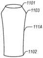
图11-14示出了示例馈通引脚配置,其包括接合装置,该接合装置被配置为一旦预成型导线的近端被放置在馈通引脚上方并被压到馈通引脚上,则保持预成型导线的近端。11-14 illustrate example feedthrough pin configurations that include engagement means configured such that once the proximal end of the preformed wire is placed over the feedthrough pin and pressed onto the feedthrough pin, The proximal end of the preformed lead remains.
图11示出了示例第三短截线馈通引脚111A,其具有直径较小的顶部1101(例如,小于预成型导线的近端的匝),在再次朝向底部1102减小之前朝向上部1103扩展到扩展的直径。顶部1101的较小直径可以有助于将预成型导线(例如,第一预成型导线107A)的近端容易地放置在第三短截线馈通引脚111A上方。第三短截线馈通引脚111A的扩展直径可以大于预成型导线的顶部匝(例如,第一预成型导线107A的第一匝107A1)的直径,使得预成型导线的近端必须被压在第三短截线馈通引脚111A的扩展直径上方,从而将近端保持在第三短截线馈通引脚111A上。在其他示例中,第三短截线馈通引脚111A可以包括在第三短截线馈通引脚111A的顶部和底部之间的多个扩展部分。11 shows an example third
图12示出了示例第四短截线馈通引脚112A,其在顶部1201和底部1202之间具有第一、第二和第三凹陷1203、1204、1205,该凹陷被配置为匹配预成型导线的轮廓,诸如图4的第一预成型导线107A。在某些示例中,第四短截线馈通引脚112A可以具有第三角度θ3,在某些示例中对应于图4中的第一预成型导线107A的第一角度θ1。在其他示例中,第三角度θ3可以比图4中的第一角度θ1浅,使得当第一预成型导线107A的近端被放置在第四短截线馈通引脚112A上方时,第一预成型导线107A的顶部匝(例如,第一匝107A1)接触第四短截线馈通引脚112A的第一凹陷1203。Figure 12 shows an example fourth
图13示出了示例第五短截线馈通引脚113A,其顶部1301和底部1302具有比中心部分1303更大的直径。在某些示例中,一旦放置在其上方,第五短截线馈通引脚113A的形状可以保持预成型导线(例如,第一预成型导线107A)的近端,同时也将预成型导线的近端与连接器块或外壳分离。在其他示例中,顶部1301可以包括类似于图11中所示的顶部1101的轮廓,诸如有助于预成型导线的近端在朝向上部1103的扩展直径上方的初始放置。FIG. 13 shows an example fifth
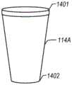
图14示出了示例第六短截线馈通引脚114A,其顶部1401的直径大于底部1402的直径。在一个示例中,预成型导线的顶部匝(例如,第一预成型导线107A的第一匝107A1)可以具有比第六短截线馈通引脚114A的顶部1401更小的直径,使得一旦近端被放置在其上方,第六短截线馈通引脚的形状保持预成型导线的近端。FIG. 14 shows an example sixth
各种实施例如上图所示。来自这些实施例中的一个或多个的一个或多个特征可以被组合以形成其他实施例。本文描述的方法示例可以至少部分地由机器或计算机实施。一些示例可以包括编码有指令的计算机可读介质或机器可读介质,该指令可操作以配置电子设备或系统以执行上述示例中描述的方法。这种方法的实施方式可以包括代码,诸如微码、汇编语言代码、高级语言代码等。这种代码可以包括用于执行各种方法的计算机可读指令。代码可以形成计算机程序产品的一部分。此外,代码可以在执行期间或在其他时间被有形地存储在一个或多个易失性或非易失性计算机可读介质上。Various embodiments are shown in the figure above. One or more features from one or more of these embodiments may be combined to form other embodiments. Method examples described herein may be at least partially implemented by a machine or computer. Some examples may include a computer-readable medium or machine-readable medium encoded with instructions operable to configure an electronic device or system to perform the methods described in the above examples. Implementations of such methods may include code, such as microcode, assembly language code, high-level language code, or the like. Such code may include computer readable instructions for performing various methods. The code may form part of a computer program product. Additionally, the code may be tangibly stored on one or more volatile or non-volatile computer-readable media during execution or at other times.
上述详细描述旨在说明,而非限制。因此,本公开的范围应当参考所附权利要求以及这些权利要求所享有的等同物的全部范围来确定。The foregoing detailed description is intended to be illustrative, not limiting. The scope of the present disclosure, therefore, should be determined with reference to the appended claims, along with the full scope of equivalents to which such claims are entitled.
Claims (15)
Translated fromChineseApplications Claiming Priority (3)
| Application Number | Priority Date | Filing Date | Title |
|---|---|---|---|
| US202063072371P | 2020-08-31 | 2020-08-31 | |
| US63/072,371 | 2020-08-31 | ||
| PCT/US2021/047088WO2022046604A1 (en) | 2020-08-31 | 2021-08-23 | Preformed wire routes in a header of an implantable medical device |
Publications (1)
| Publication Number | Publication Date |
|---|---|
| CN115885433Atrue CN115885433A (en) | 2023-03-31 |
Family
ID=77775003
Family Applications (1)
| Application Number | Title | Priority Date | Filing Date |
|---|---|---|---|
| CN202180052748.4APendingCN115885433A (en) | 2020-08-31 | 2021-08-23 | Preformed wire routing in manifolds for implantable medical devices |
Country Status (4)
| Country | Link |
|---|---|
| US (1) | US12053637B2 (en) |
| EP (1) | EP4204079B1 (en) |
| CN (1) | CN115885433A (en) |
| WO (1) | WO2022046604A1 (en) |
Cited By (1)
| Publication number | Priority date | Publication date | Assignee | Title |
|---|---|---|---|---|
| US12053637B2 (en) | 2020-08-31 | 2024-08-06 | Cardiac Pacemakers, Inc. | Preformed wire routes |
Family Cites Families (16)
| Publication number | Priority date | Publication date | Assignee | Title |
|---|---|---|---|---|
| GB2124495B (en)* | 1982-07-27 | 1986-10-15 | Telectronics Pty Ltd | Prosthetic package and method of making same |
| JPH0637811U (en)* | 1992-10-19 | 1994-05-20 | 旭光学工業株式会社 | Camera shading device |
| US5535097A (en)* | 1993-11-23 | 1996-07-09 | Medtronic, Inc. | Implantable medical device including a first enclosure portion having a feedthrough in a second interior surface |
| US7214107B2 (en)* | 2004-11-22 | 2007-05-08 | Cardiodynamics International Corporation | Electrical connector apparatus and methods |
| US7489968B1 (en)* | 2006-04-07 | 2009-02-10 | Pacesetter, Inc. | Pre-molded header with universal tip-to-tip feedthru adaptor |
| US8162684B1 (en)* | 2008-08-07 | 2012-04-24 | Jerzy Roman Sochor | Implantable connector with contact-containing feedthrough pins |
| WO2011115719A1 (en)* | 2010-03-19 | 2011-09-22 | Cardiac Pacemakers, Inc. | Feedthrough system for implantable device components |
| US9722334B2 (en)* | 2010-04-07 | 2017-08-01 | Black & Decker Inc. | Power tool with light unit |
| US20140141661A1 (en)* | 2011-05-06 | 2014-05-22 | Andreas Veigel | Electrical contact element |
| US8754735B2 (en)* | 2012-04-30 | 2014-06-17 | Honeywell International Inc. | High temperature electromagnetic coil assemblies including braided lead wires and methods for the fabrication thereof |
| AU2014327120B2 (en)* | 2013-09-27 | 2017-01-12 | Cardiac Pacemakers, Inc. | Labeled implantable medical devices |
| US9907965B2 (en)* | 2014-12-30 | 2018-03-06 | Medtronic, Inc. | Implantable medical devices with header structures including conductive paths that facilitate the interconnection of feedthrough conductors to electrical connectors |
| US11896835B2 (en)* | 2017-10-25 | 2024-02-13 | Cochlear Limited | Electrical shielding in implantable medical devices |
| US10603497B2 (en)* | 2017-12-01 | 2020-03-31 | Pacesetter, Inc. | Inverted E-antenna for implantable medical devices |
| US11691019B2 (en)* | 2019-04-15 | 2023-07-04 | Pacesetter, Inc. | Quadripolar header connector support for pre-molded header of implantable pulse generator |
| CN115885433A (en) | 2020-08-31 | 2023-03-31 | 心脏起搏器股份公司 | Preformed wire routing in manifolds for implantable medical devices |
- 2021
- 2021-08-23CNCN202180052748.4Apatent/CN115885433A/enactivePending
- 2021-08-23EPEP21770370.1Apatent/EP4204079B1/enactiveActive
- 2021-08-23USUS17/408,931patent/US12053637B2/enactiveActive
- 2021-08-23WOPCT/US2021/047088patent/WO2022046604A1/ennot_activeCeased
Cited By (1)
| Publication number | Priority date | Publication date | Assignee | Title |
|---|---|---|---|---|
| US12053637B2 (en) | 2020-08-31 | 2024-08-06 | Cardiac Pacemakers, Inc. | Preformed wire routes |
Also Published As
| Publication number | Publication date |
|---|---|
| EP4204079A1 (en) | 2023-07-05 |
| EP4204079B1 (en) | 2025-08-13 |
| US20220062648A1 (en) | 2022-03-03 |
| WO2022046604A1 (en) | 2022-03-03 |
| US12053637B2 (en) | 2024-08-06 |
Similar Documents
| Publication | Publication Date | Title |
|---|---|---|
| US8055354B2 (en) | Interconnections of implantable lead conductors and electrodes and reinforcement therefor | |
| US5666958A (en) | Interface module for electrically connecting medical equipment | |
| US8204596B2 (en) | Isolation connector for an intravascular implantable medical device | |
| US5330522A (en) | Ring electrode for a multilumen lead and method of constructing a multilumen lead | |
| EP2529790A1 (en) | Feedthrough wire connector for use in a medical device | |
| US10587073B2 (en) | Circuit board having a feedthrough wire connector for use in a medical device | |
| JP6640256B2 (en) | Implantable medical device | |
| US8706228B2 (en) | Electronic module assembly for filtered feedthroughs | |
| US8103358B2 (en) | Mapping guidelet | |
| US11564605B2 (en) | Method of manufacturing a lead for an active implantable medical device with a chip for electrode multiplexing | |
| US20080183225A1 (en) | Orientation-independent implantable electrode arrays | |
| WO2003023907A1 (en) | Connector module having internal weld plates | |
| EP3973909A1 (en) | Circular navigation catheter with surface mounted inductive navigation sensors | |
| US20080183235A1 (en) | Insulative shroud for plate-type electrodes adapted for chronic implantation | |
| US20080243195A1 (en) | Mapping guidelet | |
| CN115885433A (en) | Preformed wire routing in manifolds for implantable medical devices | |
| US20080161898A1 (en) | Mapping guidelet | |
| JP4914094B2 (en) | Shielded distance telemetry pin wiring for active implantable medical devices | |
| US20080234591A1 (en) | Methods and apparatus for patient notification of physiologic events and device function | |
| US20250235158A1 (en) | Continuous electrical trace in intraluminal device and associated devices, systems, and methods | |
| US20250121200A1 (en) | Hermetic connector stacks for an electrical stimulation system | |
| US20240278026A1 (en) | Lead insertion verification | |
| US20080183234A1 (en) | Shroud for plate-type electrodes adapted for chronic implantation surrounding implantable medical devices | |
| CN120603626A (en) | IMD with ceramic housing | |
| WO2024256152A1 (en) | Sensor mount for intravascular device with integrated conductive pads for electrical connection to sensor |
Legal Events
| Date | Code | Title | Description |
|---|---|---|---|
| PB01 | Publication | ||
| PB01 | Publication | ||
| SE01 | Entry into force of request for substantive examination | ||
| SE01 | Entry into force of request for substantive examination |