CN115876761A - Optical simulation detection device and sample analyzer - Google Patents
Optical simulation detection device and sample analyzerDownload PDFInfo
- Publication number
- CN115876761A CN115876761ACN202111146559.1ACN202111146559ACN115876761ACN 115876761 ACN115876761 ACN 115876761ACN 202111146559 ACN202111146559 ACN 202111146559ACN 115876761 ACN115876761 ACN 115876761A
- Authority
- CN
- China
- Prior art keywords
- optical assembly
- detection
- sub
- optical
- sample analyzer
- Prior art date
- Legal status (The legal status is an assumption and is not a legal conclusion. Google has not performed a legal analysis and makes no representation as to the accuracy of the status listed.)
- Pending
Links
Images


Landscapes
- Investigating Or Analysing Materials By Optical Means (AREA)
Abstract
Description
Translated fromChinese技术领域technical field
本申请涉及样本分析技术领域,特别涉及一种光学模拟检测装置及样本分析仪。The present application relates to the technical field of sample analysis, in particular to an optical analog detection device and a sample analyzer.
背景技术Background technique
现有的样本分析仪在生产调试或出货检测时都需要使用标准样本进行光学检测,进而浪费大量的试剂。另外,现有的样本分析仪通常使用单人份的试剂盒进行调试或者测试,在每一次调试或测试时,都会消耗一个一次性的试剂盒和一定量的试剂,增加生产制造成本。Existing sample analyzers need to use standard samples for optical detection during production debugging or shipment testing, thereby wasting a lot of reagents. In addition, the existing sample analyzers usually use a single-serving kit for debugging or testing, and each debugging or testing will consume a disposable kit and a certain amount of reagents, increasing the manufacturing cost.
发明内容Contents of the invention
本申请提供一种光学模拟检测装置及样本分析仪,以解决现有技术中,每一次对样本分析仪进行调试或测试时,都会消耗一个一次性的试剂盒和一定量的试剂,增加生产制造成本的技术问题。This application provides an optical analog detection device and a sample analyzer to solve the problem that in the prior art, each time the sample analyzer is debugged or tested, a disposable kit and a certain amount of reagents will be consumed, which increases the cost of production. cost technical issues.
为解决上述技术问题,本申请采用的一个技术方案是:提供一种光学模拟检测装置,应用于样本分析仪,该检测装置包括:光学组件,设置于样本分析仪的光源发射器的出光光路上,光学组件用于对光源发射器发出的光束进行处理,以形成模拟检测信号,模拟检测信号用于样本分析仪的检测分析,以得到检测结果。In order to solve the above technical problems, a technical solution adopted by this application is to provide an optical analog detection device, which is applied to the sample analyzer, and the detection device includes: an optical component, which is arranged on the light output path of the light source emitter of the sample analyzer , the optical component is used to process the light beam emitted by the light source transmitter to form an analog detection signal, and the analog detection signal is used for detection and analysis of the sample analyzer to obtain a detection result.
进一步地,光学组件为滤光组件,滤光组件用于从光束中选择预设波长的光,以形成模拟检测信号。Further, the optical component is a filter component, and the filter component is used to select light with a preset wavelength from the light beam to form an analog detection signal.
进一步地,滤光组件设置成从光束中选择波长范围为520nm-540nm的光,以形成HGB检测的模拟检测信号。Further, the filter assembly is configured to select light with a wavelength range of 520nm-540nm from the light beam to form an analog detection signal for HGB detection.
进一步地,滤光组件为玻璃片、塑料片或者内部封装有质控品的片体。Further, the filter assembly is a glass sheet, a plastic sheet or a sheet with a quality control product inside.
进一步地,光学组件为散射组件,散射组件用于使光源发射器发出的光束发生散射,以形成模拟检测信号。Further, the optical component is a scattering component, and the scattering component is used to scatter the light beam emitted by the light source emitter to form an analog detection signal.
进一步地,散射组件设置成使光束的偏转角度为20°-90°,以形成特定蛋白的模拟检测信号。Further, the scattering component is set so that the deflection angle of the light beam is 20°-90°, so as to form an analog detection signal of a specific protein.
进一步地,散射组件为磨砂玻璃片、塑料片或者内部封装有质控品的片体。Further, the scattering component is a ground glass sheet, a plastic sheet, or a sheet with a quality control product packaged inside.
进一步地,样本分析仪的项目检测包括样本检测和本底检测,光学组件包括第一子光学组件和第二子光学组件,光源发射器发出的光束通过第一子光学组件,产生样本检测的模拟检测信号,光源发射器发出的光束通过第二子光学组件,产生本底检测的模拟检测信号;检测装置还包括驱动机构,驱动机构连接光学组件,用于驱动光学组件运动,以使第一子光学组件和第二子光学组件分别移动至光源发射器的出光光路上。Further, the item detection of the sample analyzer includes sample detection and background detection. The optical assembly includes a first sub-optical assembly and a second sub-optical assembly. The light beam emitted by the light source emitter passes through the first sub-optical assembly to generate a simulation of sample detection. For the detection signal, the light beam emitted by the light source emitter passes through the second sub-optical assembly to generate an analog detection signal for background detection; the detection device also includes a driving mechanism, which is connected to the optical assembly and is used to drive the optical assembly to move so that the first sub-optical assembly The optical assembly and the second sub-optical assembly are respectively moved to the light-emitting optical path of the light source emitter.
进一步地,第一子光学组件和第二子光学组件弯折连接,驱动机构用于驱动光学组件旋转,以使第一子光学组件和第二子光学组件分别移动至光源发射器的出光光路上。Further, the first sub-optical assembly and the second sub-optical assembly are bent and connected, and the driving mechanism is used to drive the optical assembly to rotate, so that the first sub-optical assembly and the second sub-optical assembly can move to the light output optical path of the light source emitter respectively .
进一步地,第一子光学组件和第二子光学组件沿竖直方向并排连接,驱动机构用于驱动光学组件沿竖直方向运动,以使第一子光学组件和第二子光学组件分别移动至光源发射器的出光光路上。Further, the first sub-optical assembly and the second sub-optical assembly are connected side by side in the vertical direction, and the drive mechanism is used to drive the optical assembly to move in the vertical direction, so that the first sub-optical assembly and the second sub-optical assembly move to The output light path of the light source emitter.
进一步地,第一子光学组件和第二子光学组件沿水平方向并排连接,驱动机构用于驱动光学组件沿水平方向运动,以使第一子光学组件和第二子光学组件分别移动至光源发射器的出光光路上。Further, the first sub-optical assembly and the second sub-optical assembly are connected side by side in the horizontal direction, and the driving mechanism is used to drive the optical assembly to move in the horizontal direction, so that the first sub-optical assembly and the second sub-optical assembly move to the light source to emit on the light output path of the device.
进一步地,检测装置还包括转盘,第一子光学组件和第二子光学组件设置于转盘上,并沿转盘的周向排布,驱动机构连接转盘,并用于驱动转盘转动,以使第一子光学组件和第二子光学组件分别移动至光源发射器的出光光路上。Further, the detection device also includes a turntable, the first sub-optical assembly and the second sub-optical assembly are arranged on the turntable, and arranged along the circumference of the turntable, the driving mechanism is connected to the turntable, and is used to drive the turntable to rotate, so that the first sub-optical assembly The optical assembly and the second sub-optical assembly are respectively moved to the light-emitting optical path of the light source emitter.
进一步地,转盘上还设置有若干个沿转盘周向排布的通孔,通孔用于使光源发射器发出的光束穿过,以对实际样本进行检测。Further, the turntable is also provided with several through holes arranged along the circumference of the turntable, and the through holes are used for passing the light beam emitted by the light source emitter to detect the actual sample.
为解决上述技术问题,本申请采用的另一个技术方案是:提供一种样本分析仪的检测方法,该检测方法应用于上述任一实施例的光学模拟检测装置,该检测方法包括:样本分析仪的光源发射器发出光束;检测装置的光学组件对光束进行处理,形成模拟检测信号;样本分析仪接收模拟检测信号,并基于模拟检测信号进行检测,得到检测结果;样本分析仪判断检测结果是否在预设的范围内;若是,则确认样本分析仪工作正常。In order to solve the above technical problems, another technical solution adopted by this application is to provide a detection method for a sample analyzer, which is applied to the optical analog detection device of any of the above embodiments, and the detection method includes: a sample analyzer The light source emitter emits a light beam; the optical components of the detection device process the light beam to form an analog detection signal; the sample analyzer receives the analog detection signal, and performs detection based on the analog detection signal to obtain the detection result; the sample analyzer judges whether the detection result is in the within the preset range; if so, confirm that the sample analyzer is working properly.
为解决上述技术问题,本申请采用的又一个技术方案是:提供一种样本分析仪,该样本分析仪包括检测座和上述任一实施例的光学模拟检测装置,光学模拟检测装置设置于检测座上,用于进行光学模拟检测。In order to solve the above technical problems, another technical solution adopted by this application is to provide a sample analyzer, which includes a detection seat and the optical analog detection device of any of the above-mentioned embodiments, and the optical analog detection device is arranged on the detection seat on, for optical analog testing.
为解决上述技术问题,本申请采用的再一个技术方案是:提供一种便携式血细胞分析仪,该便携式血细胞分析仪包括检测座和上述任一实施例的光学模拟检测装置,光学模拟检测装置设置于检测座上,用于进行光学模拟检测。In order to solve the above technical problems, another technical solution adopted by this application is to provide a portable blood cell analyzer, which includes a detection base and the optical analog detection device of any of the above-mentioned embodiments, and the optical analog detection device is set on On the detection seat, it is used for optical analog detection.
本申请的有益效果是:区别于现有技术的情况,本申请的光学模拟检测装置包括光学组件,光学组件用于对样本分析仪的光源发射器发出的光束进行处理,以形成模拟检测信号,模拟检测信号用于样本分析仪的检测分析,以得到检测结果,当样本分析仪确认检测结果在预设的范围内时,则可确认样本分析仪工作正常。本申请中,通过检测装置中的光学组件输出模拟检测信号,样本分析仪基于该模拟检测信号进行检测,以对样本分析仪进行调试或测试,无需使用标准样本,避免试剂盒和试剂的浪费,降低生产制造成本。The beneficial effects of the present application are: different from the situation in the prior art, the optical analog detection device of the present application includes an optical component, and the optical component is used to process the light beam emitted by the light source emitter of the sample analyzer to form an analog detection signal, The analog detection signal is used for detection and analysis of the sample analyzer to obtain a detection result. When the sample analyzer confirms that the detection result is within a preset range, it can be confirmed that the sample analyzer is working normally. In this application, the analog detection signal is output by the optical components in the detection device, and the sample analyzer performs detection based on the analog detection signal to debug or test the sample analyzer, without using standard samples and avoiding the waste of kits and reagents. Reduce production and manufacturing costs.
附图说明Description of drawings
为了更清楚地说明本申请实施例中的技术方案,下面将对实施例描述中所需要使用的附图作简单地介绍,显而易见地,下面描述中的附图仅仅是本申请的一些实施例,对于本领域普通技术人员来讲,在不付出创造性劳动的前提下,还可以根据这些附图获得其他的附图,其中:In order to more clearly illustrate the technical solutions in the embodiments of the present application, the drawings that need to be used in the description of the embodiments will be briefly introduced below. Obviously, the drawings in the following description are only some embodiments of the present application. For those of ordinary skill in the art, other drawings can also be obtained based on these drawings without creative work, in which:
图1是本申请提供的光学模拟检测装置的一实施例的结构示意图;Fig. 1 is a schematic structural view of an embodiment of an optical analog detection device provided by the present application;
图2是图1所示的光学组件的一实施例的结构示意图;Fig. 2 is a schematic structural view of an embodiment of the optical assembly shown in Fig. 1;
图3是图1所示的光学组件的另一实施例的结构示意图;Fig. 3 is a schematic structural view of another embodiment of the optical assembly shown in Fig. 1;
图4是图1所述的光学组件的又一实施例的结构示意图;Fig. 4 is a schematic structural view of another embodiment of the optical assembly described in Fig. 1;
图5是图1所示的光学组件的再一实施例的结构示意图;Fig. 5 is a schematic structural view of yet another embodiment of the optical assembly shown in Fig. 1;
图6是本申请提供的光学模拟检测装置的另一实施例的结构示意图;Fig. 6 is a schematic structural view of another embodiment of the optical analog detection device provided by the present application;
图7是本申请提供的光学模拟检测装置的又一实施例的结构示意图;Fig. 7 is a schematic structural diagram of another embodiment of the optical analog detection device provided by the present application;
图8是图7所示的散射组件的光路示意图;Fig. 8 is a schematic diagram of the optical path of the scattering assembly shown in Fig. 7;
图9是本申请提供的光学模拟检测装置的再一实施例的结构示意图;Fig. 9 is a schematic structural view of yet another embodiment of the optical analog detection device provided by the present application;
图10是本申请提供的样本分析仪的检测方法的一实施例的流程示意图;Fig. 10 is a schematic flow chart of an embodiment of the detection method of the sample analyzer provided by the present application;
图11是本申请提供的样本分析仪的一实施例的结构示意图。Fig. 11 is a schematic structural diagram of an embodiment of the sample analyzer provided by the present application.
具体实施方式Detailed ways
下面将结合本申请实施例中的附图,对本申请实施例中的技术方案进行清楚、完整地描述,显然,所描述的实施例仅是本申请的一部分实施例,而不是全部的实施例。基于本申请中的实施例,本领域普通技术人员在没有做出创造性劳动前提下所获得的所有其他实施例,都属于本申请保护的范围。The following will clearly and completely describe the technical solutions in the embodiments of the present application with reference to the accompanying drawings in the embodiments of the present application. Obviously, the described embodiments are only part of the embodiments of the present application, not all of them. Based on the embodiments in this application, all other embodiments obtained by persons of ordinary skill in the art without making creative efforts belong to the scope of protection of this application.
需要说明,若本申请实施例中有涉及方向性指示(诸如上、下、左、右、前、后……),则该方向性指示仅用于解释在某一特定姿态(如附图所示)下各部件之间的相对位置关系、运动情况等,如果该特定姿态发生改变时,则该方向性指示也相应地随之改变。It should be noted that if there are directional indications (such as up, down, left, right, front, back...) in the embodiment of the present application, the directional indications are only used to explain the position in a certain posture (as shown in the accompanying drawings). If the specific posture changes, the directional indication will also change accordingly.
另外,若本申请实施例中有涉及“第一”、“第二”等的描述,则该“第一”、“第二”等的描述仅用于描述目的,而不能理解为指示或暗示其相对重要性或者隐含指明所指示的技术特征的数量。由此,限定有“第一”、“第二”的特征可以明示或者隐含地包括至少一个该特征。另外,各个实施例之间的技术方案可以相互结合,但是必须是以本领域普通技术人员能够实现为基础,当技术方案的结合出现相互矛盾或无法实现时应当认为这种技术方案的结合不存在,也不在本申请要求的保护范围之内。In addition, if there are descriptions involving "first", "second", etc. in the embodiments of the present application, the descriptions of "first", "second", etc. are only for descriptive purposes, and cannot be interpreted as indications or hints Its relative importance or implicitly indicates the number of technical features indicated. Thus, the features defined as "first" and "second" may explicitly or implicitly include at least one of these features. In addition, the technical solutions of the various embodiments can be combined with each other, but it must be based on the realization of those skilled in the art. When the combination of technical solutions is contradictory or cannot be realized, it should be considered that the combination of technical solutions does not exist , nor within the scope of protection required by the present application.
样本分析仪是常用的医用检测设备,用于对样本进行分析检测。样本可以为血液或者尿液等生物样本。比如,样本分析仪通过对血液样本进行检测分析,以对被检样本进行血液性疾病、贫血等疾病的诊断。常见的样本分析仪有血细胞分析仪,例如,POCT(point-of-care testing,即时检验)血细胞分析仪。A sample analyzer is a commonly used medical testing device for analyzing and testing samples. The sample can be a biological sample such as blood or urine. For example, the sample analyzer detects and analyzes blood samples to diagnose blood diseases, anemia and other diseases on the tested samples. Common sample analyzers include blood cell analyzers, for example, POCT (point-of-care testing, point-of-care testing) blood cell analyzers.
样本分析仪对样本进行检测时,比较常用的检测方法包括光学检测法。比如,采用比色法和散射比浊法对样本进行分析检测。When the sample analyzer detects the sample, the commonly used detection methods include the optical detection method. For example, colorimetry and turbidimetry are used to analyze and detect samples.
比色法检测的原理为:被测试样本浓度的改变,改变了样本颜色的深浅。样本浓度越高,样本的颜色就越深,反之,如果样本的浓度越低,颜色就越浅。颜色的深浅直接影响了样本对光线的吸收程度。样本颜色越深,吸收的光线越多,透过的光线越少。反之,样本颜色越浅,吸收的光线越少,透过的光线越多。因此,通过测量透过检测池光线的强弱,可以间接测量出样本的浓度。在一个实施例中,样本分析仪可以通过比色法对样本进行HGB(haemoglobin,血红蛋白)检测。在其他实施例中,样本分析仪还可以通过比色法对样本进行HCY(Homocysteine,同型半胱氨酸)检测或者一氧化氮浓度的检测等。The principle of colorimetric detection is: the change of the concentration of the tested sample changes the depth of the color of the sample. The higher the concentration of the sample, the darker the color of the sample, conversely, the lighter the color of the sample if the concentration of the sample is lower. The depth of the color directly affects the degree to which the sample absorbs light. The darker the sample, the more light is absorbed and the less light is transmitted. Conversely, the lighter the color of the sample, the less light is absorbed and more light is transmitted. Therefore, by measuring the intensity of light passing through the detection cell, the concentration of the sample can be indirectly measured. In one embodiment, the sample analyzer can perform HGB (haemoglobin, hemoglobin) detection on the sample by a colorimetric method. In other embodiments, the sample analyzer can also perform HCY (Homocysteine, homocysteine) detection or nitric oxide concentration detection on the sample through a colorimetric method.
散射比浊法检测的原理为:当一定波长的光沿水平轴照射,通过样本溶液时遇到粒子,光线被粒子颗粒折射,发生偏转,光线偏转的角度与发射光的波长和粒子大小和多少密切相关。散射比浊法测定的光信号就是散射光,其强弱与样本浓度成正比。在一个实施例中,样本分析仪可以通过散射比浊法对样本进行特定蛋白检测。在其他实施例中,样本分析仪还可以通过散射比浊法对样本进行其他项目的检测。The principle of scattering turbidimetry detection is: when light of a certain wavelength is irradiated along the horizontal axis and encounters particles when passing through the sample solution, the light is refracted by the particles and deflected, and the angle of light deflection is related to the wavelength of the emitted light and the size of the particles closely related. The light signal measured by nephelometry is scattered light, and its strength is directly proportional to the sample concentration. In one embodiment, the sample analyzer can perform specific protein detection on the sample by turbidimetry. In other embodiments, the sample analyzer can also detect other items of the sample by turbidimetry.
本申请提供一种光学模拟检测装置,用于输出模拟检测信号,以通过模拟检测信号等效于光束穿过检测池中的样本后产生的检测信号。The present application provides an optical analog detection device, which is used to output an analog detection signal, so that the analog detection signal is equivalent to the detection signal generated after the light beam passes through the sample in the detection cell.
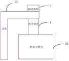
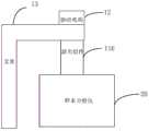
具体地,请参阅图1所示,图1是本申请提供的光学模拟检测装置的一实施例的结构示意图。该光学模拟检测装置包括光学组件11,光学组件11用于对样本分析仪20的光源发射器(图未示)发出的光束进行处理,以形成模拟检测信号,模拟检测信号用于样本分析仪20的检测分析,以得到检测结果。当检测结果在预设的范围内时,则可确认样本分析仪20工作正常,当检测结果不在预设的范围内时,则可确认样本分析仪20工作异常,需要对样本分析仪20进行调试。Specifically, please refer to FIG. 1 , which is a schematic structural diagram of an embodiment of an optical analog detection device provided by the present application. The optical analog detection device includes an
上述实施例中,检测装置通过光学组件11输出模拟检测信号,以通过该模拟检测信号等效于光束穿过检测池后产生的检测信号。本申请的检测装置对样本分析仪20进行检测时,无需使用标准样本,避免试剂和试剂盒的浪费,降低生产制造成本。In the above embodiments, the detection device outputs an analog detection signal through the
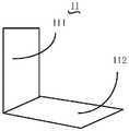
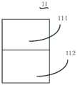
如图2-5所示,图2是图1所示的光学组件的一实施例的结构示意图,图3是图1所示的光学组件的另一实施例的结构示意图,图4是图1所示的光学组件的又一实施例的结构示意图,图5是图1所示的光学组件的再一实施例的结构示意图,光学组件11用于对样本分析仪20进行光学模拟检测,光学组件11可以包括第一子光学组件111和第二子光学组件112。As shown in Figures 2-5, Figure 2 is a schematic structural view of an embodiment of the optical assembly shown in Figure 1, Figure 3 is a schematic structural view of another embodiment of the optical assembly shown in Figure 1, and Figure 4 is a schematic structural view of an embodiment of the optical assembly shown in Figure 1 A schematic structural view of another embodiment of the optical assembly shown in FIG. 5 is a schematic structural view of another embodiment of the optical assembly shown in FIG. 11 may include a first
进一步地,样本分析仪的项目检测包括样本检测和本底检测,其中,本底检测指的是未添加样本时,对检测池进行的检测,样本检测指的是在检测池中添加了样本后进行的检测。Further, the item detection of the sample analyzer includes sample detection and background detection, wherein, the background detection refers to the detection of the detection pool when no sample is added, and the sample detection refers to the detection after the sample is added to the detection pool. tests performed.
样本分析仪20的光源发射器发出的光束通过第一子光学组件111,产生样本检测的模拟信号,样本分析仪20的光源发射器发出的光束通过第二子光学组件112,产生本底检测的模拟信号。样本分析仪20基于样本检测的模拟信号和本底检测的模拟信号,得到检测结果,当检测结果在预设的范围内时,则可确认样本分析仪20工作正常,当检测结果不在预设的范围内时,则可确认样本分析仪20工作异常,需要进行调试。The light beam emitted by the light source transmitter of the
上述实施例中,通过使用两个子光学组件(第一子光学组件111和第二子光学组件112)分别模拟本底检测和样本检测,检测过程简单,且避免浪费试剂盒和试剂,节约样本分析仪20测试和调试的成本。两个子光学组件的材质或者规格可以不同,以适应不同场景的模拟检测。In the above-mentioned embodiment, by using two sub-optical assemblies (the first
进一步地,如图1所示,检测装置还包括驱动机构12和支架13,驱动机构12位于支架13上,支架13用于承载驱动机构12和光学组件11。Further, as shown in FIG. 1 , the detection device further includes a
驱动机构12连接光学组件11,用于驱动光学组件11运动,以使第一子光学组件111和第二子光学组件112分别移动至光源发射器的出光光路上,以分别模拟本底检测和样本检测。The
驱动机构12可以为电机或者气缸等。驱动机构12的输出端连接光学组件11,以带动光学组件11旋转或者进行直线运动。关于驱动机构12的具体结构为本领域技术人员理解的范畴,在此不做具体介绍。The
可选地,在一个实施例中,如图2所示,第一子光学组件111和第二子光学组件112弯折连接。具体地,第一子光学组件111和第二子光学组件112可以呈“L”型设置,驱动机构12用于驱动光学组件11旋转,以使第一子光学组件111和第二子光学组件112分别移动至光源发射器的出光光路上。即,光学组件11具有第一状态和第二状态,驱动机构12带动光学组件11进行旋转,以使光学组件11在第一状态和第二状态之间进行切换。光学组件11在第一状态时,第一子光学组件111位于光源发射器的出光光路上,以形成样本检测的模拟信号,光学组件11在第二状态时,第二子光学组件112位于光源发射器的出光光路上,以形成本底检测的模拟信号。上述实施例中,将光学组件11设置成“L”型,能够减小光学组件11的整体长度,从而减小光学组件11的占用空间。Optionally, in one embodiment, as shown in FIG. 2 , the first
可选地,在另一个实施例中,如图3所示,第一子光学组件111和第二子光学组件112可以沿竖直方向并排连接,驱动机构12用于驱动光学组件11沿竖直方向运动,以使第一子光学组件111和第二子光学组件112分别移动至光源发射器的出光光路上。即,本实施例中,光学组件11也具有第一状态和第二状态,驱动机构12带动光学组件11沿竖直方向运动,以使光学组件11在第一状态和第二状态之间进行切换。光学组件11在第一状态时,第一子光学组件111位于光源发射器的出光光路上,以形成样本检测的模拟信号,光学组件11在第二状态时,第二子光学组件112位于光源发射器的出光光路上,以形成本底检测的模拟信号。本实施例中,光学组件11的结构简单,且光学组件11的移动过程简单,另外,光学组件11在水平方向的宽度较小,能够减小检测装置在水平方向上占用的空间。Optionally, in another embodiment, as shown in FIG. 3 , the first
可选地,在另一个实施例中,如图4所示,第一子光学组件111和第二子光学组件112沿水平方向并排连接,驱动机构12用于驱动光学组件11沿水平方向运动,以使第一子光学组件111和第二子光学组件112分别移动至光源发射器的出光光路上。本实施例中,光学组件11也具有第一状态和第二状态,驱动机构12带动光学组件11沿水平方向运动,以使光学组件11在第一状态和第二状态之间进行切换。光学组件11在第一状态时,第一子光学组件111位于光源发射器的出光光路上,以形成样本检测的模拟信号,光学组件11在第二状态时,第二子光学组件112位于光源发射器的出光光路上,以形成本底检测的模拟信号。本实施例中,光学组件11的结构简单,光学组件11的移动过程简单,且光学组件11在竖直方向的宽度较小,减小检测装置在竖直方向上占用的空间。Optionally, in another embodiment, as shown in FIG. 4 , the first
如图5和图6所示,在另一个实施例中,检测装置还包括转盘114,光学组件11设置于该转盘114上。具体地,如图6所示,第一子光学组件111和第二子光学组件112设置于转盘114上,并沿转盘114的周向排布。As shown in FIGS. 5 and 6 , in another embodiment, the detection device further includes a
驱动机构12连接转盘114,并用于驱动转盘114转动,以使第一子光学组件111和第二子光学组件112分别移动至光源发射器的出光光路上。The
进一步地,转盘114上还设置有若干个沿转盘114周向排布的通孔113,通孔113用于使光源发射器发出的光束穿过,以对实际样本进行检测。即本实施例中,当需要对样本分析仪20进行检测时,则通过驱动机构12驱动转盘114转动,使第一子光学组件111和第二子光学组件112分别位于光源发射器的出光光路上,以分别形成样本检测的模拟信号和本底检测的模拟信号。当样本分析仪20需要对实际样本进行检测时,驱动机构12驱动转盘114旋转,使通孔113位于光源发射器的出光光路上,光源发射器发出的光束能够从通孔113穿过,以对实际样本进行检测。本实施例中,通过驱动机构12驱动转盘114转动,能够使检测装置对样本分析仪20进行检测,也能使样本分析仪20对实际样本进行检测,无需将检测装置从样本分析仪20中拆出,方便用户使用。Further, the
可以理解的是,也可以根据实际需要将光学组件11分成三个子光学组件、四个子光学组件等,通过驱动机构12使不同的子光学组件分别位于光源发射器的出光光路上,在此不做一一列举。It can be understood that the
可选地,检测装置可以包括光源发射器和光源接收器,光源发射器用于发射光束,光学组件11位于光源发射器的出光光路上,并用于对光源发射器发出的光束进行处理,以形成模拟检测信号,光源接收器用于接收该模拟检测信号,样本分析仪20基于该模拟检测信号进行分析检测,以得到检测结果。本实施例的检测装置包括光源发射器和光源接收器,此种设置方式,能够减小检测装置对样本分析仪20的依赖,提高检测装置的适用性。Optionally, the detection device may include a light source emitter and a light source receiver, the light source emitter is used to emit light beams, the
可选地,检测装置也可以不包括光源发射器和光源接收器,而是直接使用样本分析仪20中的光源系统,具体地,样本分析仪20的光源发射器发出光束,光学组件11位于光源发射器的出光光路上,并用于对光源发射器发出的光束进行处理,以形成模拟检测信号,样本分析仪20的光源接收器接收该模拟检测信号,以用于样本分析仪20的检测分析,得到检测结果。该检测结果在预设范围内时,确认样本分析仪20能够正常工作。此种设置方式,能够简化检测装置的结构,充分利用样本分析仪20中现有的光源系统进行模拟检测,节约检测成本。Optionally, the detection device may not include a light source emitter and a light source receiver, but directly use the light source system in the
综上所述,上述实施例中,检测装置的结构简单,能够通过检测装置对样本分析仪20进行检测分析,无需使用标准样本,且能够避免试剂盒和试剂的浪费,节约成本。To sum up, in the above embodiment, the detection device has a simple structure, and the
在一具体的实施例中,如图1、图7和图8所示,光学组件11可以为散射组件115,散射组件115用于使光源发射器发出的光束发生散射,以形成模拟检测信号,模拟检测信号用于样本分析仪20的检测分析,以得到检测结果。In a specific embodiment, as shown in FIG. 1, FIG. 7 and FIG. 8, the
进一步地,散射组件115可以设置成使光束的偏转角度为20°-90°光,以形成特定蛋白的模拟检测信号。比如,散射组件115可以设置成使光束的偏转角度为20°、30°、40°、50°、60°或者90°等,如此,能够通过散射组件115模拟特定蛋白检测,并形成特定蛋白检测的模拟检测信号,无需使用血液样本,且能够避免试剂和试剂盒的浪费,降低生产制造成本。在其他实施例中,也可以通过散射组件115模拟其他项目的检测,以形成模拟检测信号,只要通过散射比浊法检测的项目均可。Further, the
进一步地,散射组件115可以为磨砂玻璃片、塑料片或者内部封装有质控品的片体。本实施例中,内部封装有质控品的片体具体为一片体且该片体内封装有质控品。进一步地,片体可以为透明片体,质控品可以为实际反应后的样本或者为一种可以使光束发生散射的悬浊液。散射组件115成本较低,能够降低检测装置的成本。Further, the
本实施例中,散射组件115也可以包括第一子散射组件和第二子散射组件,其中第一子散射组件可以为上述实施例的第一子光学组件111,第二散射组件可以为上述的实施例的第二子光学组件112。关于散射组件115的结构方式以及运动过程可以参考上述实施例中光学组件11的结构和运动过程,在此不再赘述。In this embodiment, the
本实施例中,光学组件11为散射组件115,能够模拟特定蛋白等项目的检测,检测过程简单,且无需使用标准样本,能够避免试剂和试剂盒的浪费,检测成本较低。In this embodiment, the
在另一具体的实施例中,如图1和图9所示,光学组件11可以为滤光组件116,滤光组件116用于从样本分析仪20的光源发射器发射的光束中选择预设波长的光,以形成模拟检测信号,模拟检测信号用于样本分析仪20的检测分析,以得到检测结果。当检测结果在预设的范围内时,则可确认样本分析仪20工作正常,当检测结果不在预设的范围内时,则确认样本分析仪20工作异常,需要对样本分析仪20进行调试。In another specific embodiment, as shown in FIGS. 1 and 9 , the
进一步地,滤光组件116可以设置成从光束中选择波长范围为520nm-540nm光,以形成HGB的模拟检测信号。如此,能够通过滤光组件116模拟HGB(haemoglobin,血红蛋白)光学检测,并形成HGB的模拟检测信号,无需使用血液样本,且能够避免试剂和试剂盒的浪费,降低成本。Further, the
在其他实施例中,也可以根据实际需要将滤光组件116设置成选择其他波长范围的光,具体根据实际检测的项目进行选择设置。In other embodiments, the
进一步地,滤光组件116的半波宽为8nm-12nm,比如,滤光组件116的半波宽为8mm、10nm或者12nm等,或者滤光组件116为窄带滤光组件。Further, the half-wave width of the
进一步地,滤光组件116可以为玻璃片、塑料片或者内部封装有质控品的片体。本实施例中,内部封装有质控品的片体具体为一片体且该片体内封装质控品,其中,片体可以为透明片体,质控品可以为实际反应后的样本或者为一种选择特定波长的光的液体。滤光组件116的成本较低,能够降低检测装置的成本。Further, the
在其他实施例中,滤光组件116可以设置成对其他项目进行模拟检测,比如,对HCY(Homocysteine,同型半胱氨酸)或者一氧化氮浓度的检测等。In other embodiments, the
本实施例中,光学组件11为滤光组件116,能够模拟HGB等项目的检测,检测过程简单,且无需使用标准样本,能够避免试剂和试剂盒的浪费,检测成本较低。In this embodiment, the
请参阅图10所示,图10是本申请提供的样本分析仪的检测方法一实施例的流程示意图。本实施例的检测方法应用于上述实施例所揭示的光学模拟检测装置,该检测方法包括以下步骤:Please refer to FIG. 10 , which is a schematic flowchart of an embodiment of a detection method of a sample analyzer provided in the present application. The detection method of this embodiment is applied to the optical analog detection device disclosed in the above embodiments, and the detection method includes the following steps:
S101:样本分析仪的光源发射器发出光束。S101: The light source emitter of the sample analyzer emits a light beam.
当需要使用检测装置对样本分析仪进行检测时,先将光学组件置于样本分析仪的光源发射器的出光光路上,然后,样本分析仪的光源发射器发出光束,使光束通过光学组件。When it is necessary to use the detection device to detect the sample analyzer, the optical component is first placed on the light output path of the light source emitter of the sample analyzer, and then the light source emitter of the sample analyzer emits a light beam to pass through the optical component.
进一步地,光学组件可以包括第一子光学组件和第二子光学组件,具体请参阅上述实施例的介绍。可以根据检测需要将第一子光学组件或者第二子光学组件置于光源发射器的出光光路上。Further, the optical assembly may include a first sub-optical assembly and a second sub-optical assembly, please refer to the introduction of the foregoing embodiments for details. The first sub-optical assembly or the second sub-optical assembly can be placed on the light output path of the light source emitter according to detection requirements.
S102:光学组件对光束进行处理后,形成模拟检测信号。S102: After the optical component processes the light beam, an analog detection signal is formed.
光源发射器发出的光束经过光学组件,光学组件对光束进行处理,以形成模拟检测信号。The light beam emitted by the light source transmitter passes through the optical component, and the optical component processes the light beam to form an analog detection signal.
具体地,光学组件为滤光组件时,滤光组件对光束进行滤光处理,光学组件为散射组件时,散射组件对光束进行散射处理。其中,滤光组件和散射组件的材质和型号可以根据检测的项目进行选择设置。其中滤光组件可以为玻璃片。散射组件可以为磨砂玻璃片或者塑料片。Specifically, when the optical component is a filter component, the filter component performs light filtering processing on the light beam, and when the optical component is a scattering component, the scattering component performs scattering processing on the light beam. Among them, the material and model of the filter component and the scattering component can be selected and set according to the detected items. Wherein the filter assembly may be a glass sheet. The scattering component can be a frosted glass sheet or a plastic sheet.
S103:样本分析仪接收模拟检测信号,并基于模拟检测信号进行检测,得到检测结果。S103: The sample analyzer receives the analog detection signal, performs detection based on the analog detection signal, and obtains a detection result.
在样本分析仪接收到上述模拟检测信号,并基于该模拟检测信号进行检测,得到检测结果,以对样本分析仪进行调试或测试。The sample analyzer receives the above-mentioned analog detection signal, performs detection based on the analog detection signal, and obtains a detection result, so as to debug or test the sample analyzer.
S104:样本分析仪判断检测结果是否在预设的范围内。S104: The sample analyzer judges whether the detection result is within a preset range.
样本分析仪在得到检测结果后,判断检测结果是否在预设的范围内。预设的范围可以根据模拟检测的项目事先设置。After obtaining the test result, the sample analyzer judges whether the test result is within a preset range. The preset range can be set in advance according to the simulated detection items.
S105:若是,则确认样本分析仪工作正常。S105: If yes, confirm that the sample analyzer works normally.
若样本分析仪确认检测结果在预设的范围内,则确认样本分析仪工作正常。If the sample analyzer confirms that the test result is within the preset range, it is confirmed that the sample analyzer is working normally.
S106:若否,则确认样本分析仪工作异常。S106: If not, confirm that the sample analyzer is working abnormally.
若样本分析仪确认检测结果不在预设的范围内,则确认样本分析仪工作异常,需要对样本分析仪进行调试。If the sample analyzer confirms that the detection result is not within the preset range, it is confirmed that the sample analyzer is working abnormally, and the sample analyzer needs to be debugged.
本申请的样本分析仪的检测过程简单,且无需使用标准样本,避免试剂和试剂盒的浪费,降低生成制造成本。The detection process of the sample analyzer of the present application is simple and does not require the use of standard samples, thereby avoiding waste of reagents and kits and reducing production and manufacturing costs.
请参见图11所示,图11是本申请提供的样本分析仪的一实施例的结构示意图。该样本分析仪30包括检测座32和上述任一实施例的光学模拟检测装置31,光学模拟检测装置31设置于检测座32上,以对样本分析仪30进行光学模拟检测。Please refer to FIG. 11 , which is a schematic structural diagram of an embodiment of a sample analyzer provided by the present application. The
关于光学模拟检测装置31的结构请参阅上述任一实施例的介绍,在此不再赘述。For the structure of the optical
本申请提供的样本分析仪30中,通过光学模拟检测装置31产生模拟检测信号,样本分析仪30基于该模拟检测信号进行检测分析,从而得到检测结果,并在检测结果在预设范围内时,确认样本分析仪30工作正常。通过此种方式,在对样本分析仪30进行检测时,无需使用标准样本,避免试剂的浪费,降低生产制造成本,具有较强的实用性。In the
本申请还提供一种便携式血细胞分析仪,便携式血细胞分析仪是样本分析仪的一种,用于对血液样本进行检测分析。该便携式血细胞分析仪包括检测座和上述任一实施例的光学模拟检测装置,光学模拟检测装置设置于检测座上,用于进行光学模拟检测。The present application also provides a portable blood cell analyzer, which is a type of sample analyzer, and is used for detecting and analyzing blood samples. The portable blood cell analyzer includes a detection seat and the optical analog detection device of any one of the above-mentioned embodiments, and the optical analog detection device is arranged on the detection seat for optical analog detection.
关于光学模拟检测装置的结构请参阅上述任一实施例的介绍,在此不再赘述。For the structure of the optical analog detection device, please refer to the introduction of any of the above-mentioned embodiments, which will not be repeated here.
以上仅为本申请的实施方式,并非因此限制本申请的专利范围,凡是利用本申请说明书及附图内容所作的等效结构或等效流程变换,或直接或间接运用在其它相关的技术领域,均同理包括在本申请的专利保护范围内。The above is only the implementation mode of this application, and does not limit the scope of patents of this application. Any equivalent structure or equivalent process conversion made by using the contents of this application specification and drawings, or directly or indirectly used in other related technical fields, All are included in the scope of patent protection of the present application in the same way.
Claims (16)
Priority Applications (1)
| Application Number | Priority Date | Filing Date | Title |
|---|---|---|---|
| CN202111146559.1ACN115876761A (en) | 2021-09-28 | 2021-09-28 | Optical simulation detection device and sample analyzer |
Applications Claiming Priority (1)
| Application Number | Priority Date | Filing Date | Title |
|---|---|---|---|
| CN202111146559.1ACN115876761A (en) | 2021-09-28 | 2021-09-28 | Optical simulation detection device and sample analyzer |
Publications (1)
| Publication Number | Publication Date |
|---|---|
| CN115876761Atrue CN115876761A (en) | 2023-03-31 |
Family
ID=85755777
Family Applications (1)
| Application Number | Title | Priority Date | Filing Date |
|---|---|---|---|
| CN202111146559.1APendingCN115876761A (en) | 2021-09-28 | 2021-09-28 | Optical simulation detection device and sample analyzer |
Country Status (1)
| Country | Link |
|---|---|
| CN (1) | CN115876761A (en) |
Cited By (2)
| Publication number | Priority date | Publication date | Assignee | Title |
|---|---|---|---|---|
| WO2024240208A1 (en)* | 2023-05-23 | 2024-11-28 | 利多(香港)有限公司 | Optical assembly and analyzer |
| WO2025011475A1 (en)* | 2023-07-07 | 2025-01-16 | 深圳迈瑞生物医疗电子股份有限公司 | Sample analyzer, protein analysis method, and protein analysis reagent |
Citations (7)
| Publication number | Priority date | Publication date | Assignee | Title |
|---|---|---|---|---|
| US20040262510A1 (en)* | 2003-06-27 | 2004-12-30 | Foss Tecator Ab | Reference standard and method for calibration |
| CN203388866U (en)* | 2013-07-23 | 2014-01-15 | 苏州爱琴生物医疗电子有限公司 | Optical simulator and system thereof |
| CN109357982A (en)* | 2018-11-13 | 2019-02-19 | 重庆川仪分析仪器有限公司 | Dust instrument self-checking device |
| CN109406553A (en)* | 2018-12-29 | 2019-03-01 | 中国原子能科学研究院 | A kind of the on-line measurement device and measurement method of γ absorption-mock standard addition method measurement concentration |
| CN110927136A (en)* | 2019-12-25 | 2020-03-27 | 杭州微策生物技术有限公司 | Quality detection device of dry-type immunofluorescence POCT detection instrument and use method thereof |
| CN111855606A (en)* | 2020-07-15 | 2020-10-30 | 中国计量科学研究院 | Calibration Method of Infrared Spectrum Anesthetic Gas Concentration Detector |
| CN112274146A (en)* | 2020-09-18 | 2021-01-29 | 西安交通大学 | Simulation system and method for detection and calibration of NIRS measuring equipment |
- 2021
- 2021-09-28CNCN202111146559.1Apatent/CN115876761A/enactivePending
Patent Citations (7)
| Publication number | Priority date | Publication date | Assignee | Title |
|---|---|---|---|---|
| US20040262510A1 (en)* | 2003-06-27 | 2004-12-30 | Foss Tecator Ab | Reference standard and method for calibration |
| CN203388866U (en)* | 2013-07-23 | 2014-01-15 | 苏州爱琴生物医疗电子有限公司 | Optical simulator and system thereof |
| CN109357982A (en)* | 2018-11-13 | 2019-02-19 | 重庆川仪分析仪器有限公司 | Dust instrument self-checking device |
| CN109406553A (en)* | 2018-12-29 | 2019-03-01 | 中国原子能科学研究院 | A kind of the on-line measurement device and measurement method of γ absorption-mock standard addition method measurement concentration |
| CN110927136A (en)* | 2019-12-25 | 2020-03-27 | 杭州微策生物技术有限公司 | Quality detection device of dry-type immunofluorescence POCT detection instrument and use method thereof |
| CN111855606A (en)* | 2020-07-15 | 2020-10-30 | 中国计量科学研究院 | Calibration Method of Infrared Spectrum Anesthetic Gas Concentration Detector |
| CN112274146A (en)* | 2020-09-18 | 2021-01-29 | 西安交通大学 | Simulation system and method for detection and calibration of NIRS measuring equipment |
Cited By (2)
| Publication number | Priority date | Publication date | Assignee | Title |
|---|---|---|---|---|
| WO2024240208A1 (en)* | 2023-05-23 | 2024-11-28 | 利多(香港)有限公司 | Optical assembly and analyzer |
| WO2025011475A1 (en)* | 2023-07-07 | 2025-01-16 | 深圳迈瑞生物医疗电子股份有限公司 | Sample analyzer, protein analysis method, and protein analysis reagent |
Similar Documents
| Publication | Publication Date | Title |
|---|---|---|
| US11022558B2 (en) | Coagulation analyzer and coagulation analysis method | |
| JP4999679B2 (en) | Sample analyzer | |
| EP2605020B1 (en) | Method of specimen analysis and specimen analyzer | |
| CN104395730B (en) | Automatic analysis device and test sample measurement method | |
| JP7002718B2 (en) | Blood sample analysis method, analyzer and computer program | |
| CN112955742B (en) | Blood sample analysis method and coagulation analyzer | |
| EP1840555A1 (en) | Sample analyzer and sample analyzing method | |
| JP2007501415A (en) | Apparatus and method for process monitoring | |
| CN115876761A (en) | Optical simulation detection device and sample analyzer | |
| JP2009535639A (en) | Method and system for quantitative determination of hemoglobin | |
| JP2008520971A (en) | Apparatus and method for treating biological fluids | |
| JP2008542753A (en) | A method for identifying interfering factors in small liquid samples on an automated clinical analyzer. | |
| WO2010058472A1 (en) | Optical measurement device | |
| CN109142705B (en) | Biochemical immunity analyzer and working method thereof | |
| CN103003684A (en) | Automatic analysis device and automatic analysis method | |
| CN207636616U (en) | Blood coagulation analyzer | |
| CN101790685B (en) | Optical measuring device | |
| CN107576802A (en) | A kind of detection means and detection method of fluorescence micro albumen | |
| JP2020091185A (en) | Analysis device and analysis method | |
| JP7191613B2 (en) | blood coagulation analyzer | |
| JP2022133528A (en) | automatic analyzer | |
| JPH09257796A (en) | Analyser and analyzing method | |
| JP6422414B2 (en) | Method for performing nephelometric determination of a sample | |
| EP2077446A1 (en) | Method of determining abnormality and analyzer | |
| JP6049671B2 (en) | Automatic analyzer and its dispensing probe |
Legal Events
| Date | Code | Title | Description |
|---|---|---|---|
| PB01 | Publication | ||
| PB01 | Publication | ||
| SE01 | Entry into force of request for substantive examination | ||
| SE01 | Entry into force of request for substantive examination |